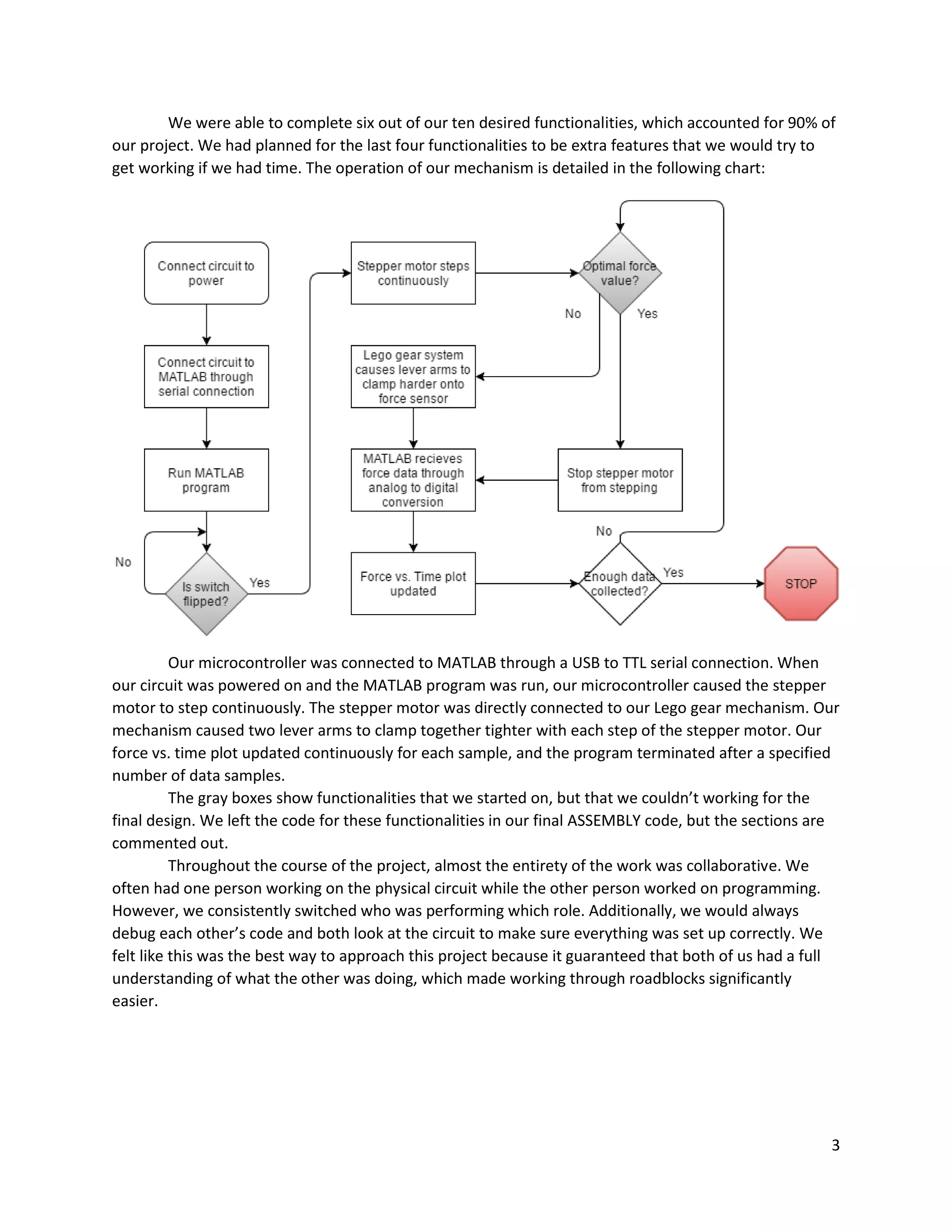
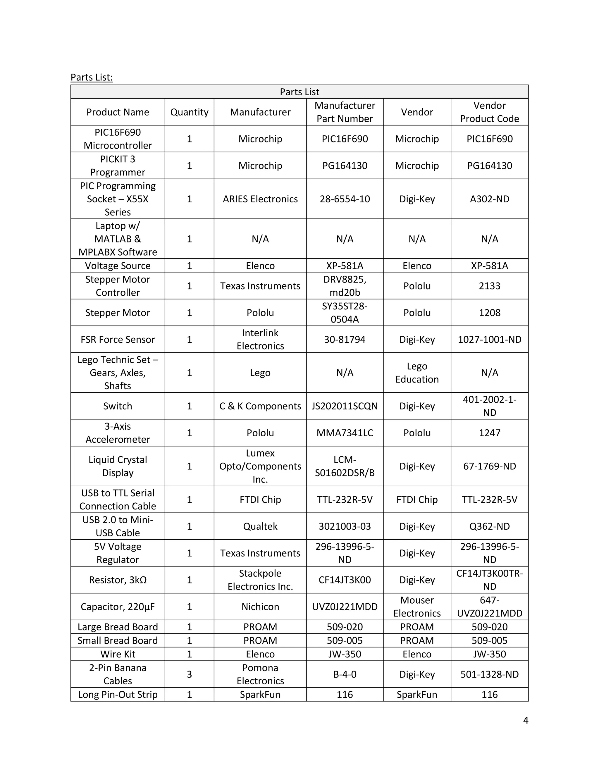
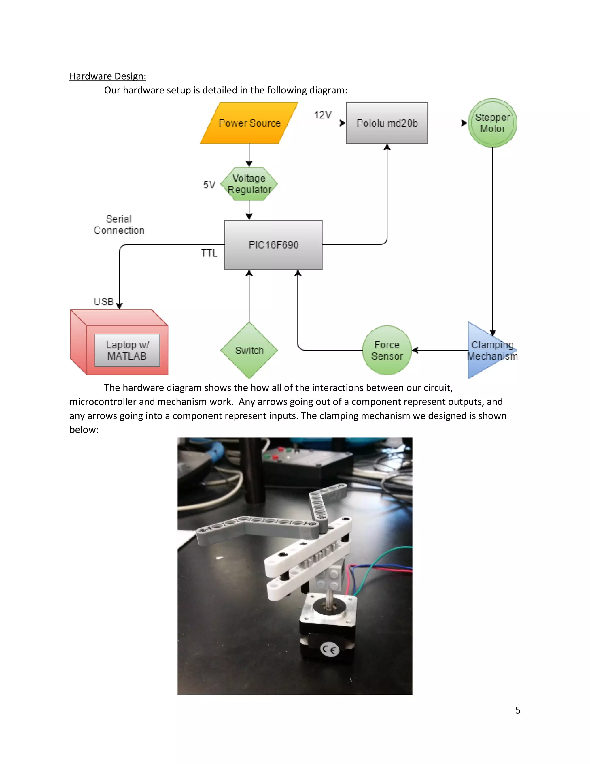
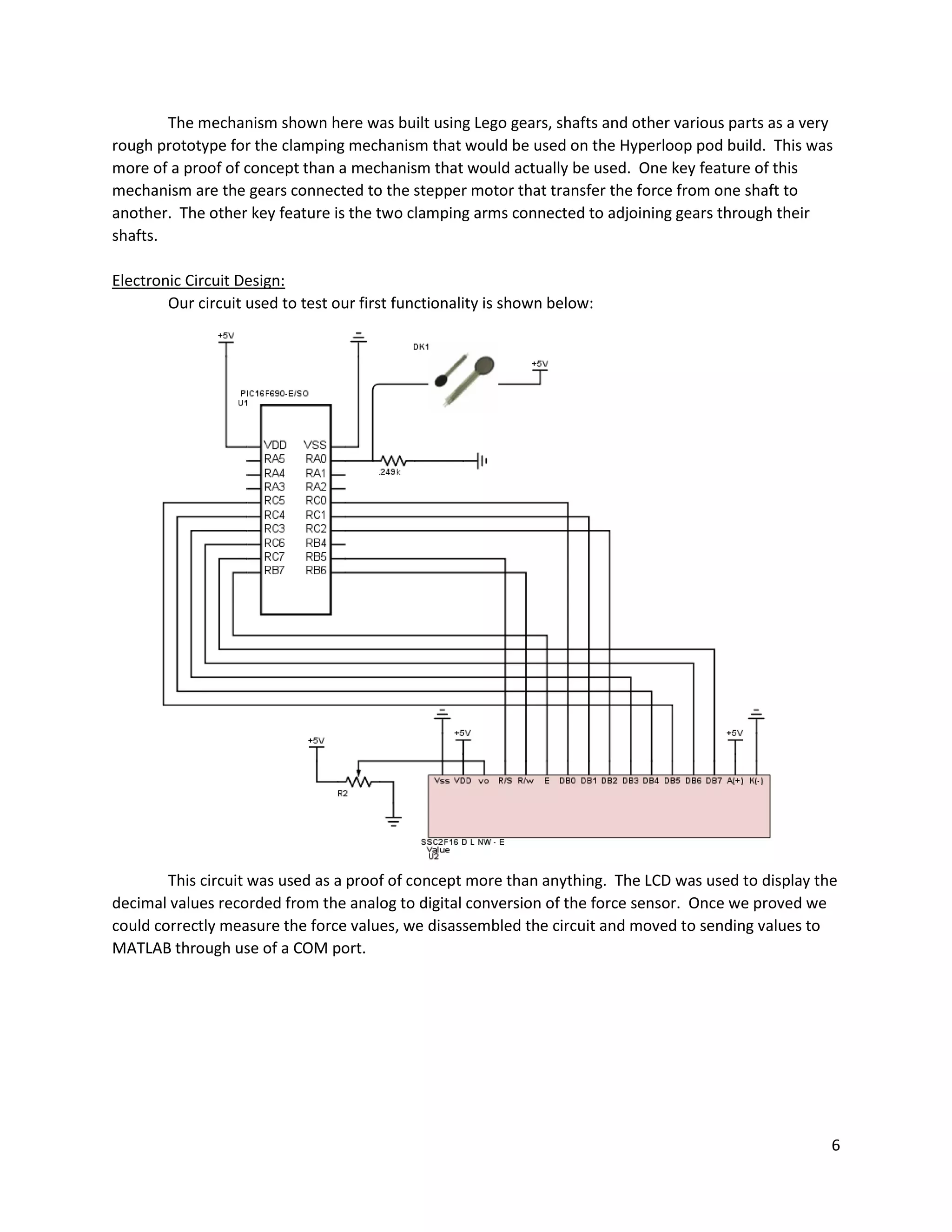
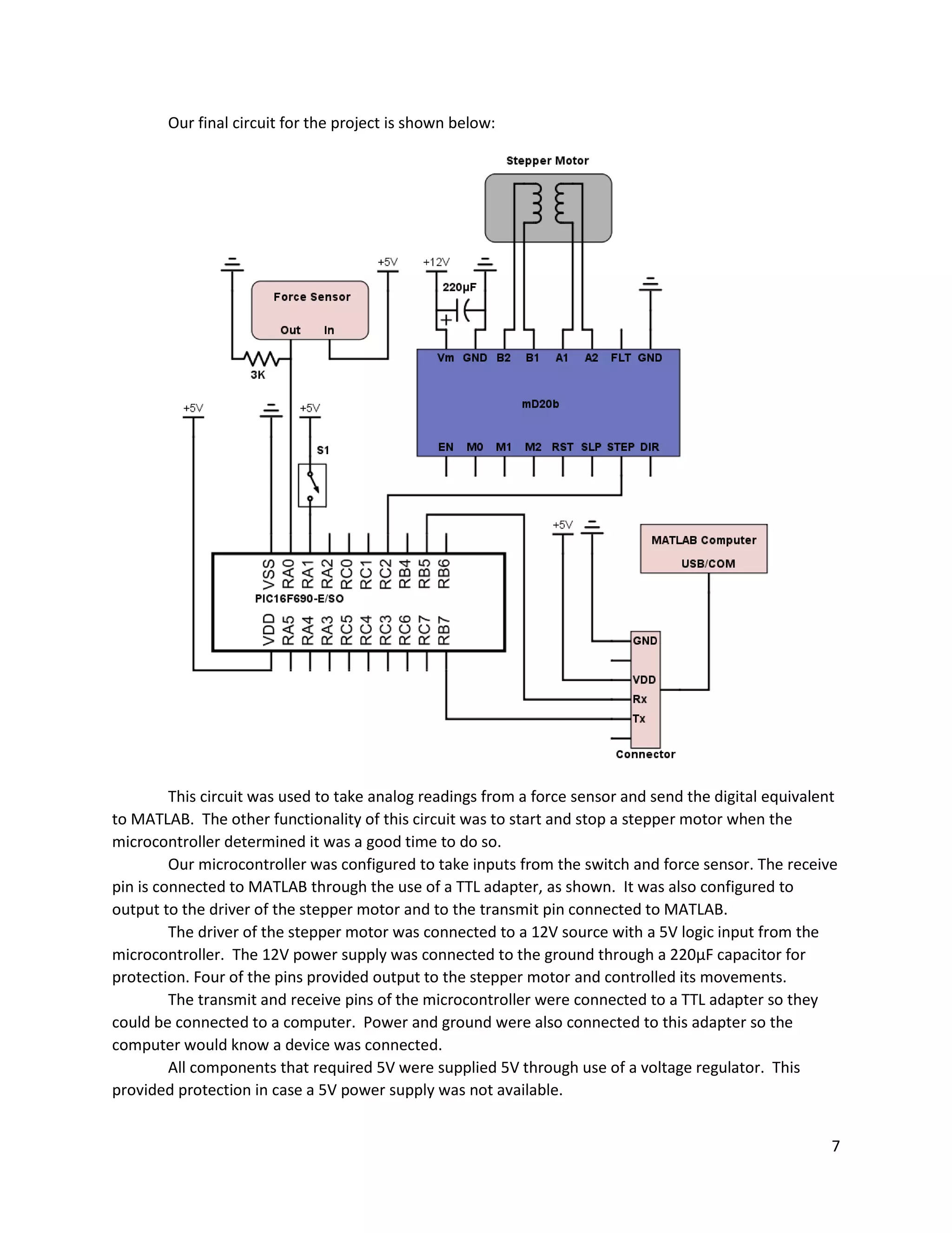
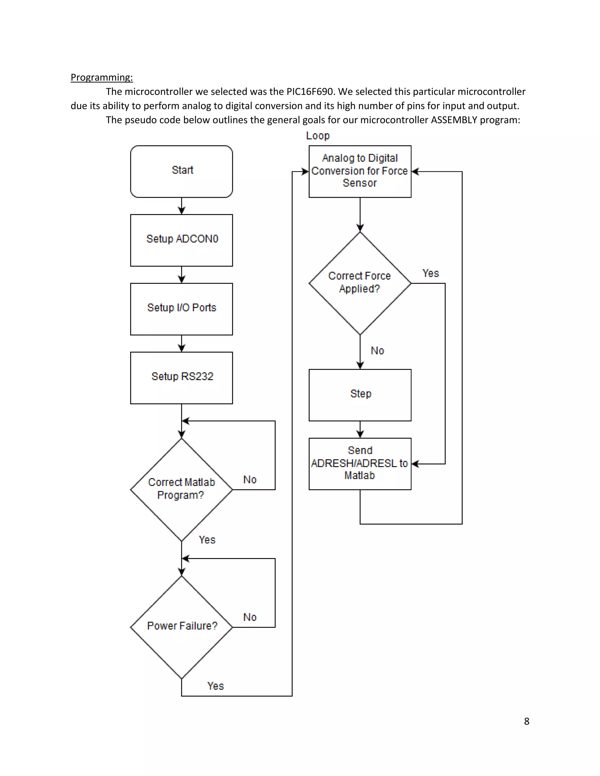
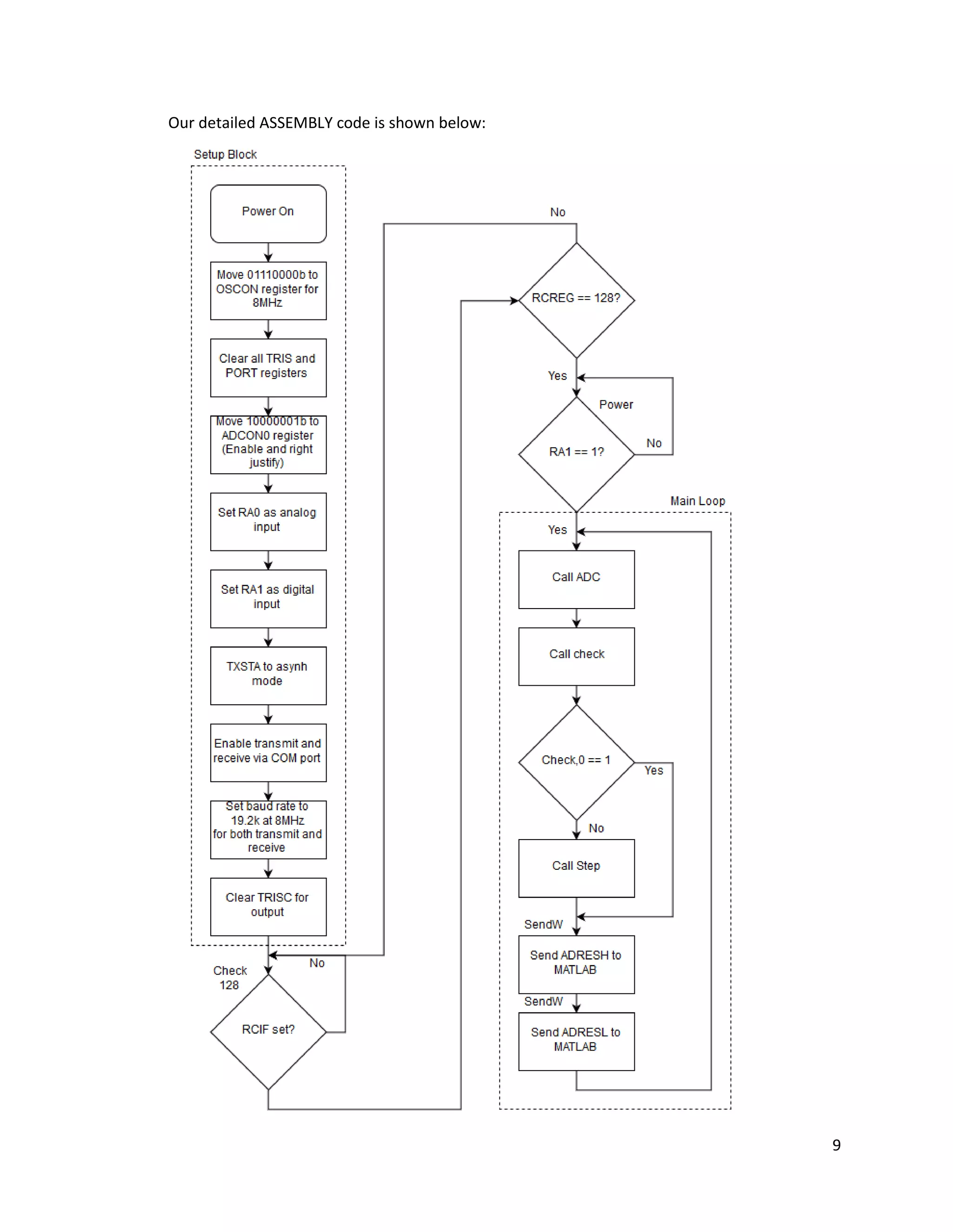
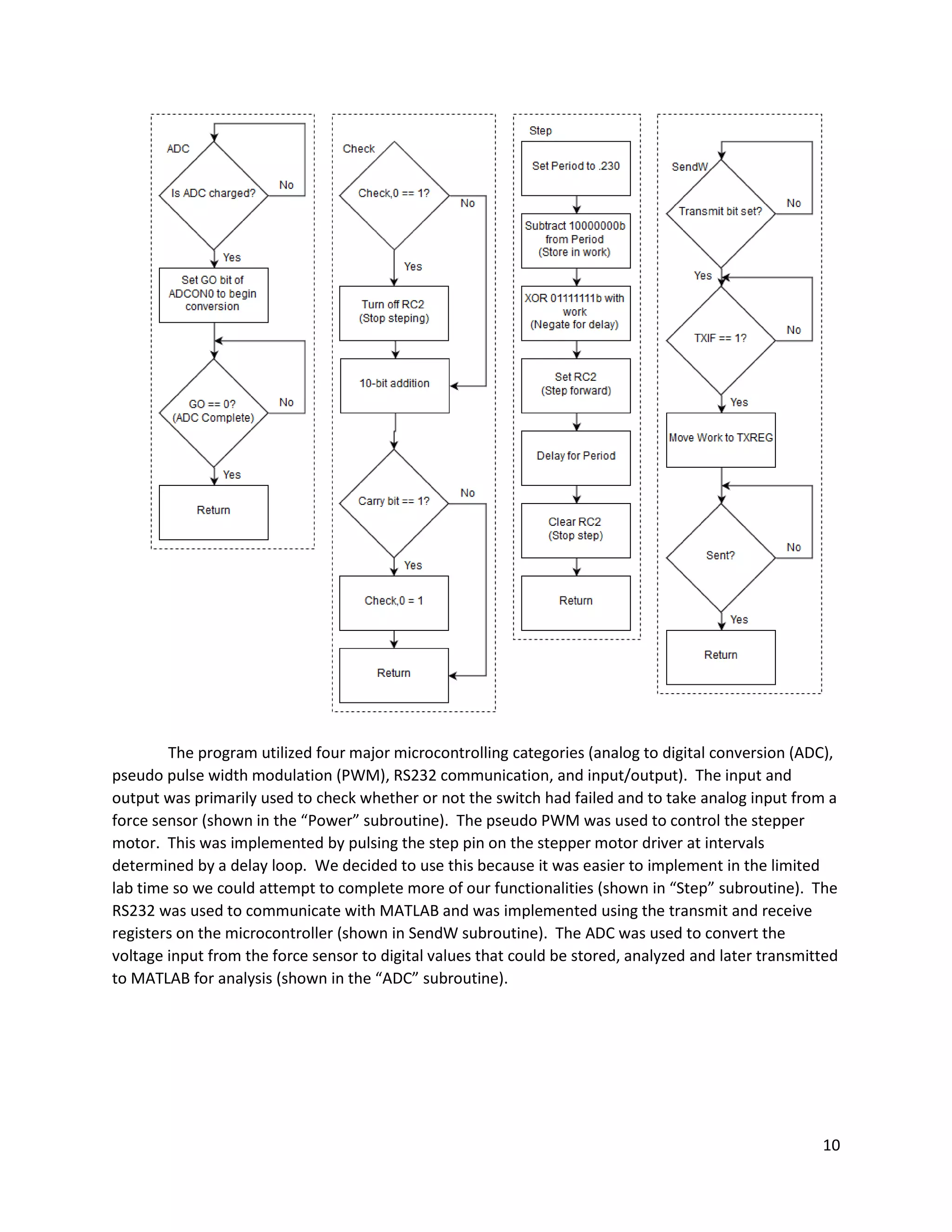
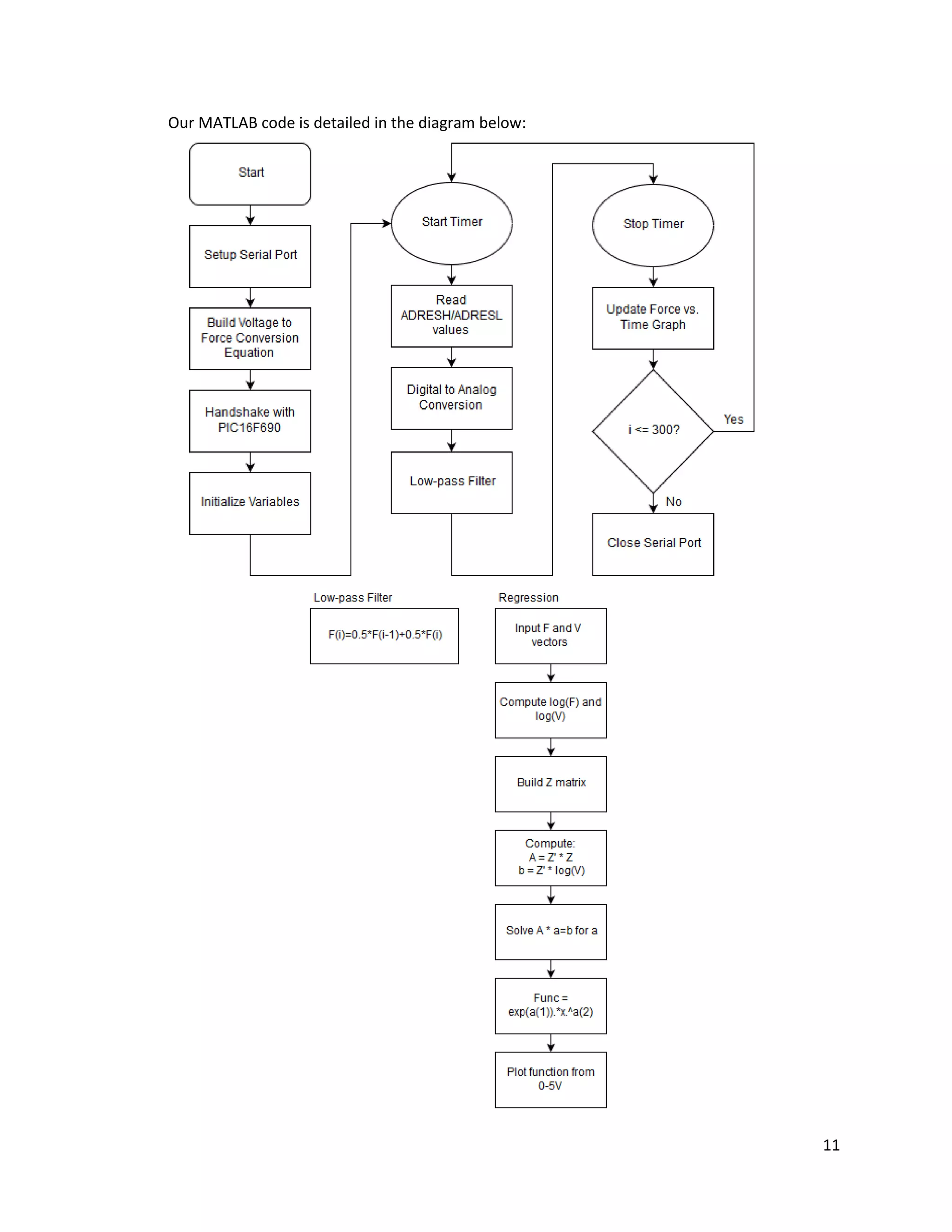
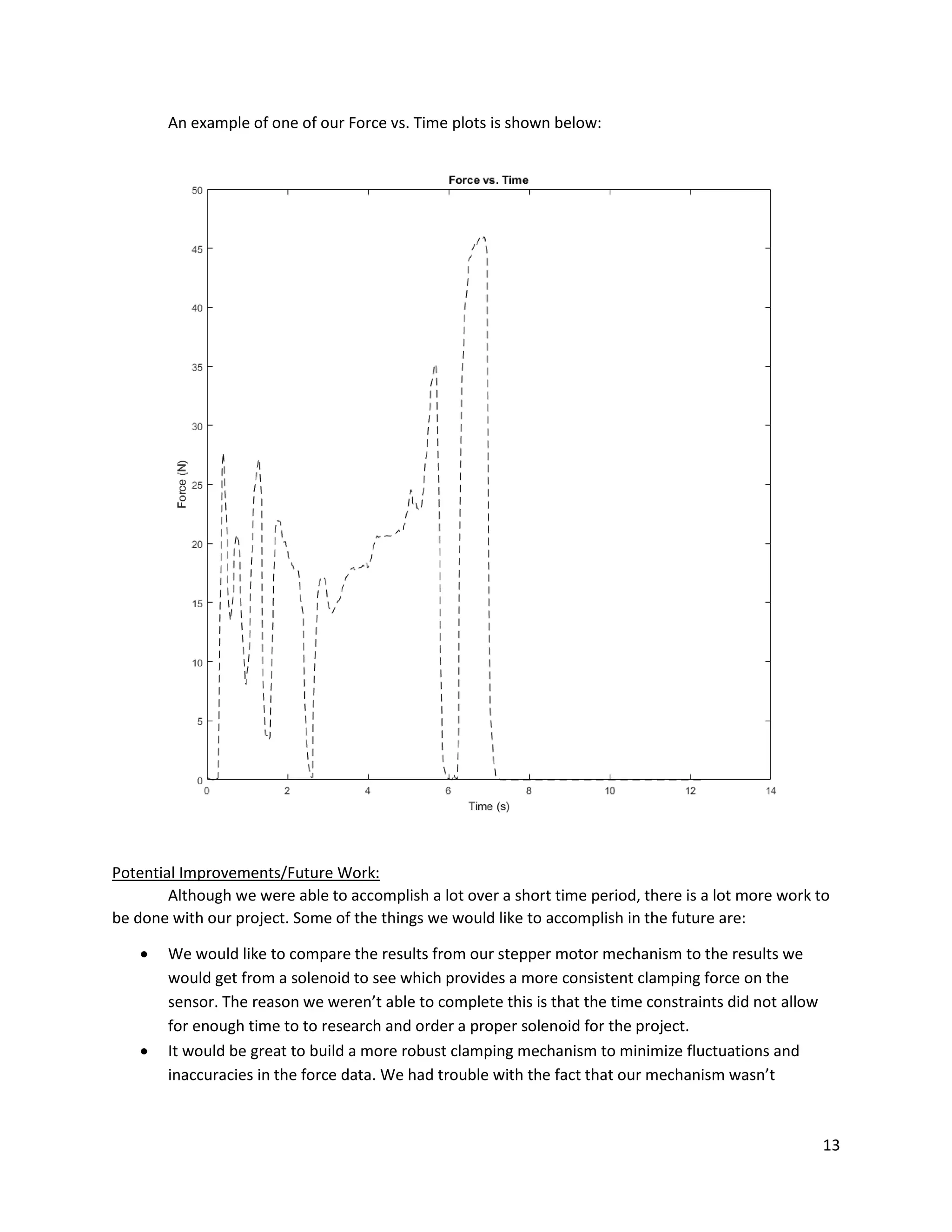
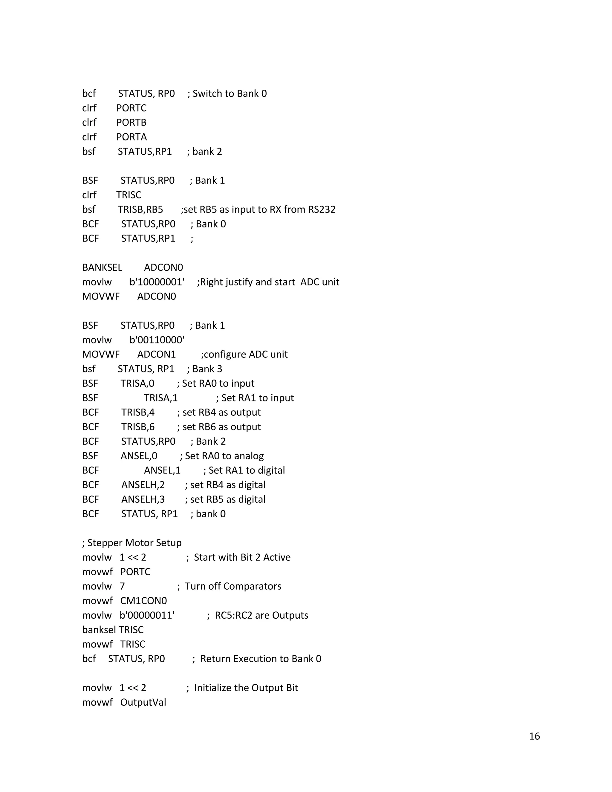
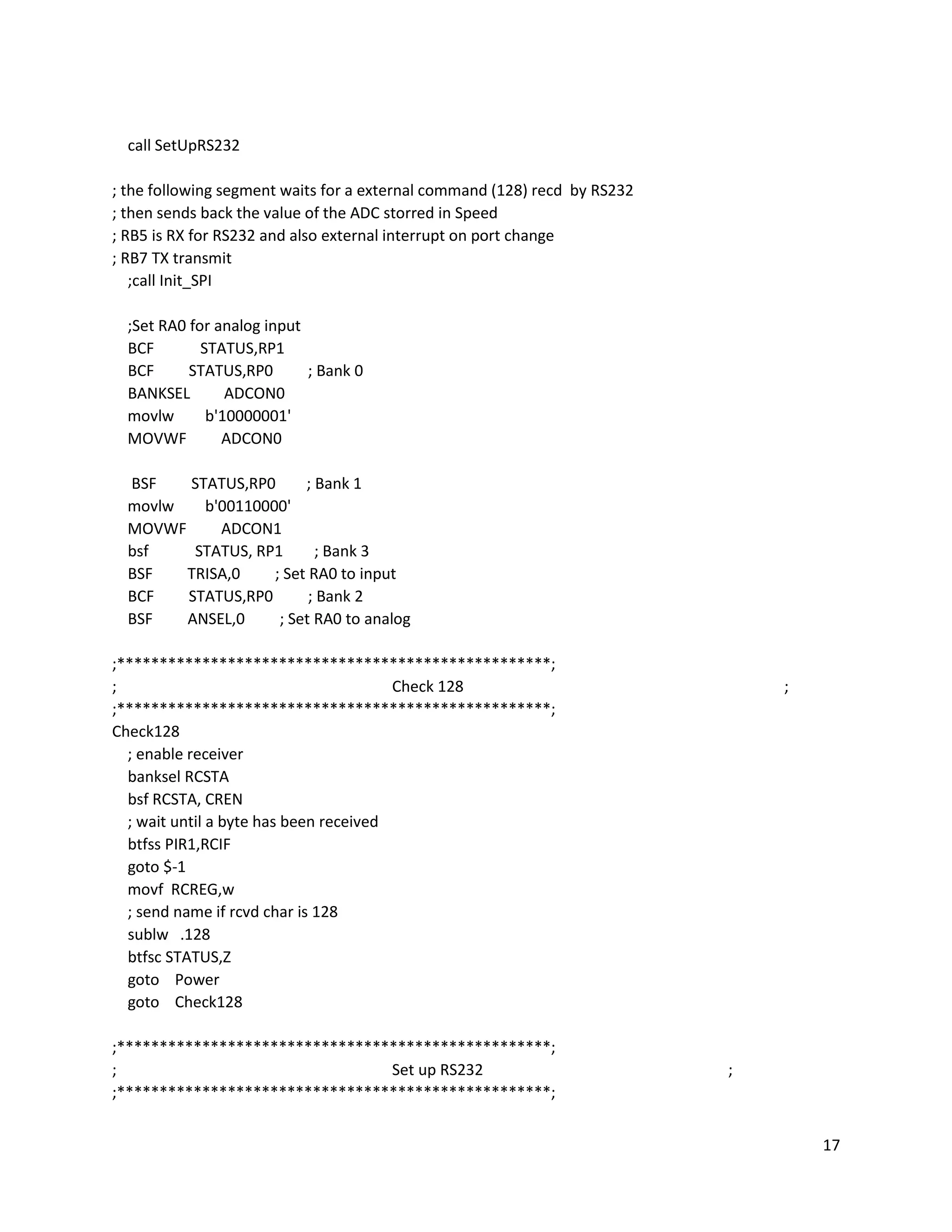
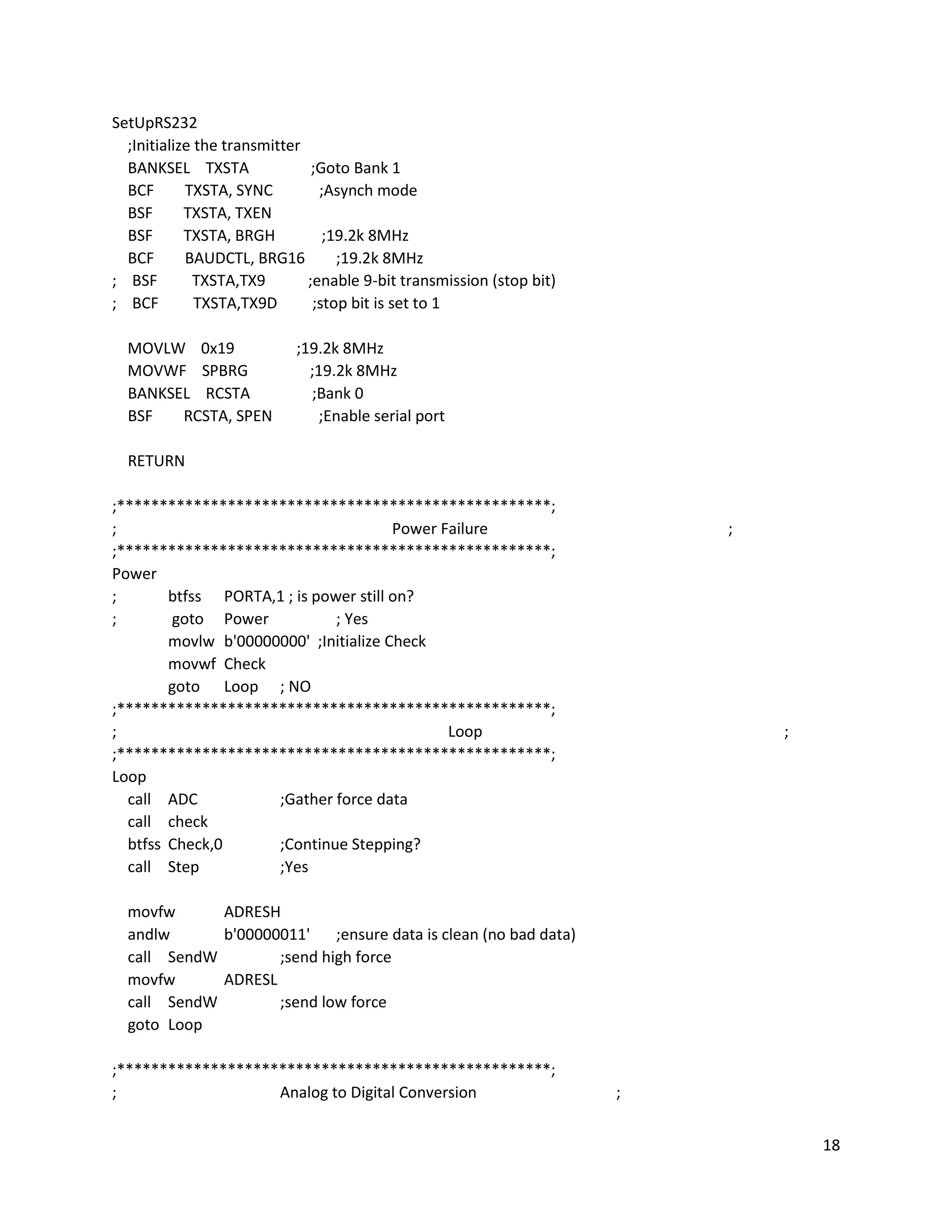
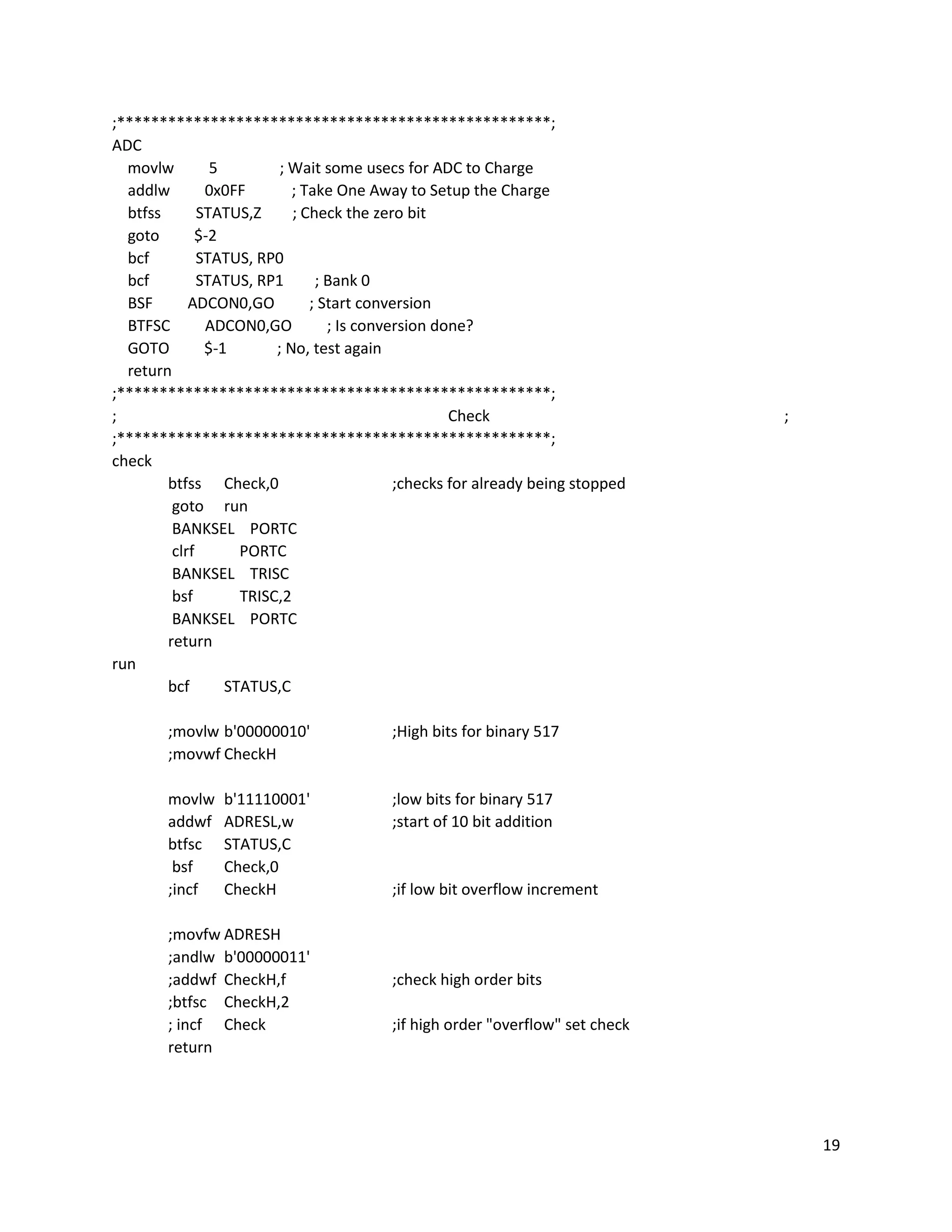
1
Names: Tristan Roberts and Jacob Grendahl
Project Title: Hyperloop Pod Emergency Brake
Team Number: Team 2
Project Dates: April 1, 2016 to May 6, 2016
Problem Description:
A Hyperloop pod design is meant to be a marketable product, so safety is of paramount
importance. We are members of the SpaceX Hyperloop Competition Club, and we’ve explored different
options to bring the pod to a controlled stop. Our primary braking method is implemented by reversing
the polarity of a linear accelerator, which is an entirely electrical system. However, our design needs to
be fail-safe and account for potential emergencies. Therefore, another braking system needs to be in
place to account for a loss of electrical power.
The application of our final project is a control system for the emergency braking system of our
team’s Hyperloop pod design. Our system is triggered when the primary braking system cuts out, and it
brings the pod to a controlled stop through friction by clamping a guide rail. We mimicked this situation
by using a stepper motor system to exert a controlled clamping force on a force sensor.
Project Objectives:
Our primary objective was to create a mechanism that exerted a controlled, measurable force
on a force sensor. We wanted to record the force data over time in MATLAB so we could visualize the
strength and consistency of the clamping force. Ideally, we also wanted to have an external interrupt
(e.g. a loss in electrical power, simulated by a switch) trigger the clamping motion. Eventually, we also
would have wanted the mechanism to clamp to an optimal force value based on the pod’s acceleration,
measured by an accelerometer.
Motivation for Topic:
Our motivation for this topic comes from us both being members of the SpaceX Hyperloop
Competition Team. For a design weekend at Texas A&M in January, our team designed multiple
subsystems of a Hyperloop pod, receiving great feedback from judges and peers. Our club is still
extremely interested in the concept, so we plan to design and build a full pod design for a potential
competition next year. This Mechatronics project is one small step towards that goal, because as a club
we know we want to utilize a friction-based emergency braking system. As a team, we intend to
continue work on the emergency brake concept outside of this class to produce a working model for use
on both test-scale and full-scale pods.
Desired Requirements:
 Our microcontroller will sense the response of a force sensor through analog-to-digital
conversion.
 The values we extract from the force sensor will be converted to a useful form (e.g. Newtons).
 A plot of force over time from the force sensor will be displayed in MATLAB.
 The plot in MATLAB will be continuously updated as time progresses.
 Any inaccuracies due to noise will be minimized through data filtering.
 The stepper motor system will cause a clamping force on the force sensor.
2
 By altering the input to the stepper motor, we will dynamically change the force applied to the
force sensor.
 We will stop the mechanism from clamping once it reaches a specified force value.
 The clamping force will be initiated using an external interrupt (a switch).
 A relationship will be established between acceleration and the ideal clamping force.
 The response of an accelerometer will cause the mechanism to exert the ideal clamping force.
Plan of Execution:
The goals we had, as described in the “Project Objectives” section, each required many smaller
developments. The steps of development for our project are detailed in the following table:
Project Functionalities
Implementation
Order
MCU
Functionality
Details of Project
Task
Project
Functionality
Percent of
Project
Complete?
1
Input/Output,
Analog/Digital,
LCD (for testing)
Measure the
response/value of
a force sensor
Display force
data over time
in MATLAB
15 X
2
USB to TTL Serial
Communication,
Input/Output
Transfer the force
values to MATLAB
15 X
3
Analog/Digital,
Mathematics
Convert the output
of the force sensor
to a useful unit
(e.g. Newtons)
10 X
4
Timers,
Mathematics
Plot the force data
over time
10 X
5
Pulse Width
Modulation,
Input/Output
Control a stepper
motor using PWM
Exert
controlled
clamping
(braking) force
to stop the pod
comfortably
20 X
6 Hardware
Create a system to
exert a clamping
force on the sensor
20 X
7
External
Interrupts,
Input/Output
Use a switch to
cause an external
interrupt in the
PIC16F690
Sense when
electrical
braking system
cuts out
3
8
External
Interrupts,
Input/Output
Trigger the
response of the
stepper motor
using a switch
2
9
Input/Output,
Analog/Digital
Measure the
response of an
accelerometer
Clamping force
responds to
the amount of
acceleration
3
10 Mathematics
Control the
clamping force
with the
accelerometer
2
3
We were able to complete six out of our ten desired functionalities, which accounted for 90% of
our project. We had planned for the last four functionalities to be extra features that we would try to
get working if we had time. The operation of our mechanism is detailed in the following chart:
Our microcontroller was connected to MATLAB through a USB to TTL serial connection. When
our circuit was powered on and the MATLAB program was run, our microcontroller caused the stepper
motor to step continuously. The stepper motor was directly connected to our Lego gear mechanism. Our
mechanism caused two lever arms to clamp together tighter with each step of the stepper motor. Our
force vs. time plot updated continuously for each sample, and the program terminated after a specified
number of data samples.
The gray boxes show functionalities that we started on, but that we couldn’t working for the
final design. We left the code for these functionalities in our final ASSEMBLY code, but the sections are
commented out.
Throughout the course of the project, almost the entirety of the work was collaborative. We
often had one person working on the physical circuit while the other person worked on programming.
However, we consistently switched who was performing which role. Additionally, we would always
debug each other’s code and both look at the circuit to make sure everything was set up correctly. We
felt like this was the best way to approach this project because it guaranteed that both of us had a full
understanding of what the other was doing, which made working through roadblocks significantly
easier.
4
Parts List:
Parts List
Product Name Quantity Manufacturer
Manufacturer
Part Number
Vendor
Vendor
Product Code
PIC16F690
Microcontroller
1 Microchip PIC16F690 Microchip PIC16F690
PICKIT 3
Programmer
1 Microchip PG164130 Microchip PG164130
PIC Programming
Socket – X55X
Series
1 ARIES Electronics 28-6554-10 Digi-Key A302-ND
Laptop w/
MATLAB &
MPLABX Software
1 N/A N/A N/A N/A
Voltage Source 1 Elenco XP-581A Elenco XP-581A
Stepper Motor
Controller
1 Texas Instruments
DRV8825,
md20b
Pololu 2133
Stepper Motor 1 Pololu
SY35ST28-
0504A
Pololu 1208
FSR Force Sensor 1
Interlink
Electronics
30-81794 Digi-Key 1027-1001-ND
Lego Technic Set –
Gears, Axles,
Shafts
1 Lego N/A
Lego
Education
N/A
Switch 1 C & K Components JS202011SCQN Digi-Key
401-2002-1-
ND
3-Axis
Accelerometer
1 Pololu MMA7341LC Pololu 1247
Liquid Crystal
Display
1
Lumex
Opto/Components
Inc.
LCM-
S01602DSR/B
Digi-Key 67-1769-ND
USB to TTL Serial
Connection Cable
1 FTDI Chip TTL-232R-5V FTDI Chip TTL-232R-5V
USB 2.0 to Mini-
USB Cable
1 Qualtek 3021003-03 Digi-Key Q362-ND
5V Voltage
Regulator
1 Texas Instruments
296-13996-5-
ND
Digi-Key
296-13996-5-
ND
Resistor, 3kΩ 1
Stackpole
Electronics Inc.
CF14JT3K00 Digi-Key
CF14JT3K00TR-
ND
Capacitor, 220μF 1 Nichicon UVZ0J221MDD
Mouser
Electronics
647-
UVZ0J221MDD
Large Bread Board 1 PROAM 509-020 PROAM 509-020
Small Bread Board 1 PROAM 509-005 PROAM 509-005
Wire Kit 1 Elenco JW-350 Elenco JW-350
2-Pin Banana
Cables
3
Pomona
Electronics
B-4-0 Digi-Key 501-1328-ND
Long Pin-Out Strip 1 SparkFun 116 SparkFun 116
5
Hardware Design:
Our hardware setup is detailed in the following diagram:
The hardware diagram shows the how all of the interactions between our circuit,
microcontroller and mechanism work. Any arrows going out of a component represent outputs, and
any arrows going into a component represent inputs. The clamping mechanism we designed is shown
below:
6
The mechanism shown here was built using Lego gears, shafts and other various parts as a very
rough prototype for the clamping mechanism that would be used on the Hyperloop pod build. This was
more of a proof of concept than a mechanism that would actually be used. One key feature of this
mechanism are the gears connected to the stepper motor that transfer the force from one shaft to
another. The other key feature is the two clamping arms connected to adjoining gears through their
shafts.
Electronic Circuit Design:
Our circuit used to test our first functionality is shown below:
This circuit was used as a proof of concept more than anything. The LCD was used to display the
decimal values recorded from the analog to digital conversion of the force sensor. Once we proved we
could correctly measure the force values, we disassembled the circuit and moved to sending values to
MATLAB through use of a COM port.
7
Our final circuit for the project is shown below:
This circuit was used to take analog readings from a force sensor and send the digital equivalent
to MATLAB. The other functionality of this circuit was to start and stop a stepper motor when the
microcontroller determined it was a good time to do so.
Our microcontroller was configured to take inputs from the switch and force sensor. The receive
pin is connected to MATLAB through the use of a TTL adapter, as shown. It was also configured to
output to the driver of the stepper motor and to the transmit pin connected to MATLAB.
The driver of the stepper motor was connected to a 12V source with a 5V logic input from the
microcontroller. The 12V power supply was connected to the ground through a 220μF capacitor for
protection. Four of the pins provided output to the stepper motor and controlled its movements.
The transmit and receive pins of the microcontroller were connected to a TTL adapter so they
could be connected to a computer. Power and ground were also connected to this adapter so the
computer would know a device was connected.
All components that required 5V were supplied 5V through use of a voltage regulator. This
provided protection in case a 5V power supply was not available.
8
Programming:
The microcontroller we selected was the PIC16F690. We selected this particular microcontroller
due its ability to perform analog to digital conversion and its high number of pins for input and output.
The pseudo code below outlines the general goals for our microcontroller ASSEMBLY program:
9
Our detailed ASSEMBLY code is shown below:
10
The program utilized four major microcontrolling categories (analog to digital conversion (ADC),
pseudo pulse width modulation (PWM), RS232 communication, and input/output). The input and
output was primarily used to check whether or not the switch had failed and to take analog input from a
force sensor (shown in the “Power” subroutine). The pseudo PWM was used to control the stepper
motor. This was implemented by pulsing the step pin on the stepper motor driver at intervals
determined by a delay loop. We decided to use this because it was easier to implement in the limited
lab time so we could attempt to complete more of our functionalities (shown in “Step” subroutine). The
RS232 was used to communicate with MATLAB and was implemented using the transmit and receive
registers on the microcontroller (shown in SendW subroutine). The ADC was used to convert the
voltage input from the force sensor to digital values that could be stored, analyzed and later transmitted
to MATLAB for analysis (shown in the “ADC” subroutine).
11
Our MATLAB code is detailed in the diagram below:
12
The MATLAB portion of the code follows the pattern of the diagram shown above. It takes
inputs coming from the microcontroller and converts the digital values to voltages, and then to force
values. The conversion from voltage to force was done by creating an equation through the use of
regression. Known points were read from the Voltage vs. Force diagram (shown below) in the force
sensor datasheet. These points were converted into log-log form for the curve fitting. When the fitting
was complete, the equation was converted back to the non-linear form to be used by the main loop.
The plot we used to perform our regression analysis is shown below:
In the voltage divider circuit, a 3kΩ resistor was used for RM; this is because we desired the
shallowest curve for more accuracy when using smaller force values.
Testing/Proof of Operation/Conclusion:
In reality, certain components of our project work very well, but we could not get them all to
work in unison. For example, our live plot in MATLAB works extremely well as someone squeezes the
force sensor with their fingers. The low-pass filter allows the force diagram to be almost entirely smooth
with no noticeable noise. Also, as we run the MATLAB program, the stepper motor steps at a good rate
and the lever arms clamp together. However, we could not get our clamping mechanism to produce a
high enough force to be recognized by the sensor. This is because the mechanism wasn’t very robust;
one of us had to fix the position of the mechanism and stepper motor to keep them from rotating with
the lever arms. Another thing that contributed to this was that the surface between the two lever arms
did not provide a good enough clamping surface to be recognized by the force sensor.
The only other remaining bugs from our main goals are the switch not working and the motor
not stopping when the selected force value is applied. In the current state of the project, when the
circuit is plugged into a 5V and 12V supply, there should be no moving components, but the stepper
motor should hum. When the MATLAB program is run, the stepper motor should start rotating at a
consistent speed, and a plot should appear on the screen of the computer. If the force sensor is
squeezed, the live updating plot should show an accurate representation of how the sensor was
squeezed.
13
An example of one of our Force vs. Time plots is shown below:
Potential Improvements/Future Work:
Although we were able to accomplish a lot over a short time period, there is a lot more work to
be done with our project. Some of the things we would like to accomplish in the future are:
 We would like to compare the results from our stepper motor mechanism to the results we
would get from a solenoid to see which provides a more consistent clamping force on the
sensor. The reason we weren’t able to complete this is that the time constraints did not allow
for enough time to to research and order a proper solenoid for the project.
 It would be great to build a more robust clamping mechanism to minimize fluctuations and
inaccuracies in the force data. We had trouble with the fact that our mechanism wasn’t
14
squeezing the force sensor as tightly as we wanted, so we think a better design could remedy
some of our major issues.
 We need to simulate an electrical failure using a switch. We were close to getting this
functionality working before the project deadline, so we would just need to debug our code
further to achieve this.
 Eventually, our ultimate goal is to clamp to an optimal force value based on the pod’s
acceleration, which we want to mimic with an accelerometer. This would allow our pod design
to reach a controlled and comfortable stop.
 We would like to research clamping materials to get an optimal coefficient of friction for use on
a Hyperloop pod.
 After all our functionalities are complete, we would like to test our idea using a small-scale
version of our Hyperloop pod design.
Troubleshooting:
One difficulty that we had with the project was trying to get the stepper motor to stop stepping
after reaching a certain force value. It seemed like we had the logic correct, but a minor error in the
code or wiring may have caused it to malfunction. Another issue we had was using the switch to trigger
the response of the stepper motor. For some reason, we couldn’t get the port to recognize when the
switch was flipped.
When troubleshooting earlier parts of the project, commenting out specific sections or lines of
code were useful for evaluating which parts of the code were actually working. Also, when applicable, it
really helped us to use the debugging tool in MPLABX.
What We Have Learned:
This project was our first exposure to controls and the first place that we could apply our
knowledge of circuits in a practical way. What we would like to take away from this project and apply to
our careers is the ability to take a very complex project, and break it into many simple functionalities. By
utilizing the information taught to us during lecture and looking through data sheets for our requested
components, we were able to work our way through numerous challenges presented by our choice of
project. Theoretical topics such as 8-bit and 10-bit mathematics were vital for our functionalities, so
learning that material during lecture really aided us in practice.
15
Appendices:
ASSEMBLY Code – Team2_Final_Project.asm:
;Authors: Jacob Grendahl, Tristan Roberts
;Date: May 6, 2016
;Class: AME 487
;Assignment: Final Project
;File: Team2_Final_Project.asm
;
;Description:
; This is meant to program a PIC16F690
; The controller is supposed to control an emergency braking system
; through use of analog input from a force sensor, and output to a stepper motor.
; When matlab begins to listen and power failure has been simulated, the stepper
; motor should begin to step.
;
; When the optimal force value is reached, the stepper motor should stop stepping.
; The controller should be sending the digital force values to matlab indefinitely.
List P=16f690
#include <p16f690.inc>
;Codeprotect on, watchdog off, internal high speed osc, powerup timer on, clear reset off, brown out
off
__CONFIG _CP_ON & _WDT_OFF & _INTOSCIO & _PWRTE_ON & _MCLRE_OFF & _BOR_OFF
CBLOCK 0x20
temp
num
Dlay
Period
OutputVal
Check
CheckH
ENDC
org 0x00
goto start
;***************************************************;
;Initialize Oscillator, 8MHz internal
;***************************************************;
start
; ADC & MATLAB Setup
bsf STATUS, RP0 ; switch to Bank 1
MOVLW b'01110000' ; Set internal oscillator frequency to 8 MHz
MOVWF OSCCON
16
bcf STATUS, RP0 ; Switch to Bank 0
clrf PORTC
clrf PORTB
clrf PORTA
bsf STATUS,RP1 ; bank 2
BSF STATUS,RP0 ; Bank 1
clrf TRISC
bsf TRISB,RB5 ;set RB5 as input to RX from RS232
BCF STATUS,RP0 ; Bank 0
BCF STATUS,RP1 ;
BANKSEL ADCON0
movlw b'10000001' ;Right justify and start ADC unit
MOVWF ADCON0
BSF STATUS,RP0 ; Bank 1
movlw b'00110000'
MOVWF ADCON1 ;configure ADC unit
bsf STATUS, RP1 ; Bank 3
BSF TRISA,0 ; Set RA0 to input
BSF TRISA,1 ; Set RA1 to input
BCF TRISB,4 ; set RB4 as output
BCF TRISB,6 ; set RB6 as output
BCF STATUS,RP0 ; Bank 2
BSF ANSEL,0 ; Set RA0 to analog
BCF ANSEL,1 ; Set RA1 to digital
BCF ANSELH,2 ; set RB4 as digital
BCF ANSELH,3 ; set RB5 as digital
BCF STATUS, RP1 ; bank 0
; Stepper Motor Setup
movlw 1 << 2 ; Start with Bit 2 Active
movwf PORTC
movlw 7 ; Turn off Comparators
movwf CM1CON0
movlw b'00000011' ; RC5:RC2 are Outputs
banksel TRISC
movwf TRISC
bcf STATUS, RP0 ; Return Execution to Bank 0
movlw 1 << 2 ; Initialize the Output Bit
movwf OutputVal
17
call SetUpRS232
; the following segment waits for a external command (128) recd by RS232
; then sends back the value of the ADC storred in Speed
; RB5 is RX for RS232 and also external interrupt on port change
; RB7 TX transmit
;call Init_SPI
;Set RA0 for analog input
BCF STATUS,RP1
BCF STATUS,RP0 ; Bank 0
BANKSEL ADCON0
movlw b'10000001'
MOVWF ADCON0
BSF STATUS,RP0 ; Bank 1
movlw b'00110000'
MOVWF ADCON1
bsf STATUS, RP1 ; Bank 3
BSF TRISA,0 ; Set RA0 to input
BCF STATUS,RP0 ; Bank 2
BSF ANSEL,0 ; Set RA0 to analog
;***************************************************;
; Check 128 ;
;***************************************************;
Check128
; enable receiver
banksel RCSTA
bsf RCSTA, CREN
; wait until a byte has been received
btfss PIR1,RCIF
goto $-1
movf RCREG,w
; send name if rcvd char is 128
sublw .128
btfsc STATUS,Z
goto Power
goto Check128
;***************************************************;
; Set up RS232 ;
;***************************************************;
18
SetUpRS232
;Initialize the transmitter
BANKSEL TXSTA ;Goto Bank 1
BCF TXSTA, SYNC ;Asynch mode
BSF TXSTA, TXEN
BSF TXSTA, BRGH ;19.2k 8MHz
BCF BAUDCTL, BRG16 ;19.2k 8MHz
; BSF TXSTA,TX9 ;enable 9-bit transmission (stop bit)
; BCF TXSTA,TX9D ;stop bit is set to 1
MOVLW 0x19 ;19.2k 8MHz
MOVWF SPBRG ;19.2k 8MHz
BANKSEL RCSTA ;Bank 0
BSF RCSTA, SPEN ;Enable serial port
RETURN
;***************************************************;
; Power Failure ;
;***************************************************;
Power
; btfss PORTA,1 ; is power still on?
; goto Power ; Yes
movlw b'00000000' ;Initialize Check
movwf Check
goto Loop ; NO
;***************************************************;
; Loop ;
;***************************************************;
Loop
call ADC ;Gather force data
call check
btfss Check,0 ;Continue Stepping?
call Step ;Yes
movfw ADRESH
andlw b'00000011' ;ensure data is clean (no bad data)
call SendW ;send high force
movfw ADRESL
call SendW ;send low force
goto Loop
;***************************************************;
; Analog to Digital Conversion ;
19
;***************************************************;
ADC
movlw 5 ; Wait some usecs for ADC to Charge
addlw 0x0FF ; Take One Away to Setup the Charge
btfss STATUS,Z ; Check the zero bit
goto $-2
bcf STATUS, RP0
bcf STATUS, RP1 ; Bank 0
BSF ADCON0,GO ; Start conversion
BTFSC ADCON0,GO ; Is conversion done?
GOTO $-1 ; No, test again
return
;***************************************************;
; Check ;
;***************************************************;
check
btfss Check,0 ;checks for already being stopped
goto run
BANKSEL PORTC
clrf PORTC
BANKSEL TRISC
bsf TRISC,2
BANKSEL PORTC
return
run
bcf STATUS,C
;movlw b'00000010' ;High bits for binary 517
;movwf CheckH
movlw b'11110001' ;low bits for binary 517
addwf ADRESL,w ;start of 10 bit addition
btfsc STATUS,C
bsf Check,0
;incf CheckH ;if low bit overflow increment
;movfw ADRESH
;andlw b'00000011'
;addwf CheckH,f ;check high order bits
;btfsc CheckH,2
; incf Check ;if high order "overflow" set check
return
20
;***************************************************;
; Step ;
;***************************************************;
Step
BANKSEL PORTC
movlw d'230'
movwf Period
movlw 0x80 ; Forwards or Reverse?
subwf Period, w
Forwards: ; Move Stepper Forwards
xorlw 0x7F ; Negate the Value for Delay
movwf Period
rlf OutputVal, w ; Shift the Saved Value
andlw b'00111100'
btfsc PORTC, 5 ; Roll Over?
iorlw 1 << 2
movwf PORTC
movwf OutputVal ; Save New Set Bit
DlayLoop: ; Repeat Delay Loop for "Period"
movlw HIGH ((1000 / 5) + 256)
movwf Dlay
movlw d'25'
addlw -1
btfsc STATUS, Z
decfsz Dlay, f
goto $ - 3
decfsz Period, f
goto DlayLoop
return
;***************************************************;
; Send Work Register ;
;***************************************************;
SendW
;check status of transmit bit, wait until set
BANKSEL TXSTA
BTFSS TXSTA, TRMT
GOTO $-1
BANKSEL PIR1
BTFSS PIR1, TXIF
GOTO $-1
21
BANKSEL TXSTA
BSF TXSTA,TX9D ;stop bit is set to 1
;Load working register into TXREG
BANKSEL TXREG
MOVWF TXREG
;Wait until character is sent
BANKSEL TXSTA
BTFSS TXSTA, TRMT
GOTO $-1
skipsend
RETURN
END
22
MATLAB Code – ForceConversion.m:
%Names: Jacob Grendahl, Tristan Roberts
%Date: May 6, 2016
%Class: AME 487
%Assignment: Final Project
%File: ForceConversion.m
%
%Description:
% This file is responsible for converting the binary bits recieved
% into force values. This is achieved by first creating an equation
% that converts voltage to force, then running through the main loop.
% The main loop constantly times the conversions and updates a force vs
% time plot.
out=instrfind();
delete(out);
clc;clear;
run('Regression');
s = serial('COM6'); %Serial port configuration
set(s,'BaudRate',19200);
set(s,'InputBufferSize',2);
%--------------------------------------------------------------------------
fopen(s) %Open serial port
N = 500;
fwrite(s,128,'async') %Send interupt signal to the microcontroller
ii=2;
t(1)=0;
while ii<=N
tic
out(ii,1) = fread(s,1,'uint8'); %Read data from the input buffer
switch out(ii,1)
case 3
out(ii,1)=2^9+2^8;
case 2
out(ii,1)=2^9;
case 1
out(ii,1)=2^8;
case 0
out(ii,1)=0;
otherwise
out=out(1:ii-1,:);
continue
end
out(ii,2) = fread(s,1,'uint8'); %Read data from the input buffer
b=toc;
t(ii)=t(ii-1)+b;
Vout(ii)=(out(ii,1)+out(ii,2))/1024*5; %DAC for voltage readout
F(ii)=Func(Vout(ii));
F(ii)=lowpassfilter(F(ii-1),F(ii));
plot(t(1:ii),F(1:ii),'--k');
23
drawnow
xlabel('Time (s)');
ylabel('Force (N)');
title('Force vs. Time');
ii=ii+1;
end
%--------------------------------------------------------------------------
fclose(s) %Close serial port
delete(s)
clear s
24
MATLAB Code – lowpassfilter.m:
%Names: Jacob Grendahl, Tristan Roberts
%Date: May 6, 2016
%Class: AME 487
%Assignment: Final Project
%File: lowpassfilter.m
%
%Description:
% This file removes noise from the force values that are taken
function F=lowpassfilter(F0,F1)
F=0.5*F0+0.5*F1;
end
25
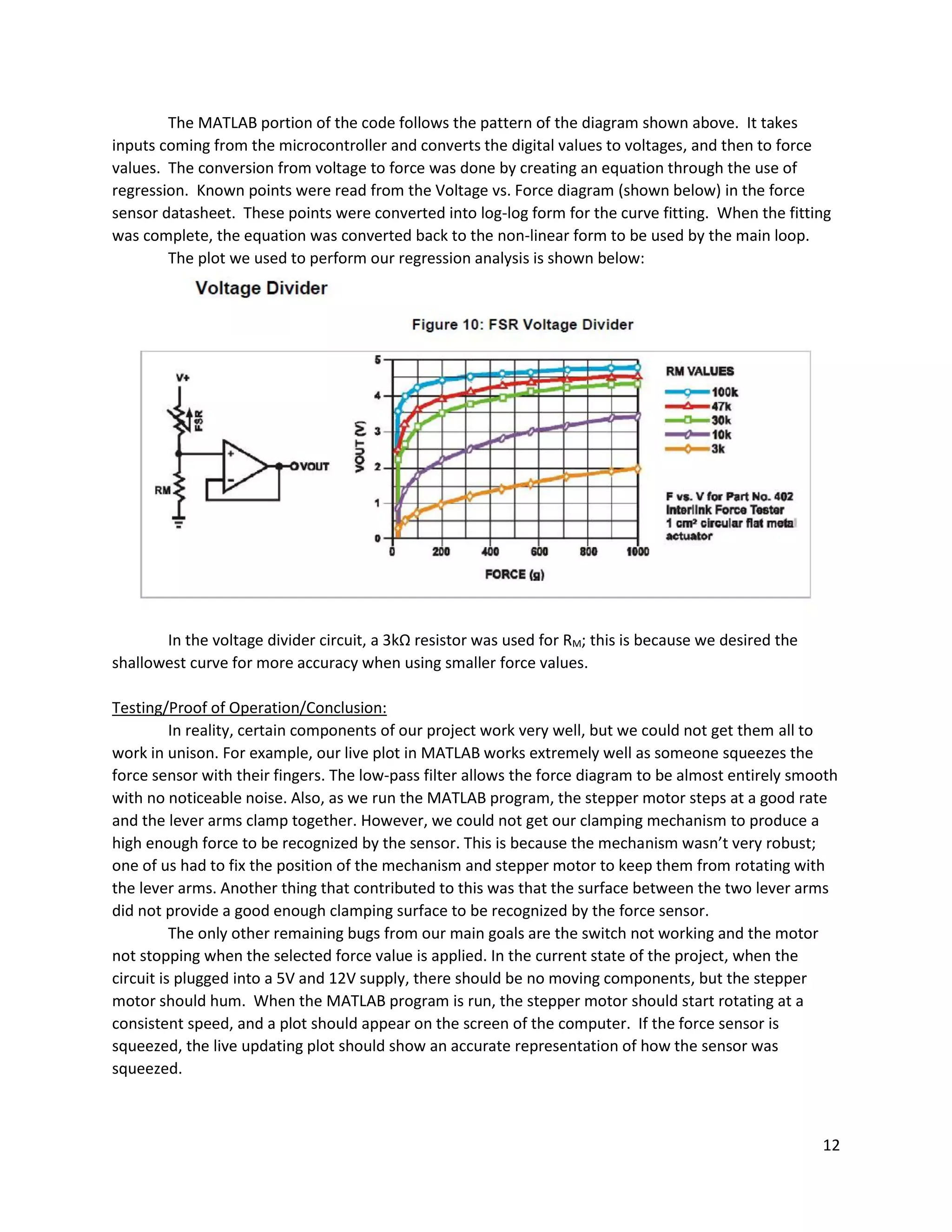
MATLAB Code – Regression.m:
%Names: Jacob Grendahl, Tristan Roberts
%Date: May 6, 2016
%Class: AME 487
%Assignment: Final Project
%File: Regression.m
%
%Description:
% This file is resopisible for building the equation that converts
% voltage to force values.
F=9.8/1000*[20 50 95 195 310 440 570 705 900 1000];
V=[0.35 0.5 0.7 1 1.2 1.45 1.625 1.8 1.95 2];
X=log(V);
Y=log(F);
Z=[ones(length(V),1) X'];
A=Z'*Z;
b=Z'*Y';
a=Ab;
x=0:0.1:5;
y=exp(a(1)).*x.^a(2);
Func=@(x)exp(a(1)).*x.^a(2);
plot(V,F,'or',x,y,'-k');
xlabel('Voltage Out (V)');
ylabel('Force (N)');
title('Force vs. Voltage Output');
26
The necessary data sheets required to complete this project are attached in a separate folder
labeled “Appendices.” The included data sheets are as follows:
 PIC16F690, Microchip
 FSR Force Sensor, Interlink Electronics
 SY35ST28-0504A Stepper Motor, Pololu
 DRV8825 Stepper Motor Controller, Texas Instruments
A lot of the information we used about the stepper motor and stepper motor controller came
from the following links:
 Stepper Motor: https://www.pololu.com/product/1208/resources
 Stepper Motor Controller: https://www.pololu.com/product/2133
27
Works Cited
DRV8825 Stepper Motor Driver Carrier, High Current. Tech. Pololu, n.d. Web. 28 Apr. 2016.
FSR Integration Guide. Tech. Interlink Electronics, n.d. PDF. 28 Apr. 2016.
Hyperloop Alpha. Tech. SpaceX, 12 Aug. 2013. PDF. 28 Apr. 2016.
Hyperloop Braking System Render. Digital image. Delft Hyperloop. Mkb Brandstof, 22 Jan. 2016. Web. 28
Apr. 2016.
PIC16F690 Data Sheet. Tech. Microchip, n.d. PDF. 28 Apr. 2016.
SY35ST28-0504A Stepper Motor Data Sheet. Tech. Pololu, n.d. PDF. 28 Apr. 2016.
The University of Arizona Air Bearings & Suspension Hyperloop Pod Subsystem Design. Tech. Tucson: The
University of Arizona Hyperloop Competition Team, 28 Jan. 2016. PPT. 28 Apr. 2016.

Team2_Final_Project_Documentation

  • 1.
    1 Names: Tristan Robertsand Jacob Grendahl Project Title: Hyperloop Pod Emergency Brake Team Number: Team 2 Project Dates: April 1, 2016 to May 6, 2016 Problem Description: A Hyperloop pod design is meant to be a marketable product, so safety is of paramount importance. We are members of the SpaceX Hyperloop Competition Club, and we’ve explored different options to bring the pod to a controlled stop. Our primary braking method is implemented by reversing the polarity of a linear accelerator, which is an entirely electrical system. However, our design needs to be fail-safe and account for potential emergencies. Therefore, another braking system needs to be in place to account for a loss of electrical power. The application of our final project is a control system for the emergency braking system of our team’s Hyperloop pod design. Our system is triggered when the primary braking system cuts out, and it brings the pod to a controlled stop through friction by clamping a guide rail. We mimicked this situation by using a stepper motor system to exert a controlled clamping force on a force sensor. Project Objectives: Our primary objective was to create a mechanism that exerted a controlled, measurable force on a force sensor. We wanted to record the force data over time in MATLAB so we could visualize the strength and consistency of the clamping force. Ideally, we also wanted to have an external interrupt (e.g. a loss in electrical power, simulated by a switch) trigger the clamping motion. Eventually, we also would have wanted the mechanism to clamp to an optimal force value based on the pod’s acceleration, measured by an accelerometer. Motivation for Topic: Our motivation for this topic comes from us both being members of the SpaceX Hyperloop Competition Team. For a design weekend at Texas A&M in January, our team designed multiple subsystems of a Hyperloop pod, receiving great feedback from judges and peers. Our club is still extremely interested in the concept, so we plan to design and build a full pod design for a potential competition next year. This Mechatronics project is one small step towards that goal, because as a club we know we want to utilize a friction-based emergency braking system. As a team, we intend to continue work on the emergency brake concept outside of this class to produce a working model for use on both test-scale and full-scale pods. Desired Requirements:  Our microcontroller will sense the response of a force sensor through analog-to-digital conversion.  The values we extract from the force sensor will be converted to a useful form (e.g. Newtons).  A plot of force over time from the force sensor will be displayed in MATLAB.  The plot in MATLAB will be continuously updated as time progresses.  Any inaccuracies due to noise will be minimized through data filtering.  The stepper motor system will cause a clamping force on the force sensor.
  • 2.
    2  By alteringthe input to the stepper motor, we will dynamically change the force applied to the force sensor.  We will stop the mechanism from clamping once it reaches a specified force value.  The clamping force will be initiated using an external interrupt (a switch).  A relationship will be established between acceleration and the ideal clamping force.  The response of an accelerometer will cause the mechanism to exert the ideal clamping force. Plan of Execution: The goals we had, as described in the “Project Objectives” section, each required many smaller developments. The steps of development for our project are detailed in the following table: Project Functionalities Implementation Order MCU Functionality Details of Project Task Project Functionality Percent of Project Complete? 1 Input/Output, Analog/Digital, LCD (for testing) Measure the response/value of a force sensor Display force data over time in MATLAB 15 X 2 USB to TTL Serial Communication, Input/Output Transfer the force values to MATLAB 15 X 3 Analog/Digital, Mathematics Convert the output of the force sensor to a useful unit (e.g. Newtons) 10 X 4 Timers, Mathematics Plot the force data over time 10 X 5 Pulse Width Modulation, Input/Output Control a stepper motor using PWM Exert controlled clamping (braking) force to stop the pod comfortably 20 X 6 Hardware Create a system to exert a clamping force on the sensor 20 X 7 External Interrupts, Input/Output Use a switch to cause an external interrupt in the PIC16F690 Sense when electrical braking system cuts out 3 8 External Interrupts, Input/Output Trigger the response of the stepper motor using a switch 2 9 Input/Output, Analog/Digital Measure the response of an accelerometer Clamping force responds to the amount of acceleration 3 10 Mathematics Control the clamping force with the accelerometer 2
  • 3.
    3 We were ableto complete six out of our ten desired functionalities, which accounted for 90% of our project. We had planned for the last four functionalities to be extra features that we would try to get working if we had time. The operation of our mechanism is detailed in the following chart: Our microcontroller was connected to MATLAB through a USB to TTL serial connection. When our circuit was powered on and the MATLAB program was run, our microcontroller caused the stepper motor to step continuously. The stepper motor was directly connected to our Lego gear mechanism. Our mechanism caused two lever arms to clamp together tighter with each step of the stepper motor. Our force vs. time plot updated continuously for each sample, and the program terminated after a specified number of data samples. The gray boxes show functionalities that we started on, but that we couldn’t working for the final design. We left the code for these functionalities in our final ASSEMBLY code, but the sections are commented out. Throughout the course of the project, almost the entirety of the work was collaborative. We often had one person working on the physical circuit while the other person worked on programming. However, we consistently switched who was performing which role. Additionally, we would always debug each other’s code and both look at the circuit to make sure everything was set up correctly. We felt like this was the best way to approach this project because it guaranteed that both of us had a full understanding of what the other was doing, which made working through roadblocks significantly easier.
  • 4.
    4 Parts List: Parts List ProductName Quantity Manufacturer Manufacturer Part Number Vendor Vendor Product Code PIC16F690 Microcontroller 1 Microchip PIC16F690 Microchip PIC16F690 PICKIT 3 Programmer 1 Microchip PG164130 Microchip PG164130 PIC Programming Socket – X55X Series 1 ARIES Electronics 28-6554-10 Digi-Key A302-ND Laptop w/ MATLAB & MPLABX Software 1 N/A N/A N/A N/A Voltage Source 1 Elenco XP-581A Elenco XP-581A Stepper Motor Controller 1 Texas Instruments DRV8825, md20b Pololu 2133 Stepper Motor 1 Pololu SY35ST28- 0504A Pololu 1208 FSR Force Sensor 1 Interlink Electronics 30-81794 Digi-Key 1027-1001-ND Lego Technic Set – Gears, Axles, Shafts 1 Lego N/A Lego Education N/A Switch 1 C & K Components JS202011SCQN Digi-Key 401-2002-1- ND 3-Axis Accelerometer 1 Pololu MMA7341LC Pololu 1247 Liquid Crystal Display 1 Lumex Opto/Components Inc. LCM- S01602DSR/B Digi-Key 67-1769-ND USB to TTL Serial Connection Cable 1 FTDI Chip TTL-232R-5V FTDI Chip TTL-232R-5V USB 2.0 to Mini- USB Cable 1 Qualtek 3021003-03 Digi-Key Q362-ND 5V Voltage Regulator 1 Texas Instruments 296-13996-5- ND Digi-Key 296-13996-5- ND Resistor, 3kΩ 1 Stackpole Electronics Inc. CF14JT3K00 Digi-Key CF14JT3K00TR- ND Capacitor, 220μF 1 Nichicon UVZ0J221MDD Mouser Electronics 647- UVZ0J221MDD Large Bread Board 1 PROAM 509-020 PROAM 509-020 Small Bread Board 1 PROAM 509-005 PROAM 509-005 Wire Kit 1 Elenco JW-350 Elenco JW-350 2-Pin Banana Cables 3 Pomona Electronics B-4-0 Digi-Key 501-1328-ND Long Pin-Out Strip 1 SparkFun 116 SparkFun 116
  • 5.
    5 Hardware Design: Our hardwaresetup is detailed in the following diagram: The hardware diagram shows the how all of the interactions between our circuit, microcontroller and mechanism work. Any arrows going out of a component represent outputs, and any arrows going into a component represent inputs. The clamping mechanism we designed is shown below:
  • 6.
    6 The mechanism shownhere was built using Lego gears, shafts and other various parts as a very rough prototype for the clamping mechanism that would be used on the Hyperloop pod build. This was more of a proof of concept than a mechanism that would actually be used. One key feature of this mechanism are the gears connected to the stepper motor that transfer the force from one shaft to another. The other key feature is the two clamping arms connected to adjoining gears through their shafts. Electronic Circuit Design: Our circuit used to test our first functionality is shown below: This circuit was used as a proof of concept more than anything. The LCD was used to display the decimal values recorded from the analog to digital conversion of the force sensor. Once we proved we could correctly measure the force values, we disassembled the circuit and moved to sending values to MATLAB through use of a COM port.
  • 7.
    7 Our final circuitfor the project is shown below: This circuit was used to take analog readings from a force sensor and send the digital equivalent to MATLAB. The other functionality of this circuit was to start and stop a stepper motor when the microcontroller determined it was a good time to do so. Our microcontroller was configured to take inputs from the switch and force sensor. The receive pin is connected to MATLAB through the use of a TTL adapter, as shown. It was also configured to output to the driver of the stepper motor and to the transmit pin connected to MATLAB. The driver of the stepper motor was connected to a 12V source with a 5V logic input from the microcontroller. The 12V power supply was connected to the ground through a 220μF capacitor for protection. Four of the pins provided output to the stepper motor and controlled its movements. The transmit and receive pins of the microcontroller were connected to a TTL adapter so they could be connected to a computer. Power and ground were also connected to this adapter so the computer would know a device was connected. All components that required 5V were supplied 5V through use of a voltage regulator. This provided protection in case a 5V power supply was not available.
  • 8.
    8 Programming: The microcontroller weselected was the PIC16F690. We selected this particular microcontroller due its ability to perform analog to digital conversion and its high number of pins for input and output. The pseudo code below outlines the general goals for our microcontroller ASSEMBLY program:
  • 9.
    9 Our detailed ASSEMBLYcode is shown below:
  • 10.
    10 The program utilizedfour major microcontrolling categories (analog to digital conversion (ADC), pseudo pulse width modulation (PWM), RS232 communication, and input/output). The input and output was primarily used to check whether or not the switch had failed and to take analog input from a force sensor (shown in the “Power” subroutine). The pseudo PWM was used to control the stepper motor. This was implemented by pulsing the step pin on the stepper motor driver at intervals determined by a delay loop. We decided to use this because it was easier to implement in the limited lab time so we could attempt to complete more of our functionalities (shown in “Step” subroutine). The RS232 was used to communicate with MATLAB and was implemented using the transmit and receive registers on the microcontroller (shown in SendW subroutine). The ADC was used to convert the voltage input from the force sensor to digital values that could be stored, analyzed and later transmitted to MATLAB for analysis (shown in the “ADC” subroutine).
  • 11.
    11 Our MATLAB codeis detailed in the diagram below:
  • 12.
    12 The MATLAB portionof the code follows the pattern of the diagram shown above. It takes inputs coming from the microcontroller and converts the digital values to voltages, and then to force values. The conversion from voltage to force was done by creating an equation through the use of regression. Known points were read from the Voltage vs. Force diagram (shown below) in the force sensor datasheet. These points were converted into log-log form for the curve fitting. When the fitting was complete, the equation was converted back to the non-linear form to be used by the main loop. The plot we used to perform our regression analysis is shown below: In the voltage divider circuit, a 3kΩ resistor was used for RM; this is because we desired the shallowest curve for more accuracy when using smaller force values. Testing/Proof of Operation/Conclusion: In reality, certain components of our project work very well, but we could not get them all to work in unison. For example, our live plot in MATLAB works extremely well as someone squeezes the force sensor with their fingers. The low-pass filter allows the force diagram to be almost entirely smooth with no noticeable noise. Also, as we run the MATLAB program, the stepper motor steps at a good rate and the lever arms clamp together. However, we could not get our clamping mechanism to produce a high enough force to be recognized by the sensor. This is because the mechanism wasn’t very robust; one of us had to fix the position of the mechanism and stepper motor to keep them from rotating with the lever arms. Another thing that contributed to this was that the surface between the two lever arms did not provide a good enough clamping surface to be recognized by the force sensor. The only other remaining bugs from our main goals are the switch not working and the motor not stopping when the selected force value is applied. In the current state of the project, when the circuit is plugged into a 5V and 12V supply, there should be no moving components, but the stepper motor should hum. When the MATLAB program is run, the stepper motor should start rotating at a consistent speed, and a plot should appear on the screen of the computer. If the force sensor is squeezed, the live updating plot should show an accurate representation of how the sensor was squeezed.
  • 13.
    13 An example ofone of our Force vs. Time plots is shown below: Potential Improvements/Future Work: Although we were able to accomplish a lot over a short time period, there is a lot more work to be done with our project. Some of the things we would like to accomplish in the future are:  We would like to compare the results from our stepper motor mechanism to the results we would get from a solenoid to see which provides a more consistent clamping force on the sensor. The reason we weren’t able to complete this is that the time constraints did not allow for enough time to to research and order a proper solenoid for the project.  It would be great to build a more robust clamping mechanism to minimize fluctuations and inaccuracies in the force data. We had trouble with the fact that our mechanism wasn’t
  • 14.
    14 squeezing the forcesensor as tightly as we wanted, so we think a better design could remedy some of our major issues.  We need to simulate an electrical failure using a switch. We were close to getting this functionality working before the project deadline, so we would just need to debug our code further to achieve this.  Eventually, our ultimate goal is to clamp to an optimal force value based on the pod’s acceleration, which we want to mimic with an accelerometer. This would allow our pod design to reach a controlled and comfortable stop.  We would like to research clamping materials to get an optimal coefficient of friction for use on a Hyperloop pod.  After all our functionalities are complete, we would like to test our idea using a small-scale version of our Hyperloop pod design. Troubleshooting: One difficulty that we had with the project was trying to get the stepper motor to stop stepping after reaching a certain force value. It seemed like we had the logic correct, but a minor error in the code or wiring may have caused it to malfunction. Another issue we had was using the switch to trigger the response of the stepper motor. For some reason, we couldn’t get the port to recognize when the switch was flipped. When troubleshooting earlier parts of the project, commenting out specific sections or lines of code were useful for evaluating which parts of the code were actually working. Also, when applicable, it really helped us to use the debugging tool in MPLABX. What We Have Learned: This project was our first exposure to controls and the first place that we could apply our knowledge of circuits in a practical way. What we would like to take away from this project and apply to our careers is the ability to take a very complex project, and break it into many simple functionalities. By utilizing the information taught to us during lecture and looking through data sheets for our requested components, we were able to work our way through numerous challenges presented by our choice of project. Theoretical topics such as 8-bit and 10-bit mathematics were vital for our functionalities, so learning that material during lecture really aided us in practice.
  • 15.
    15 Appendices: ASSEMBLY Code –Team2_Final_Project.asm: ;Authors: Jacob Grendahl, Tristan Roberts ;Date: May 6, 2016 ;Class: AME 487 ;Assignment: Final Project ;File: Team2_Final_Project.asm ; ;Description: ; This is meant to program a PIC16F690 ; The controller is supposed to control an emergency braking system ; through use of analog input from a force sensor, and output to a stepper motor. ; When matlab begins to listen and power failure has been simulated, the stepper ; motor should begin to step. ; ; When the optimal force value is reached, the stepper motor should stop stepping. ; The controller should be sending the digital force values to matlab indefinitely. List P=16f690 #include <p16f690.inc> ;Codeprotect on, watchdog off, internal high speed osc, powerup timer on, clear reset off, brown out off __CONFIG _CP_ON & _WDT_OFF & _INTOSCIO & _PWRTE_ON & _MCLRE_OFF & _BOR_OFF CBLOCK 0x20 temp num Dlay Period OutputVal Check CheckH ENDC org 0x00 goto start ;***************************************************; ;Initialize Oscillator, 8MHz internal ;***************************************************; start ; ADC & MATLAB Setup bsf STATUS, RP0 ; switch to Bank 1 MOVLW b'01110000' ; Set internal oscillator frequency to 8 MHz MOVWF OSCCON
  • 16.
    16 bcf STATUS, RP0; Switch to Bank 0 clrf PORTC clrf PORTB clrf PORTA bsf STATUS,RP1 ; bank 2 BSF STATUS,RP0 ; Bank 1 clrf TRISC bsf TRISB,RB5 ;set RB5 as input to RX from RS232 BCF STATUS,RP0 ; Bank 0 BCF STATUS,RP1 ; BANKSEL ADCON0 movlw b'10000001' ;Right justify and start ADC unit MOVWF ADCON0 BSF STATUS,RP0 ; Bank 1 movlw b'00110000' MOVWF ADCON1 ;configure ADC unit bsf STATUS, RP1 ; Bank 3 BSF TRISA,0 ; Set RA0 to input BSF TRISA,1 ; Set RA1 to input BCF TRISB,4 ; set RB4 as output BCF TRISB,6 ; set RB6 as output BCF STATUS,RP0 ; Bank 2 BSF ANSEL,0 ; Set RA0 to analog BCF ANSEL,1 ; Set RA1 to digital BCF ANSELH,2 ; set RB4 as digital BCF ANSELH,3 ; set RB5 as digital BCF STATUS, RP1 ; bank 0 ; Stepper Motor Setup movlw 1 << 2 ; Start with Bit 2 Active movwf PORTC movlw 7 ; Turn off Comparators movwf CM1CON0 movlw b'00000011' ; RC5:RC2 are Outputs banksel TRISC movwf TRISC bcf STATUS, RP0 ; Return Execution to Bank 0 movlw 1 << 2 ; Initialize the Output Bit movwf OutputVal
  • 17.
    17 call SetUpRS232 ; thefollowing segment waits for a external command (128) recd by RS232 ; then sends back the value of the ADC storred in Speed ; RB5 is RX for RS232 and also external interrupt on port change ; RB7 TX transmit ;call Init_SPI ;Set RA0 for analog input BCF STATUS,RP1 BCF STATUS,RP0 ; Bank 0 BANKSEL ADCON0 movlw b'10000001' MOVWF ADCON0 BSF STATUS,RP0 ; Bank 1 movlw b'00110000' MOVWF ADCON1 bsf STATUS, RP1 ; Bank 3 BSF TRISA,0 ; Set RA0 to input BCF STATUS,RP0 ; Bank 2 BSF ANSEL,0 ; Set RA0 to analog ;***************************************************; ; Check 128 ; ;***************************************************; Check128 ; enable receiver banksel RCSTA bsf RCSTA, CREN ; wait until a byte has been received btfss PIR1,RCIF goto $-1 movf RCREG,w ; send name if rcvd char is 128 sublw .128 btfsc STATUS,Z goto Power goto Check128 ;***************************************************; ; Set up RS232 ; ;***************************************************;
  • 18.
    18 SetUpRS232 ;Initialize the transmitter BANKSELTXSTA ;Goto Bank 1 BCF TXSTA, SYNC ;Asynch mode BSF TXSTA, TXEN BSF TXSTA, BRGH ;19.2k 8MHz BCF BAUDCTL, BRG16 ;19.2k 8MHz ; BSF TXSTA,TX9 ;enable 9-bit transmission (stop bit) ; BCF TXSTA,TX9D ;stop bit is set to 1 MOVLW 0x19 ;19.2k 8MHz MOVWF SPBRG ;19.2k 8MHz BANKSEL RCSTA ;Bank 0 BSF RCSTA, SPEN ;Enable serial port RETURN ;***************************************************; ; Power Failure ; ;***************************************************; Power ; btfss PORTA,1 ; is power still on? ; goto Power ; Yes movlw b'00000000' ;Initialize Check movwf Check goto Loop ; NO ;***************************************************; ; Loop ; ;***************************************************; Loop call ADC ;Gather force data call check btfss Check,0 ;Continue Stepping? call Step ;Yes movfw ADRESH andlw b'00000011' ;ensure data is clean (no bad data) call SendW ;send high force movfw ADRESL call SendW ;send low force goto Loop ;***************************************************; ; Analog to Digital Conversion ;
  • 19.
    19 ;***************************************************; ADC movlw 5 ;Wait some usecs for ADC to Charge addlw 0x0FF ; Take One Away to Setup the Charge btfss STATUS,Z ; Check the zero bit goto $-2 bcf STATUS, RP0 bcf STATUS, RP1 ; Bank 0 BSF ADCON0,GO ; Start conversion BTFSC ADCON0,GO ; Is conversion done? GOTO $-1 ; No, test again return ;***************************************************; ; Check ; ;***************************************************; check btfss Check,0 ;checks for already being stopped goto run BANKSEL PORTC clrf PORTC BANKSEL TRISC bsf TRISC,2 BANKSEL PORTC return run bcf STATUS,C ;movlw b'00000010' ;High bits for binary 517 ;movwf CheckH movlw b'11110001' ;low bits for binary 517 addwf ADRESL,w ;start of 10 bit addition btfsc STATUS,C bsf Check,0 ;incf CheckH ;if low bit overflow increment ;movfw ADRESH ;andlw b'00000011' ;addwf CheckH,f ;check high order bits ;btfsc CheckH,2 ; incf Check ;if high order "overflow" set check return
  • 20.
    20 ;***************************************************; ; Step ; ;***************************************************; Step BANKSELPORTC movlw d'230' movwf Period movlw 0x80 ; Forwards or Reverse? subwf Period, w Forwards: ; Move Stepper Forwards xorlw 0x7F ; Negate the Value for Delay movwf Period rlf OutputVal, w ; Shift the Saved Value andlw b'00111100' btfsc PORTC, 5 ; Roll Over? iorlw 1 << 2 movwf PORTC movwf OutputVal ; Save New Set Bit DlayLoop: ; Repeat Delay Loop for "Period" movlw HIGH ((1000 / 5) + 256) movwf Dlay movlw d'25' addlw -1 btfsc STATUS, Z decfsz Dlay, f goto $ - 3 decfsz Period, f goto DlayLoop return ;***************************************************; ; Send Work Register ; ;***************************************************; SendW ;check status of transmit bit, wait until set BANKSEL TXSTA BTFSS TXSTA, TRMT GOTO $-1 BANKSEL PIR1 BTFSS PIR1, TXIF GOTO $-1
  • 21.
    21 BANKSEL TXSTA BSF TXSTA,TX9D;stop bit is set to 1 ;Load working register into TXREG BANKSEL TXREG MOVWF TXREG ;Wait until character is sent BANKSEL TXSTA BTFSS TXSTA, TRMT GOTO $-1 skipsend RETURN END
  • 22.
    22 MATLAB Code –ForceConversion.m: %Names: Jacob Grendahl, Tristan Roberts %Date: May 6, 2016 %Class: AME 487 %Assignment: Final Project %File: ForceConversion.m % %Description: % This file is responsible for converting the binary bits recieved % into force values. This is achieved by first creating an equation % that converts voltage to force, then running through the main loop. % The main loop constantly times the conversions and updates a force vs % time plot. out=instrfind(); delete(out); clc;clear; run('Regression'); s = serial('COM6'); %Serial port configuration set(s,'BaudRate',19200); set(s,'InputBufferSize',2); %-------------------------------------------------------------------------- fopen(s) %Open serial port N = 500; fwrite(s,128,'async') %Send interupt signal to the microcontroller ii=2; t(1)=0; while ii<=N tic out(ii,1) = fread(s,1,'uint8'); %Read data from the input buffer switch out(ii,1) case 3 out(ii,1)=2^9+2^8; case 2 out(ii,1)=2^9; case 1 out(ii,1)=2^8; case 0 out(ii,1)=0; otherwise out=out(1:ii-1,:); continue end out(ii,2) = fread(s,1,'uint8'); %Read data from the input buffer b=toc; t(ii)=t(ii-1)+b; Vout(ii)=(out(ii,1)+out(ii,2))/1024*5; %DAC for voltage readout F(ii)=Func(Vout(ii)); F(ii)=lowpassfilter(F(ii-1),F(ii)); plot(t(1:ii),F(1:ii),'--k');
  • 23.
    23 drawnow xlabel('Time (s)'); ylabel('Force (N)'); title('Forcevs. Time'); ii=ii+1; end %-------------------------------------------------------------------------- fclose(s) %Close serial port delete(s) clear s
  • 24.
    24 MATLAB Code –lowpassfilter.m: %Names: Jacob Grendahl, Tristan Roberts %Date: May 6, 2016 %Class: AME 487 %Assignment: Final Project %File: lowpassfilter.m % %Description: % This file removes noise from the force values that are taken function F=lowpassfilter(F0,F1) F=0.5*F0+0.5*F1; end
  • 25.
    25 MATLAB Code –Regression.m: %Names: Jacob Grendahl, Tristan Roberts %Date: May 6, 2016 %Class: AME 487 %Assignment: Final Project %File: Regression.m % %Description: % This file is resopisible for building the equation that converts % voltage to force values. F=9.8/1000*[20 50 95 195 310 440 570 705 900 1000]; V=[0.35 0.5 0.7 1 1.2 1.45 1.625 1.8 1.95 2]; X=log(V); Y=log(F); Z=[ones(length(V),1) X']; A=Z'*Z; b=Z'*Y'; a=Ab; x=0:0.1:5; y=exp(a(1)).*x.^a(2); Func=@(x)exp(a(1)).*x.^a(2); plot(V,F,'or',x,y,'-k'); xlabel('Voltage Out (V)'); ylabel('Force (N)'); title('Force vs. Voltage Output');
  • 26.
    26 The necessary datasheets required to complete this project are attached in a separate folder labeled “Appendices.” The included data sheets are as follows:  PIC16F690, Microchip  FSR Force Sensor, Interlink Electronics  SY35ST28-0504A Stepper Motor, Pololu  DRV8825 Stepper Motor Controller, Texas Instruments A lot of the information we used about the stepper motor and stepper motor controller came from the following links:  Stepper Motor: https://www.pololu.com/product/1208/resources  Stepper Motor Controller: https://www.pololu.com/product/2133
  • 27.
    27 Works Cited DRV8825 StepperMotor Driver Carrier, High Current. Tech. Pololu, n.d. Web. 28 Apr. 2016. FSR Integration Guide. Tech. Interlink Electronics, n.d. PDF. 28 Apr. 2016. Hyperloop Alpha. Tech. SpaceX, 12 Aug. 2013. PDF. 28 Apr. 2016. Hyperloop Braking System Render. Digital image. Delft Hyperloop. Mkb Brandstof, 22 Jan. 2016. Web. 28 Apr. 2016. PIC16F690 Data Sheet. Tech. Microchip, n.d. PDF. 28 Apr. 2016. SY35ST28-0504A Stepper Motor Data Sheet. Tech. Pololu, n.d. PDF. 28 Apr. 2016. The University of Arizona Air Bearings & Suspension Hyperloop Pod Subsystem Design. Tech. Tucson: The University of Arizona Hyperloop Competition Team, 28 Jan. 2016. PPT. 28 Apr. 2016.