Module Level PowerElectronics in
Distributed power system for solar
PV Application
1
Presented by:
Muhammad Talha Naveed
CIIT/SP20-REE-015/LHR
Supervisor:
Dr. Muhammad Yaqoob Javed
3
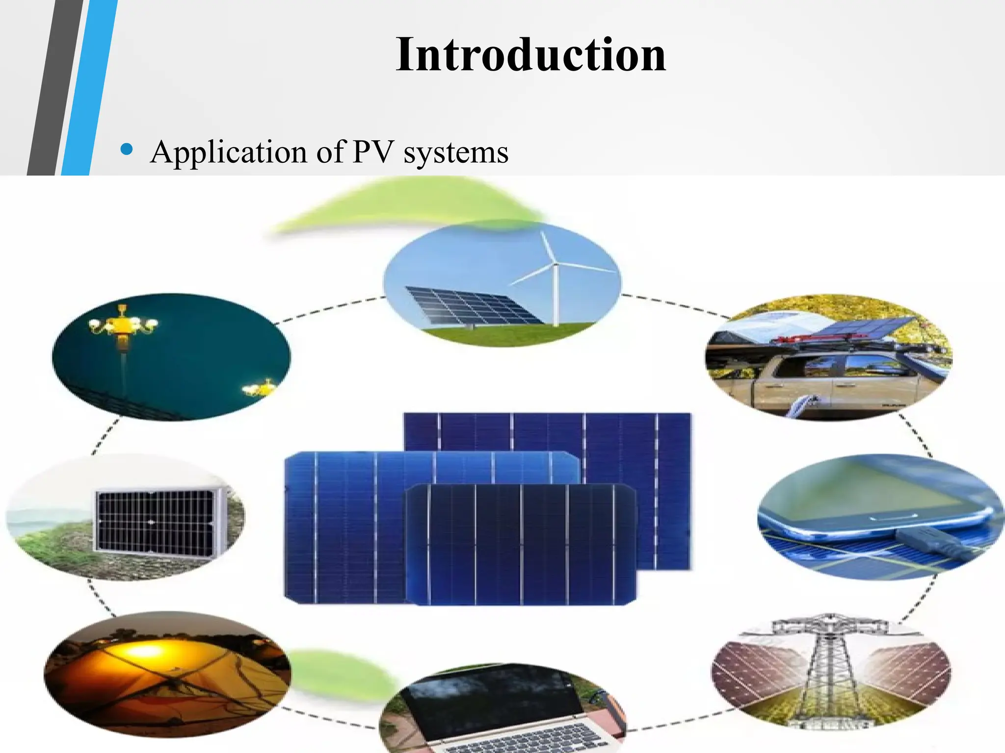
• Photovoltaic (PV)System, directly converts sunlight into
electricity.
Introduction
Not Consistent
4.
4
Advantages of PVsystem:
Locally Available
Clean Technology
Sustainability
Increasingly Cost-effective
Pollution free
Limitless source of energy
Introduction
7
The main aimbehind this research is to design an optimal
solution for the solar system. So, we need to design a control
scenario to make an efficient Centralized, and Distributed PV
system.
The efficiency of PV systems mainly dependent on
1. Efficiency of PV cells.
2. Efficiency of PV equipment
Introduction
8.
8
PV Equipment efficiency
PVequipment efficiency can be improved by solving two
main control problems.
i. Maximum power point tracking (DC-DC Converter)
ii. Inverter efficiency improvement
Introduction
14
Multiple PV modelsare reported. There are two commonly
used models.
• Single-Diode PV model
• Double-Diode PV model
Introduction
15.
15
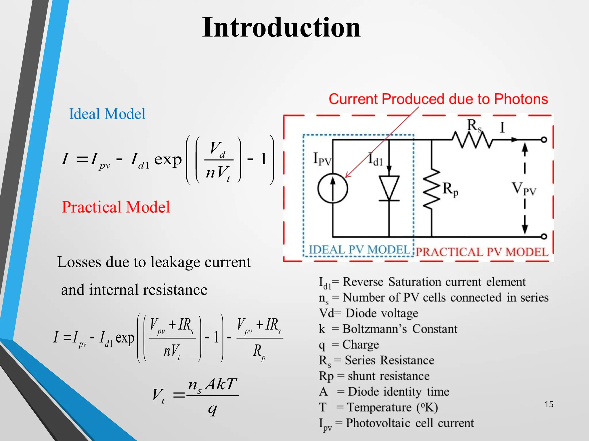
Losses due toleakage current
and internal resistance
Introduction
1 exp 1
d
pv d
t
V
I I I
nV
1 exp 1
pv s pv s
pv d
t p
V IR V IR
I I I
nV R
s
t
n AkT
V
q
16.
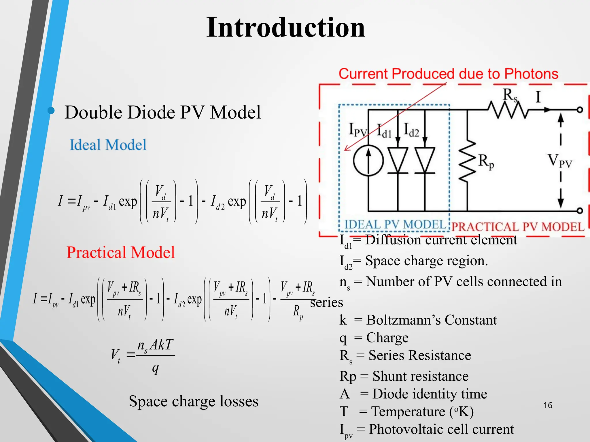
• Double DiodePV Model
Space charge losses 16
Introduction
1 2
exp 1 exp 1
d d
pv d d
t t
V V
I I I I
nV nV
1 2
exp 1 exp 1
pv s pv s pv s
pv d d
t t p
V IR V IR V IR
I I I I
nV nV R
s
t
n AkT
V
q
Id1
= Diffusion current element
Id2
= Space charge region.
ns
= Number of PV cells connected in
series
k = Boltzmann’s Constant
q = Charge
Rs
= Series Resistance
Rp = Shunt resistance
A = Diode identity time
T = Temperature (o
K)
Ipv
= Photovoltaic cell current
17.
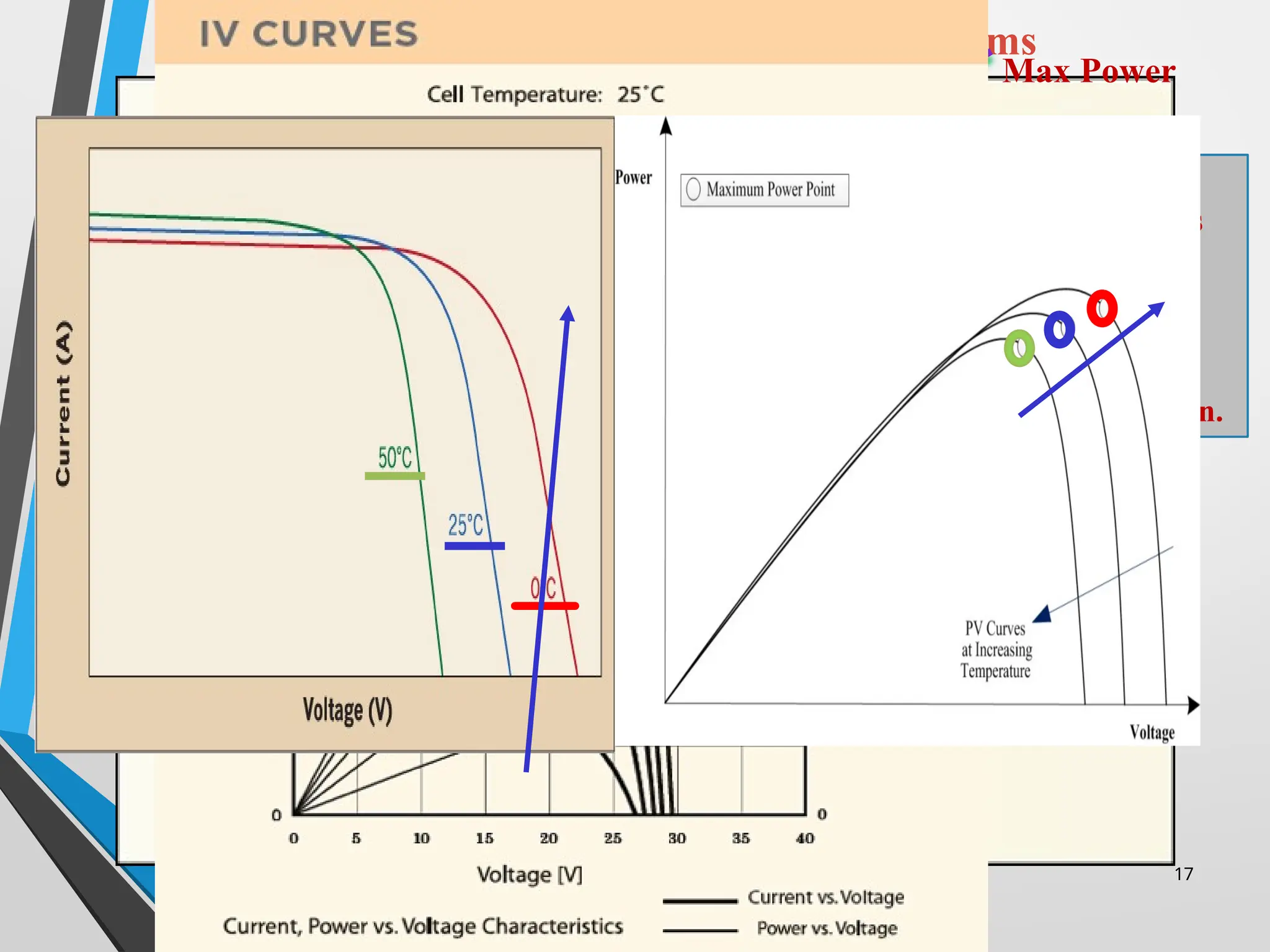
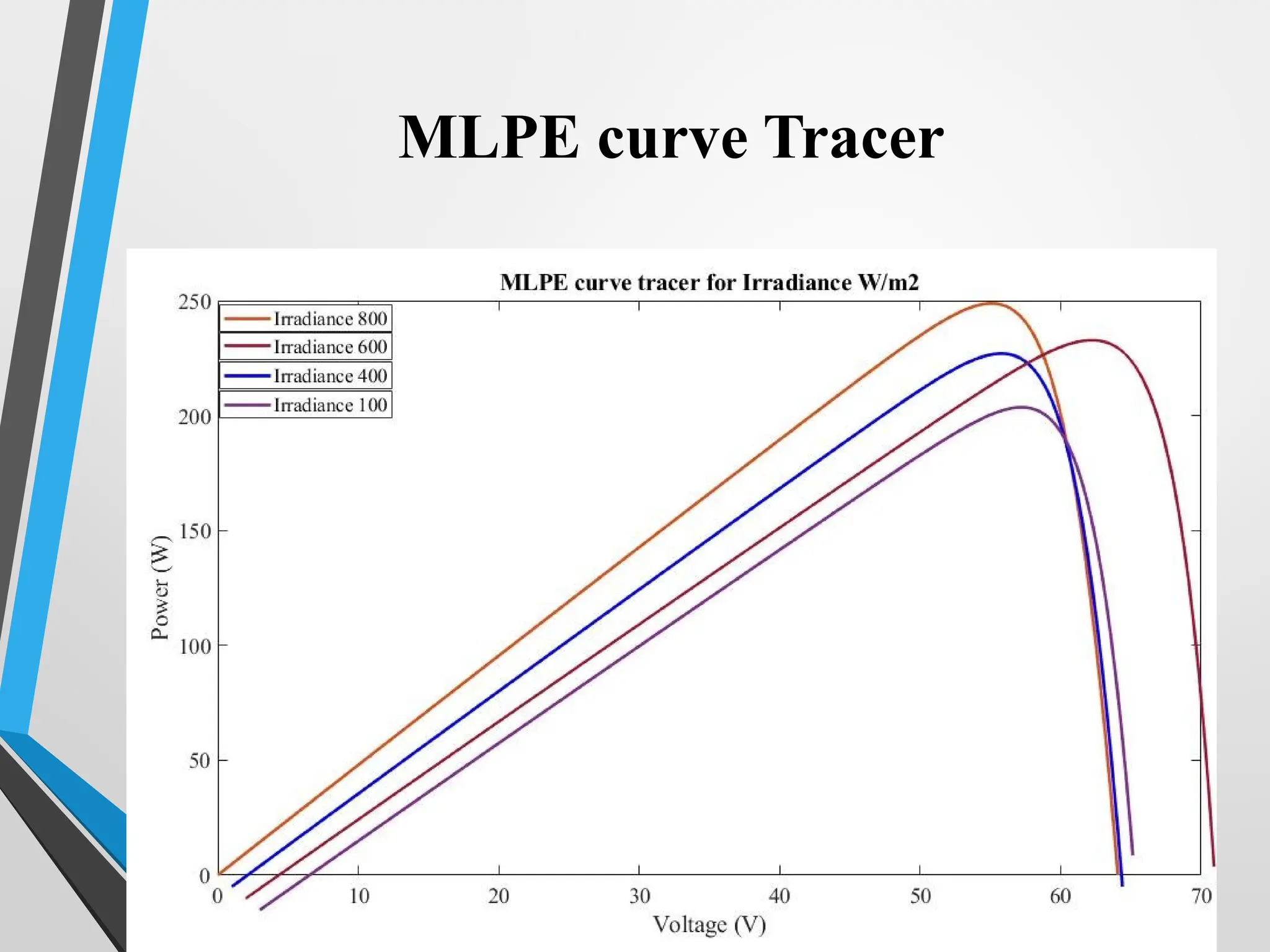
Photovoltaic Systems –Inherit Problems
Max Power
With changes in
weather conditions
like Irradiance &
Temperature.
This Maximum
Power Point also
changed its position.
17
18.
18
Introduction of MLPE
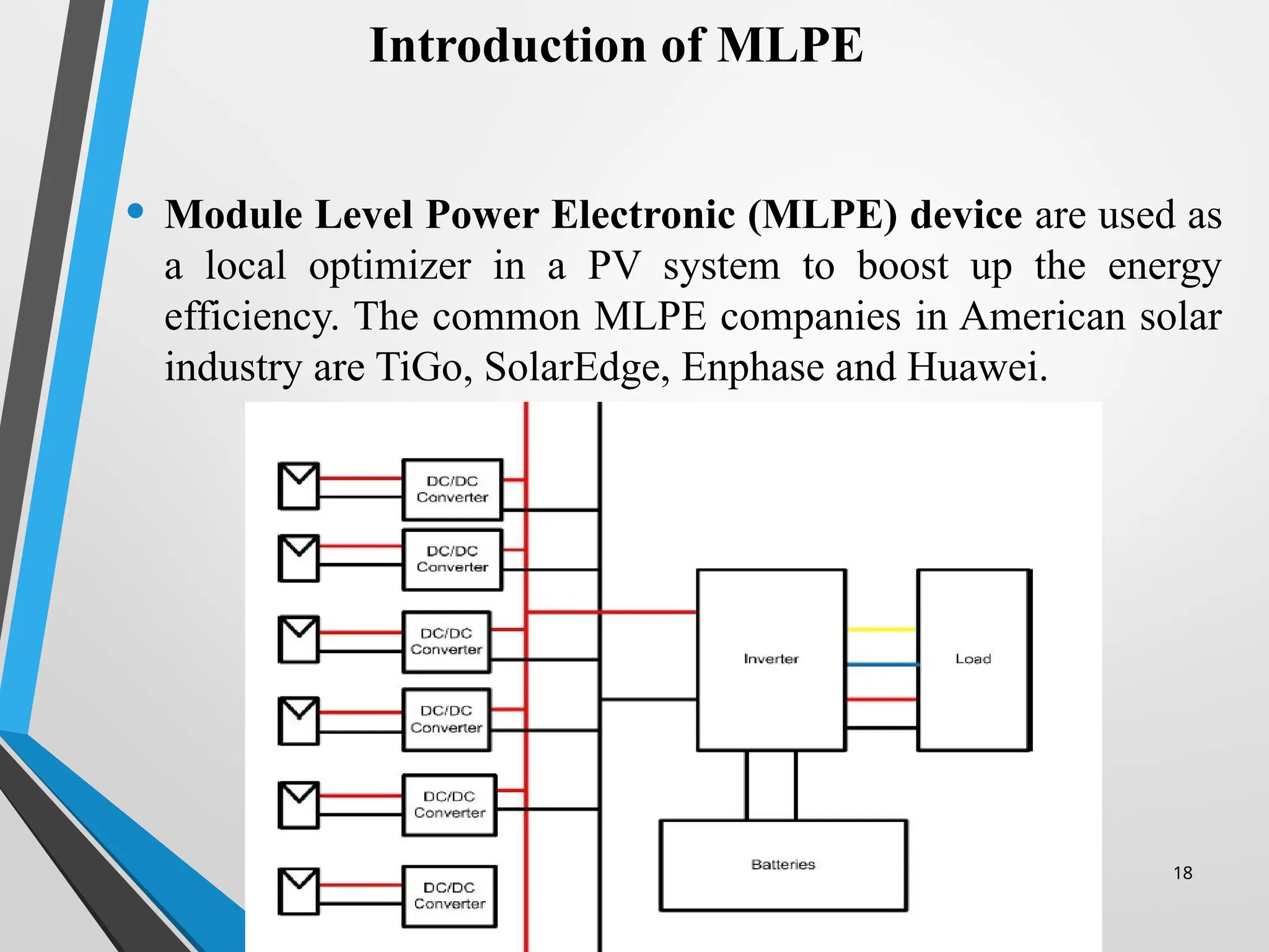
•Module Level Power Electronic (MLPE) device are used as
a local optimizer in a PV system to boost up the energy
efficiency. The common MLPE companies in American solar
industry are TiGo, SolarEdge, Enphase and Huawei.
19.
19
• MLPE suchas DC power optimizers and micro-inverters can
reduce the impact of shading losses, multiple roof planes,
and module mismatch on PV system performance.
• MLPE can also help meet recent National Electrical Code
(NEC) requirements for rapid shutdown of energized PV
circuits.
• MLPE technologies (in conjunction with optional
communication gateways) can allow for module-level
performance monitoring and diagnostics.
• Warranties for MLPE products are typically longer than
conventional central or string inverters.
Introduction of MLPE
20.
20
Advantages and Disadvantagesof MLPE
There are three major advantages of MLPE devices.
• The losses due to partial shading, panel orientation or tilt angles and
multiple types of PV module in a single string are minimized at
modular level.
• Modular level output power will be monitored by the consumer and
service provider.
• Rapid shutdown facility is available to the consumer which can be used
in emergency situations..
However, some disadvantages of utilizing these devices are
• Number of devices are increase and this will compromise the reliability
of the system. Device count will also increase the losses due to lose
connection or device malfunction problems.
• Furthermore, even in uniform irradiance condition this device will
keep on consuming power without any additive benefit.
21.
21
This research workis divided into different research problems.
• The main problem that we have to face nowadays is the
efficiency loss of the Solar panel that can be created from the
shading condition due to the environment for that means the
device MLPE help to achieve 25 to 35% power during the
shading time and this device not bypass the whole module.
• The other main problem is the efficiency and connection of
the device. The connection means that we have to see the
feasible with the converter or not. And the efficiency of
different manufacturers has a different impact so comparison
of efficiency is also a big challenge in the solar MLPE system.
Problem Statement
22.
22
• Depleting fossilfuels rises a deep threat to meet the demand and supply of
electric energy and has also impact on environmental pollution. Due to
environmental effects, in the world many countries are switching over from
fossil fuels to Renewable Energy Sources (RES) that are environmentally
friendly energy sources. In PV system, main problem is the varying nature of
sun that causes the losses in the efficiency of PV system which occur due to
partial shading conditions..
• Solar PV system is the most emerging technology of the world. There are three
types of PV systems which are commonly used in PV market i.e., string
inverter, micro inverter, and inverter with power optimizer. String inverter is
the most used technology because it is efficient and cost effective. In a string
inverter all PV modules are connected in series in the form of a string. There
are some technical issues in it. If there is partial shading in the PV module then
that PV module is bypassed, and output of the string is reduced. So, to resolve
these issues Modular Level Power Electronic (MLPE) devices are introduced.
Literature Survey
23.
23
Literature Survey
The commonlyused MLPE devices are Modular Level Inverter
(MicroInverter) and Modular Level Converter (Power Optimizer). MLPE
devices resolve both issues of string inverter, but these systems are costly.
Another additive advantage is that an MLPE device can provide modular
level rapid shutdown (Safety Feature), design flexibility, and Modular
Level energy monitoring, remote management, and troubleshooting.
However, the only technical issue in these systems are they are component
intensive and complex. So, the reliability of the system is compromised.
The leading companies which develop power optimizers are:
• SolarEdge
• TiGO
• Huawei.
• Enphase
24.
24
Literature Survey Shadingin
MLPE
• The first scenario represents an optimal installation where all
PV panels have the same irradiation and no shadows occur.
• The second scenario simulates a niche application where one
PV-module has always a different irradiation than the others.
This is achieved by covering one module with a thin and
semi-transparent blanket, while the remaining modules of
each string have the full irradiation
• The third scenario simulations a situation where a small
shadow moves over the panels during the day.
25.
25
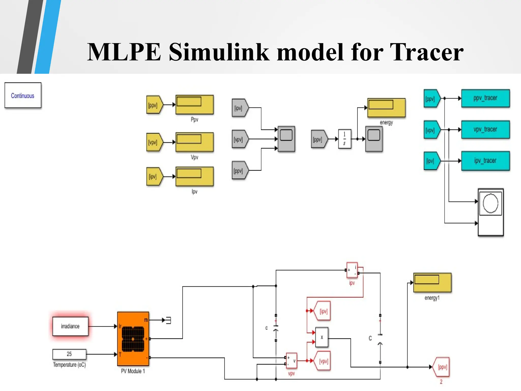
• Development ofa Simulink MPPT algorithm for
tracking the optimal output power for Distributed PV
system in all weather conditions such as uniform and
partial shaded conditions.
• Design a Simulink model of a modular level DC-DC
converter.
• Development of energy monitoring, troubleshooting,
and rapid shutdown parameters with the design
Simulink.
• Compute the Efficiency of Power optimizer during
shaded cases with the help of software.
Objectives
26.
26
MPPT techniques
• Theexperimental techniques which is discussed to proof
the MLPE distributed PV system give the better results as
compare to the centralized system are as follows
• Dragonfly
• Cuckoo’s Search
• Incremental Conductance
• Perturb & Observe
12/15/2025 29
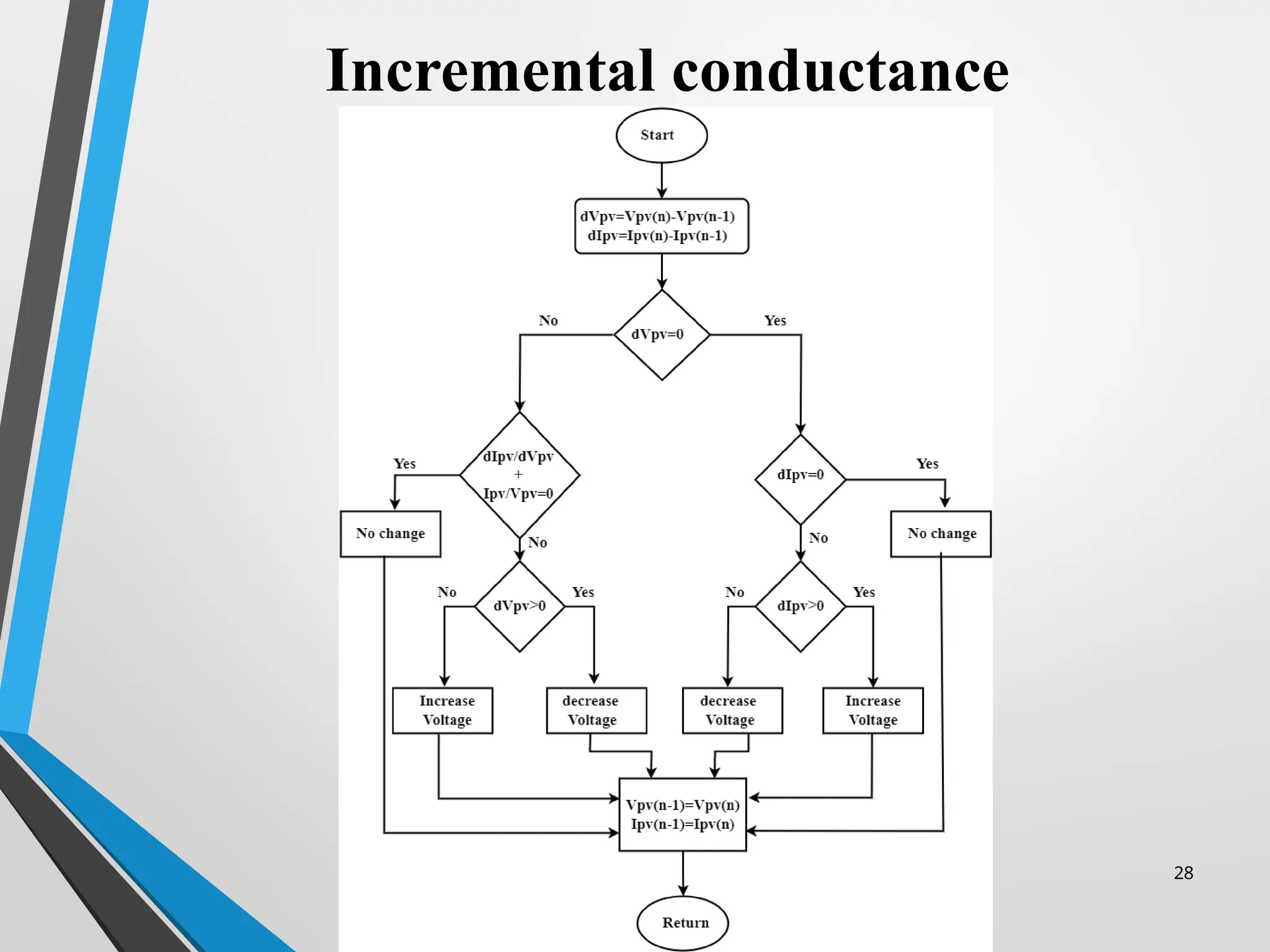
• Asin MPP the derived current with respect to voltage is zero.
•
• By rearranging the above equation
• Here (∆I) and (∆V) are the increments of P-V current and the voltage,
respectively. These are rules for InC which is described as below:
• At MPP
• , left of MPP
• Right MPP
Incremental conductance
30.
30
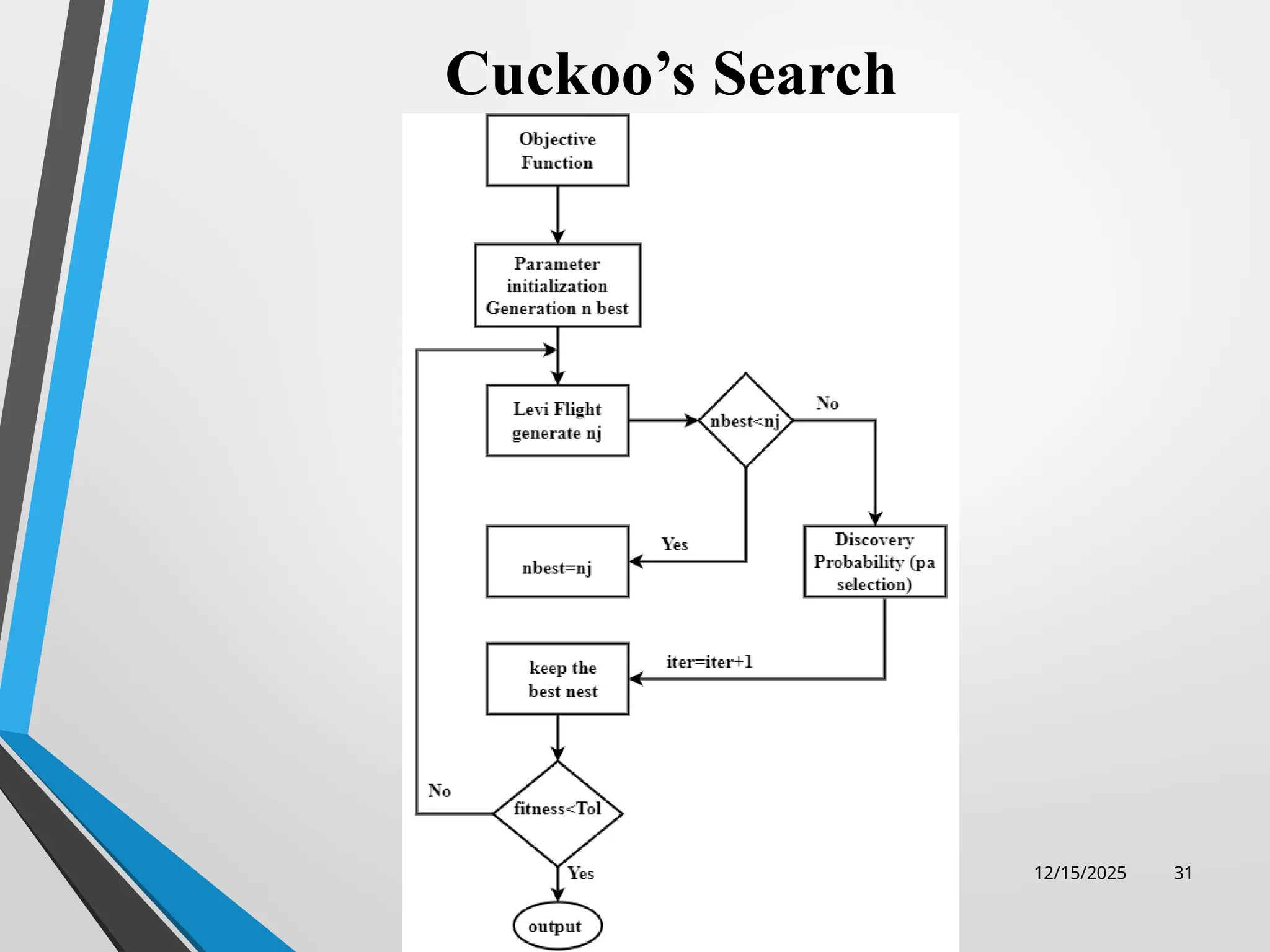
Cuckoo’s Search
The CSAconcepts are stated below.
• Cuckoos are social creatures who live in groups.
• Cuckoos recall where they hid in the past.
• Steal by following the other Cuckoos.
• Cuckoos defend their hiding areas from the elements
• Lévy flights are often used in clustering algorithm, which
differs from other algorithms since the host birds may quit
their nests & fly away if they feel their eggs have been
altered or polluted
32
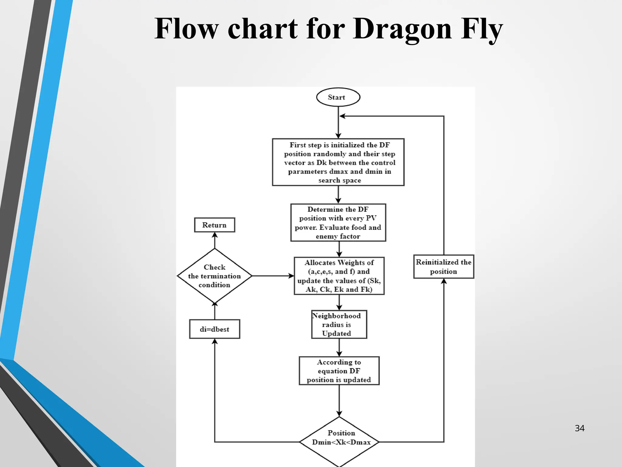
Dragon Fly algorithm
•First step is the Separation of the dragon fly which means that any DF
does not collapse with other fly. In case of static swam, donates the
current position of the dragonfly where position donated by k-th.
Separation Sk for individuals kth
can be calculated with Sk =(Q-QN),
where Q,QN represents the Nth neighboring DF and X is the total number
of individual neighboring.
• 2nd
step is the alignment which shows the velocity of the DF matches
with the indiviuals in the same neighbor where Alignment can be
represented by Aj and it can be calculated as.Vk. Where Vk is the velocity
of the k-th neighboring DF.
• 3rd
step is the cohesion which means the ability of the DF to move about
the mid-point of the mass of neighbors. Cohesion can be represented by
Ck and it can be written as equation Ck=-Q. where Q denote the real
position of DF’s individual and QN represent the Nth
position of the
neighboring DF.
33.
33
Dragon Fly purposedtechniques
• 4th
step is the food the individuals of DFs move towards food which is
most important for the sake of survival. The attraction of food for the
DFs can be found out as Fk at position y is shown Fk =Qfood+ Q. The
position of located food is represented by Qfood & Q stands for the
current individual’s position.
• 5th
step is the Enemy as clear from the name of the enemy that every
individual move away from the enemy and their equation can be
represented as Ek=Qenemy+Q. Where Qenemy shows the position of the
enemy and Q shows the located individual position. These five sources
finalize the current individual’s position. And final upgraded position
can be calculated as Qk=Qk+ΔQ. The values of ΔQ can be find out as
• ΔQk = WΔQk + (sSk + aAk + cCk + f Fk + eEk)………….(1)
35
Result & discussion
•The result can be made with the help of the Matlab Simulink software and
Helioscope designing tools.
• We have to design two systems such as centralized and DMPPT on the
Matlab and helioscope for the sake of better efficiency and optimized
result.
• Different algorithm such as dragonfly, cuckoo’s search, perturb and
observe method, and incremental conductance can be compared under the
case of centralized and distributed PV system .
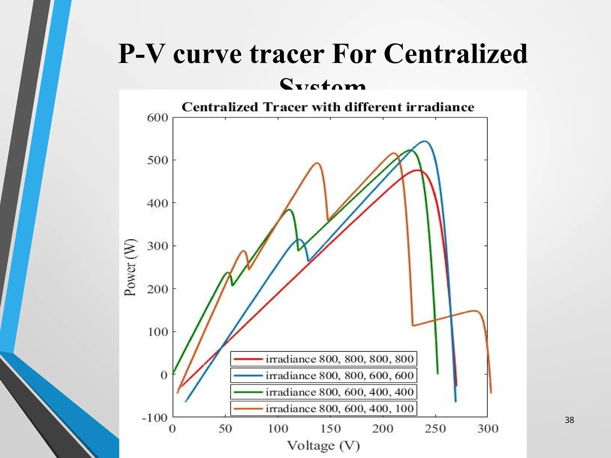
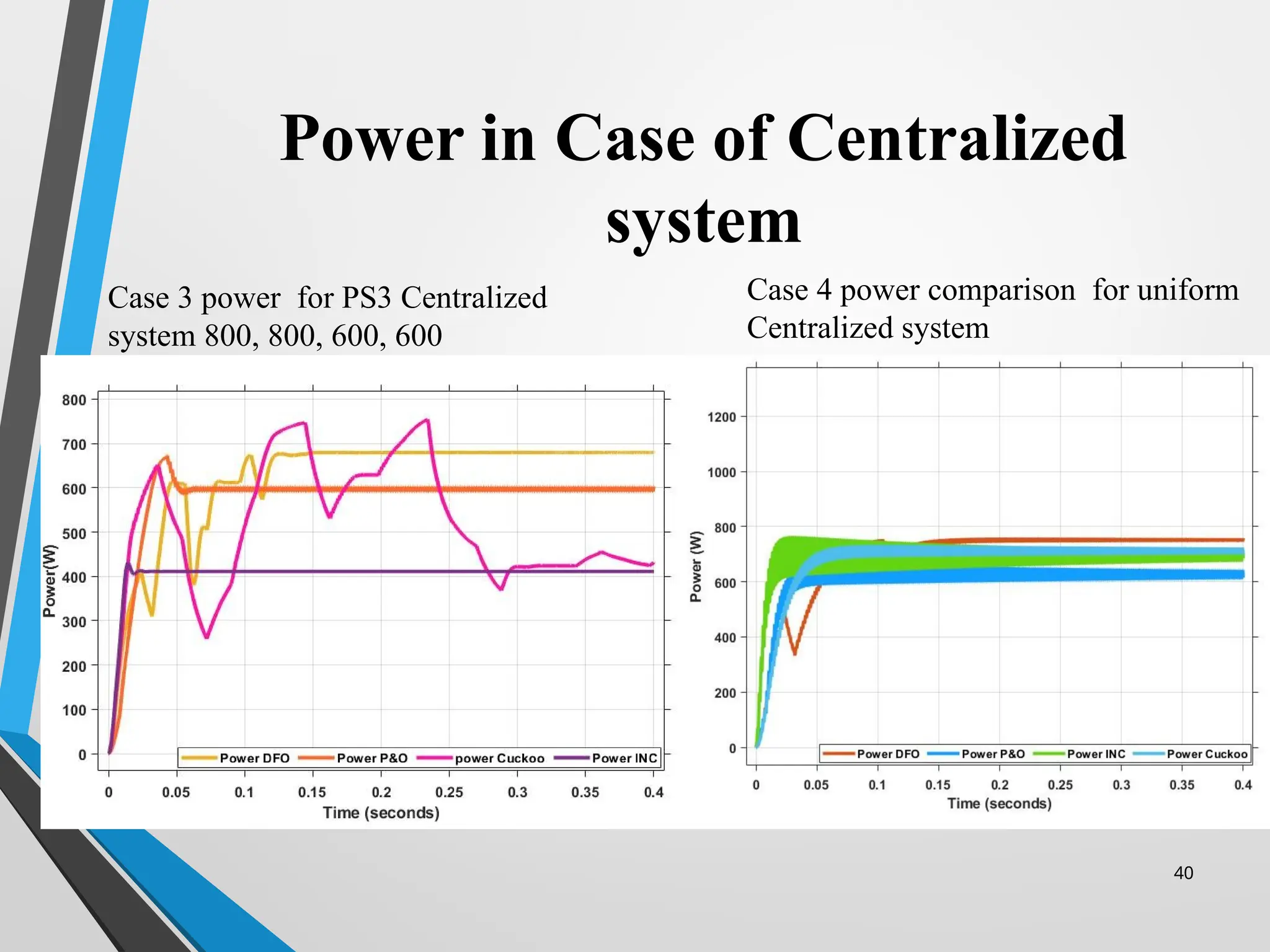
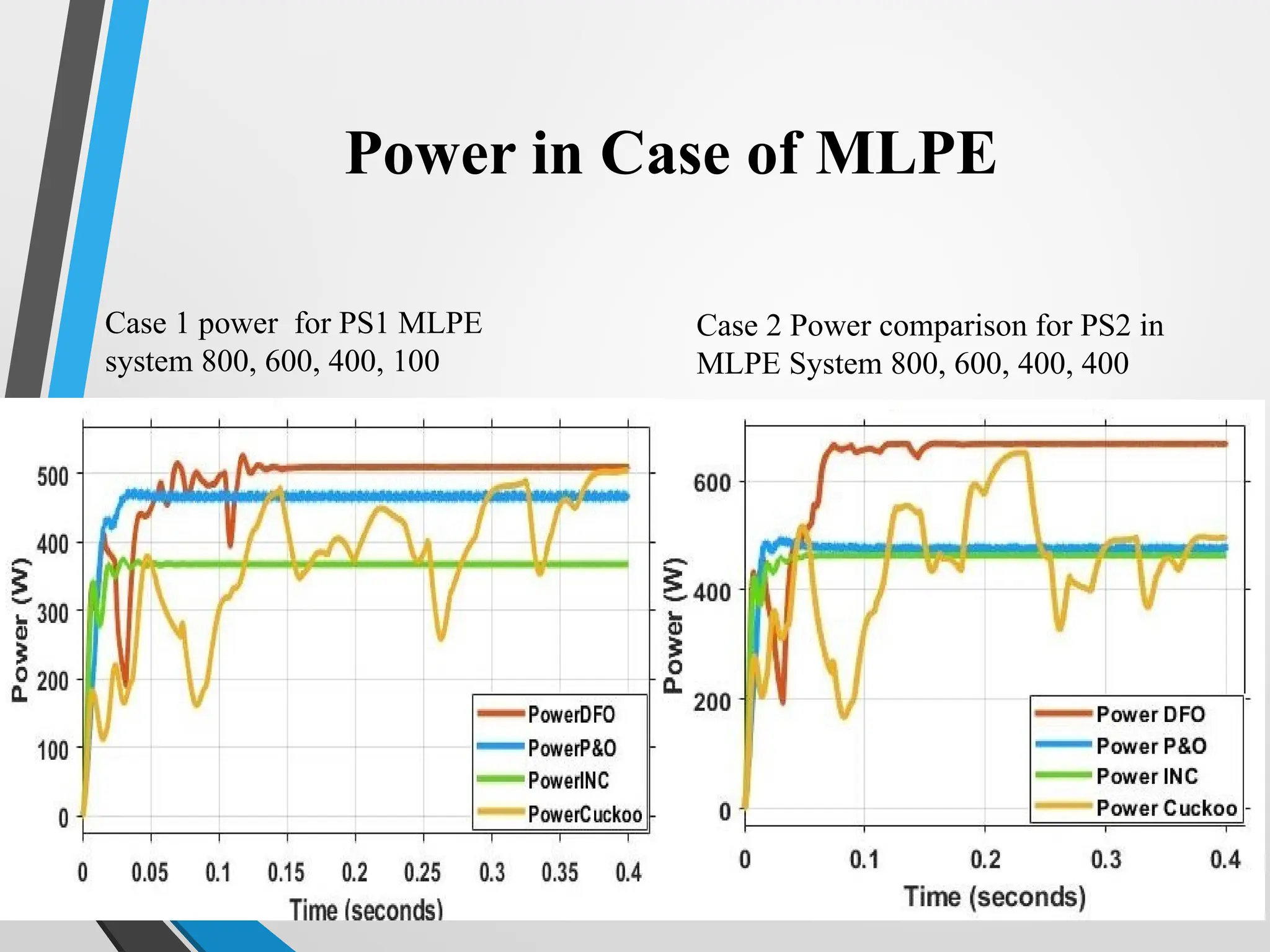
• The result can be divided into four different cases. Partial shading and
uniform cases are as under. Case 1 describe the partial shading such as
800, 600, 400 and 100. Case 2 describe the partial shading 800, 600, 400
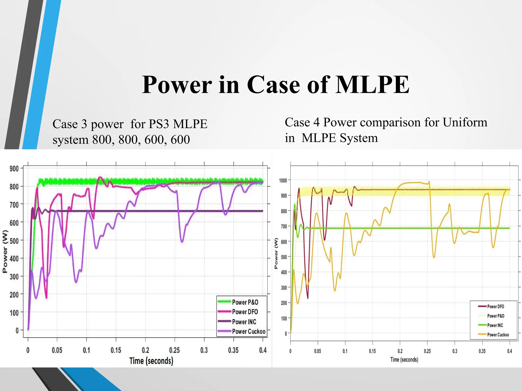
and 400. Case 3 describe the shading on two panels such as 800, 800, 600,
and 600. Case 4 describe the uniform irradiance on all panels.
39
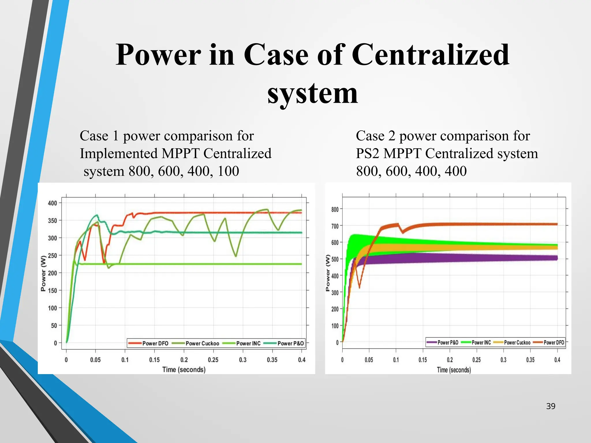
Power in Caseof Centralized
system
Case 1 power comparison for
Implemented MPPT Centralized
system 800, 600, 400, 100
Case 2 power comparison for
PS2 MPPT Centralized system
800, 600, 400, 400
40.
40
Power in Caseof Centralized
system
Case 4 power comparison for uniform
Centralized system
Case 3 power for PS3 Centralized
system 800, 800, 600, 600
41.
41
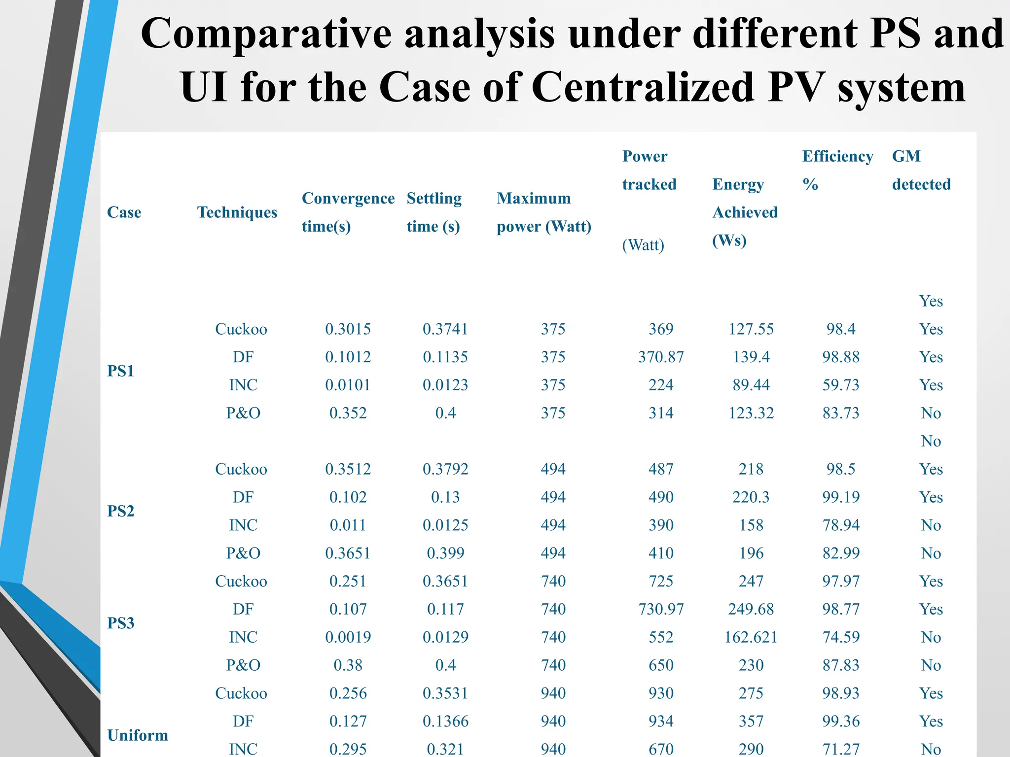
Comparative analysis underdifferent PS and
UI for the Case of Centralized PV system
Case Techniques
Convergence
time(s)
Settling
time (s)
Maximum
power (Watt)
Power
tracked Energy
Achieved
(Ws)
Efficiency
%
GM
detected
(Watt)
PS1
Cuckoo
DF
INC
P&O
0.3015
0.1012
0.0101
0.352
0.3741
0.1135
0.0123
0.4
375
375
375
375
369
370.87
224
314
127.55
139.4
89.44
123.32
98.4
98.88
59.73
83.73
Yes
Yes
Yes
Yes
No
No
PS2
Cuckoo
DF
INC
P&O
0.3512
0.102
0.011
0.3651
0.3792
0.13
0.0125
0.399
494
494
494
494
487
490
390
410
218
220.3
158
196
98.5
99.19
78.94
82.99
Yes
Yes
No
No
PS3
Cuckoo
DF
INC
P&O
0.251
0.107
0.0019
0.38
0.3651
0.117
0.0129
0.4
740
740
740
740
725
730.97
552
650
247
249.68
162.621
230
97.97
98.77
74.59
87.83
Yes
Yes
No
No
Uniform
Cuckoo
DF
INC
0.256
0.127
0.295
0.3531
0.1366
0.321
940
940
940
930
934
670
275
357
290
98.93
99.36
71.27
Yes
Yes
No
45
Power in Caseof MLPE
Case 1 power for PS1 MLPE
system 800, 600, 400, 100
Case 2 Power comparison for PS2 in
MLPE System 800, 600, 400, 400
46.
46
Power in Caseof MLPE
Case 3 power for PS3 MLPE
system 800, 800, 600, 600
Case 4 Power comparison for Uniform
in MLPE System
47.
47
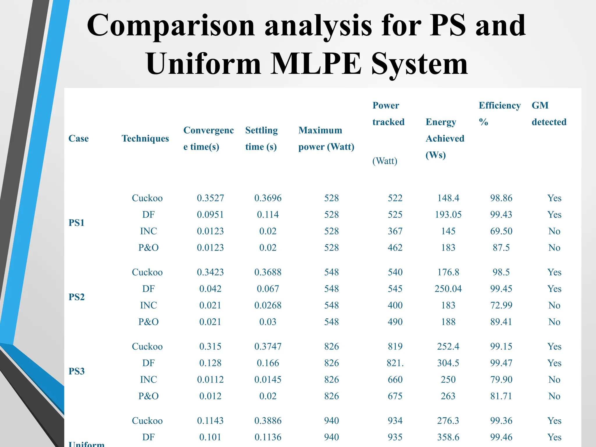
Comparison analysis forPS and
Uniform MLPE System
Case Techniques
Convergenc
e time(s)
Settling
time (s)
Maximum
power (Watt)
Power
tracked Energy
Achieved
(Ws)
Efficiency
%
GM
detected
(Watt)
PS1
Cuckoo
DF
INC
P&O
0.3527
0.0951
0.0123
0.0123
0.3696
0.114
0.02
0.02
528
528
528
528
522
525
367
462
148.4
193.05
145
183
98.86
99.43
69.50
87.5
Yes
Yes
No
No
PS2
Cuckoo
DF
INC
P&O
0.3423
0.042
0.021
0.021
0.3688
0.067
0.0268
0.03
548
548
548
548
540
545
400
490
176.8
250.04
183
188
98.5
99.45
72.99
89.41
Yes
Yes
No
No
PS3
Cuckoo
DF
INC
P&O
0.315
0.128
0.0112
0.012
0.3747
0.166
0.0145
0.02
826
826
826
826
819
821.
660
675
252.4
304.5
250
263
99.15
99.47
79.90
81.71
Yes
Yes
No
No
Cuckoo
DF
0.1143
0.101
0.3886
0.1136
940
940
934
935
276.3
358.6
99.36
99.46
Yes
Yes
48.
48
HelioScope Results
• Inthis software different companies can be compared such
as enphases SMA, Solar edge, Huawei, Tigo.
• These companies can be compare with respect to the
centralized and MLPE / power optimizer under tested with
the different irradiance conditions.
• The result can be made on 0.25MW system have simple
string inverters and MLPE inverters and converters.
49.
49
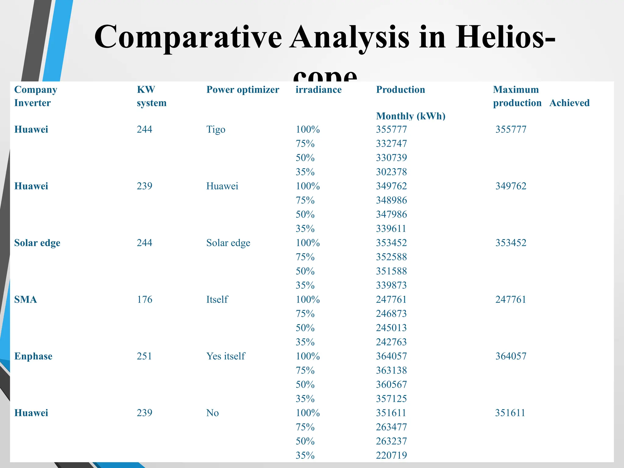
Comparative Analysis inHelios-
cope
Company
Inverter
KW
system
Power optimizer irradiance Production Maximum
production Achieved
Monthly (kWh)
Huawei 244 Tigo 100% 355777 355777
75% 332747
50% 330739
35% 302378
Huawei 239 Huawei 100% 349762 349762
75% 348986
50% 347986
35% 339611
Solar edge 244 Solar edge 100% 353452 353452
75% 352588
50% 351588
35% 339873
SMA 176 Itself 100% 247761 247761
75% 246873
50% 245013
35% 242763
Enphase 251 Yes itself 100% 364057 364057
75% 363138
50% 360567
35% 357125
Huawei 239 No 100% 351611 351611
75% 263477
50% 263237
35% 220719
50.
12/15/2025 50
Conclusion
• ComparisonBetween Centralized and distributed is
shown in this research.
• Find Distributed Give better result during the shading
Conditions.
• DF Algorithm Give the better Results.
#1 Bismillah Hir Rahman Nir Raheem Aslamualaikum
My name is Muhammad Talha Naveed, My supervisor name is Dr Muhammad Yaqoob javed my research topic is Module level power electronics in distributed power system for solar Application
#2 I organized my presentation as follow First I will give the introduction of my topic
Then I talk about problem statement followed by the literature survey
next I will describe the objective of my research topic then I will elaborate the methodology
After that I mention the estimated time line , references are mention at the end
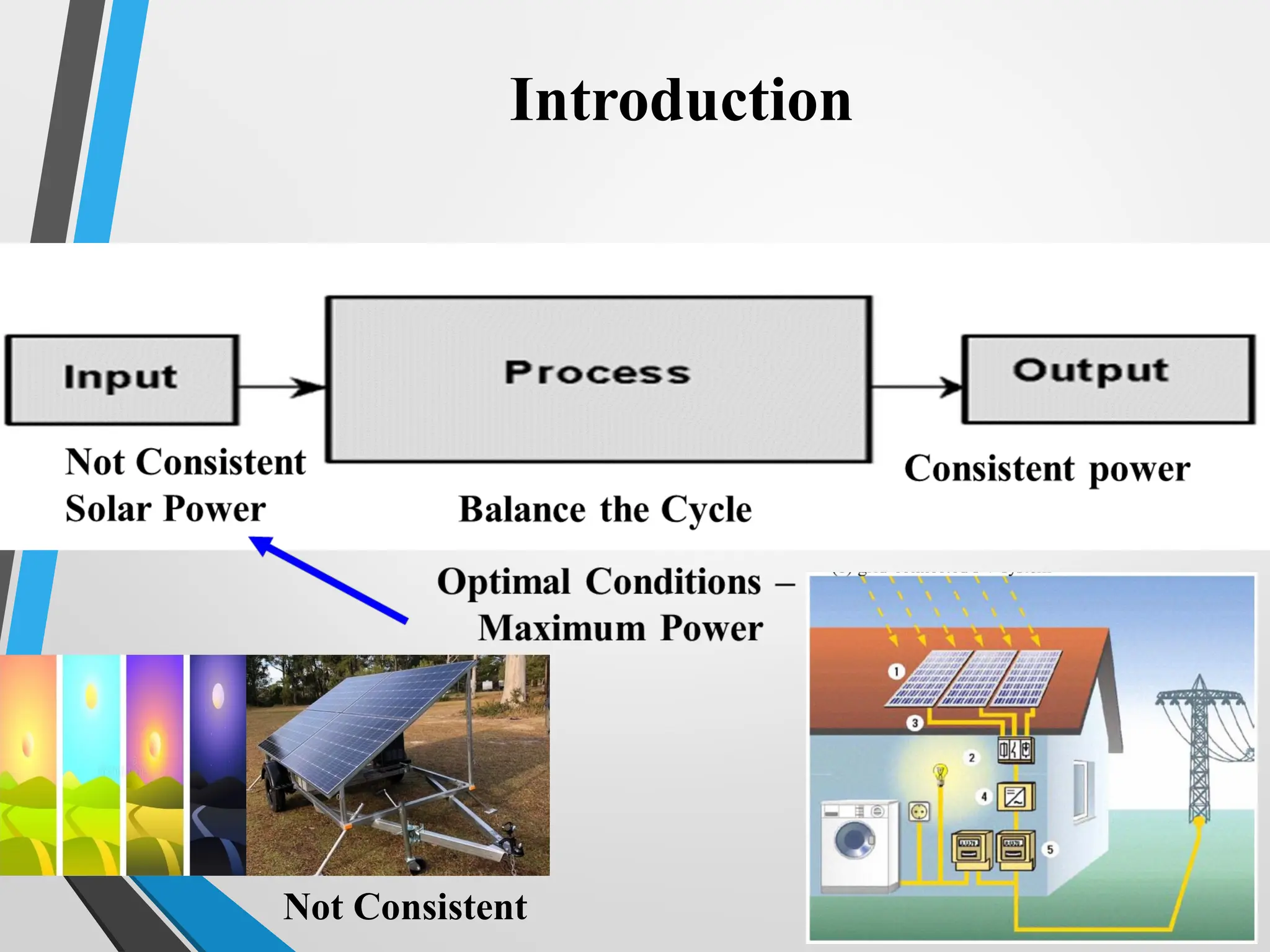
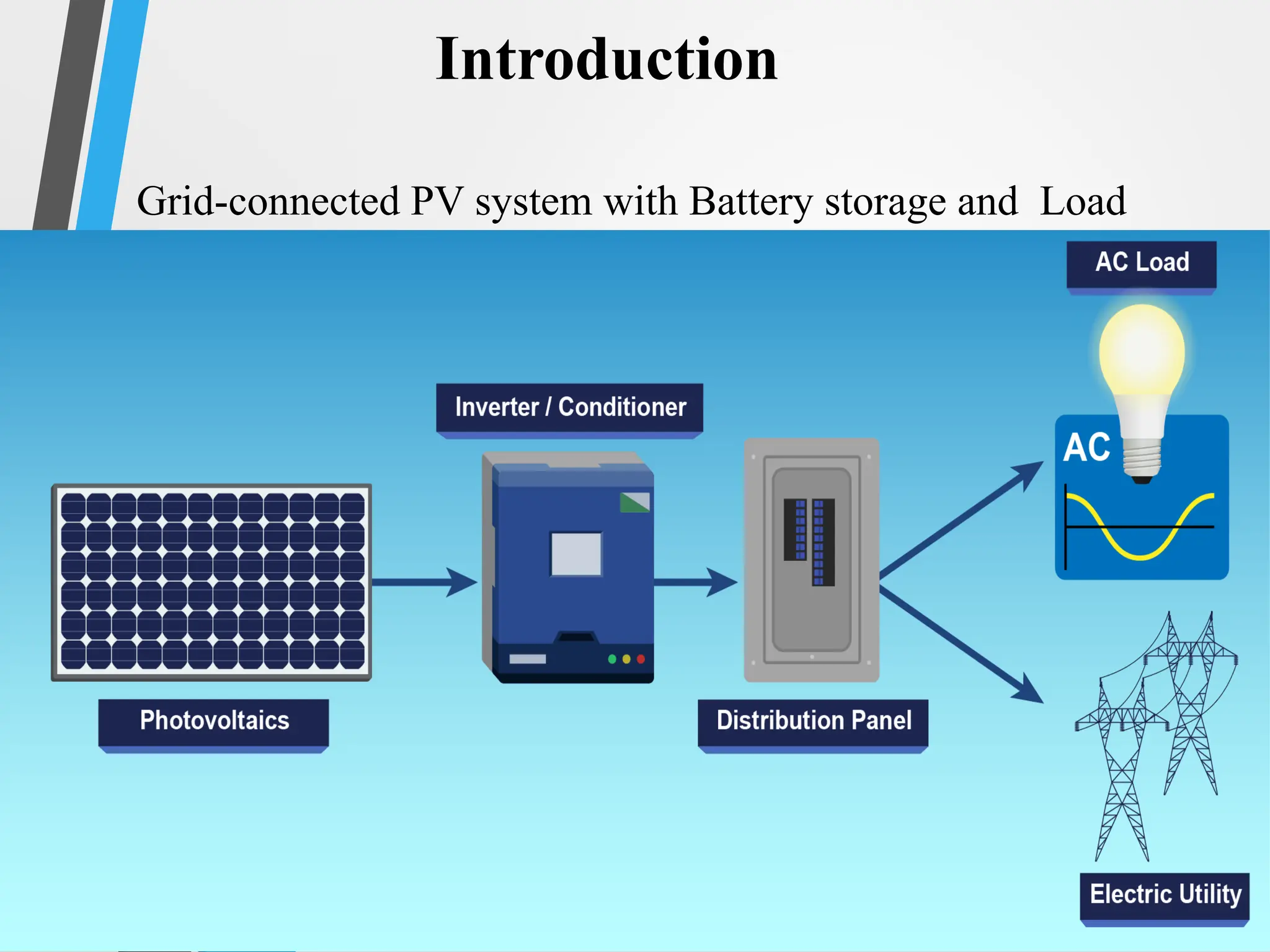
#3 There are Two Types of Solar Energy.
1. Photovoltaic (PV) System converts sunlight into electricity using panels made of semiconductor cells 2. Solar thermal technology, which captures the sun's heat.
The input power of solar is not consistent due to varying nature of sun , while we require consistent output power of solar for grid station or consumer
So, we need a process to balance the input and output cycle of solar power at optimal conditions that gives maximum power
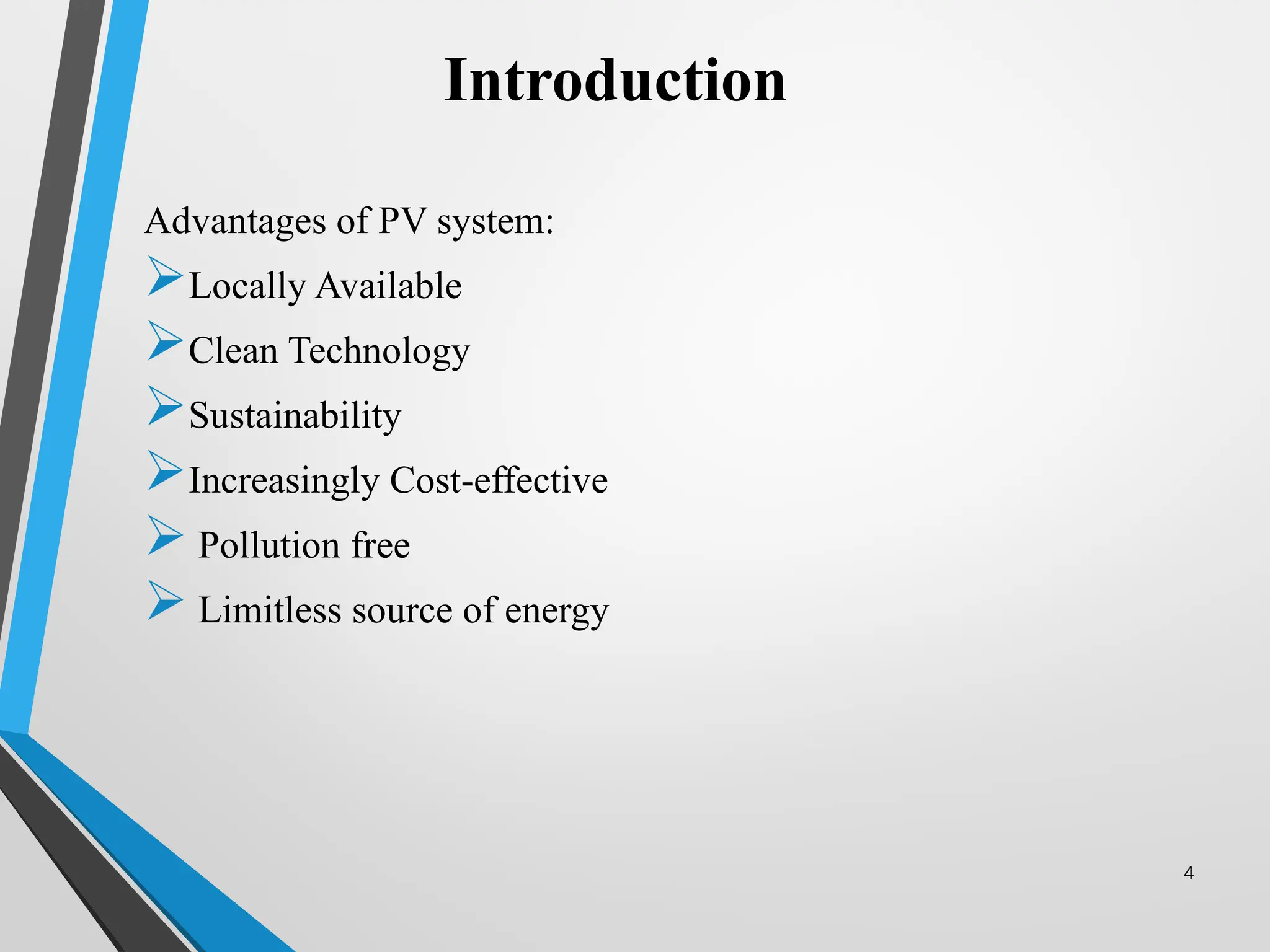
#4 Solar power has various advantages to other renewable source of energy that are
Locally Available
Clean Technology
Sustainability
Increasingly Cost-effective
Pollution free
Limitless source of energy
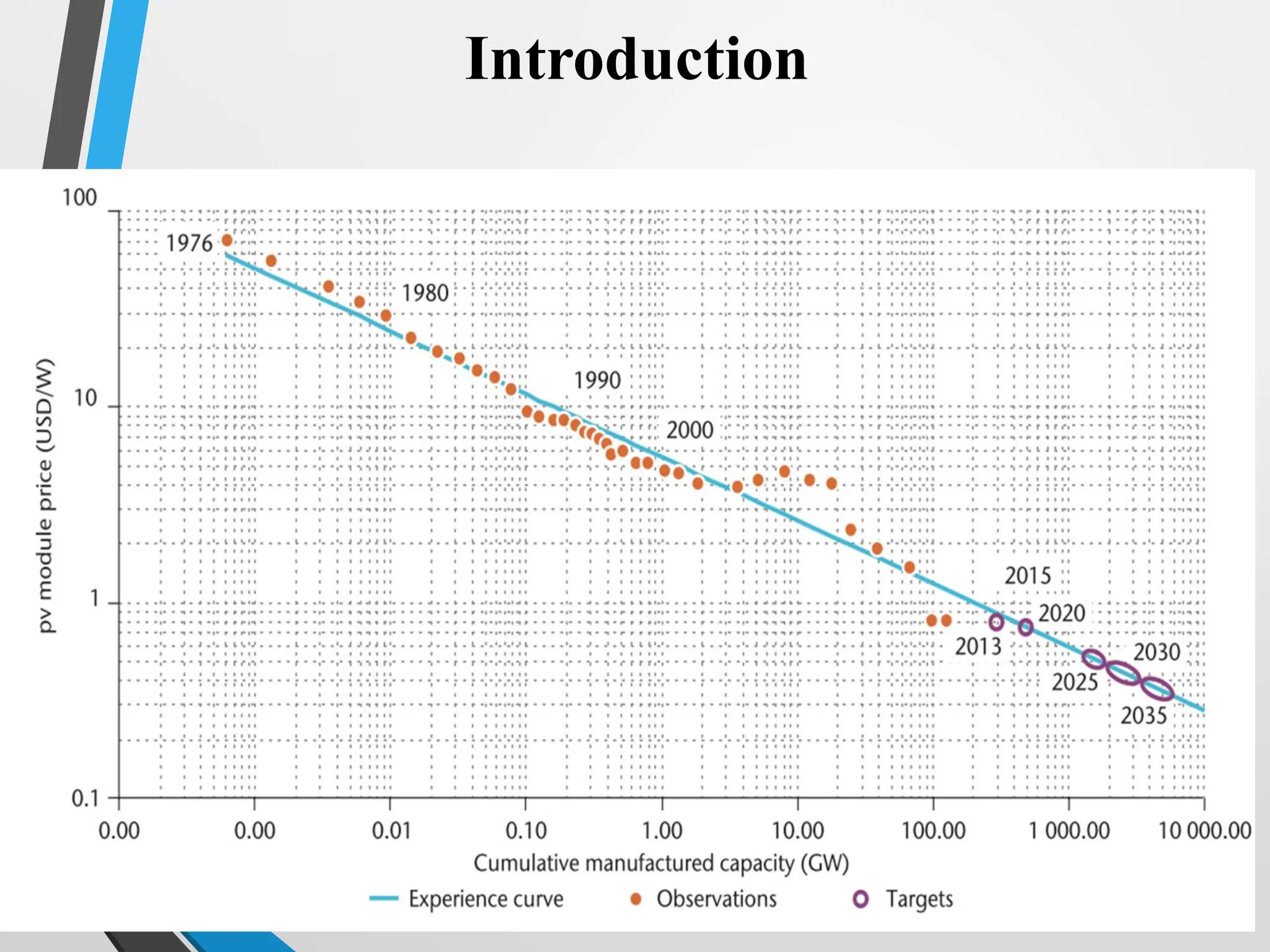
#5 With the passage of time as we see in 1976 per watt cost of pv module 80 dollar nd in 2020 it is round about 50 cent
#6 It can be used
a. Independent solar power plant b. building integrated pv system c. electrification parking system d. Electric vehicle with solar panel c e. robotics f. aero plane g. satellite h. street light
#7 The major issue in pv system is to improve the efficiency of pv system
in order to get the most efficient pv system
We need to improve the efficiency of solar cell or efficiency of pv cell improve by changing the material and it is not our research domain
So our focus will the efficiency of the pv equipment
#8 PV equipment efficiency can be improved by solving two main control problems.
Maximum power point tracking
Inverter efficiency improvement
we will control the switch of DC to DC converter. So, it should be accurate, fast and simple to implement.
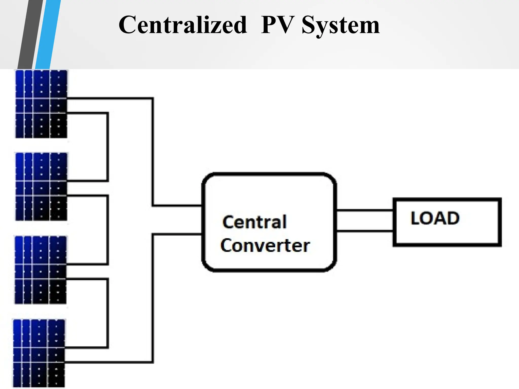
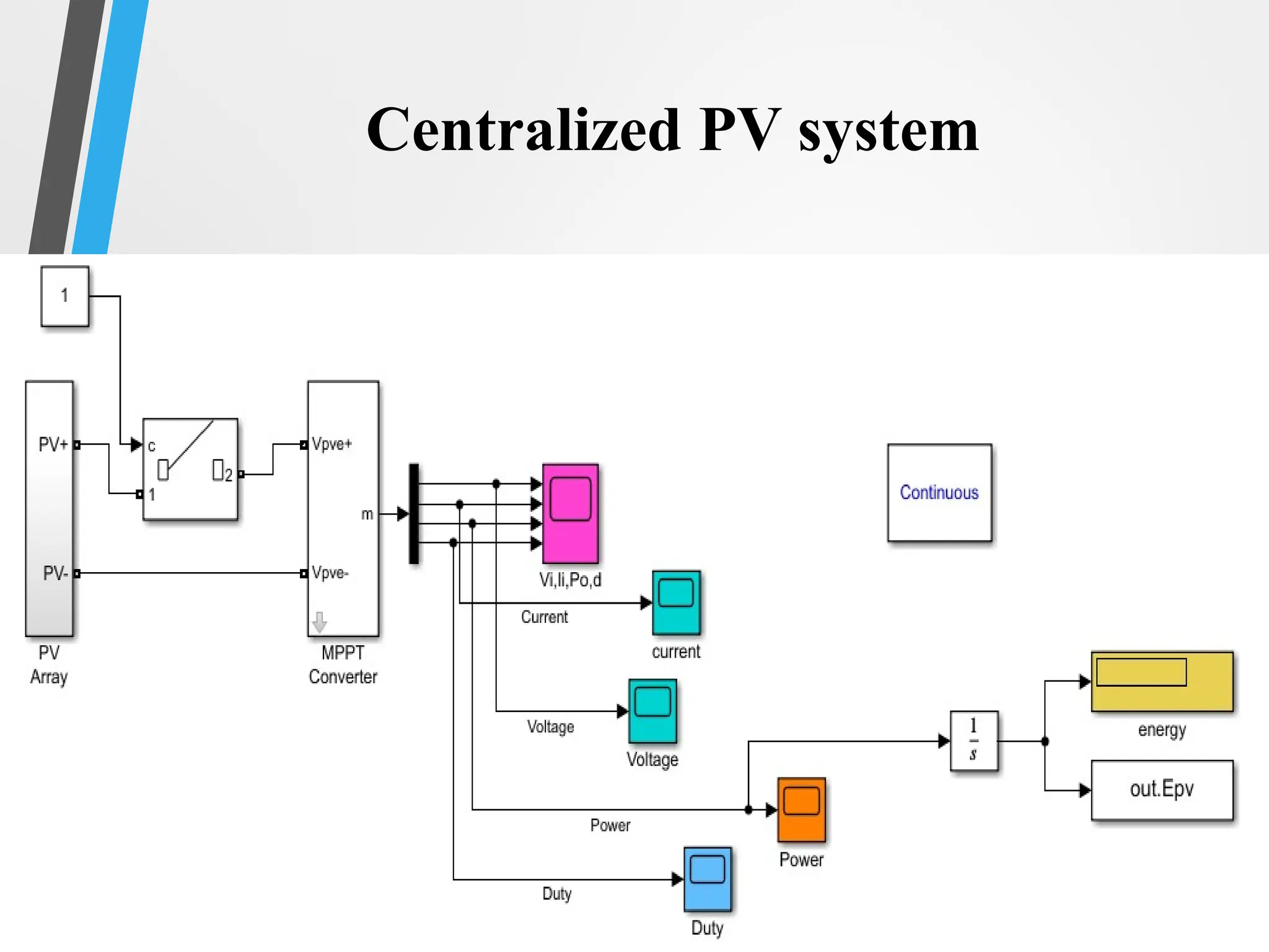
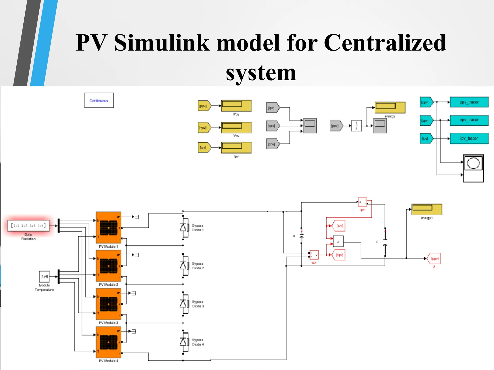
#11 PV system can be configured in two type of topology one is centralized and second is distributed pv system.
In centralized PV system multiple panel are connected then a single dc to ac converter are connect with grid
#12 PV system can be configured in two type of topology one is centralized and second is distributed pv system.
In centralized PV system multiple panel are connected then a single dc to ac converter are connect with grid
all the dc dc converter are connected to a single dc-ac converter
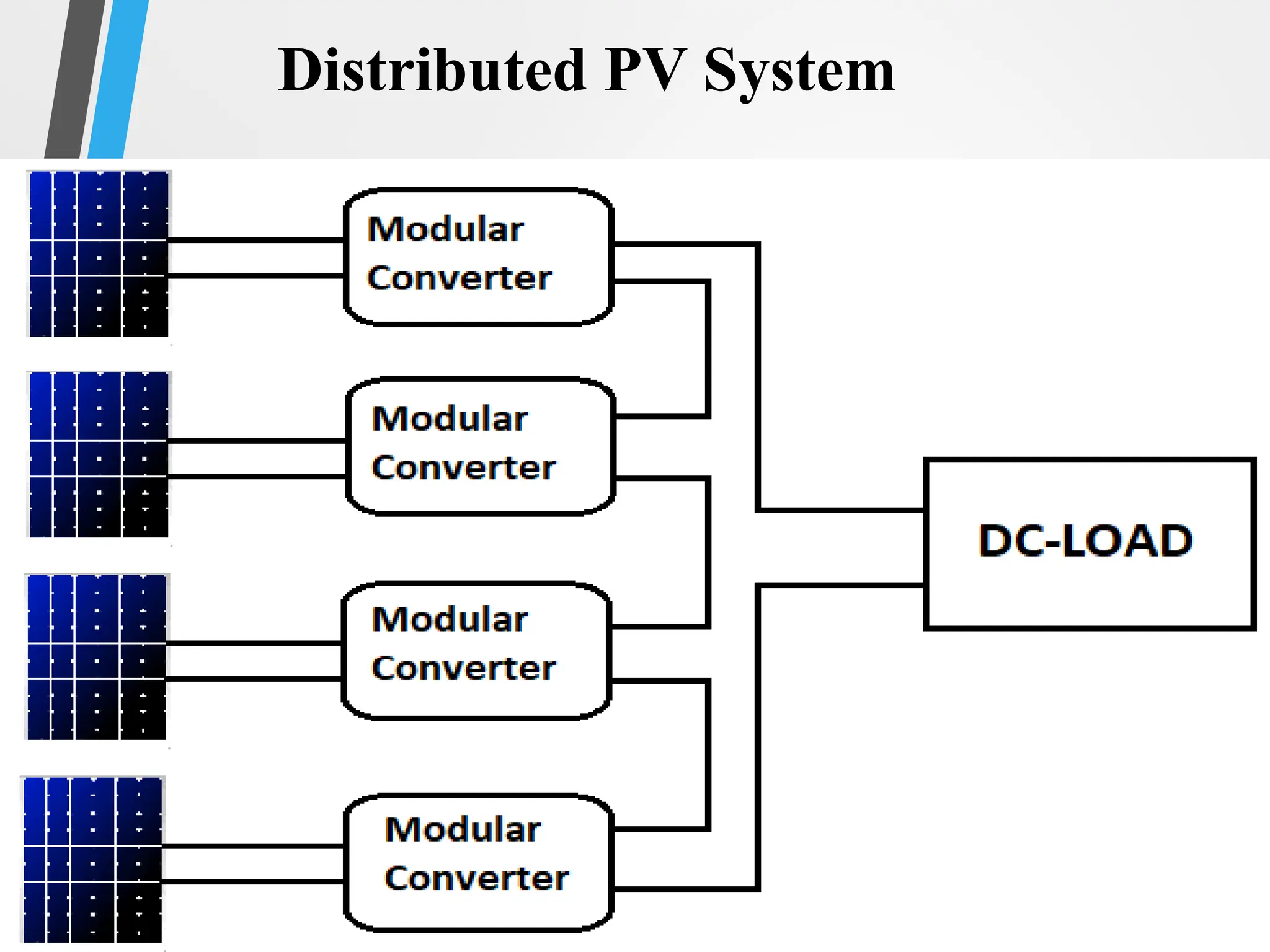
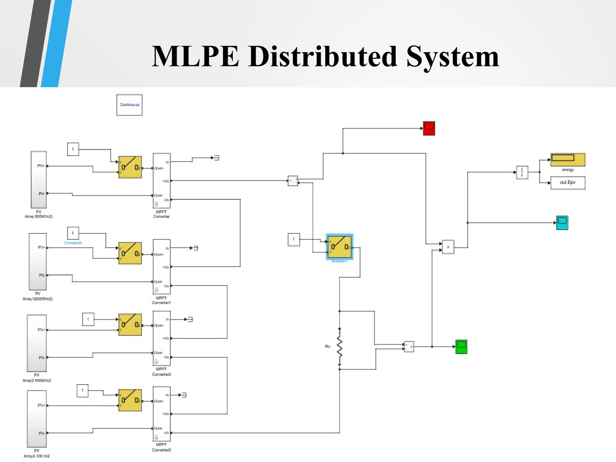
#13 In distributed pv system we use multiple microinverter .
When different centralized pv system are connected together to make distributed pv system
each pv module has its own micro inverter or each system has its own dc to dc converter.
Almost no waste of available PV energy in case of mismatching.
Each module works independently. If one module fails, the other modules will continue to deliver power to the grid.
Low minimum system size. That is, the threshold for people to start their own PV plant is lowered.
Use of standard AC installation material (no DC cabling), which reduces costs of installation material and system design.
No need for string diodes, and therefore no additional conduction losses due to the presence of blocking diodes.
#14 Multiple PV models are reported. There are two commonly used models.
In order to develop a pv model we need to design pv cell.
Single-Diode PV model
Double-Diode PV model
#15 Ideally, a pv cell can be characterized as a current source connected in parallel with a diode. However, a practical model consists of series resistance (Rs) and parallel resistance (Rp).The Rs and Rp represent the practical losses in a PV cell, which is due to leakage current and internal resistance.
The simplicity and accuracy are two trade-offs of this model.
The complete mathematical equation of both models is based on Shockley diode equations.
However, Rs should be very small, almost equal to zero and Rp should be very large, ideally equal to infinity. To simplify the analysis, these resistances may be neglected.
#16 It consists of an extra diode in the equivalent circuit representation to account for space charge losses within the PV cell.
The first diode represents diffusion current element and
the second diode represents space-charge recombination.
#17 With the change of the position of sun, voltage and current chages also changes
if we create a graph between the open circuit voltage and short circuit current graph will be this
If the irradiance and temperature changes continouly mpp also changes
#21 As it is pollution-free, noise-free and limitless source of energy
#23 SMA introduce a software-based power optimizer in a string inverter known as ShadeFix and they claim that their algorithm is more efficient and cost effective compared to other modular level power electronic devices.
Tigo is one of the main leading company of US which is developing MLPE device known as optimizer for 3 major applications i.e., monitoring, optimization, and rapid shutdown. Each optimizer is connected in parallel with solar module.
SolarEdge is the top solar company of USA. There are three common configurations in solar PV system. Centralize PV system, String PV system and Distributive PV system.
Huawei claims are AI based modular level MPPT, fault detection, support different panel orientation, rapid shutdown, smart energy management and monitoring. The communication mechanism used Huawei optimizer is Power Line Communication (PLC). T
the only company which claim microinverter as their product is Enphase.
#27 Traditional techniques
Not able to find Global maximum in case of shading


![[BROCHURE] Italy Tour Project | @SlideON](https://cdn.slidesharecdn.com/ss_thumbnails/brochure8-251215152319-2805af68-thumbnail.jpg?width=640&height=640&fit=bounds)


