System modeling
Systemmodeling is the process of developing abstract
models of a system, with each model presenting a
different view or perspective of that system.
System modeling has now come to mean representing a
system using some kind of graphical notation, which is
now almost always based on notations in the Unified
Modeling Language (UML).
System modelling helps the analyst to understand the
functionality of the system and models are used to
communicate with customers.
Chapter 5 System Modeling 3
4.
Existing and plannedsystem models
Chapter 5 System Modeling 4
Models of the existing system are used during requirements
engineering. They help clarify what the existing system does
and can be used as a basis for discussing its strengths and
weaknesses. These then lead to requirements for the new
system.
Models of the new system are used during requirements
engineering to help explain the proposed requirements to
other system stakeholders. Engineers use these models to
discuss design proposals and to document the system for
implementation.
In a model-driven engineering process, it is possible to
generate a complete or partial system implementation from
the system model.
5.
System perspectives
Chapter 5System Modeling 5
An external perspective, where you model the context
or environment of the system.
An interaction perspective, where you model the
interactions between a system and its environment, or
between the components of a system.
A structural perspective, where you model the
organization of a system or the structure of the data that
is processed by the system.
A behavioral perspective, where you model the d
y
n
a
m
i
c
behavior of the system and how it responds to events.
6.
UML diagram types
Chapter5 System Modeling 6
Activity diagrams, which show the activities involved in a
process or in data processing .
Use case diagrams, which show the interaction
between a system and its environment.
Sequence diagrams, which show interactions between
actors and the system and between system components.
Class diagrams, which show the object classes in t
h
e
system and the associations between these classes.
State diagrams, which show how the system reacts to
internal and external events.
7.
Use of graphicalmodels
Chapter 5 System Modeling 7
As a means of facilitating discussion about an existing or
proposed system
Incomplete and incorrect models are OK as their role is
to support discussion.
As a way of documenting an existing system
Models should be an accurate representation of the system
but need not be complete.
As a detailed system description that can be used to
generate a system implementation
Models have to be both correct and complete.
Context models
Chapter 5System Modeling 9
Context models are used to illustrate the operational
context of a system - they show what lies outside the
system boundaries.
Social and organisational concerns may affect t
h
e
decision on where to position system boundaries.
Architectural models show the system and its
relationship with other systems.
10.
System boundaries
Chapter 5System Modeling 10
System boundaries are established to define what is
inside and what is outside the system.
They show other systems that are used or depend on the
system being developed.
The position of the system boundary has a profound
effect on the system requirements.
Defining a system boundary is a political judgment
There may be pressures to develop system boundaries that
increase / decrease the influence or workload of different parts
of an organization.
11.
The context ofthe Mentcare system
Chapter 5 System Modeling 11
12.
Process perspective
Chapter 5System Modeling 12
Context models simply show the other systems in t
h
e
environment, not how the system being developed is
used in that environment.
Process models reveal how the system being developedis
used in broader business processes.
UML activity diagrams may be used to define business
process models.
13.
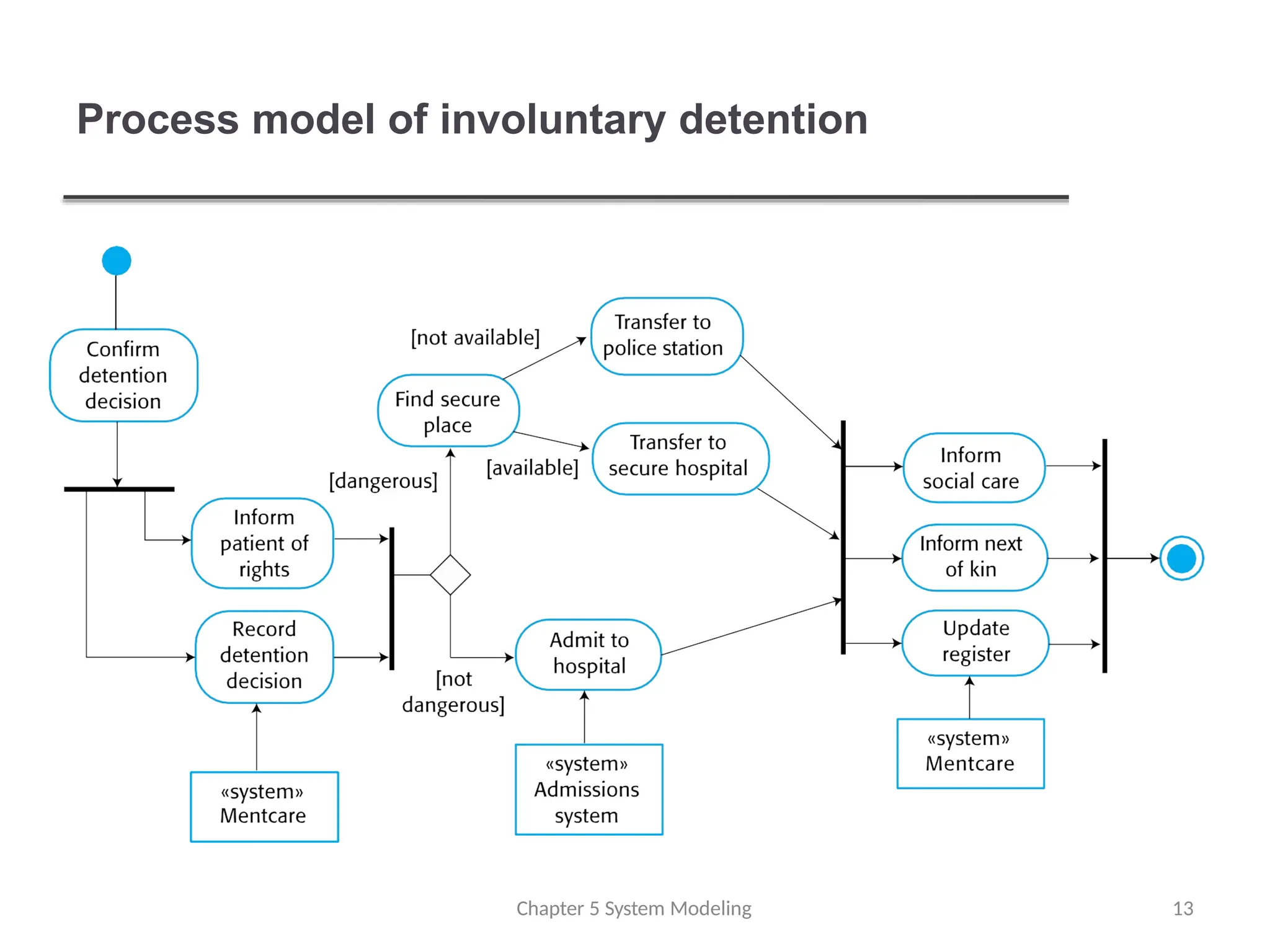
Process model ofinvoluntary detention
Chapter 5 System Modeling 13
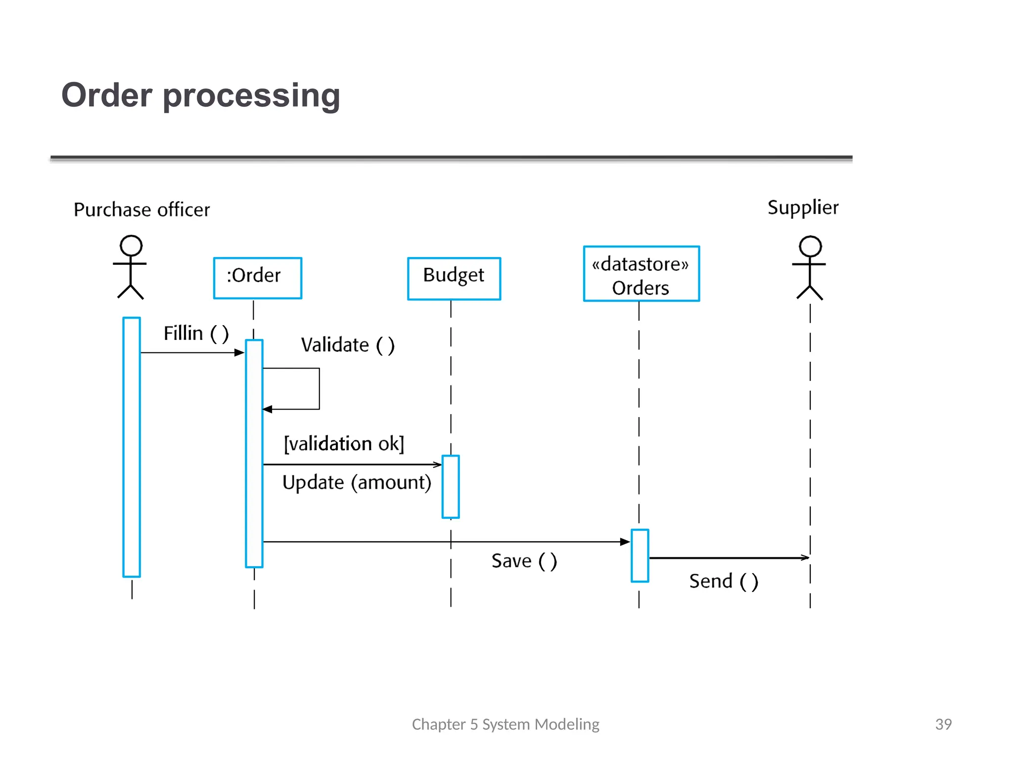
Interaction models
Chapter 5System Modeling 15
Modeling user interaction is important as it helps to
identify user requirements.
Modeling system-to-system interaction highlights
the communication problems that may arise.
Modeling component interaction helps us understand ifa
proposed system structure is likely to deliver the required
system performance and dependability.
Use case diagrams and sequence diagrams may be
used for interaction modeling.
16.
Use case modeling
Use cases were developed originally to support
requirements elicitation and now incorporated into the
UML.
Each use case represents a discrete task that i
n
vo
lv
es
external interaction with a system.
Actors in a use case may be people or other systems.
Represented diagramatically to provide an overview of
the use case and in a more detailed textual form.
Chapter 5 System Modeling 16
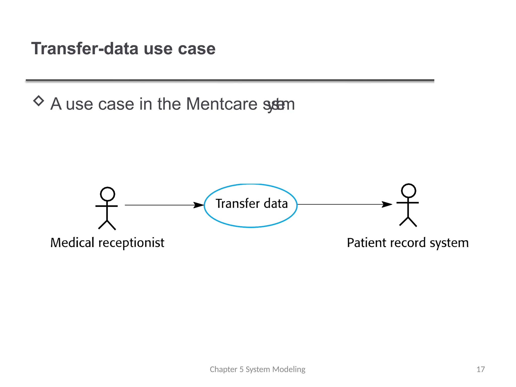
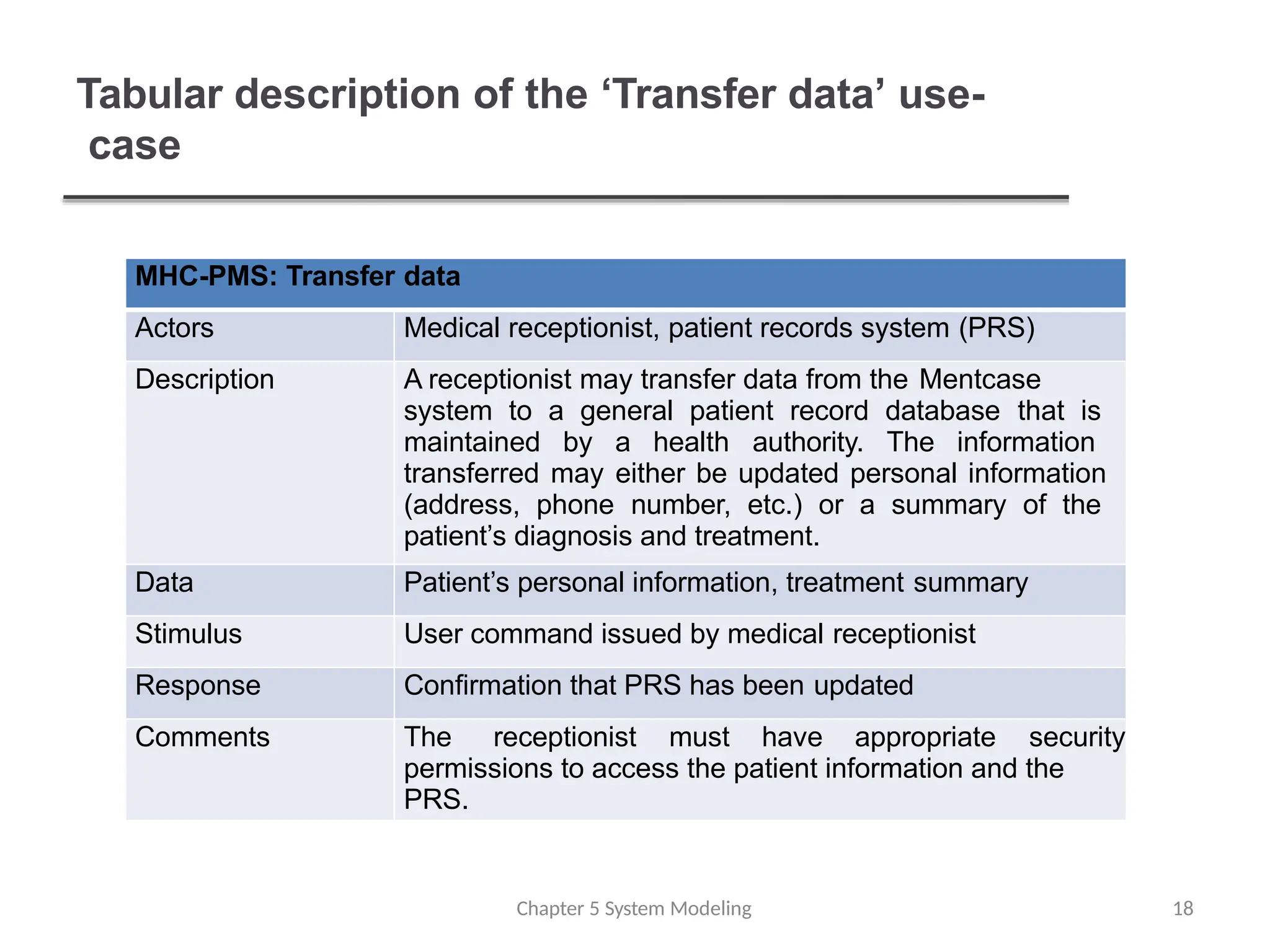
Tabular description ofthe ‘Transfer data’ use-
case
Chapter 5 System Modeling 18
MHC-PMS: Transfer data
Actors Medical receptionist, patient records system (PRS)
Description A receptionist may transfer data from the Mentcase
system to a general patient record database that is
maintained by a health authority. The information
transferred may either be updated personal information
(address, phone number, etc.) or a summary of the
patient’s diagnosis and treatment.
Data Patient’s personal information, treatment summary
Stimulus User command issued by medical receptionist
Response Confirmation that PRS has been updated
Comments The receptionist must have appropriate security
permissions to access the patient information and the
PRS.
19.
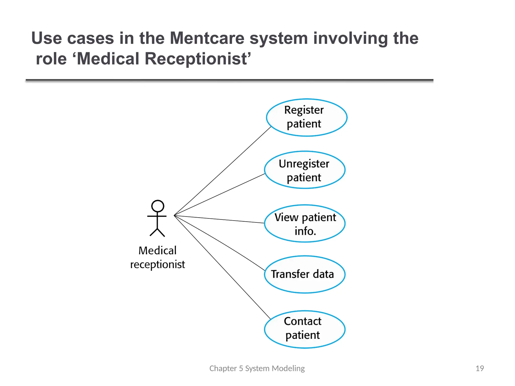
Use cases inthe Mentcare system involving the
role ‘Medical Receptionist’
Chapter 5 System Modeling 19
20.
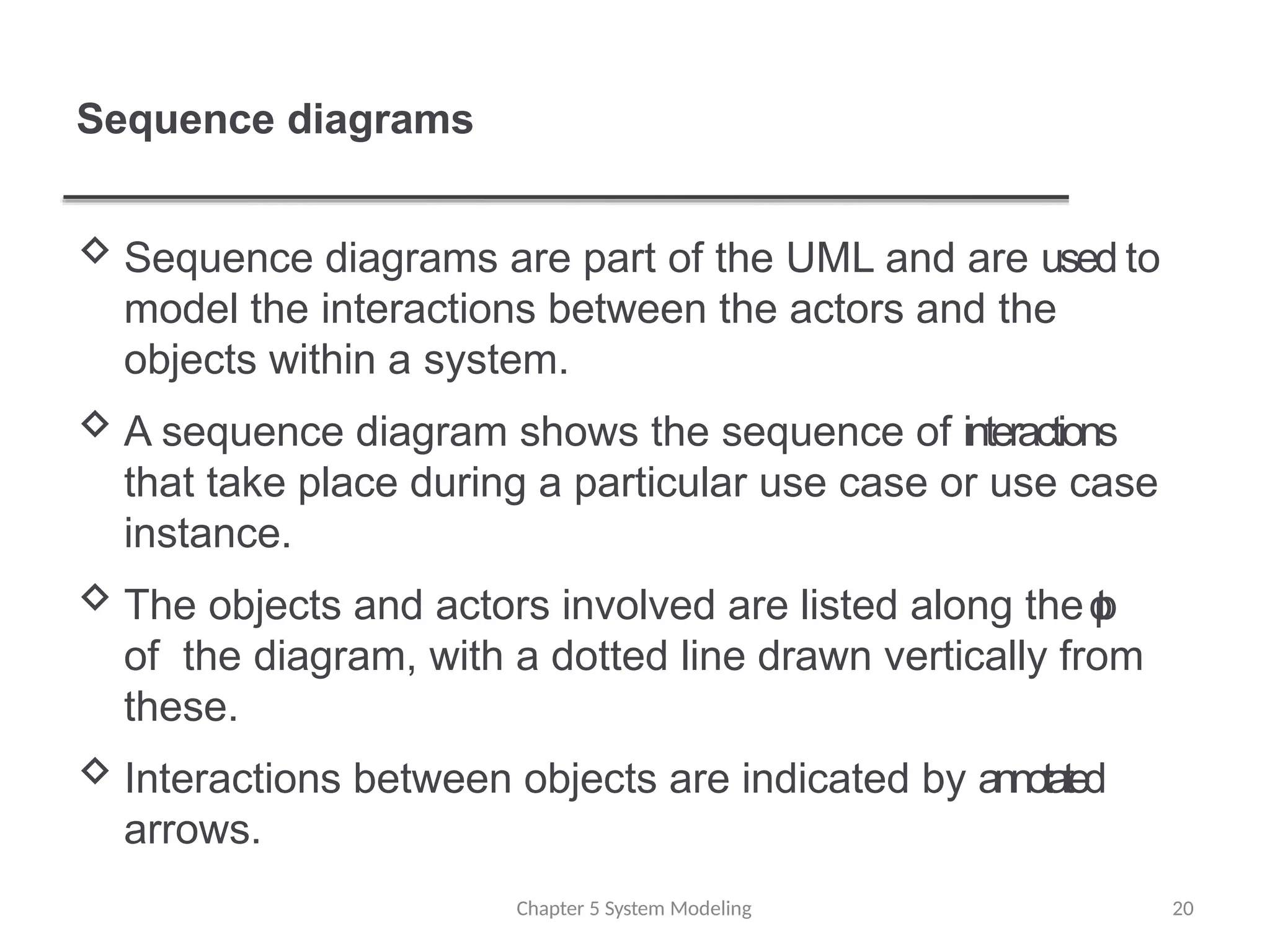
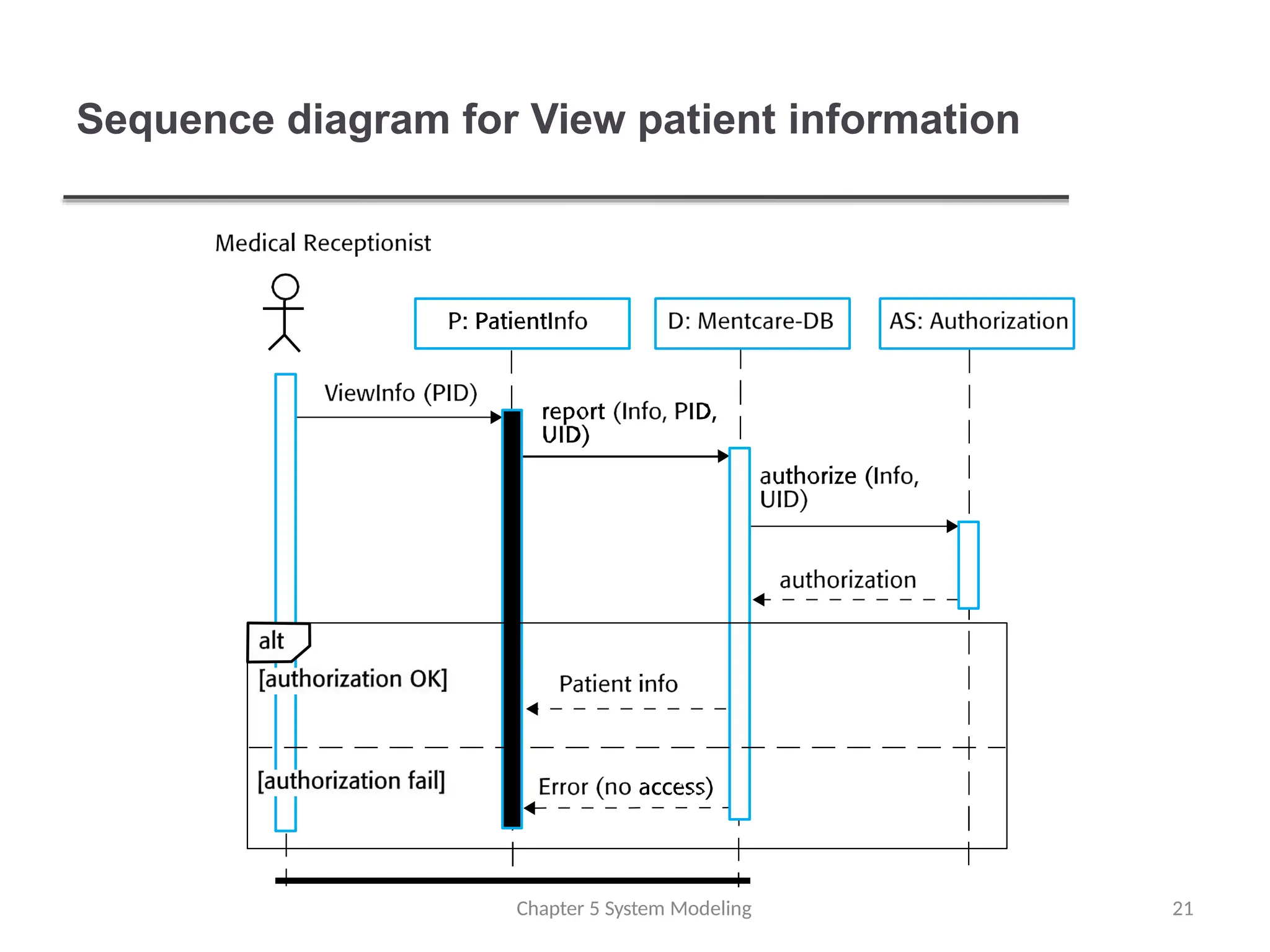
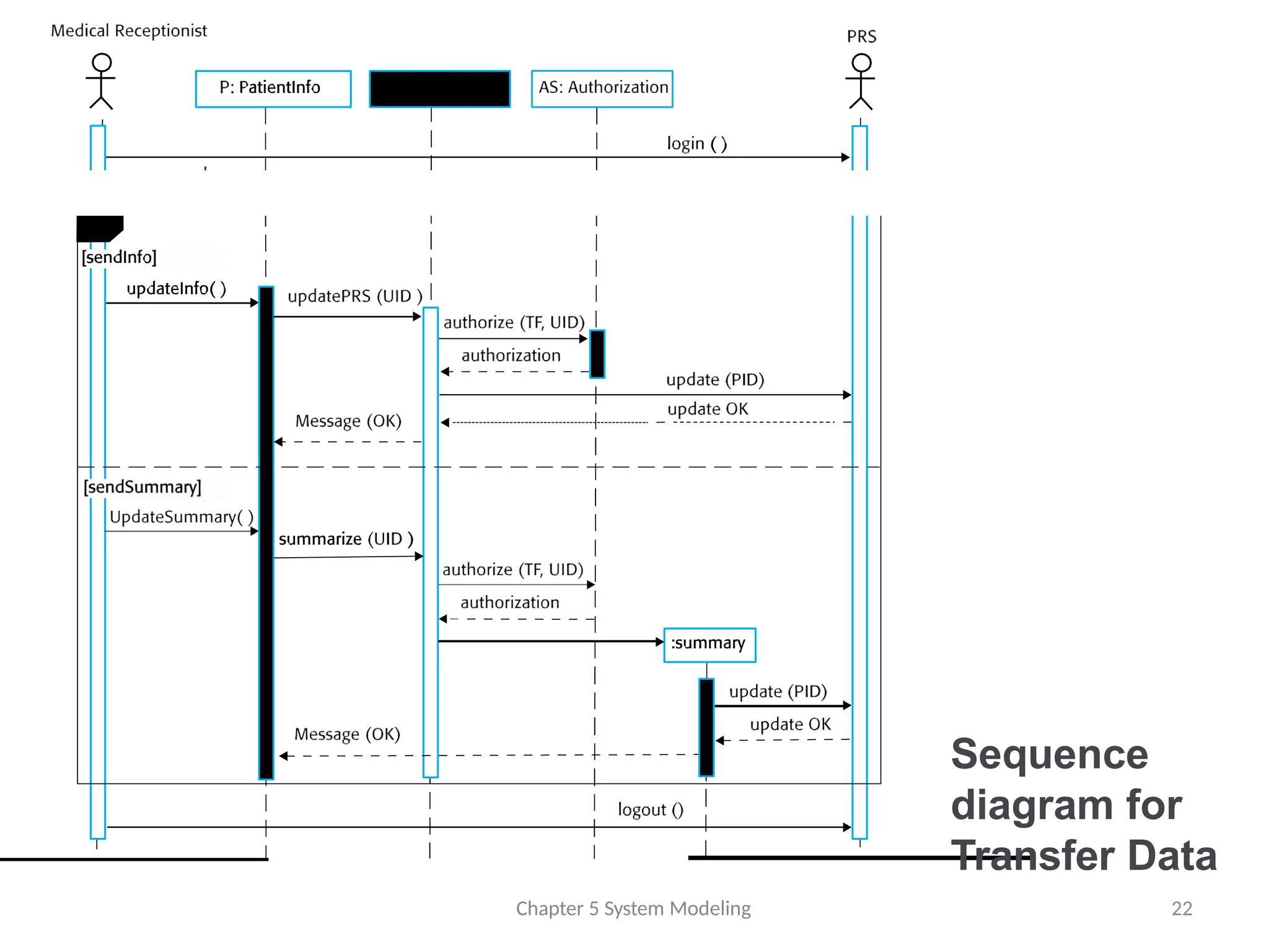
Sequence diagrams
Sequencediagrams are part of the UML and are used to
model the interactions between the actors and the
objects within a system.
A sequence diagram shows the sequence of interactions
that take place during a particular use case or use case
instance.
The objects and actors involved are listed along the t
o
p
of the diagram, with a dotted line drawn vertically from
these.
Interactions between objects are indicated by annotated
arrows.
Chapter 5 System Modeling 20
Structural models
Chapter 5System Modeling 24
Structural models of software display the organization of
a system in terms of the components that make up that
system and their relationships.
Structural models may be static models, which show t
h
e
structure of the system design, or dynamic models,
which show the organization of the system when it is
executing.
You create structural models of a system when you a
r
e
discussing and designing the system architecture.
25.
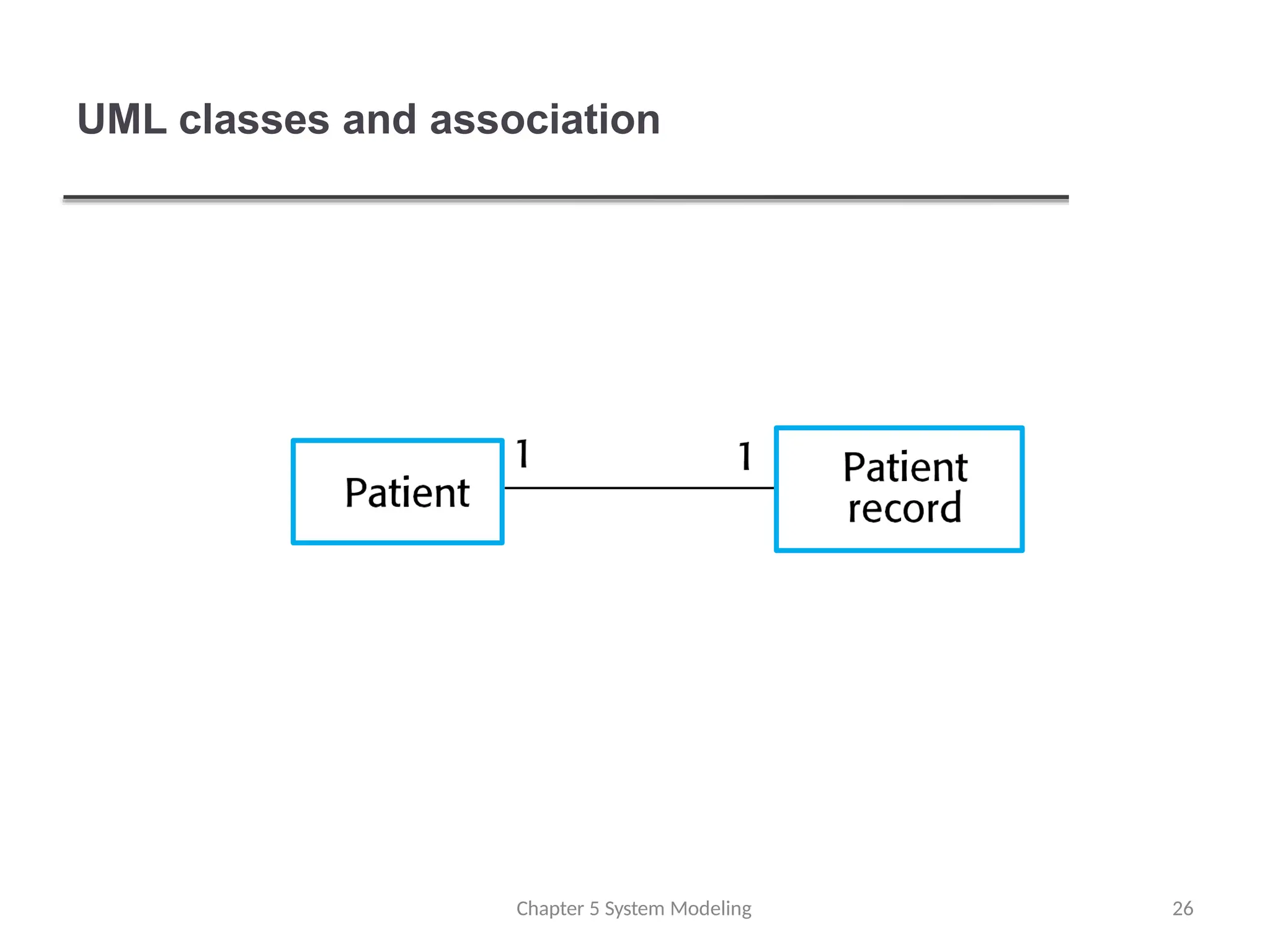
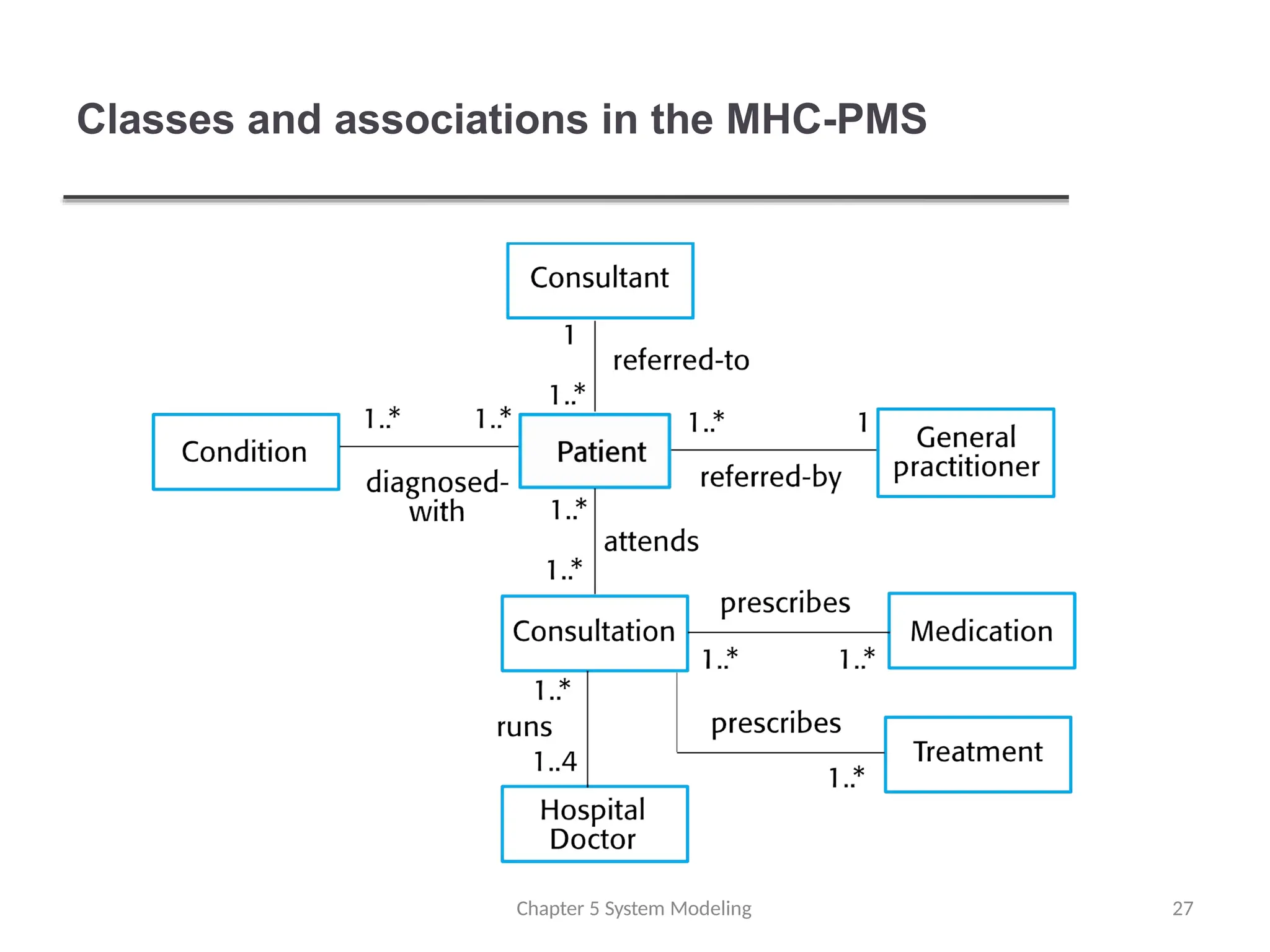
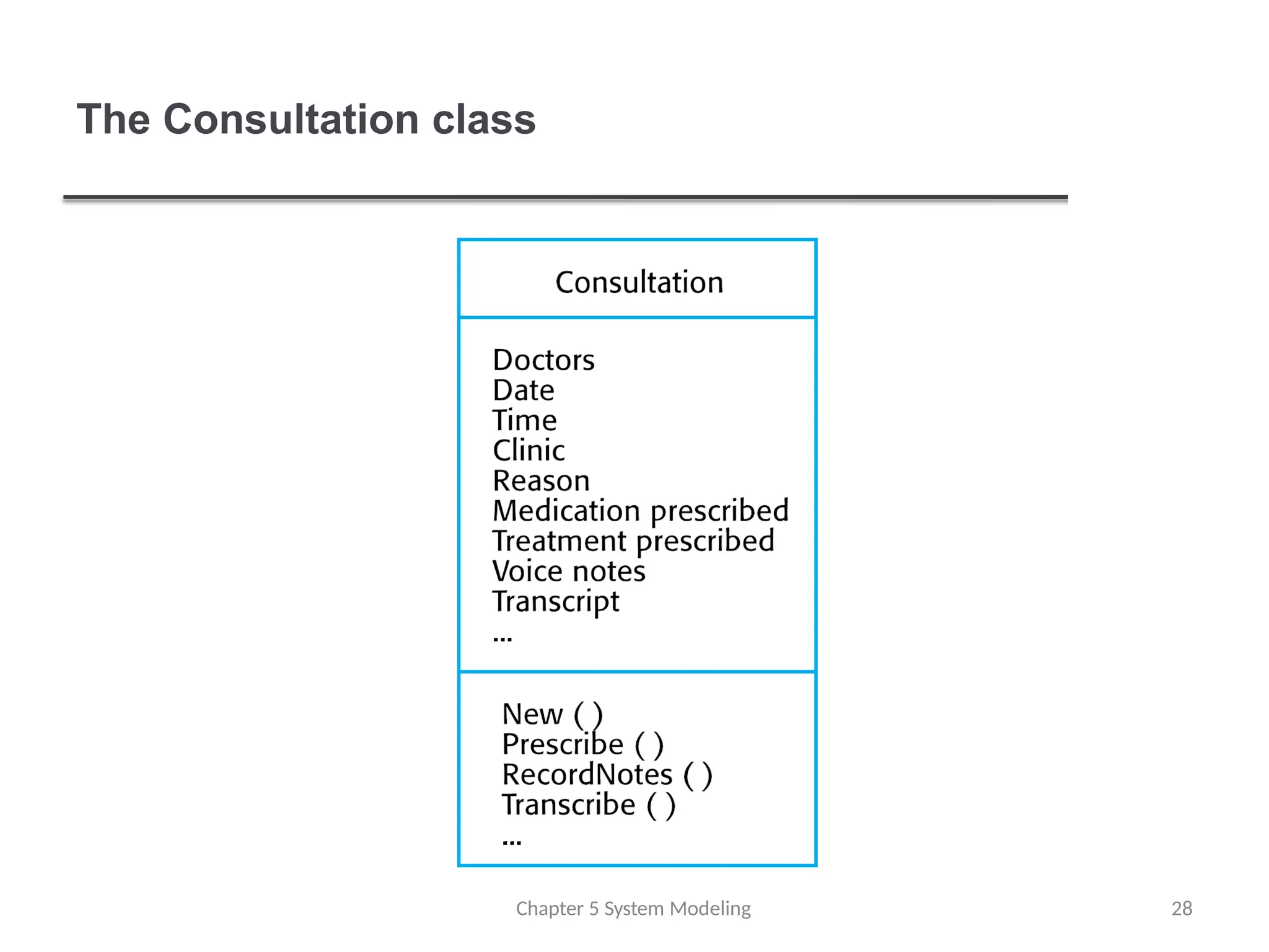
Class diagrams
Classdiagrams are used when developing an object-
oriented system model to show the classes in a system
and the associations between these classes.
An object class can be thought of as a general definitionof
one kind of system object.
An association is a link between classes that indicates
that there is some relationship between these classes.
When you are developing models during the early s
t
a
g
e
sof
the software engineering process, objects represent
something in the real world, such as a patient, a
prescription, doctor, etc.
Chapter 5 System Modeling 25
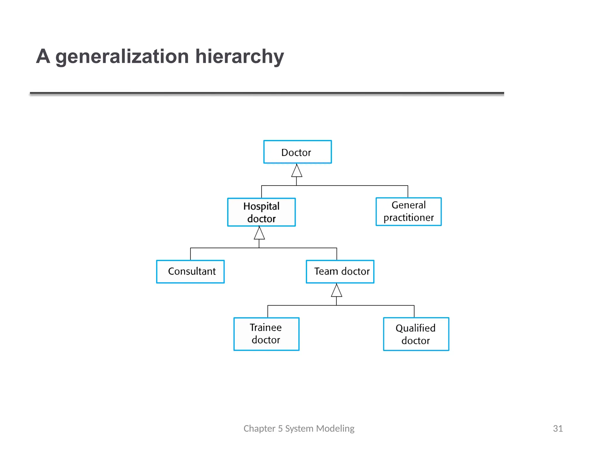
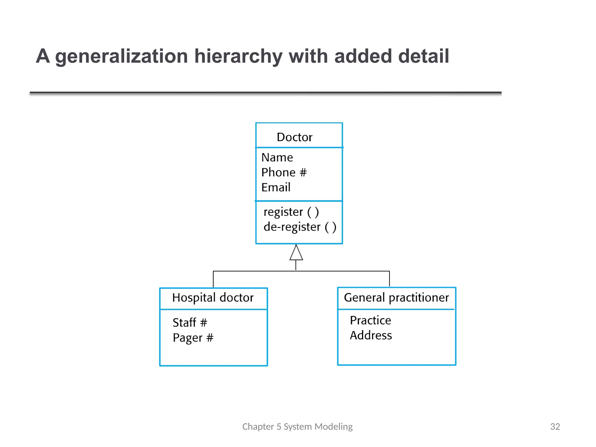
Generalization
Chapter 5 SystemModeling 29
Generalization is an everyday technique that we use to
manage complexity.
Rather than learn the detailed characteristics of e
v
e
ry
entity that we experience, we place these entities in
more general classes (animals, cars, houses, etc.) and
learn the characteristics of these classes.
This allows us to infer that different members of t
h
e
s
e
classes have some common characteristics e.g.
squirrels and rats are rodents.
30.
Generalization
Chapter 5 SystemModeling 30
In modeling systems, it is often useful to examine the classes in
a system to see if there is scope for generalization. If changes
are proposed, then you do not have to look at all classes in the
system to see if they are affected by the change.
In object-oriented languages, such as Java, generalization i
s
implemented using the class inheritance mechanisms built into
the language.
In a generalization, the attributes and operations associated w
i
t
h
higher-level classes are also associated with the lower-level
classes.
The lower-level classes are subclasses inherit the attributes
and operations from their superclasses. These lower-level
classes then add more specific attributes and operations.
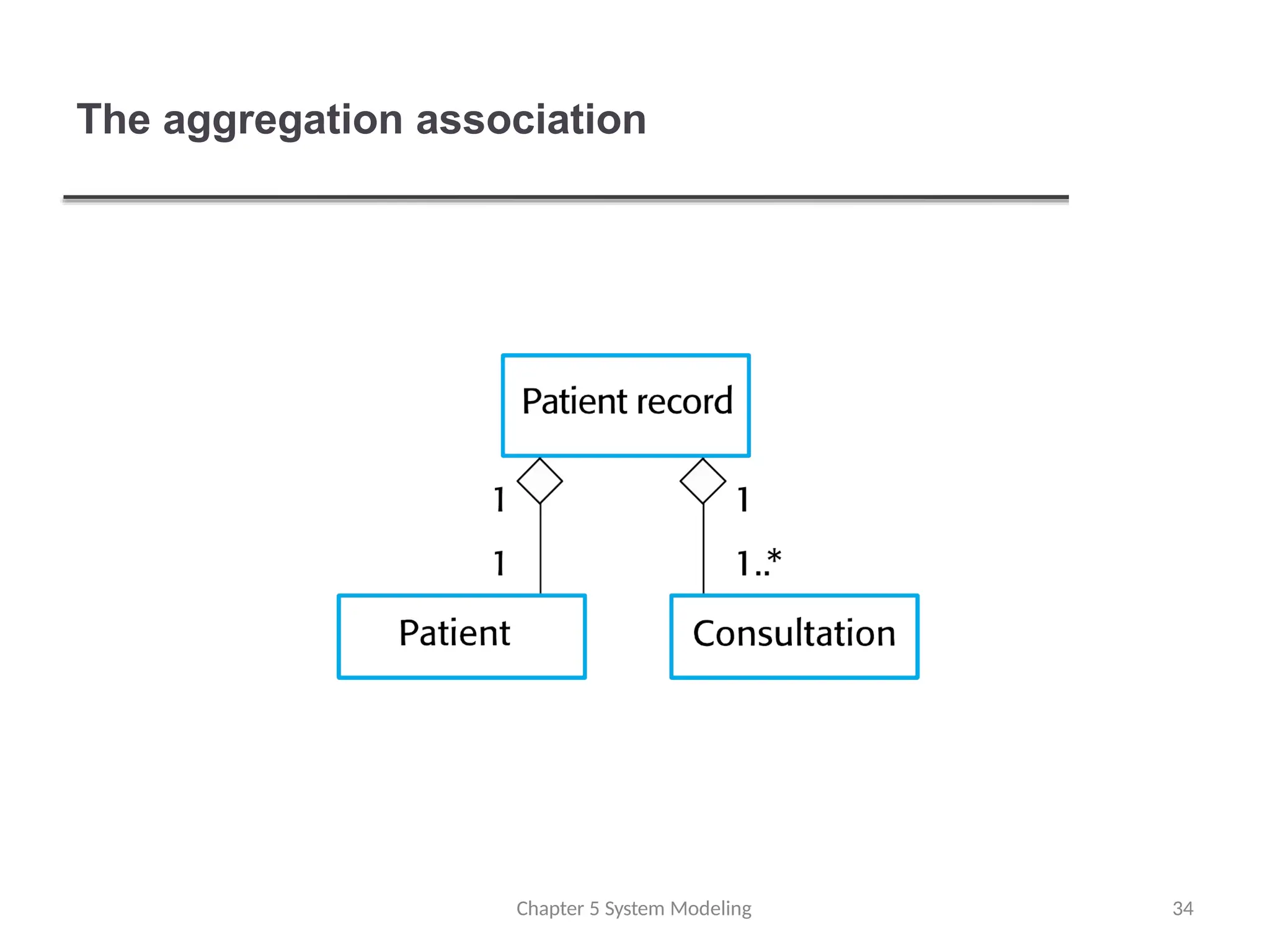
Object class aggregationmodels
An aggregation model shows how classes that a
r
e
collections are composed of other classes.
Aggregation models are similar to the part-of relationshipin
semantic data models.
Chapter 5 System Modeling 33
Behavioral models
Chapter 5System Modeling 36
Behavioral models are models of the dynamic behavior of
a system as it is executing. They show what happens or
what is supposed to happen when a system responds to
a stimulus from its environment.
You can think of these stimuli as being of two types:
Data Some data arrives that has to be processed by the
system.
Events Some event happens that triggers system
processing. Events may have associated data, although this
is not always the case.
37.
Data-driven modeling
Manybusiness systems are data-processing systems
that are primarily driven by data. They are controlled by
the data input to the system, with relatively little external
event processing.
Data-driven models show the sequence of actions
involved in processing input data and generating an
associated output.
They are particularly useful during the analysis of
requirements as they can be used to show end-to-end
processing in a system.
Chapter 5 System Modeling 37
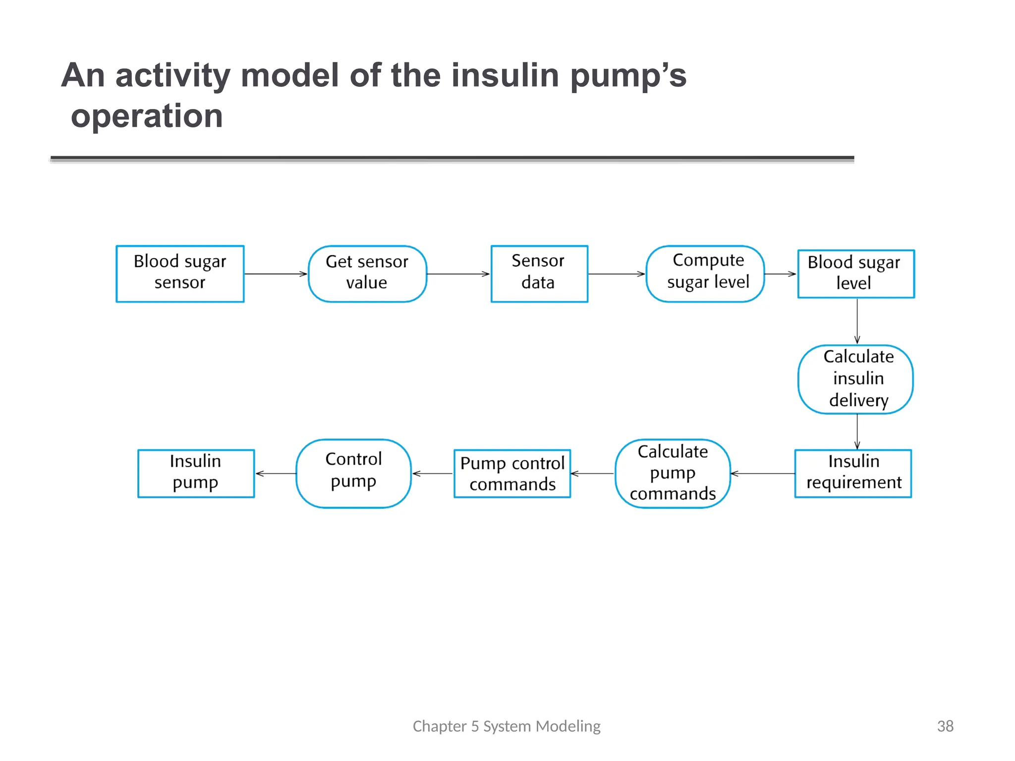
38.
An activity modelof the insulin pump’s
operation
Chapter 5 System Modeling 38
Event-driven modeling
Chapter 5System Modeling 40
Real-time systems are often event-driven, with minimal
data processing. For example, a landline phone
switching system responds to events such as ‘receiver
off hook’ by generating a dial tone.
Event-driven modeling shows how a system responds
to
external and internal events.
It is based on the assumption that a system has a f
i
n
i
t
e
number of states and that events (stimuli) may cause a
transition from one state to another.
41.
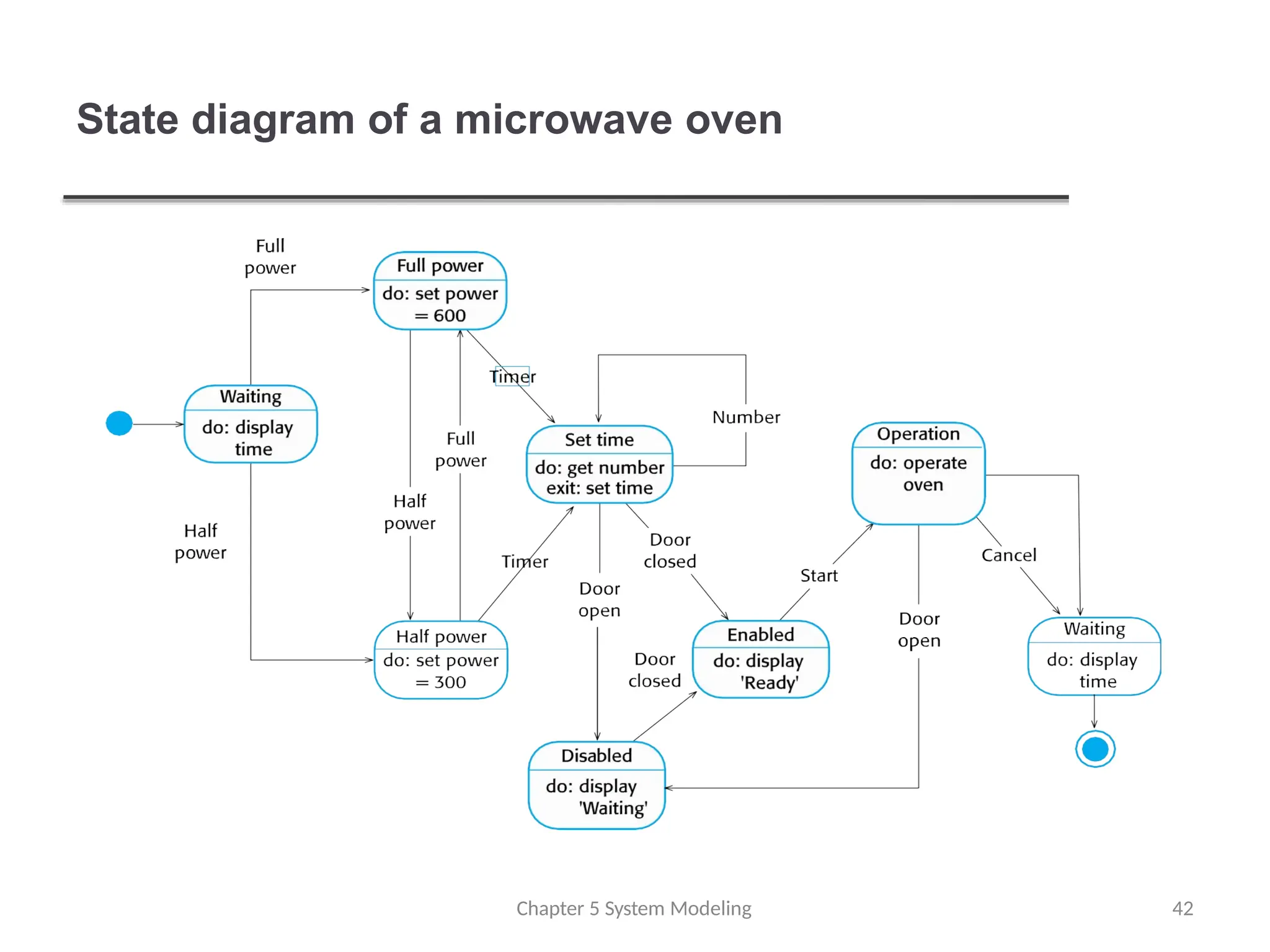
State machine models
Chapter5 System Modeling 41
These model the behaviour of the system in response to
external and internal events.
They show the system’s responses to stimuli so a
r
e
often used for modelling real-time systems.
State machine models show system states as nodes a
n
d
events as arcs between these nodes. When an event
occurs, the system moves from one state to another.
Statecharts are an integral part of the UML and are u
s
e
d
to represent state machine models.
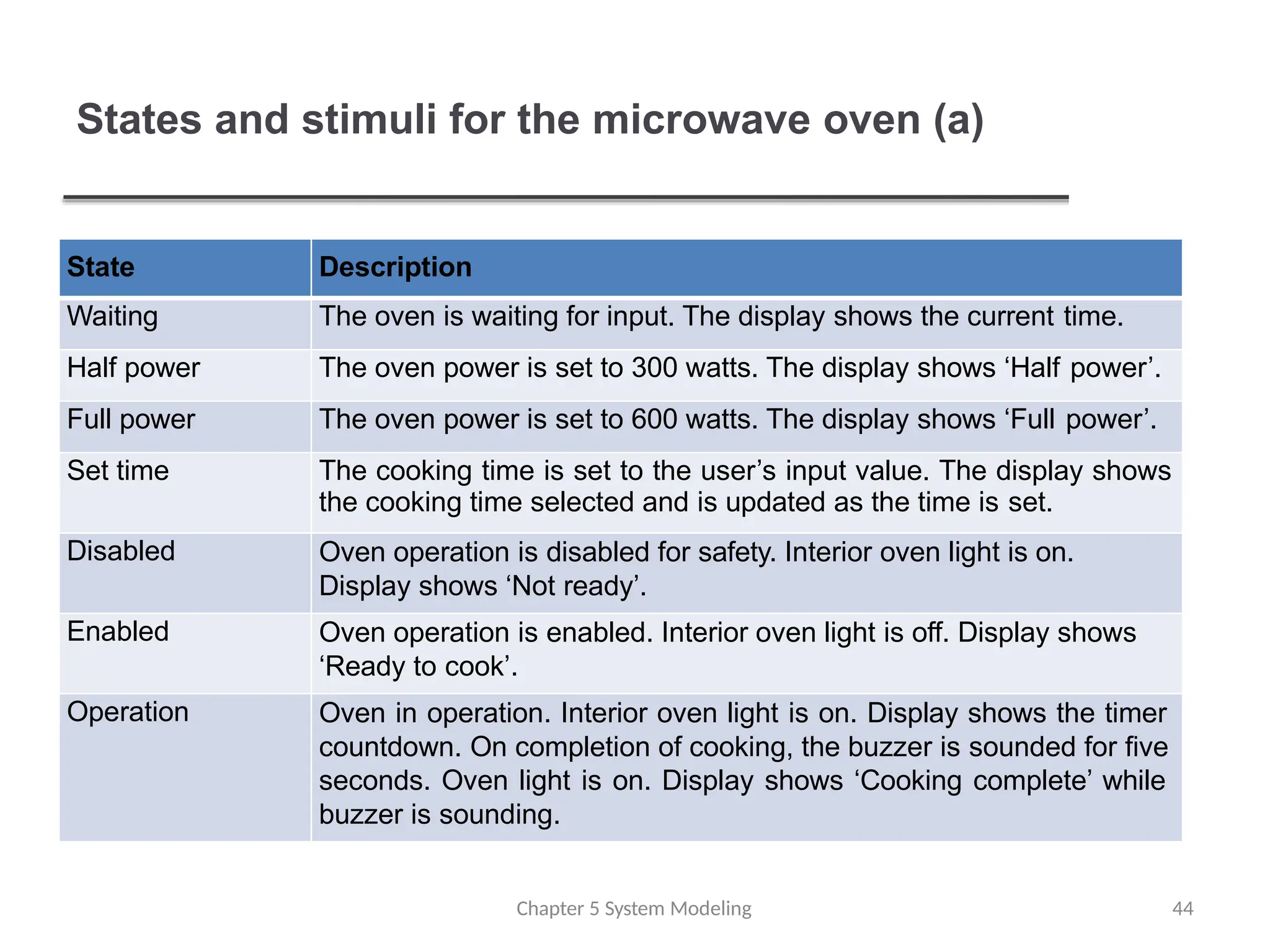
States and stimulifor the microwave oven (a)
Chapter 5 System Modeling 44
State Description
Waiting The oven is waiting for input. The display shows the current time.
Half power The oven power is set to 300 watts. The display shows ‘Half power’.
Full power The oven power is set to 600 watts. The display shows ‘Full power’.
Set time The cooking time is set to the user’s input value. The display shows
the cooking time selected and is updated as the time is set.
Disabled Oven operation is disabled for safety. Interior oven light is on.
Display shows ‘Not ready’.
Enabled Oven operation is enabled. Interior oven light is off. Display shows
‘Ready to cook’.
Operation Oven in operation. Interior oven light is on. Display shows the timer
countdown. On completion of cooking, the buzzer is sounded for five
seconds. Oven light is on. Display shows ‘Cooking complete’ while
buzzer is sounding.
45.
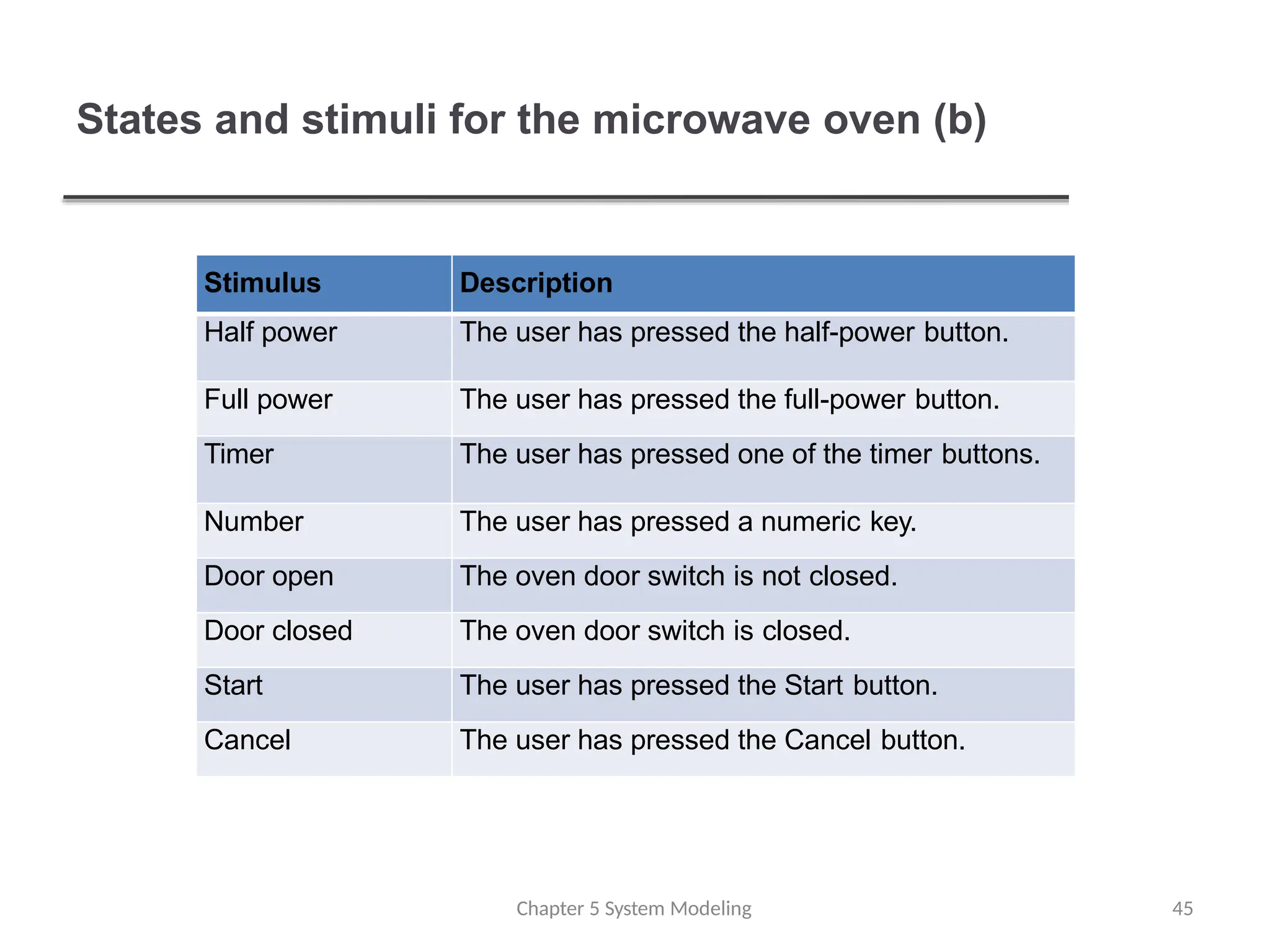
States and stimulifor the microwave oven (b)
Chapter 5 System Modeling 45
Stimulus Description
Half power The user has pressed the half-power button.
Full power The user has pressed the full-power button.
Timer The user has pressed one of the timer buttons.
Number The user has pressed a numeric key.
Door open The oven door switch is not closed.
Door closed The oven door switch is closed.
Start The user has pressed the Start button.
Cancel The user has pressed the Cancel button.
Model-driven engineering
Chapter 5System Modeling 47
Model-driven engineering (MDE) is an approach to
software development where models rather than
programs are the principal outputs of the development
process.
The programs that execute on a hardware/software
platform are then generated automatically from the
models.
Proponents of MDE argue that this raises the level of
abstraction in software engineering so that engineers no
longer have to be concerned with programming
language details or the specifics of execution platforms.
48.
Usage of model-drivenengineering
Chapter 5 System Modeling 48
Model-driven engineering is still at an early stage of
development, and it is unclear whether or not it will have
a significant effect on software engineering practice.
Pros
Allows systems to be considered at higher levels of abstraction
Generating code automatically means that it is cheaper to
adapt systems to new platforms.
Cons
Models for abstraction and not necessarily right
for implementation.
Savings from generating code may be outweighed by the
costs of developing translators for new platforms.
49.
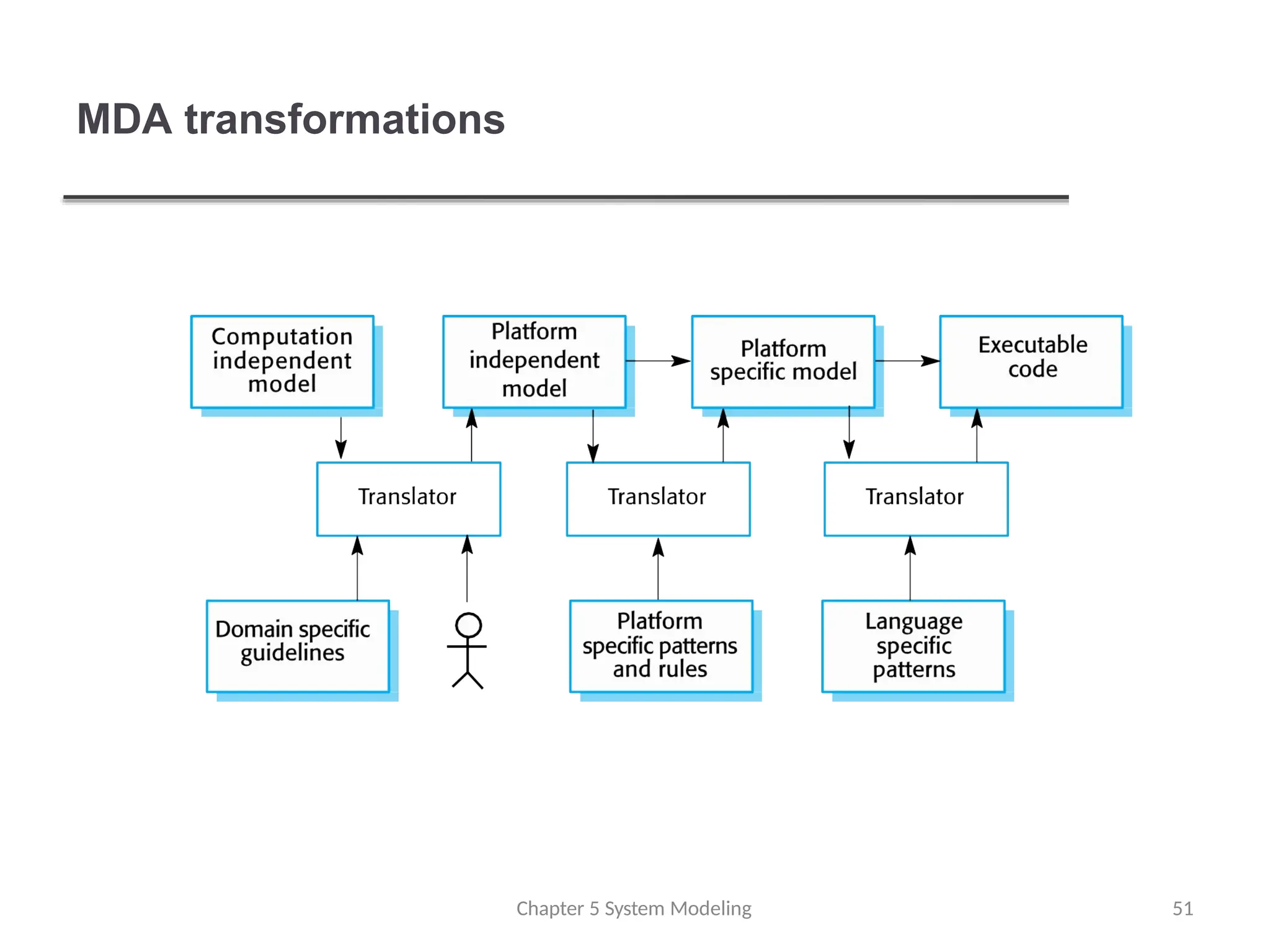
Model driven architecture
Chapter5 System Modeling 49
Model-driven architecture (MDA) was the precursor of
more general model-driven engineering
MDA is a model-focused approach to software design
and implementation that uses a subset of UML models to
describe a system.
Models at different levels of abstraction are created.
From a high-level, platform independent model, it is
possible, in principle, to generate a working program
without manual intervention.
50.
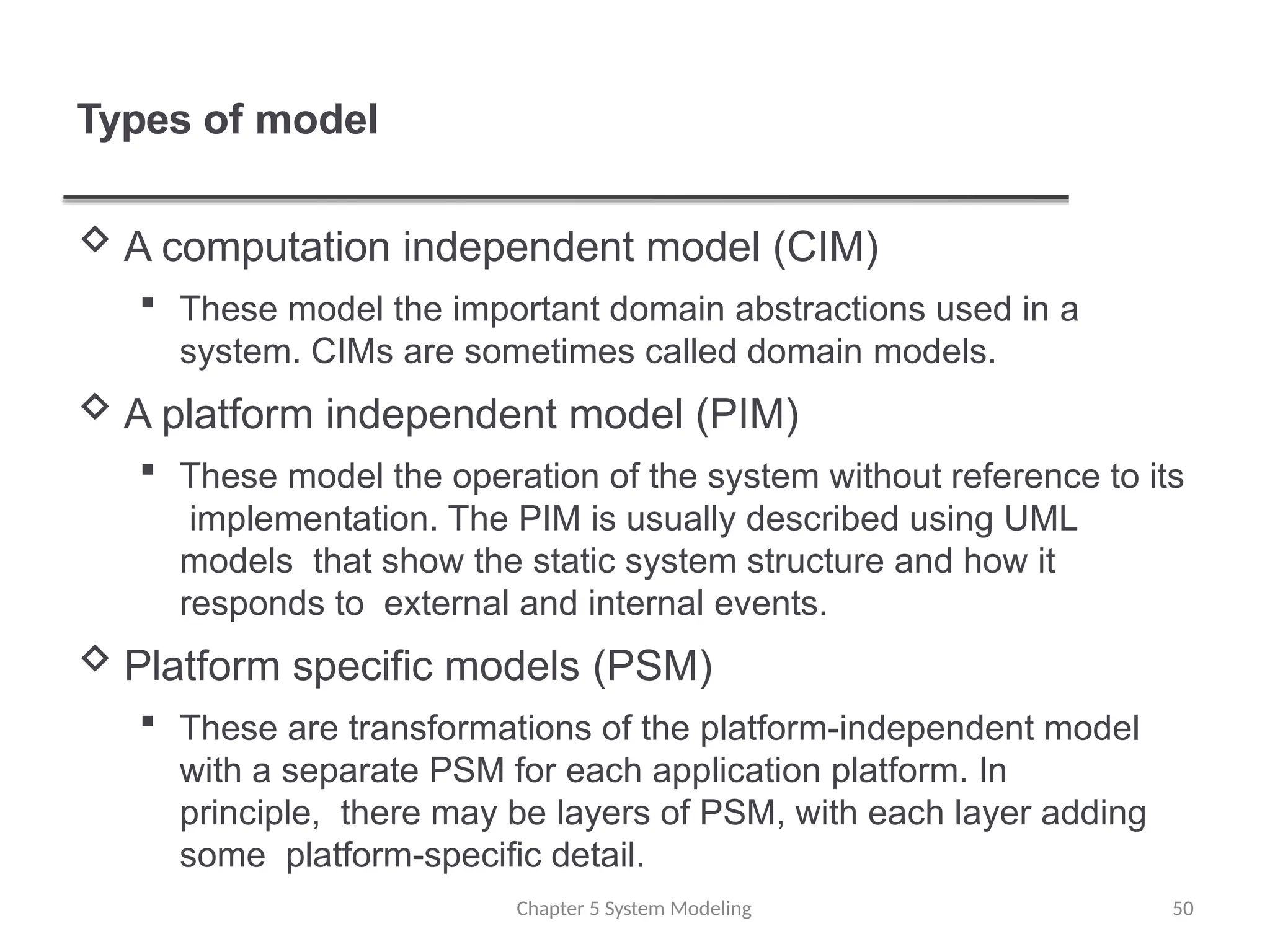
Types of model
Chapter5 System Modeling 50
A computation independent model (CIM)
These model the important domain abstractions used in a
system. CIMs are sometimes called domain models.
A platform independent model (PIM)
These model the operation of the system without reference to its
implementation. The PIM is usually described using UML
models that show the static system structure and how it
responds to external and internal events.
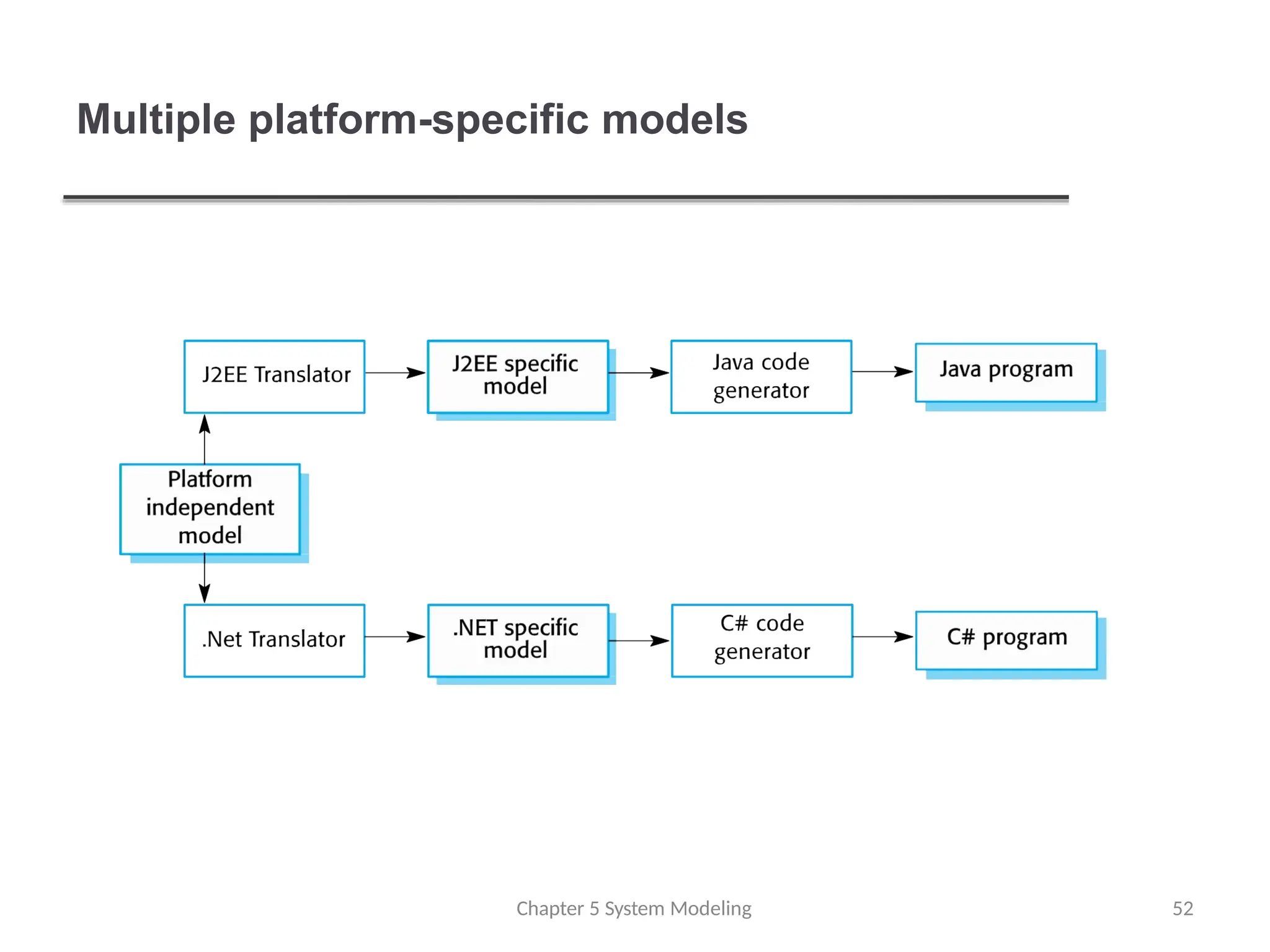
Platform specific models (PSM)
These are transformations of the platform-independent model
with a separate PSM for each application platform. In
principle, there may be layers of PSM, with each layer adding
some platform-specific detail.
Agile methods andMDA
The developers of MDA claim that it is intended to
support an iterative approach to development and so can
be used within agile methods.
The notion of extensive up-front modeling contradicts t
h
e
fundamental ideas in the agile manifesto and I suspect
that few agile developers feel comfortable with model-
driven engineering.
If transformations can be completely automated a
n
da
complete program generated from a PIM, then, in
principle, MDA could be used in an agile development
process as no separate coding would be required.
Chapter 5 System Modeling 53
54.
Adoption of MDA
A range of factors has limited the adoption of M
D
E
/
M
D
A
Specialized tool support is required to convert m
o
d
e
l
s
from one level to another
There is limited tool availability and organizations m
a
y
require tool adaptation and customisation to their
environment
For the long-lifetime systems developed using M
D
A
,
companies are reluctant to develop their own tools or
rely on small companies that may go out of business
Chapter 5 System Modeling 54
55.
Adoption of MDA
Models are a good way of facilitating discussions abouta
software design. Howeverthe abstractions that are useful
for discussions may not be the right abstractions for
implementation.
For most complex systems, implementation is not the
major problem – requirements engineering, security and
dependability, integration with legacy systems and
testing are all more significant.
Chapter 5 System Modeling 55
56.
Adoption of MDA
The arguments for platform-independence are only v
a
l
i
dfor
large, long-lifetime systems. For software products and
information systems, the savings from the use of MDA
are likely to be outweighed by the costs of its
introduction and tooling.
The widespread adoption of agile methods over t
h
e
same period that MDA was evolving has diverted
attention away from model-driven approaches.
Chapter 5 System Modeling 56
57.
Key points
Chapter 5System Modeling 57
A model is an abstract view of a system that ignores system details.
Complementary system models can be developed to show the
system’s context, interactions, structure and behavior.
Context models show how a system that is being modeled is
positioned in an environment with other systems and
processes.
Use case diagrams and sequence diagrams are used to describe
the interactions between users and systems in the system being
designed. Use cases describe interactions between a system and
external actors; sequence diagrams add more information to
these by showing interactions between system objects.
Structural models show the organization and architecture of a
system. Class diagrams are used to define the static structure
of classes in a system and their associations.
58.
Key points
Chapter 5System Modeling 58
Behavioral models are used to describe the dynamic behaviorof
an executing system. This behavior can be modeled from the
perspective of the data processed by the system, or by the
events that stimulate responses from a system.
Activity diagrams may be used to model the processing of
data, where each activity represents one process step.
State diagrams are used to model a system’s behavior in
response to internal or external events.
Model-driven engineering is an approach to software
development in which a system is represented as a set of
models that can be automatically transformed to executable
code.
Editor's Notes
#36 The system must produce a response within a specified time. For example a temperature sensor may be polled 10 times per second.