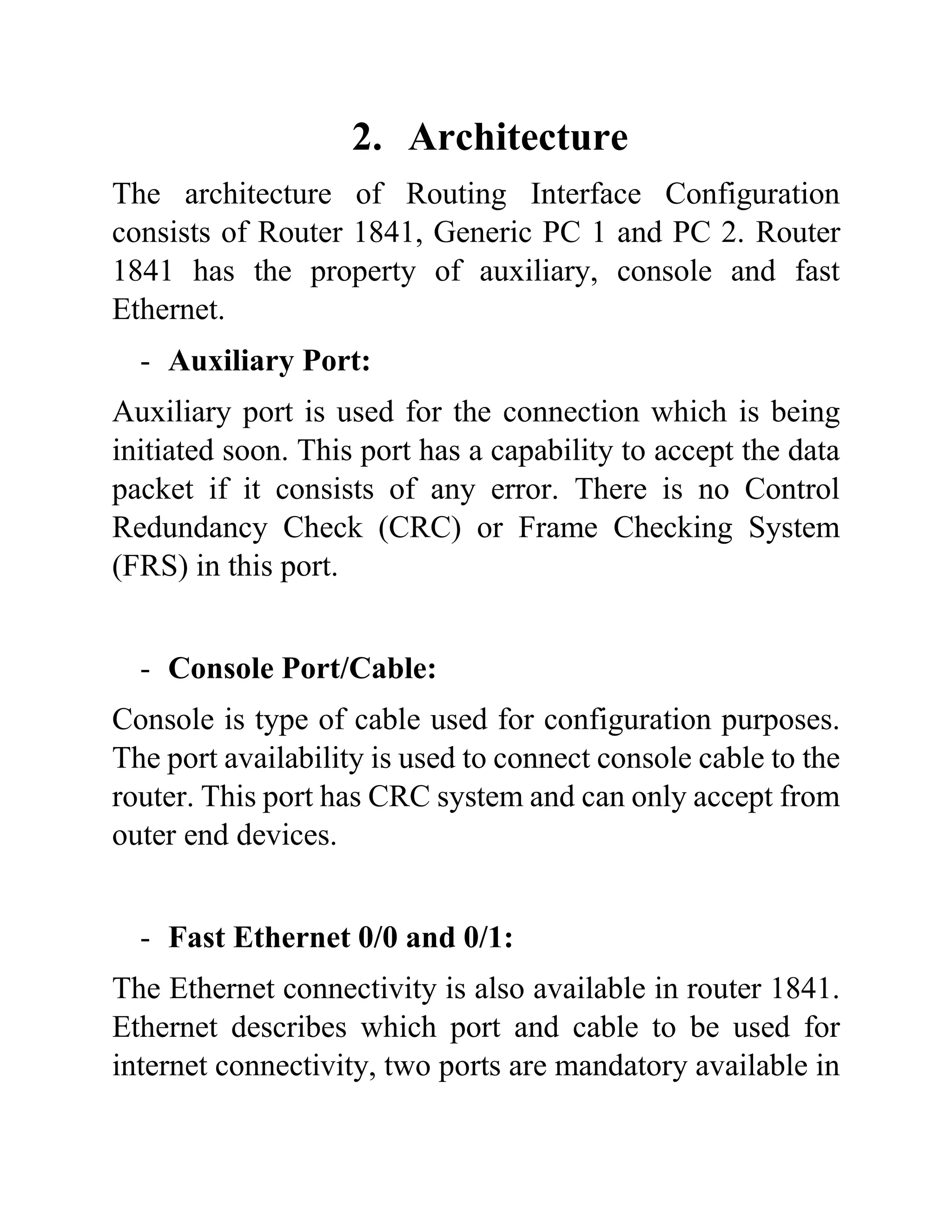
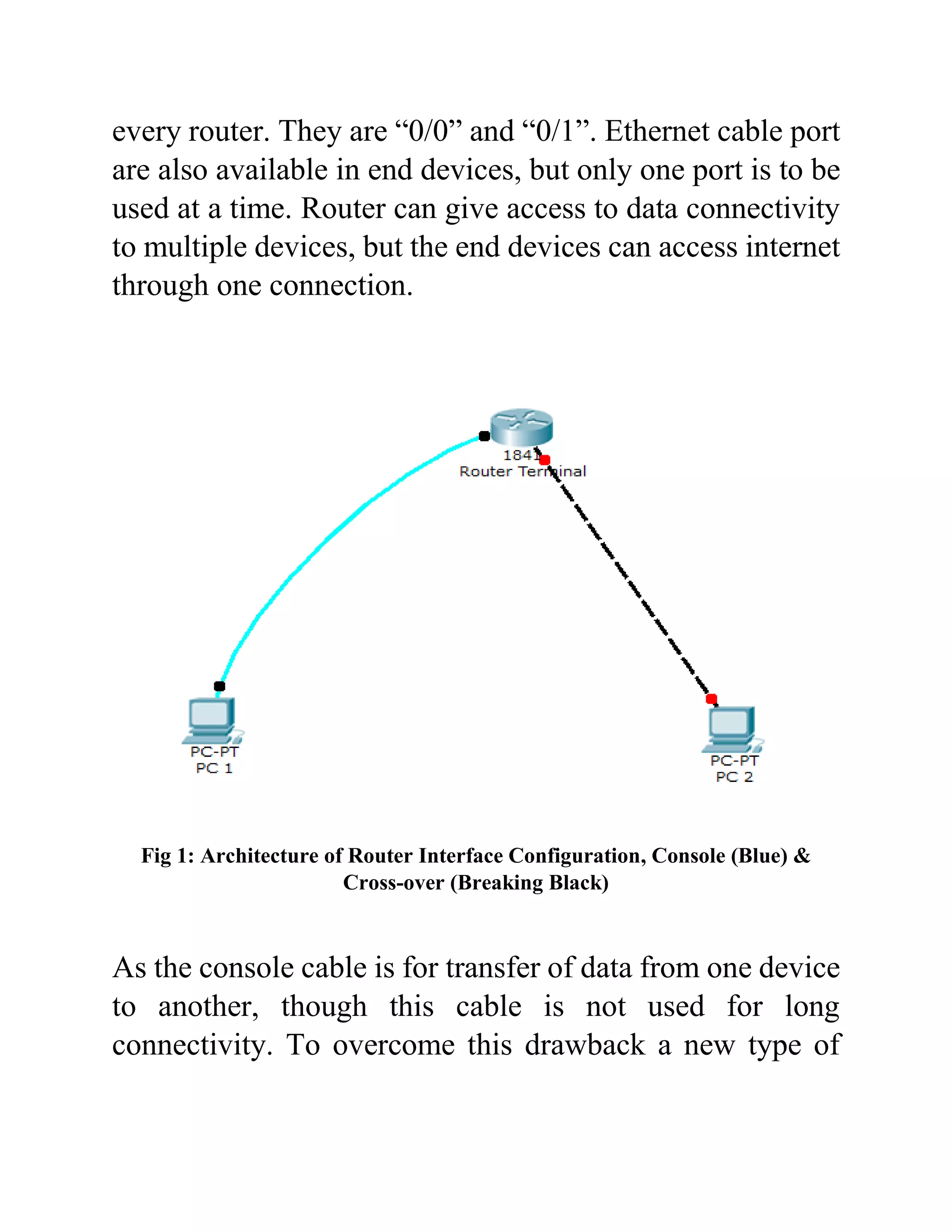
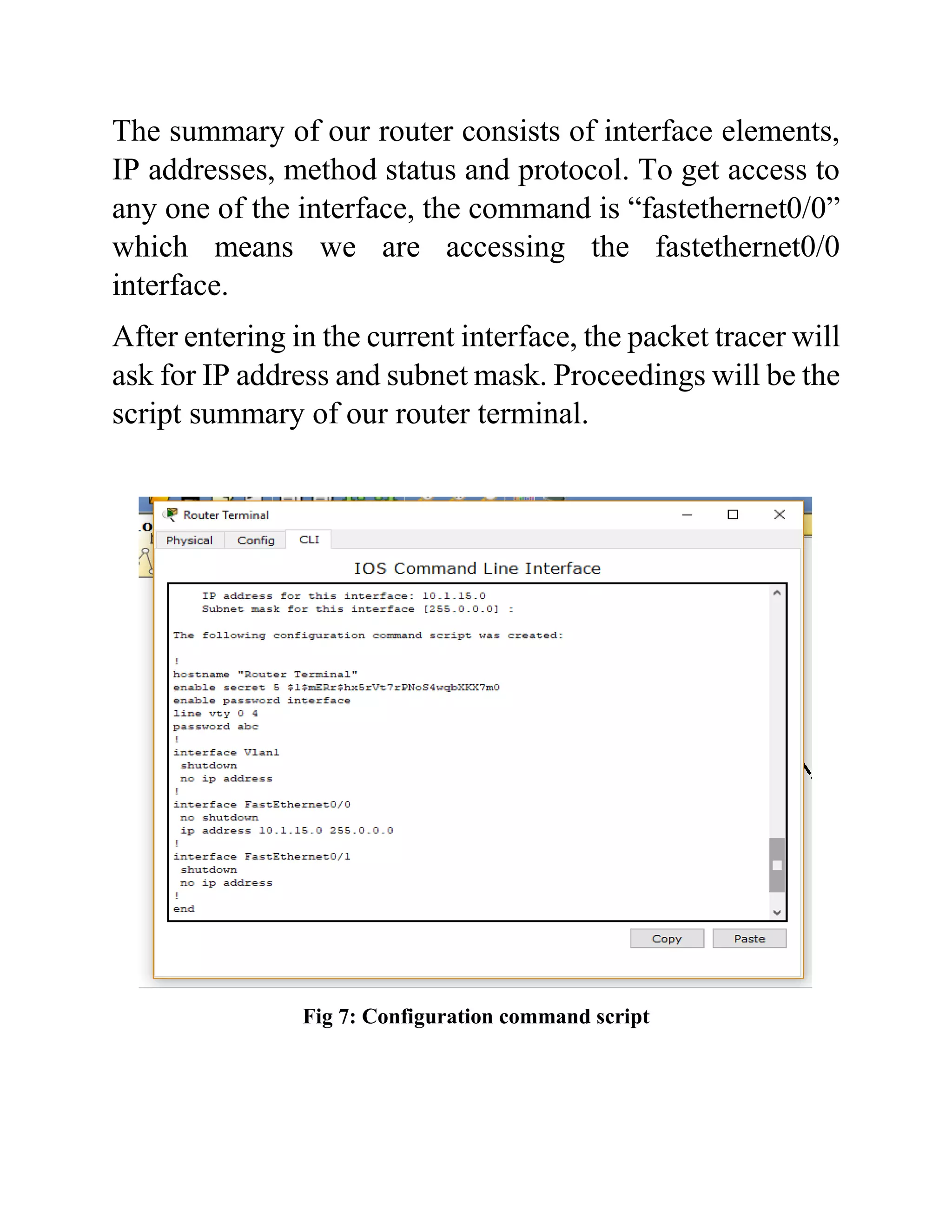
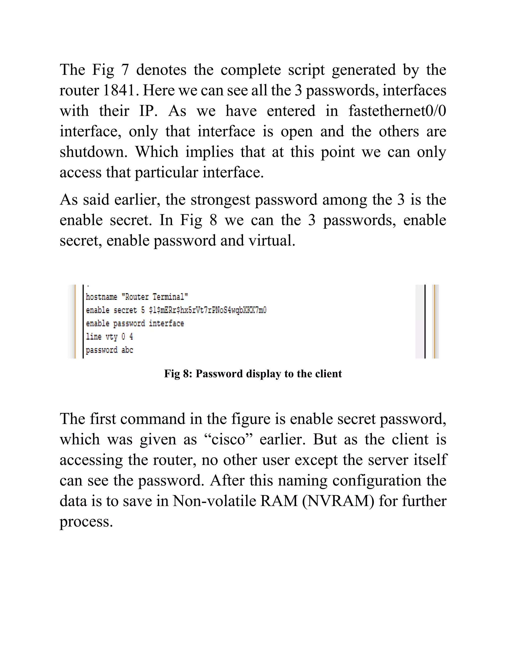
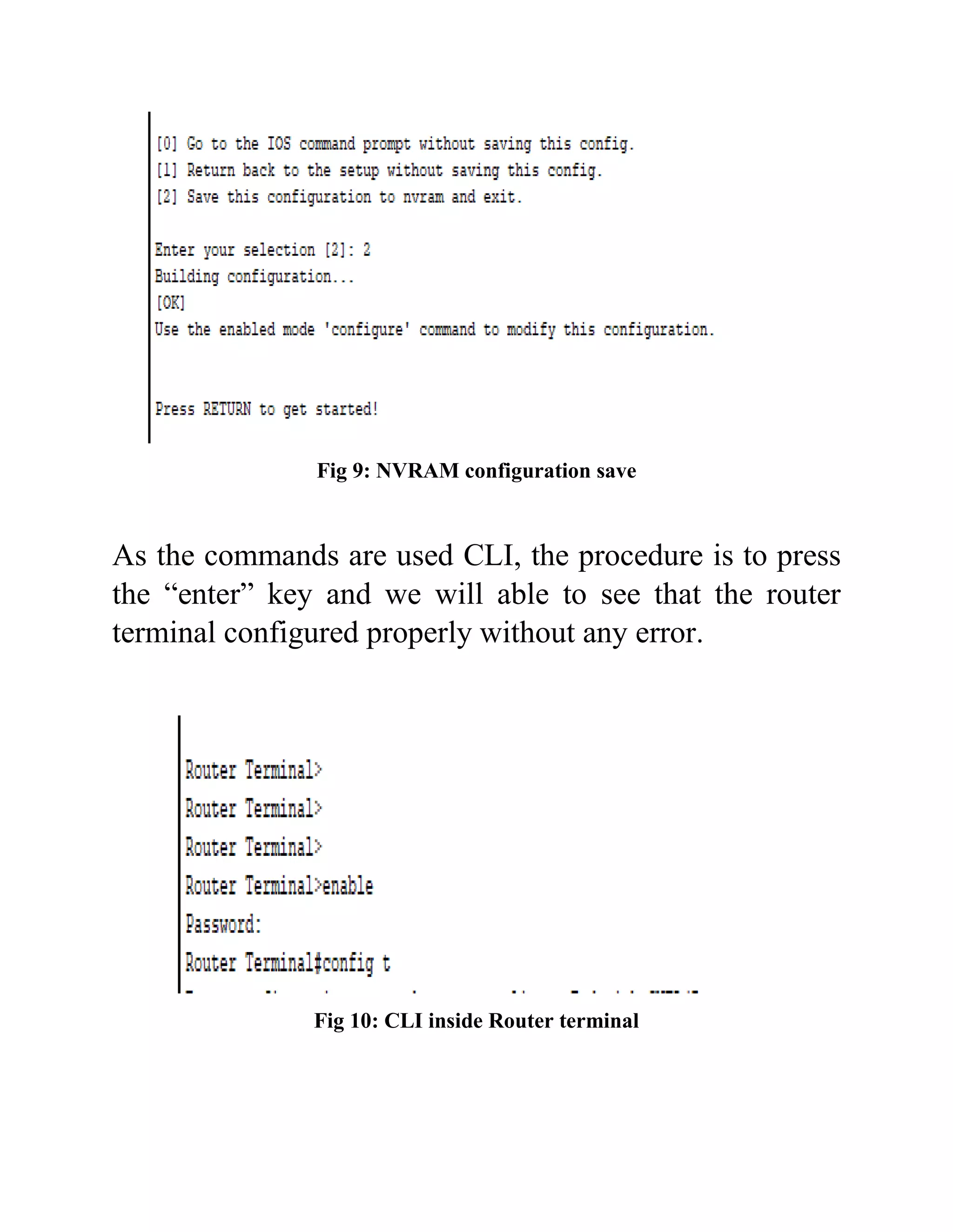
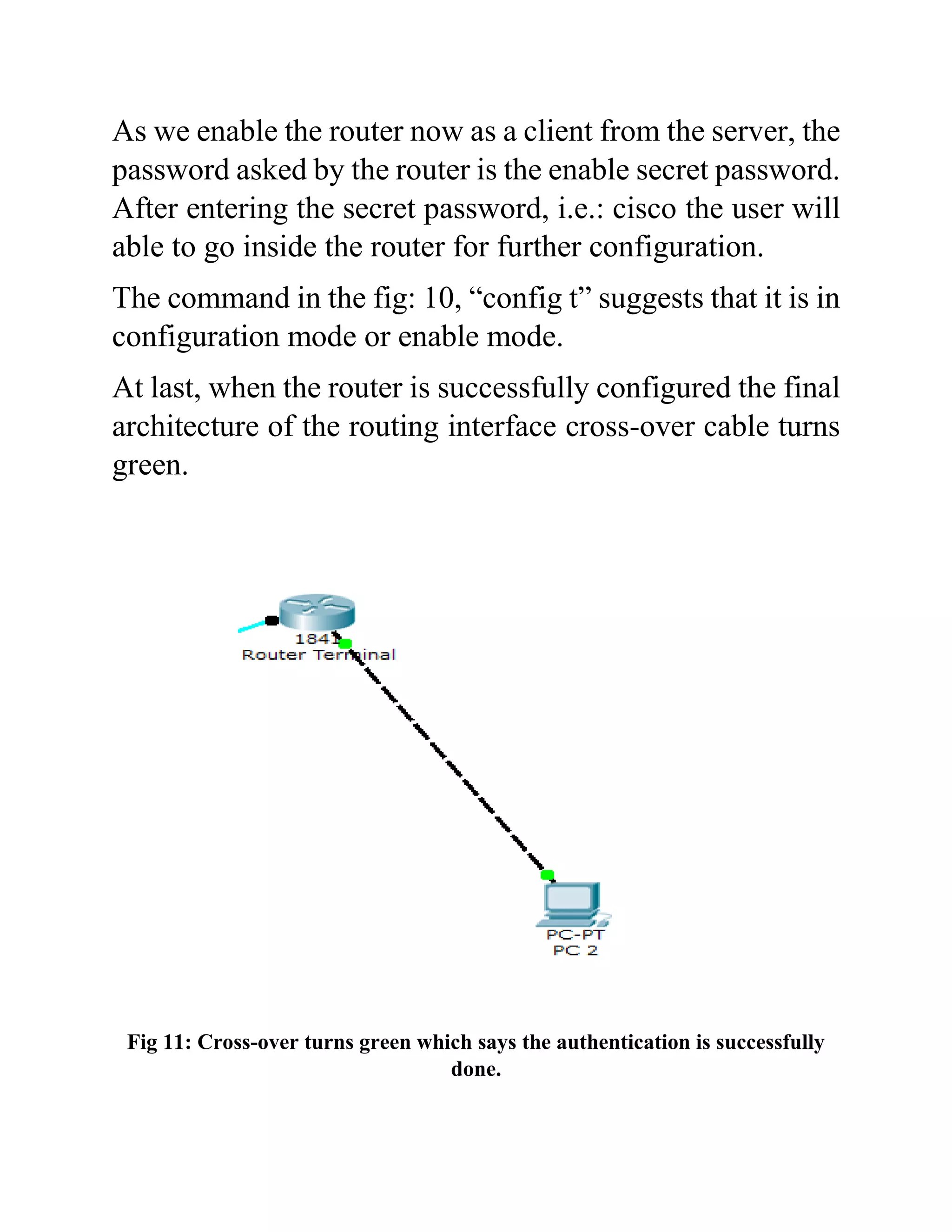
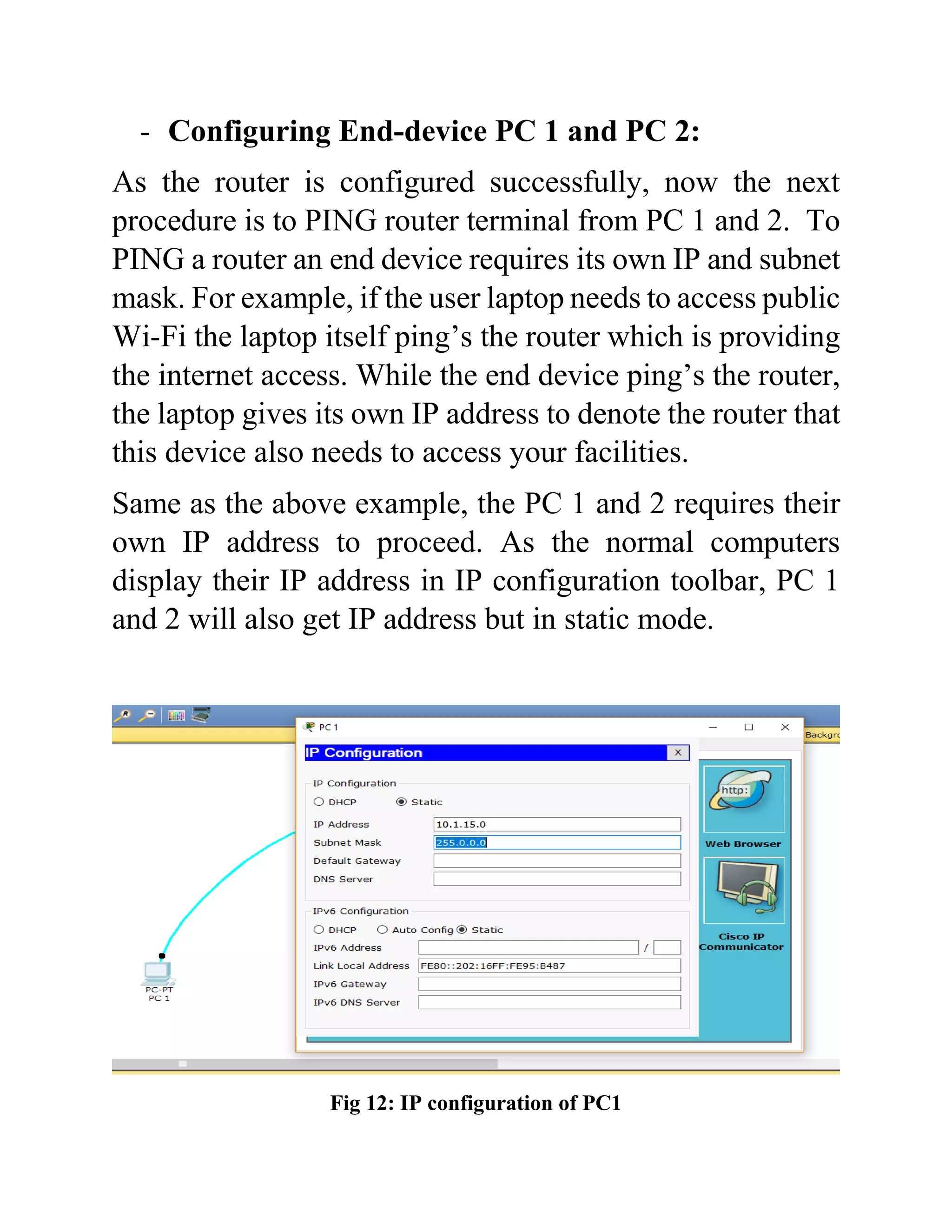
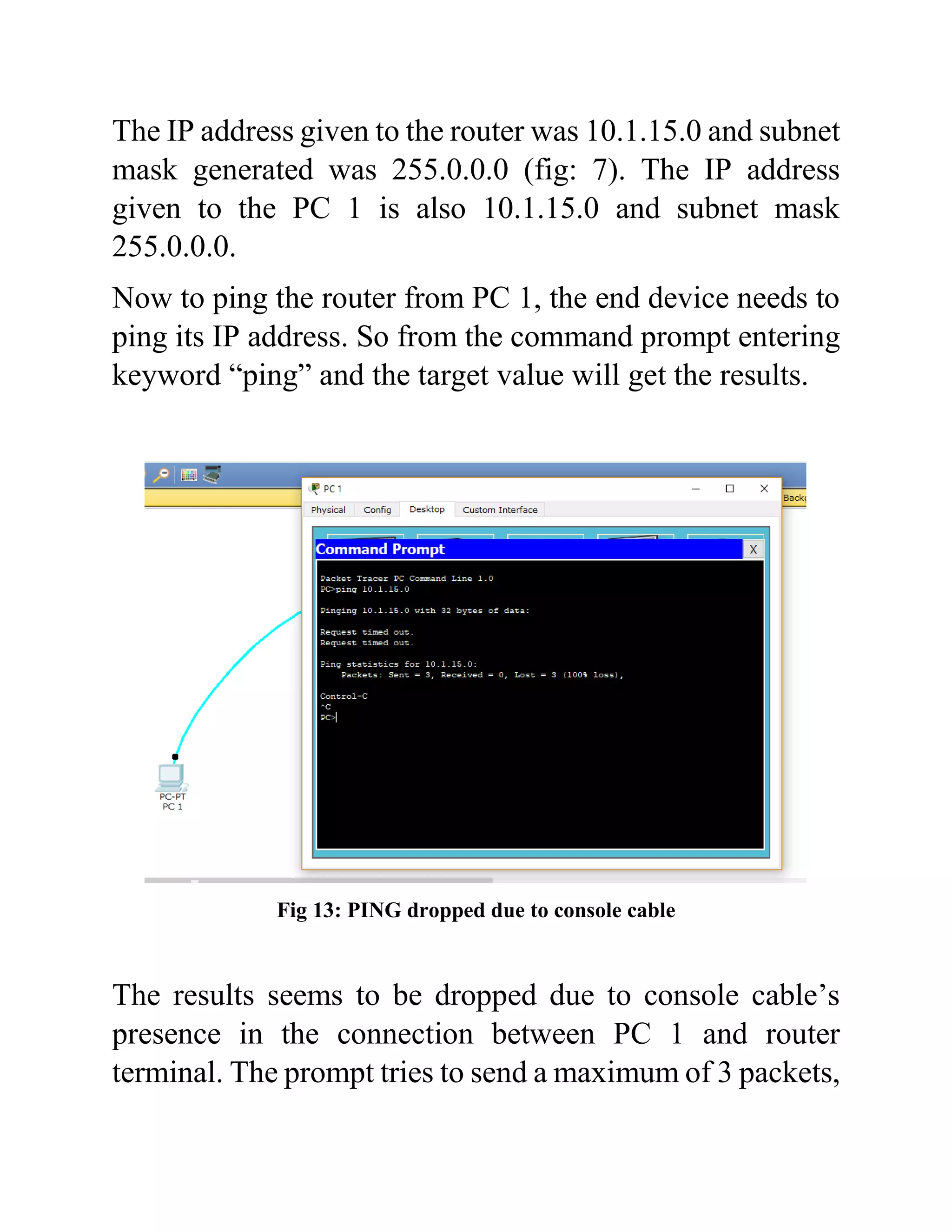
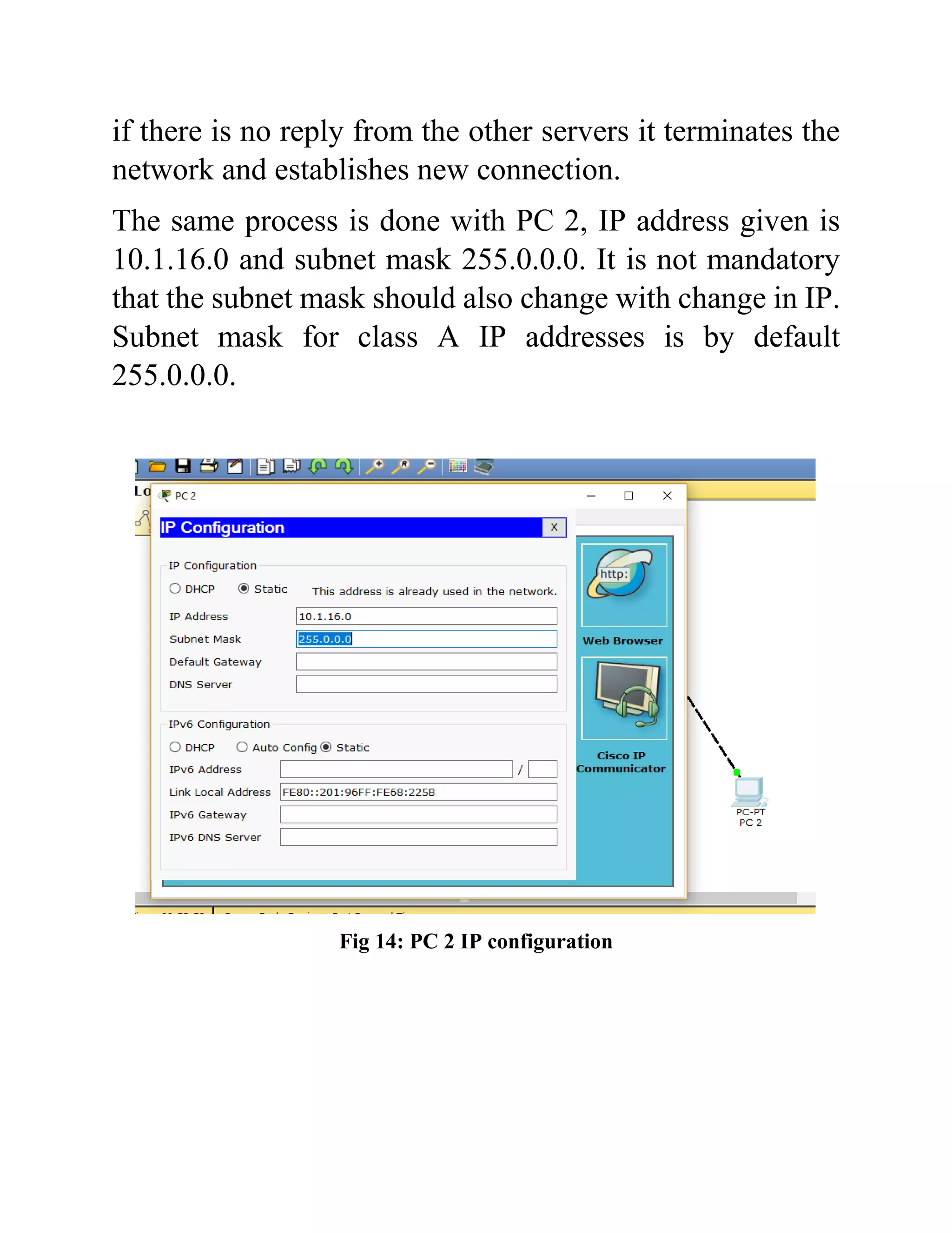
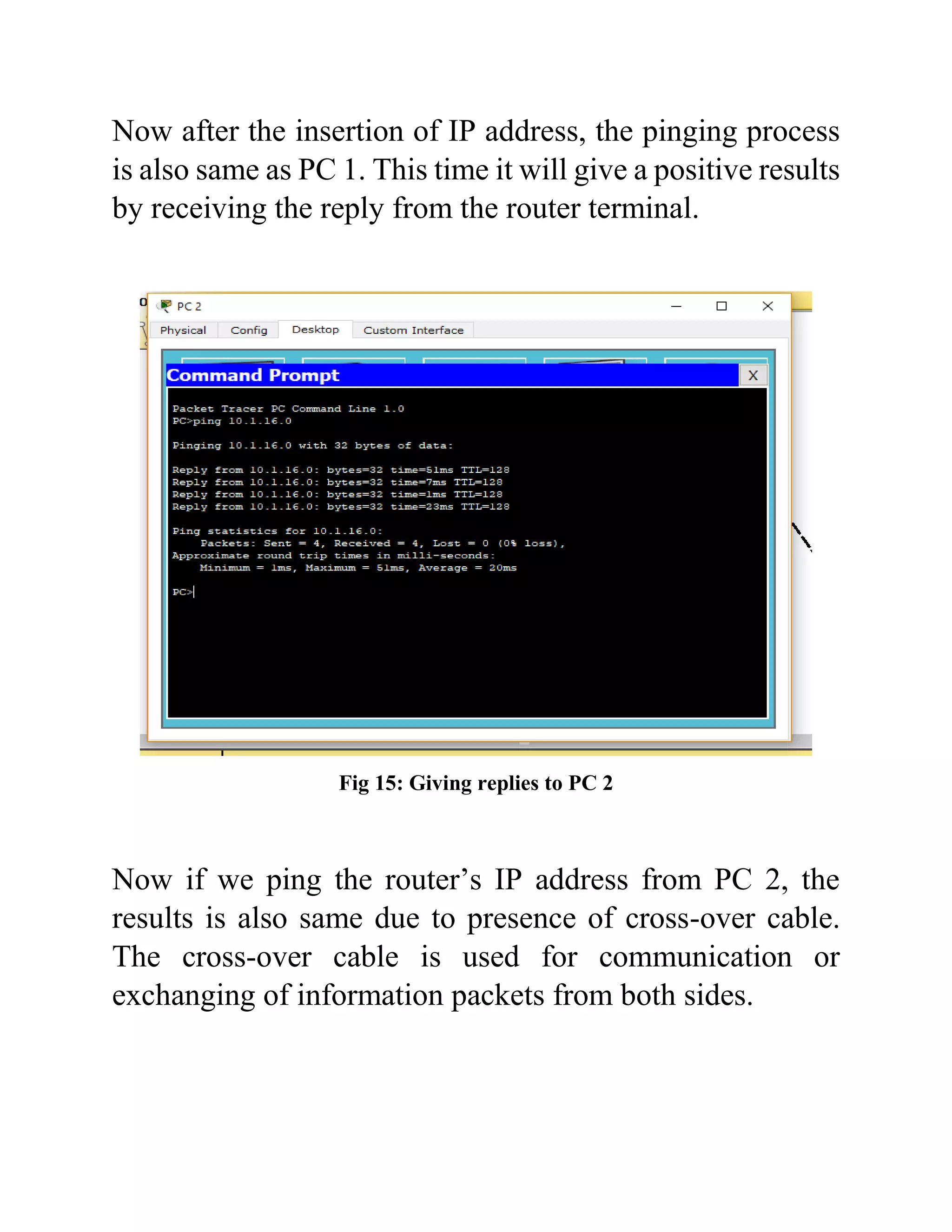
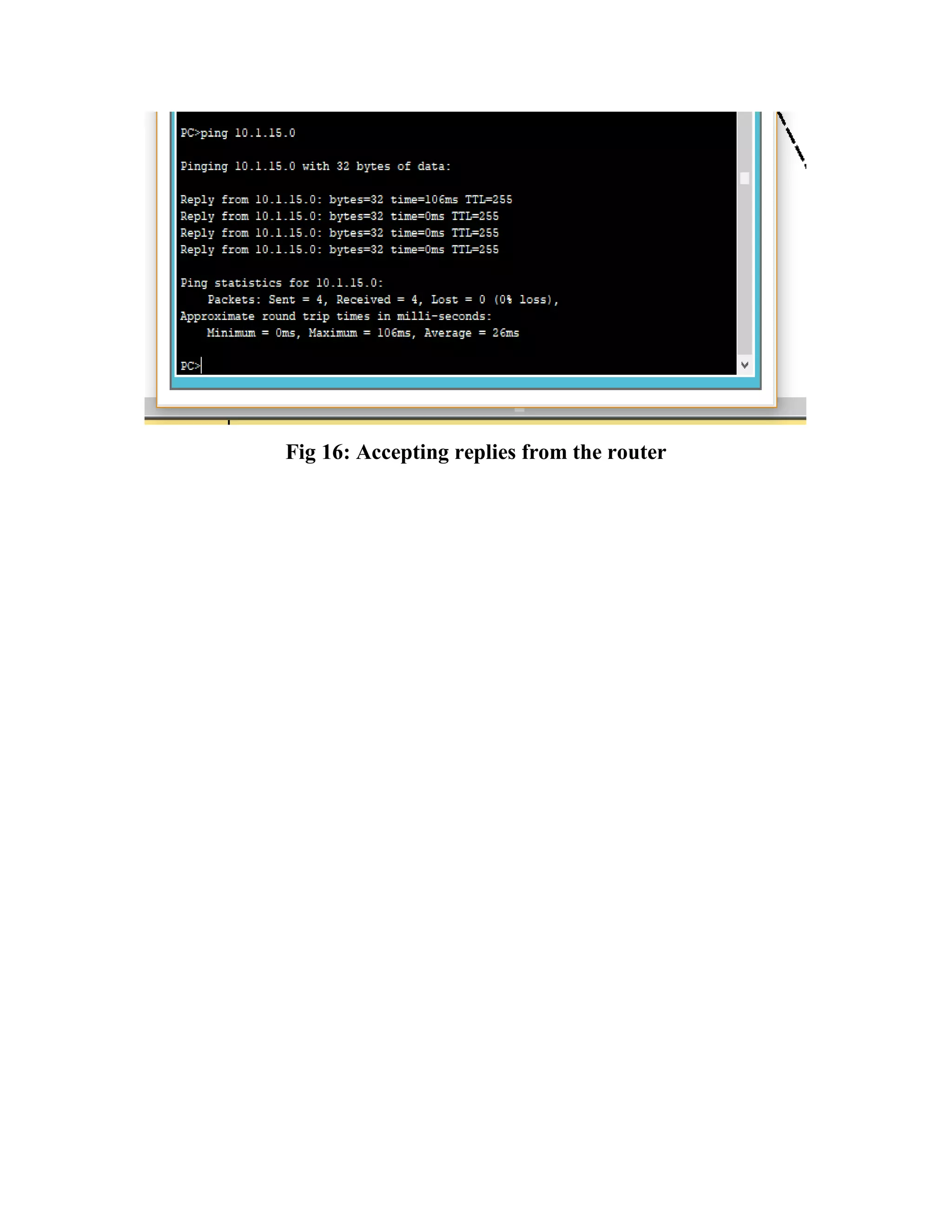
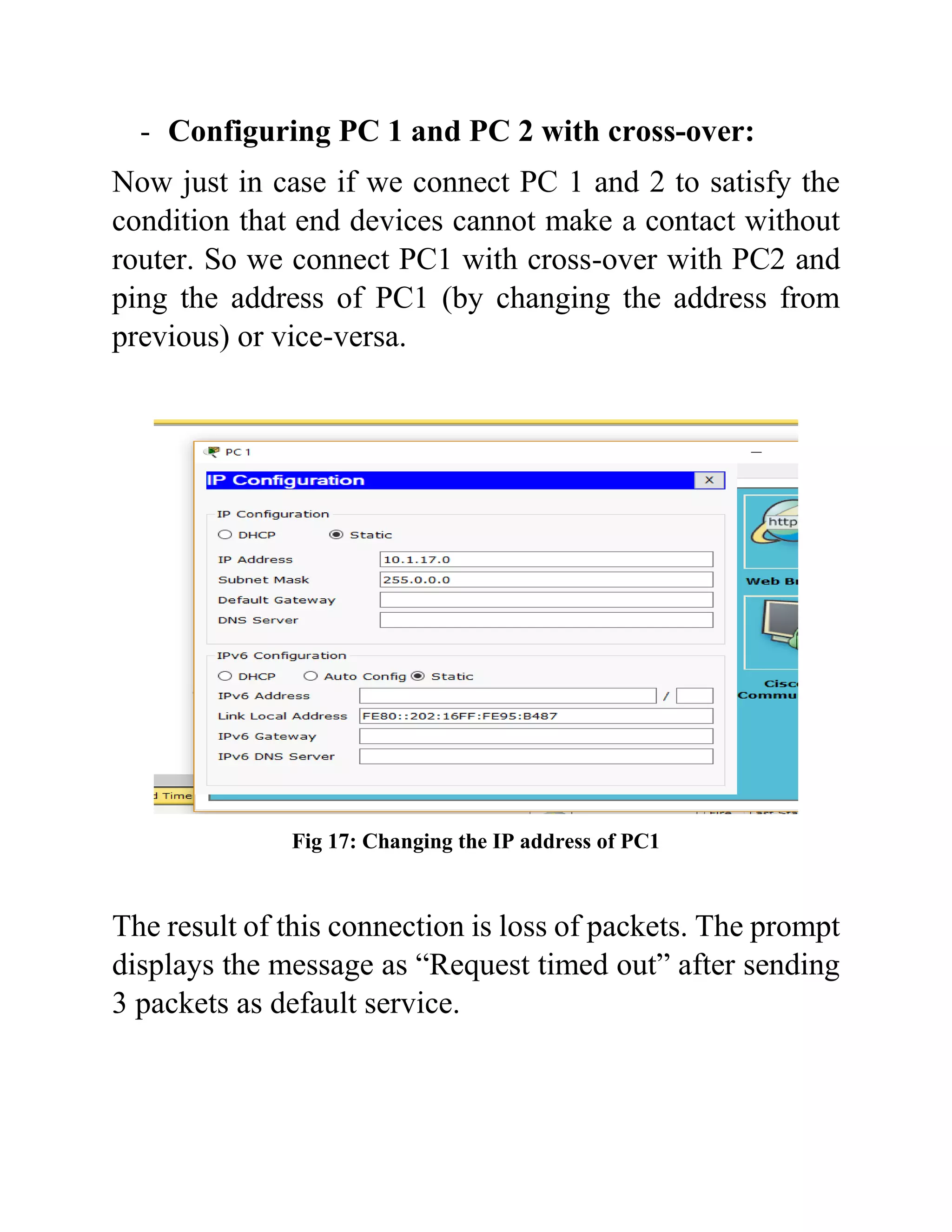
Routing Interface
Configuration using
Cisco Packet Tracer
Created By-
Debjyoti. Saha
Bachelor of Technology
Electronics and Tele-Communication
SVKM’s NMIMS Shirpur Campus
Dhulia, Maharashtra
Date-
April 2019
Abstract
Routing Configuration and Interface of router with
millions of PC’s are easiest way to complete the work of
networking. The study of cisco routers, cables gives a way
of performing the experiment successfully. The basic need
for this experiment is the software known as “Cisco Packet
Tracer”. This software has an inbuilt configuration and can
be compared with Network Simulators. In this project, the
demonstration of whether the router is configured correctly
in port with console as well as cross-over cable. Assigning
of IP addresses and also checking the transmission of
packets by associating Packet Internet Groper (PING) in
command prompt. Connecting the PC’s with router for the
exchange of information becomes conventional method as
PC’s cannot transmit data of their own. Fast Ethernet
connectivity with the ports between router and the PC’s
and enabling the Ethernet verifies whether the router is
receiving information packet or not.
In this project we will not use Simple Network Message
Protocol (SNMP), because we are not considering the data
transfer between the PC and Router. But we are just
configuring that the PC is able to transfer and router is able
to receive the correct sequence of data.
Table of Contents
S.No. Topics Page
No.
1. Introduction 1
2. Architecture 3
3. Project Description 6
4. Development Process 9
5. Conclusions 24
6. References 26
1. Introduction
Routers are a kind of switch which can transfer the data or
packets from the end users to their appropriate destination.
The routers which can be interfaced with millions of end
user devices have to forward the packets with that speed
too. Generally, a router can be connected to at least two
networks, LANs and WANs or its ISP networks. Routers
are situated at the gateway, were two or more networks are
connected.
As we know, the routers are essential for forwarding the
packets, though they can also perform the function of
traffic directing in internet. The clearance of path of web
pages, email is done by the routers to reach destination as
soon as possible.
There are several types of routers, but generally they are
considered as consumer routers and commercial routers.
Commercial routers are those which has the ability to give
access to public. These routers are used in crowded area
such as coffee shops, businesses, hospitals or in
universities. Commercial routers don’t have any security
passwords or any other issues, though they can be easily
hacked.
Consumer’s router are used for small businesses, or in your
residence. Normally this routers has tight security and
cannot be hacked easily. The router generally serves on
wireless access points (WAPs). These routers can used as
switches and also has varieties in it. The pricing of routers
ranges from lower to higher with the specifications of
number of access users. Though there is range of pricing,
the firewall for these routers are same throughout.
2. Architecture
The architecture of Routing Interface Configuration
consists of Router 1841, Generic PC 1 and PC 2. Router
1841 has the property of auxiliary, console and fast
Ethernet.
- Auxiliary Port:
Auxiliary port is used for the connection which is being
initiated soon. This port has a capability to accept the data
packet if it consists of any error. There is no Control
Redundancy Check (CRC) or Frame Checking System
(FRS) in this port.
- Console Port/Cable:
Console is type of cable used for configuration purposes.
The port availability is used to connect console cable to the
router. This port has CRC system and can only accept from
outer end devices.
- Fast Ethernet 0/0 and 0/1:
The Ethernet connectivity is also available in router 1841.
Ethernet describes which port and cable to be used for
internet connectivity, two ports are mandatory available in
every router. They are “0/0” and “0/1”. Ethernet cable port
are also available in end devices, but only one port is to be
used at a time. Router can give access to data connectivity
to multiple devices, but the end devices can access internet
through one connection.
Fig 1: Architecture of Router Interface Configuration, Console (Blue) &
Cross-over (Breaking Black)
As the console cable is for transfer of data from one device
to another, though this cable is not used for long
connectivity. To overcome this drawback a new type of
connection, cross-over cable is used. This cable is used for
both receiving and transmitting of data packets.
3. Project Description
The description of this experiment goes with the procedure
of:
- Connection of router with end devices.
- Port connection.
- Router/Devices Connectivity:
Router 1841 will be the central device of this experiment,
which contains both Ethernet and console connectivity.
End devices in this experiment used are only two, but in
real world millions of computers are used and connected
with single router and this router is used as a switch.
We have used here two end devices which are generic
computers. Generic computer 1 (PC 1) is connected with
console cable to the router 1841. The connection of console
cable is done with the console port of router so that the
results are accurate. This PC is only used for connectivity
verification. On other hand, generic computer 2 (PC 2) is
connected with cross-over cable to the router 1841. Cross-
over cables are connected with fast Ethernet terminal,
because this cable requires internet connectivity. This PC
is used for both packet transmission and receiver.
- Procedure of Port Connection:
Generic PC contains RS232 port to which console cable is
connected. RS232 is a standard serial communication
protocol, it is used for connecting peripheral devices to
allow the exchange of data serially. The console port is
extended to router and connected to the console port.
The second generic PC is connected with the help of fast
Ethernet. Connect the cross-over cable to any port of
Ethernet, but the port of Ethernet should be same for both
the devices.
Fig 2: Final Architecture after Port Connectivity
4. Development Process
The development process turns out in 3 steps:
- Configuring Router 1841.
- Configuring PC1 and PC2 with router.
- Configuring PC1 and PC2 through cross-over.
- Configuring Router 1841
The first step to configure router is to get inserted
Command Line Interface (CLI). While entering the CLI,
the software asks the configuration dialog. If we say “yes”
the software access to the further interface procedure. If
“no” the software terminates the process and ends the
configuration.
Fig 3: CLI Configuration Dialog
After giving the command “yes” the router terminal will
ask for its host name and passwords. The router 1841
consists of 3 main passwords: enable secret, enable
password and virtual terminal password. Enable secret is
the strongest password amongst the 3, though the weakest
password is enable password. While connecting with the
domain, if the user sends its enable password rather than
enable secret then the system router can be easily hacked
the fake server.
Fig 4: Password enabling window in Router Terminal
Whenever an authentication procedure is initialized, only
enable secret is given for access as this password does not
reveal any identity.
To interface the router terminal, all the 3 passwords are
given. Due to this the IOS can determine that the router is
enable for further process and also can be access by any of
the 3 passwords. After giving the passwords, the router
terminal will require an authentication for SNMP which in
short is a formality for message transfer. In this process, we
are not transferring any message packet but just a
connection interface between routers and PC’s.
Fig 5: Router Interface password configuration
Command assigned to SNMP is “no”, which in final
display will give us the interface summary.
Fig 6: Interface Summary
The summary of our router consists of interface elements,
IP addresses, method status and protocol. To get access to
any one of the interface, the command is “fastethernet0/0”
which means we are accessing the fastethernet0/0
interface.
After entering in the current interface, the packet tracer will
ask for IP address and subnet mask. Proceedings will be the
script summary of our router terminal.
Fig 7: Configuration command script
The Fig 7 denotes the complete script generated by the
router 1841. Here we can see all the 3 passwords, interfaces
with their IP. As we have entered in fastethernet0/0
interface, only that interface is open and the others are
shutdown. Which implies that at this point we can only
access that particular interface.
As said earlier, the strongest password among the 3 is the
enable secret. In Fig 8 we can the 3 passwords, enable
secret, enable password and virtual.
Fig 8: Password display to the client
The first command in the figure is enable secret password,
which was given as “cisco” earlier. But as the client is
accessing the router, no other user except the server itself
can see the password. After this naming configuration the
data is to save in Non-volatile RAM (NVRAM) for further
process.
Fig 9: NVRAM configuration save
As the commands are used CLI, the procedure is to press
the “enter” key and we will able to see that the router
terminal configured properly without any error.
Fig 10: CLI inside Router terminal
As we enable the router now as a client from the server, the
password asked by the router is the enable secret password.
After entering the secret password, i.e.: cisco the user will
able to go inside the router for further configuration.
The command in the fig: 10, “config t” suggests that it is in
configuration mode or enable mode.
At last, when the router is successfully configured the final
architecture of the routing interface cross-over cable turns
green.
Fig 11: Cross-over turns green which says the authentication is successfully
done.
- Configuring End-device PC 1 and PC 2:
As the router is configured successfully, now the next
procedure is to PING router terminal from PC 1 and 2. To
PING a router an end device requires its own IP and subnet
mask. For example, if the user laptop needs to access public
Wi-Fi the laptop itself ping’s the router which is providing
the internet access. While the end device ping’s the router,
the laptop gives its own IP address to denote the router that
this device also needs to access your facilities.
Same as the above example, the PC 1 and 2 requires their
own IP address to proceed. As the normal computers
display their IP address in IP configuration toolbar, PC 1
and 2 will also get IP address but in static mode.
Fig 12: IP configuration of PC1
The IP address given to the router was 10.1.15.0 and subnet
mask generated was 255.0.0.0 (fig: 7). The IP address
given to the PC 1 is also 10.1.15.0 and subnet mask
255.0.0.0.
Now to ping the router from PC 1, the end device needs to
ping its IP address. So from the command prompt entering
keyword “ping” and the target value will get the results.
Fig 13: PING dropped due to console cable
The results seems to be dropped due to console cable’s
presence in the connection between PC 1 and router
terminal. The prompt tries to send a maximum of 3 packets,
if there is no reply from the other servers it terminates the
network and establishes new connection.
The same process is done with PC 2, IP address given is
10.1.16.0 and subnet mask 255.0.0.0. It is not mandatory
that the subnet mask should also change with change in IP.
Subnet mask for class A IP addresses is by default
255.0.0.0.
Fig 14: PC 2 IP configuration
Now after the insertion of IP address, the pinging process
is also same as PC 1. This time it will give a positive results
by receiving the reply from the router terminal.
Fig 15: Giving replies to PC 2
Now if we ping the router’s IP address from PC 2, the
results is also same due to presence of cross-over cable.
The cross-over cable is used for communication or
exchanging of information packets from both sides.
Fig 16: Accepting replies from the router
- Configuring PC 1 and PC 2 with cross-over:
Now just in case if we connect PC 1 and 2 to satisfy the
condition that end devices cannot make a contact without
router. So we connect PC1 with cross-over with PC2 and
ping the address of PC1 (by changing the address from
previous) or vice-versa.
Fig 17: Changing the IP address of PC1
The result of this connection is loss of packets. The prompt
displays the message as “Request timed out” after sending
3 packets as default service.
Fig 18: PING dropped due to connectivity between two end devices
5. Conclusions
- The final conclusion on this project is that the
connections used in the network, i.e.: console cable
and cross-over are for communication from one-to-
one devices.
- No two end devices can communicate or exchange
packets by themselves without any connection from
the router.
- Console cables are not used for sending information
packets to the router, rather than use of cross-over
cables are prescribed.
- Subnet mask of two different devices can be same if
the IP address classes are same.
- Correct Ethernet connectivity with the router denotes
the connection to be green.
- By default, the end device sends 3 packets for service,
if the feedback is positive it continue to send.
6. References
- https://www.netacad.com/courses/packet-tracer
- https://www.cisco.com/c/dam/en_us/training-
events/netacad/course_catalog/docs/Cisco_PacketTra
cer_DS.pdf
- https://www.manageengine.com/network-
monitoring/interface-monitor-
templates.html?network=g&device=c&keyword=%2
Brouter%2Binterface&campaignid=1686562928&cre
ative=327666548841&matchtype=b&adposition=1t1
&placement=&adgroup=66508623540&targetid=kw
d-
601067346373&location=1007788&gclid=Cj0KCQj
wuLPnBRDjARIsACDzGL2ZjTiOtCss2J_0CWYKb
8JyLHwaYQHLw763Ft6ulQIQKX0h7Nd-
xOoaAreHEALw_wcB
- https://circuitdigest.com/article/rs232-serial-
communication-protocol-basics-specifications
- https://www.webopedia.com/TERM/R/router.html
- https://www.techopedia.com/definition/4981/internet
-protocol-configuration-ipconfig
- https://www.cisco.com/c/en/us/products/ios-nx-os-
software/ios-technologies/index.html

Report on routing interface configuration

  • 1.
    Routing Interface Configuration using CiscoPacket Tracer Created By- Debjyoti. Saha Bachelor of Technology Electronics and Tele-Communication SVKM’s NMIMS Shirpur Campus Dhulia, Maharashtra Date- April 2019
  • 2.
    Abstract Routing Configuration andInterface of router with millions of PC’s are easiest way to complete the work of networking. The study of cisco routers, cables gives a way of performing the experiment successfully. The basic need for this experiment is the software known as “Cisco Packet Tracer”. This software has an inbuilt configuration and can be compared with Network Simulators. In this project, the demonstration of whether the router is configured correctly in port with console as well as cross-over cable. Assigning of IP addresses and also checking the transmission of packets by associating Packet Internet Groper (PING) in command prompt. Connecting the PC’s with router for the exchange of information becomes conventional method as PC’s cannot transmit data of their own. Fast Ethernet connectivity with the ports between router and the PC’s and enabling the Ethernet verifies whether the router is receiving information packet or not. In this project we will not use Simple Network Message Protocol (SNMP), because we are not considering the data transfer between the PC and Router. But we are just configuring that the PC is able to transfer and router is able to receive the correct sequence of data.
  • 3.
    Table of Contents S.No.Topics Page No. 1. Introduction 1 2. Architecture 3 3. Project Description 6 4. Development Process 9 5. Conclusions 24 6. References 26
  • 4.
    1. Introduction Routers area kind of switch which can transfer the data or packets from the end users to their appropriate destination. The routers which can be interfaced with millions of end user devices have to forward the packets with that speed too. Generally, a router can be connected to at least two networks, LANs and WANs or its ISP networks. Routers are situated at the gateway, were two or more networks are connected. As we know, the routers are essential for forwarding the packets, though they can also perform the function of traffic directing in internet. The clearance of path of web pages, email is done by the routers to reach destination as soon as possible. There are several types of routers, but generally they are considered as consumer routers and commercial routers. Commercial routers are those which has the ability to give access to public. These routers are used in crowded area such as coffee shops, businesses, hospitals or in universities. Commercial routers don’t have any security passwords or any other issues, though they can be easily hacked. Consumer’s router are used for small businesses, or in your residence. Normally this routers has tight security and
  • 5.
    cannot be hackedeasily. The router generally serves on wireless access points (WAPs). These routers can used as switches and also has varieties in it. The pricing of routers ranges from lower to higher with the specifications of number of access users. Though there is range of pricing, the firewall for these routers are same throughout.
  • 6.
    2. Architecture The architectureof Routing Interface Configuration consists of Router 1841, Generic PC 1 and PC 2. Router 1841 has the property of auxiliary, console and fast Ethernet. - Auxiliary Port: Auxiliary port is used for the connection which is being initiated soon. This port has a capability to accept the data packet if it consists of any error. There is no Control Redundancy Check (CRC) or Frame Checking System (FRS) in this port. - Console Port/Cable: Console is type of cable used for configuration purposes. The port availability is used to connect console cable to the router. This port has CRC system and can only accept from outer end devices. - Fast Ethernet 0/0 and 0/1: The Ethernet connectivity is also available in router 1841. Ethernet describes which port and cable to be used for internet connectivity, two ports are mandatory available in
  • 7.
    every router. Theyare “0/0” and “0/1”. Ethernet cable port are also available in end devices, but only one port is to be used at a time. Router can give access to data connectivity to multiple devices, but the end devices can access internet through one connection. Fig 1: Architecture of Router Interface Configuration, Console (Blue) & Cross-over (Breaking Black) As the console cable is for transfer of data from one device to another, though this cable is not used for long connectivity. To overcome this drawback a new type of
  • 8.
    connection, cross-over cableis used. This cable is used for both receiving and transmitting of data packets.
  • 9.
    3. Project Description Thedescription of this experiment goes with the procedure of: - Connection of router with end devices. - Port connection. - Router/Devices Connectivity: Router 1841 will be the central device of this experiment, which contains both Ethernet and console connectivity. End devices in this experiment used are only two, but in real world millions of computers are used and connected with single router and this router is used as a switch. We have used here two end devices which are generic computers. Generic computer 1 (PC 1) is connected with console cable to the router 1841. The connection of console cable is done with the console port of router so that the results are accurate. This PC is only used for connectivity verification. On other hand, generic computer 2 (PC 2) is connected with cross-over cable to the router 1841. Cross- over cables are connected with fast Ethernet terminal, because this cable requires internet connectivity. This PC is used for both packet transmission and receiver.
  • 10.
    - Procedure ofPort Connection: Generic PC contains RS232 port to which console cable is connected. RS232 is a standard serial communication protocol, it is used for connecting peripheral devices to allow the exchange of data serially. The console port is extended to router and connected to the console port. The second generic PC is connected with the help of fast Ethernet. Connect the cross-over cable to any port of Ethernet, but the port of Ethernet should be same for both the devices. Fig 2: Final Architecture after Port Connectivity
  • 11.
    4. Development Process Thedevelopment process turns out in 3 steps: - Configuring Router 1841. - Configuring PC1 and PC2 with router. - Configuring PC1 and PC2 through cross-over. - Configuring Router 1841 The first step to configure router is to get inserted Command Line Interface (CLI). While entering the CLI, the software asks the configuration dialog. If we say “yes” the software access to the further interface procedure. If “no” the software terminates the process and ends the configuration.
  • 12.
    Fig 3: CLIConfiguration Dialog After giving the command “yes” the router terminal will ask for its host name and passwords. The router 1841 consists of 3 main passwords: enable secret, enable password and virtual terminal password. Enable secret is the strongest password amongst the 3, though the weakest password is enable password. While connecting with the domain, if the user sends its enable password rather than enable secret then the system router can be easily hacked the fake server.
  • 13.
    Fig 4: Passwordenabling window in Router Terminal Whenever an authentication procedure is initialized, only enable secret is given for access as this password does not reveal any identity. To interface the router terminal, all the 3 passwords are given. Due to this the IOS can determine that the router is enable for further process and also can be access by any of the 3 passwords. After giving the passwords, the router terminal will require an authentication for SNMP which in short is a formality for message transfer. In this process, we are not transferring any message packet but just a connection interface between routers and PC’s.
  • 14.
    Fig 5: RouterInterface password configuration Command assigned to SNMP is “no”, which in final display will give us the interface summary. Fig 6: Interface Summary
  • 15.
    The summary ofour router consists of interface elements, IP addresses, method status and protocol. To get access to any one of the interface, the command is “fastethernet0/0” which means we are accessing the fastethernet0/0 interface. After entering in the current interface, the packet tracer will ask for IP address and subnet mask. Proceedings will be the script summary of our router terminal. Fig 7: Configuration command script
  • 16.
    The Fig 7denotes the complete script generated by the router 1841. Here we can see all the 3 passwords, interfaces with their IP. As we have entered in fastethernet0/0 interface, only that interface is open and the others are shutdown. Which implies that at this point we can only access that particular interface. As said earlier, the strongest password among the 3 is the enable secret. In Fig 8 we can the 3 passwords, enable secret, enable password and virtual. Fig 8: Password display to the client The first command in the figure is enable secret password, which was given as “cisco” earlier. But as the client is accessing the router, no other user except the server itself can see the password. After this naming configuration the data is to save in Non-volatile RAM (NVRAM) for further process.
  • 17.
    Fig 9: NVRAMconfiguration save As the commands are used CLI, the procedure is to press the “enter” key and we will able to see that the router terminal configured properly without any error. Fig 10: CLI inside Router terminal
  • 18.
    As we enablethe router now as a client from the server, the password asked by the router is the enable secret password. After entering the secret password, i.e.: cisco the user will able to go inside the router for further configuration. The command in the fig: 10, “config t” suggests that it is in configuration mode or enable mode. At last, when the router is successfully configured the final architecture of the routing interface cross-over cable turns green. Fig 11: Cross-over turns green which says the authentication is successfully done.
  • 19.
    - Configuring End-devicePC 1 and PC 2: As the router is configured successfully, now the next procedure is to PING router terminal from PC 1 and 2. To PING a router an end device requires its own IP and subnet mask. For example, if the user laptop needs to access public Wi-Fi the laptop itself ping’s the router which is providing the internet access. While the end device ping’s the router, the laptop gives its own IP address to denote the router that this device also needs to access your facilities. Same as the above example, the PC 1 and 2 requires their own IP address to proceed. As the normal computers display their IP address in IP configuration toolbar, PC 1 and 2 will also get IP address but in static mode. Fig 12: IP configuration of PC1
  • 20.
    The IP addressgiven to the router was 10.1.15.0 and subnet mask generated was 255.0.0.0 (fig: 7). The IP address given to the PC 1 is also 10.1.15.0 and subnet mask 255.0.0.0. Now to ping the router from PC 1, the end device needs to ping its IP address. So from the command prompt entering keyword “ping” and the target value will get the results. Fig 13: PING dropped due to console cable The results seems to be dropped due to console cable’s presence in the connection between PC 1 and router terminal. The prompt tries to send a maximum of 3 packets,
  • 21.
    if there isno reply from the other servers it terminates the network and establishes new connection. The same process is done with PC 2, IP address given is 10.1.16.0 and subnet mask 255.0.0.0. It is not mandatory that the subnet mask should also change with change in IP. Subnet mask for class A IP addresses is by default 255.0.0.0. Fig 14: PC 2 IP configuration
  • 22.
    Now after theinsertion of IP address, the pinging process is also same as PC 1. This time it will give a positive results by receiving the reply from the router terminal. Fig 15: Giving replies to PC 2 Now if we ping the router’s IP address from PC 2, the results is also same due to presence of cross-over cable. The cross-over cable is used for communication or exchanging of information packets from both sides.
  • 23.
    Fig 16: Acceptingreplies from the router
  • 24.
    - Configuring PC1 and PC 2 with cross-over: Now just in case if we connect PC 1 and 2 to satisfy the condition that end devices cannot make a contact without router. So we connect PC1 with cross-over with PC2 and ping the address of PC1 (by changing the address from previous) or vice-versa. Fig 17: Changing the IP address of PC1 The result of this connection is loss of packets. The prompt displays the message as “Request timed out” after sending 3 packets as default service.
  • 25.
    Fig 18: PINGdropped due to connectivity between two end devices
  • 26.
    5. Conclusions - Thefinal conclusion on this project is that the connections used in the network, i.e.: console cable and cross-over are for communication from one-to- one devices. - No two end devices can communicate or exchange packets by themselves without any connection from the router. - Console cables are not used for sending information packets to the router, rather than use of cross-over cables are prescribed. - Subnet mask of two different devices can be same if the IP address classes are same. - Correct Ethernet connectivity with the router denotes the connection to be green. - By default, the end device sends 3 packets for service, if the feedback is positive it continue to send.
  • 27.
    6. References - https://www.netacad.com/courses/packet-tracer -https://www.cisco.com/c/dam/en_us/training- events/netacad/course_catalog/docs/Cisco_PacketTra cer_DS.pdf - https://www.manageengine.com/network- monitoring/interface-monitor- templates.html?network=g&device=c&keyword=%2 Brouter%2Binterface&campaignid=1686562928&cre ative=327666548841&matchtype=b&adposition=1t1 &placement=&adgroup=66508623540&targetid=kw d- 601067346373&location=1007788&gclid=Cj0KCQj wuLPnBRDjARIsACDzGL2ZjTiOtCss2J_0CWYKb 8JyLHwaYQHLw763Ft6ulQIQKX0h7Nd- xOoaAreHEALw_wcB - https://circuitdigest.com/article/rs232-serial- communication-protocol-basics-specifications - https://www.webopedia.com/TERM/R/router.html - https://www.techopedia.com/definition/4981/internet -protocol-configuration-ipconfig
  • 28.