INTRODUCTION TO COMPUTERNETWORKS
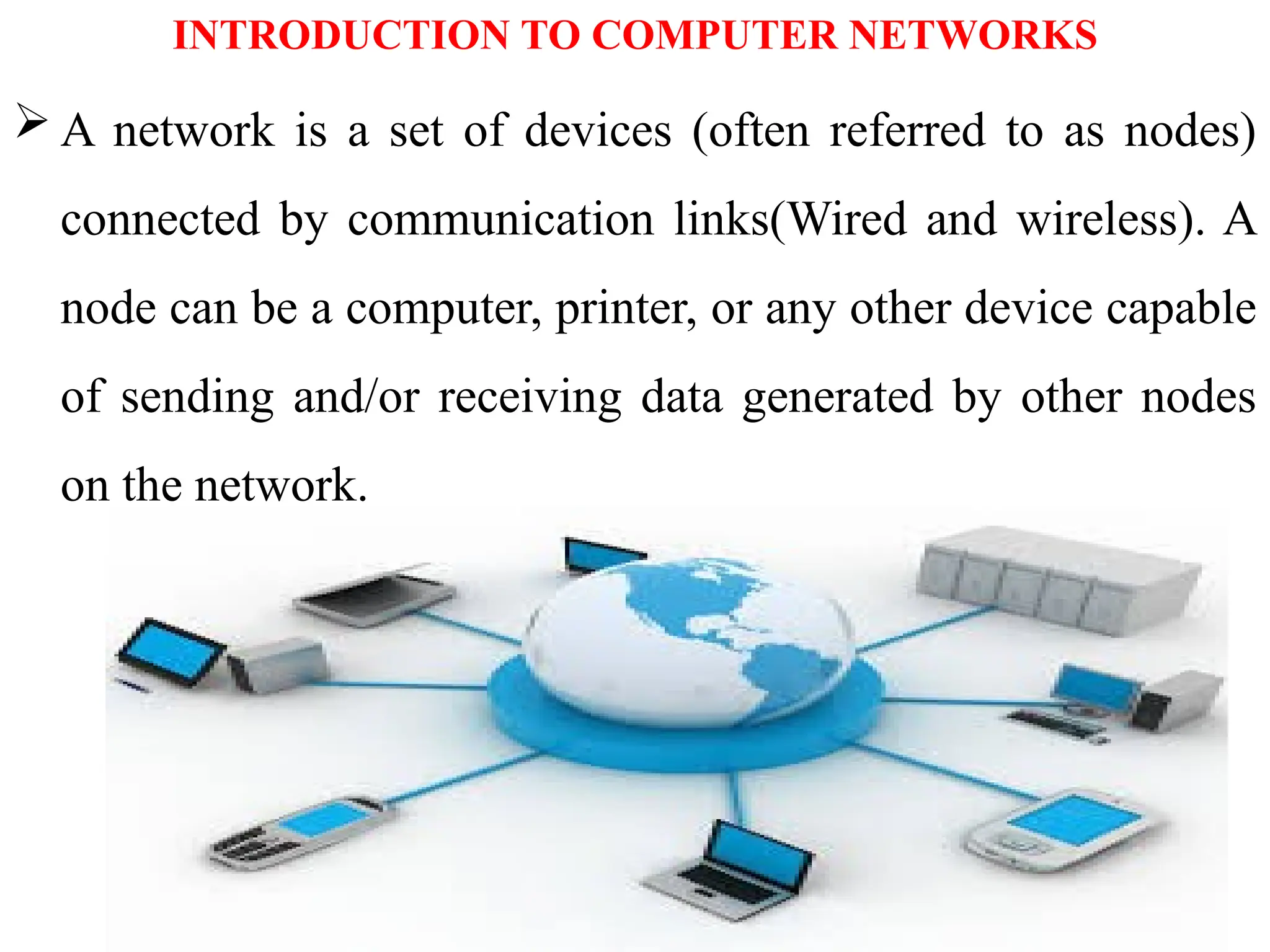
A network is a set of devices (often referred to as nodes)
connected by communication links(Wired and wireless). A
node can be a computer, printer, or any other device capable
of sending and/or receiving data generated by other nodes
on the network.
3.
USES OF COMPUTERNETWORKS/APPLICATIONS OF
COMPUTER NETWORKS
Major application areas of computer network are as follows:
1. Business Applications
2. Home Applications
3. Mobile users
4. Social media
1. Business Applications
Following are some business applications of computer networks:
a. Resource Sharing:
The goal is to make all programs, equipments(like printers
etc), and especially data, available to anyone on the network
without regard to the physical location of the resource and the
user. So, sharing a resource to any device over a network.
4.
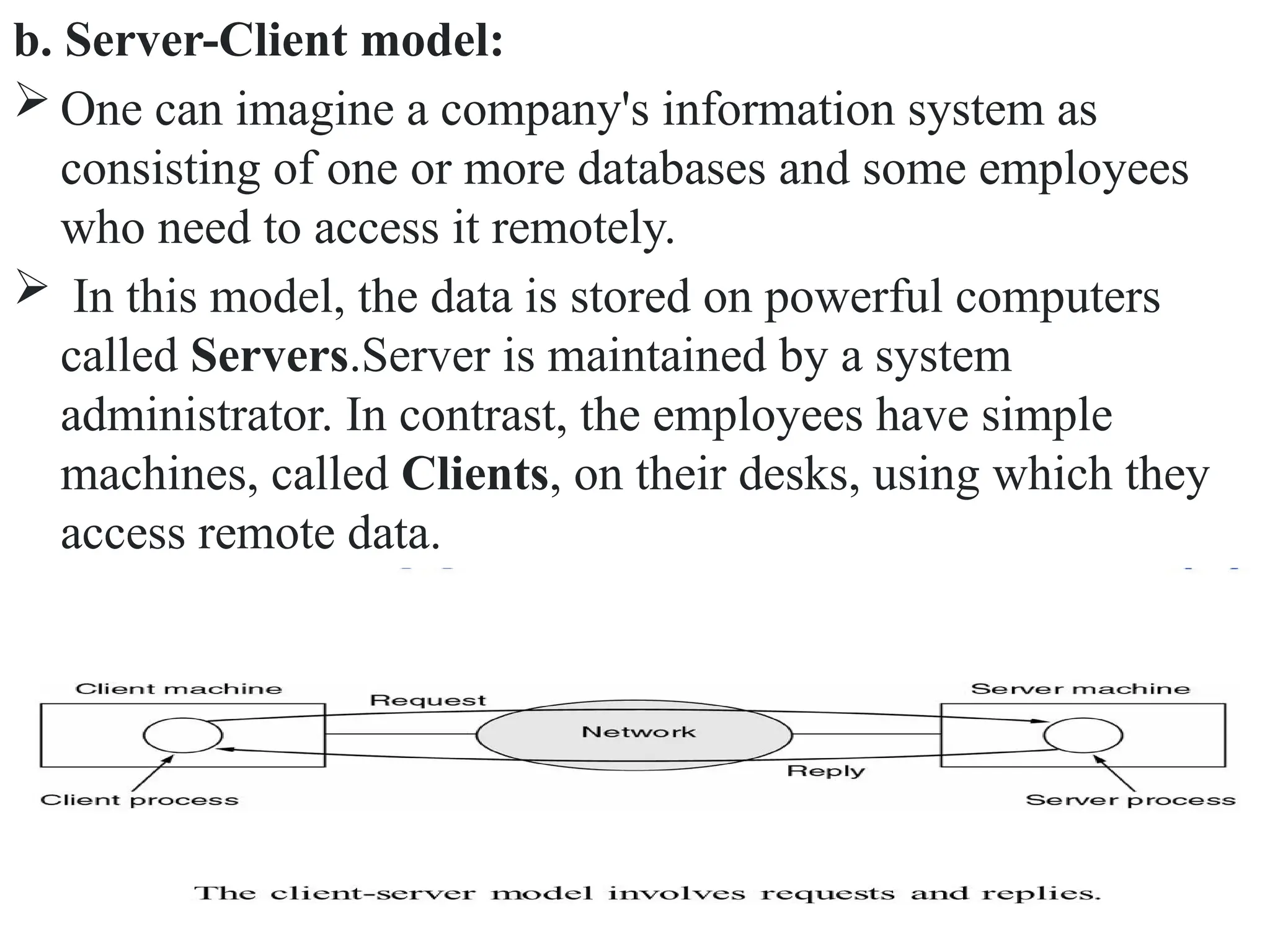
b. Server-Client model:
One can imagine a company's information system as
consisting of one or more databases and some employees
who need to access it remotely.
In this model, the data is stored on powerful computers
called Servers.Server is maintained by a system
administrator. In contrast, the employees have simple
machines, called Clients, on their desks, using which they
access remote data.
5.
c. Communication Medium:
A computer network can provide a powerful communication
medium among employees. Virtually every company that
has two or more computers now has e-mail (electronic
mail), which employees generally use for a great deal of
daily communication.
d. eCommerce:
Computer network is important in business. We can do the
business over the internet.
Doing business electronically with other companies.
Doing business with consumers over the Internet.
Ex: amazon.com is doing their business over the internet.
6.
2. Home Applications
Homes contain many networked devices, e.g., computers,
TVs, connected to the Internet by cable, DSL, wireless, etc.
Home users communicate, e.g., social networks.
Some application use the peer-to-peer model in which there
are no fixed clients and servers.
Some of the most important uses of the Internet for
home users are as follows:
a. Access to remote information
b. Person-to-person communication
c. Interactive entertainment
d. Electronic commerce
7.
a. Access toremote information
It comes in many forms. It can be surfing the World Wide
Web for information. It include online newspaper, accessing
digital library.
b. Person-to-person communication
It includes E-mail, instant messaging, discussion using
worldwide newsgroups, chat rooms etc.
Here every person can communicate with one or more other
people.
8.
c. Interactive entertainment
whichis a huge and growing industry which
includes video on demand, live television etc.
d. Electronic commerce
In home applications, buy or sell items, pay bills,
manage bank accounts, pay taxes, transfer funds and
handle investments electronically.
9.
3. Mobile users
The rapidly growing sectors in computer applications are
mobile devices like notebook computers and PDAs
(personal digital assistants). Here mobile users/device
means portable device. The computer network is widely
used in smartwatches, wearable devices, tablets, online
transactions, purchasing or selling products online, etc.
4. Social media
Social media is also a great example of a computer network
application. It helps people to share and receive any
information related to political, ethical, and social issues.
10.
Components of ComputerNetworks
A data communications system has five components
1. Message: The message is the information (data) to be
communicated. Popular forms of information include text,
numbers, pictures, audio, and video.
2. Sender: The sender is the device that sends the data
message. It can be a computer, workstation, telephone
handset, video camera, and so on.
3. Receiver: The receiver is the device that receives the
message. It can be a computer, workstation, telephone
handset, television, and so on.
11.
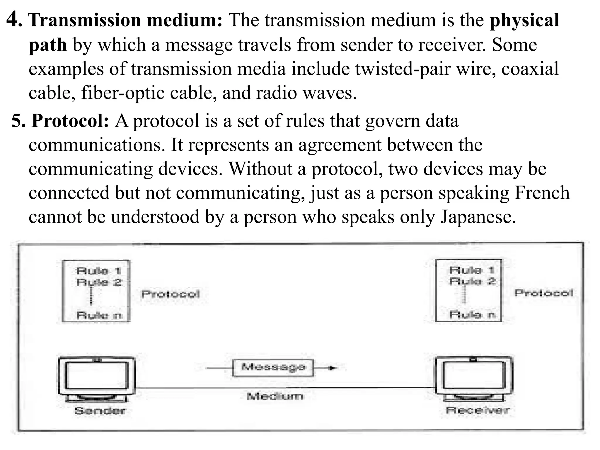
4. Transmission medium:The transmission medium is the physical
path by which a message travels from sender to receiver. Some
examples of transmission media include twisted-pair wire, coaxial
cable, fiber-optic cable, and radio waves.
5. Protocol: A protocol is a set of rules that govern data
communications. It represents an agreement between the
communicating devices. Without a protocol, two devices may be
connected but not communicating, just as a person speaking French
cannot be understood by a person who speaks only Japanese.
12.
Data flow incommunication system or transmission modes
The way in which data is transmitted from one device to
another device is known as transmission mode.
The transmission mode is also known as the
communication mode.
Each communication channel has a direction associated
with it, and transmission media provide the direction.
Therefore, the transmission mode is also known as a
directional mode.
The transmission mode is defined in the physical layer.
The Transmission mode is divided into three categories:
1. Simplex mode
2. Half-duplex mode
3. Full-duplex mode
13.
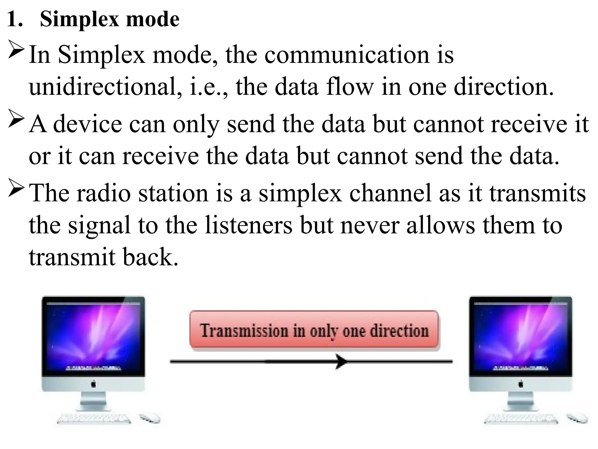
1. Simplex mode
InSimplex mode, the communication is
unidirectional, i.e., the data flow in one direction.
A device can only send the data but cannot receive it
or it can receive the data but cannot send the data.
The radio station is a simplex channel as it transmits
the signal to the listeners but never allows them to
transmit back.
14.
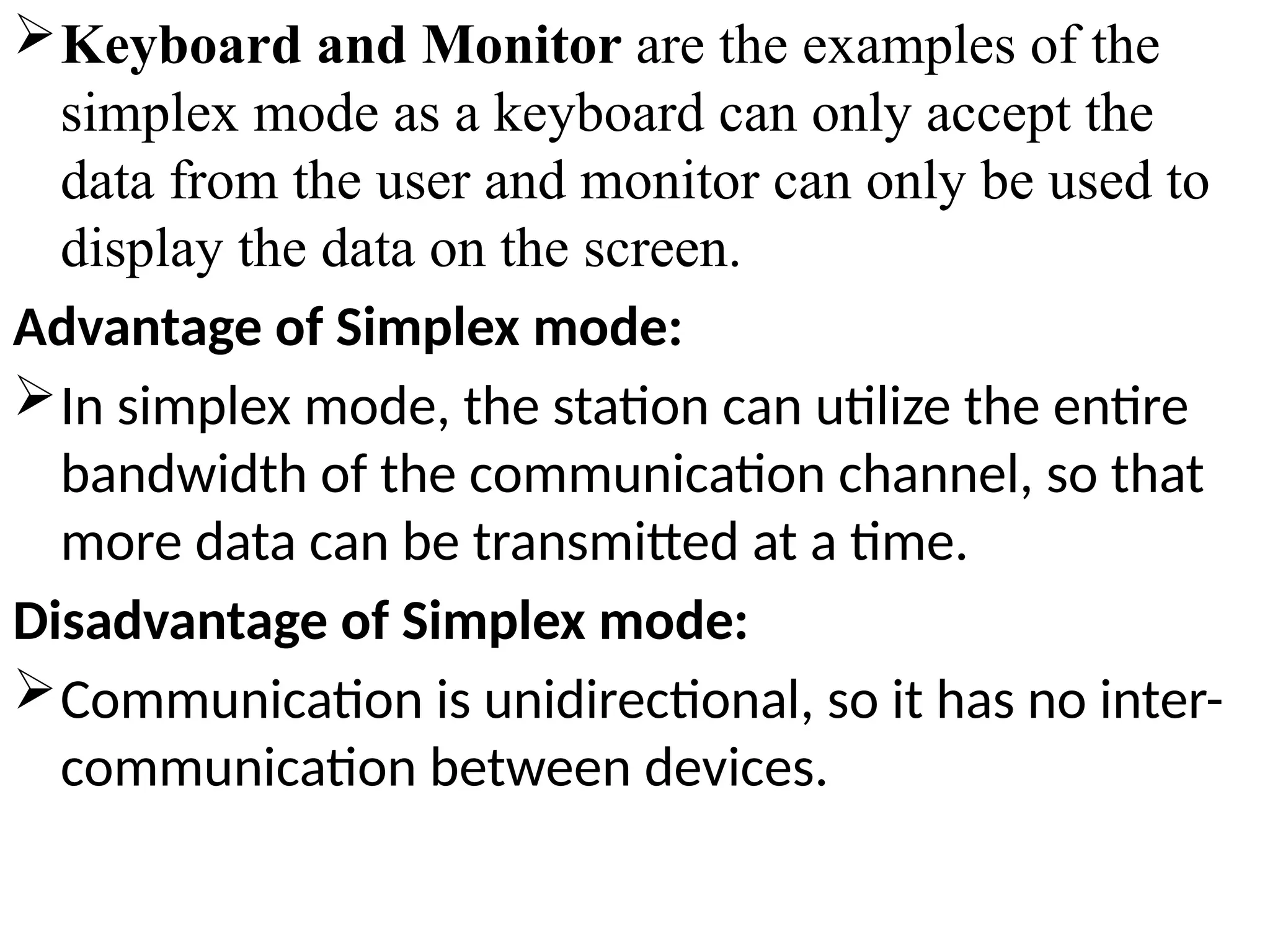
Keyboard and Monitorare the examples of the
simplex mode as a keyboard can only accept the
data from the user and monitor can only be used to
display the data on the screen.
Advantage of Simplex mode:
In simplex mode, the station can utilize the entire
bandwidth of the communication channel, so that
more data can be transmitted at a time.
Disadvantage of Simplex mode:
Communication is unidirectional, so it has no inter-
communication between devices.
15.
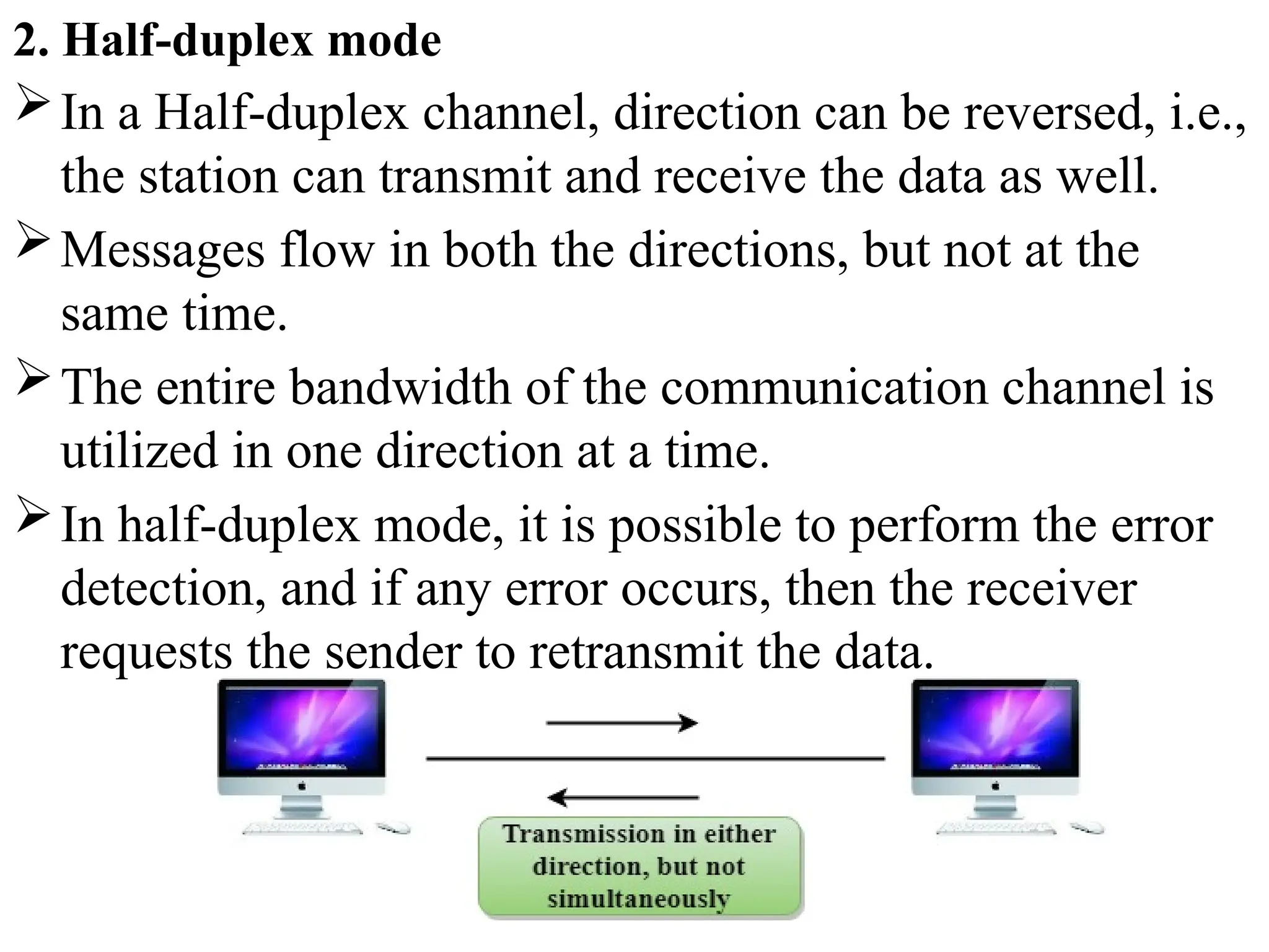
2. Half-duplex mode
Ina Half-duplex channel, direction can be reversed, i.e.,
the station can transmit and receive the data as well.
Messages flow in both the directions, but not at the
same time.
The entire bandwidth of the communication channel is
utilized in one direction at a time.
In half-duplex mode, it is possible to perform the error
detection, and if any error occurs, then the receiver
requests the sender to retransmit the data.
16.
A Walkie-talkieis an example of the Half-duplex mode. In
Walkie-talkie, one party speaks, and another party listens.
After a pause, the other speaks and first party listens.
Speaking simultaneously will create the distorted sound
which cannot be understood.
Advantage of Half-duplex mode:
In half-duplex mode, both the devices can send and receive
the data and also can utilize the entire bandwidth of the
communication channel during the transmission of data.
Disadvantage of Half-Duplex mode:
In half-duplex mode, when one device is sending the data,
then another has to wait, this causes the delay in sending the
data at the right time.
17.
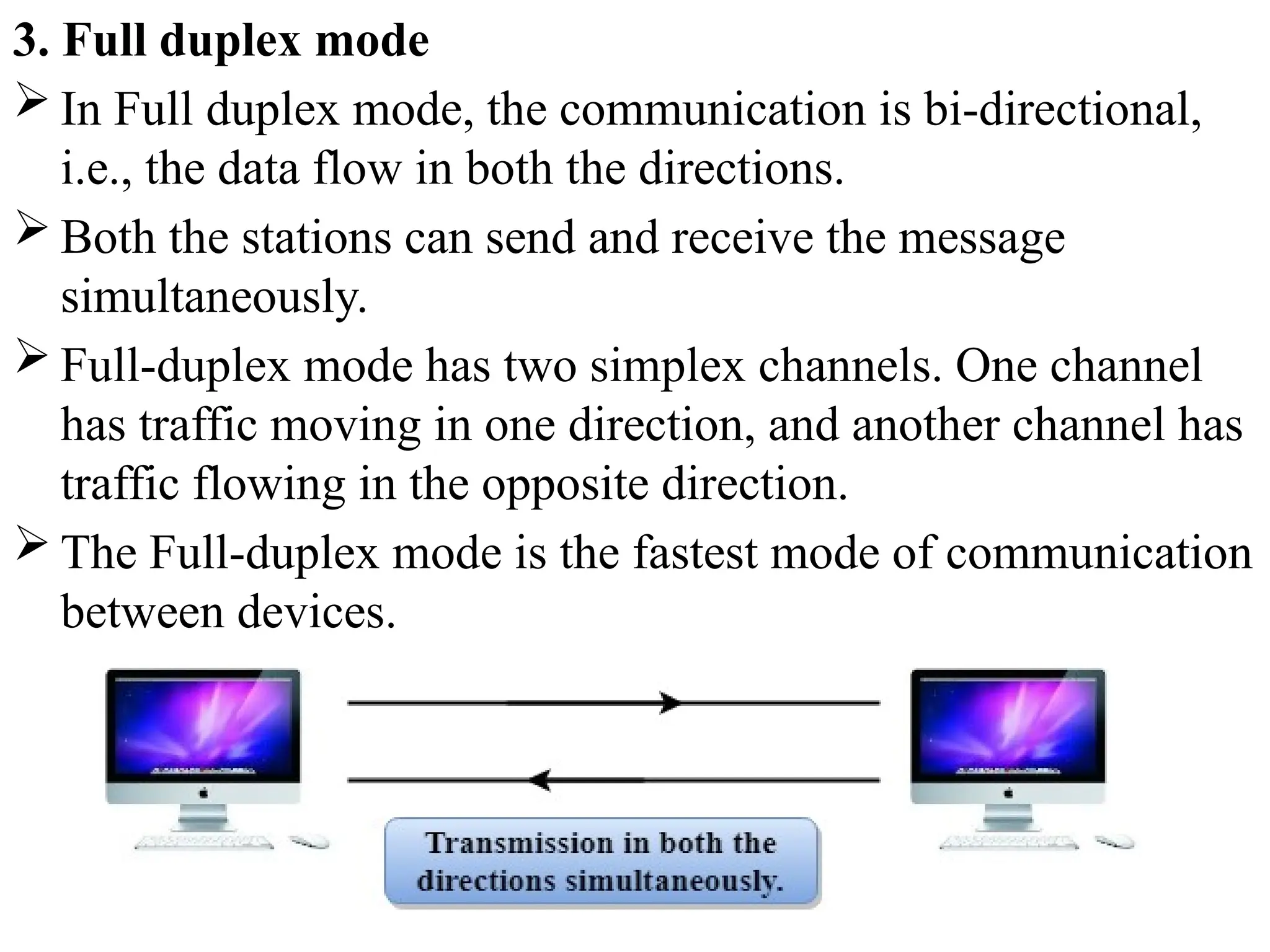
3. Full duplexmode
In Full duplex mode, the communication is bi-directional,
i.e., the data flow in both the directions.
Both the stations can send and receive the message
simultaneously.
Full-duplex mode has two simplex channels. One channel
has traffic moving in one direction, and another channel has
traffic flowing in the opposite direction.
The Full-duplex mode is the fastest mode of communication
between devices.
18.
The mostcommon example of the full-duplex mode is a
telephone network. When two people are communicating
with each other by a telephone line, both can talk and listen
at the same time.
Advantage of Full-duplex mode:
Both the stations can send and receive the data at the same
time.
Disadvantage of Full-duplex mode:
If there is no dedicated path exists between the devices, then
the capacity of the communication channel is divided into
two parts.
19.
Computer Network Architecture
ComputerNetwork Architecture is defined as the
physical and logical design of the software,
hardware, protocols, and media of the transmission
of data. Simply we can say that how computers are
organized and how tasks are allocated to the
computer.
The two types of network architectures are used:
1. Peer-To-Peer network
2. Client/Server network
20.
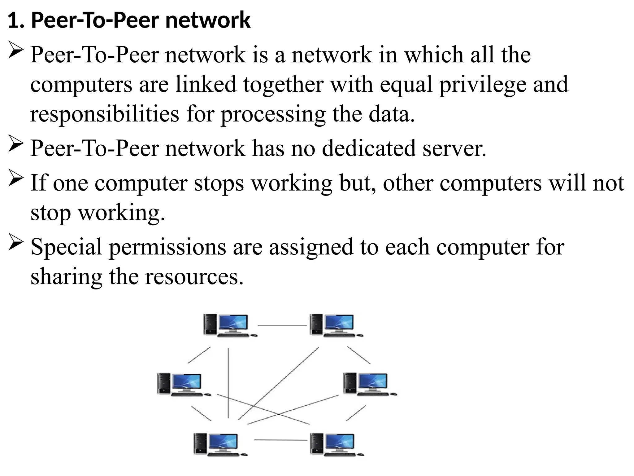
1. Peer-To-Peer network
Peer-To-Peer network is a network in which all the
computers are linked together with equal privilege and
responsibilities for processing the data.
Peer-To-Peer network has no dedicated server.
If one computer stops working but, other computers will not
stop working.
Special permissions are assigned to each computer for
sharing the resources.
21.
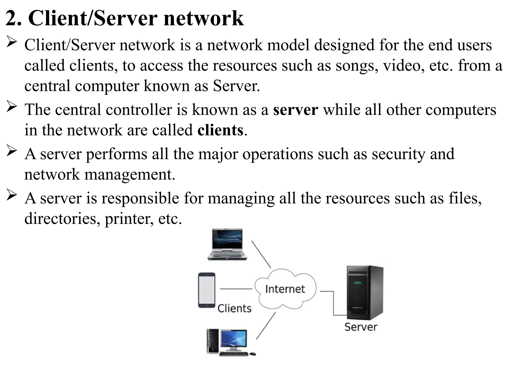
2. Client/Server network
Client/Server network is a network model designed for the end users
called clients, to access the resources such as songs, video, etc. from a
central computer known as Server.
The central controller is known as a server while all other computers
in the network are called clients.
A server performs all the major operations such as security and
network management.
A server is responsible for managing all the resources such as files,
directories, printer, etc.
22.
Advantages Of Client/Servernetwork:
A Client/Server network contains the centralized system. Therefore we
can back up the data easily.
A Client/Server network has a dedicated server that improves the
overall performance of the whole system.
Security is better in Client/Server network as a single server
administers the shared resources.
It also increases the speed of the sharing resources.
Disadvantages Of Client/Server network:
Client/Server network is expensive as it requires the server with large
memory.
A server has a Network Operating System(NOS) to provide the
resources to the clients, but the cost of NOS is very high.
It requires a dedicated network administrator to manage all the
resources.
23.
Network Hardware Components
Different components are used to create a computer network. The
main components used to form a computer network are Hardware
components and Software components.
Hardware components such as Computer, Transmission devices such
as NIC, hub, switch, bridge, gateway, repeater, and router, Channels
such as wires, microwaves, radio waves, and satellite, and Software
such as NOS(network operating system) and communication
Protocols are the required components to create a network.
Network hardware components are required for communication and
interaction between devices on a computer network.
Some important network components
are NIC, switch, cables, hub, router, repeaters, gateway, bridge
and modem. Depending on the type of network that we need to
install, some network components can also be removed.
For example, the wireless network does not require a cable.
24.
1. NIC(Network interfacecard )
A network interface card (NIC) is a hardware component
without which a computer cannot be connected over a
network.
It is a circuit board installed in a computer that provides a
dedicated network connection to the computer. It is also
called network interface controller, network adapter or
LAN adapter.
Purpose
NIC allows both wired and wireless communications.
NIC allows communications between computers
connected via local area network (LAN) as well as
communications over large-scale network through
Internet Protocol (IP) address.
25.
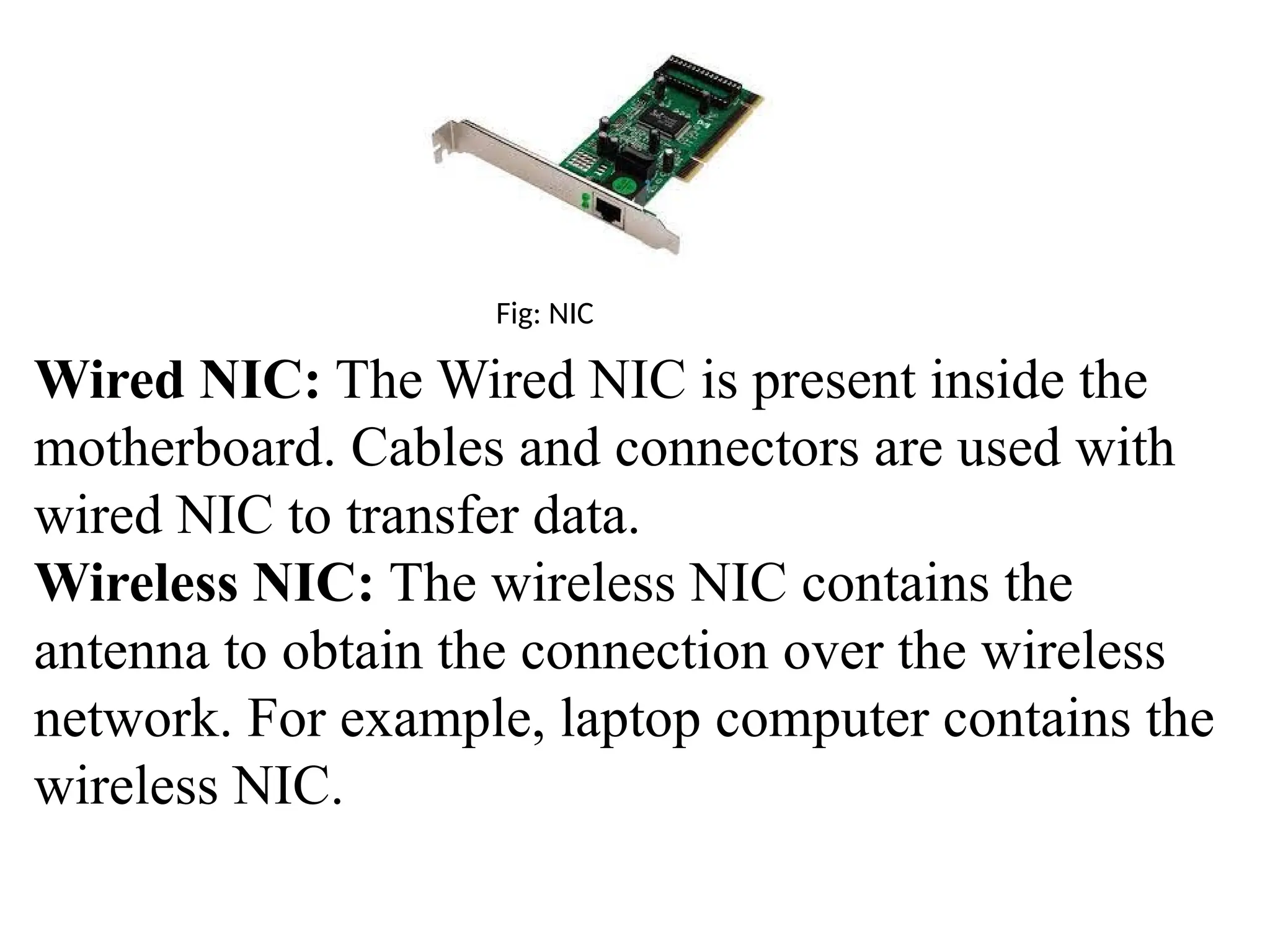
Fig: NIC
Wired NIC:The Wired NIC is present inside the
motherboard. Cables and connectors are used with
wired NIC to transfer data.
Wireless NIC: The wireless NIC contains the
antenna to obtain the connection over the wireless
network. For example, laptop computer contains the
wireless NIC.
26.
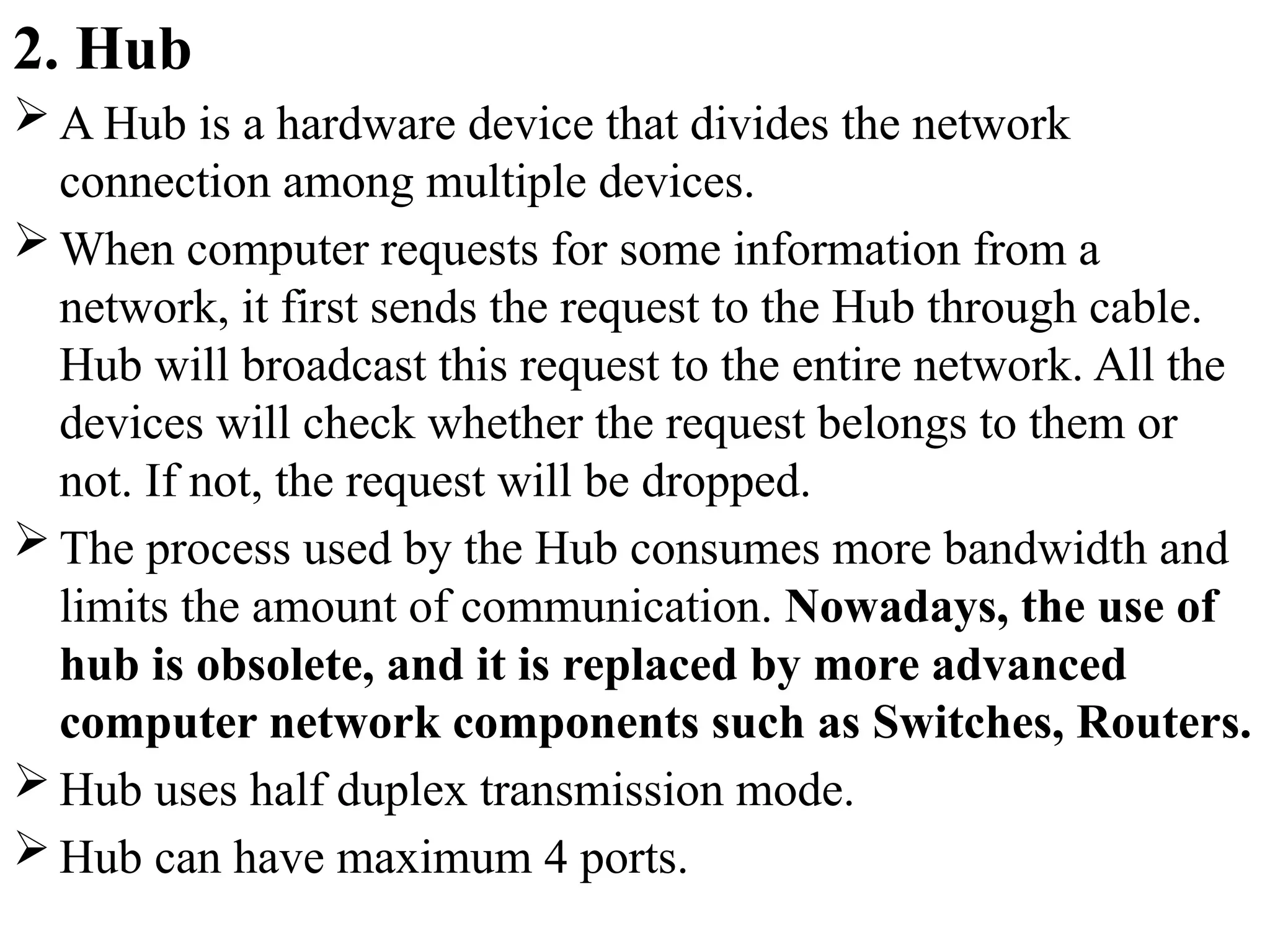
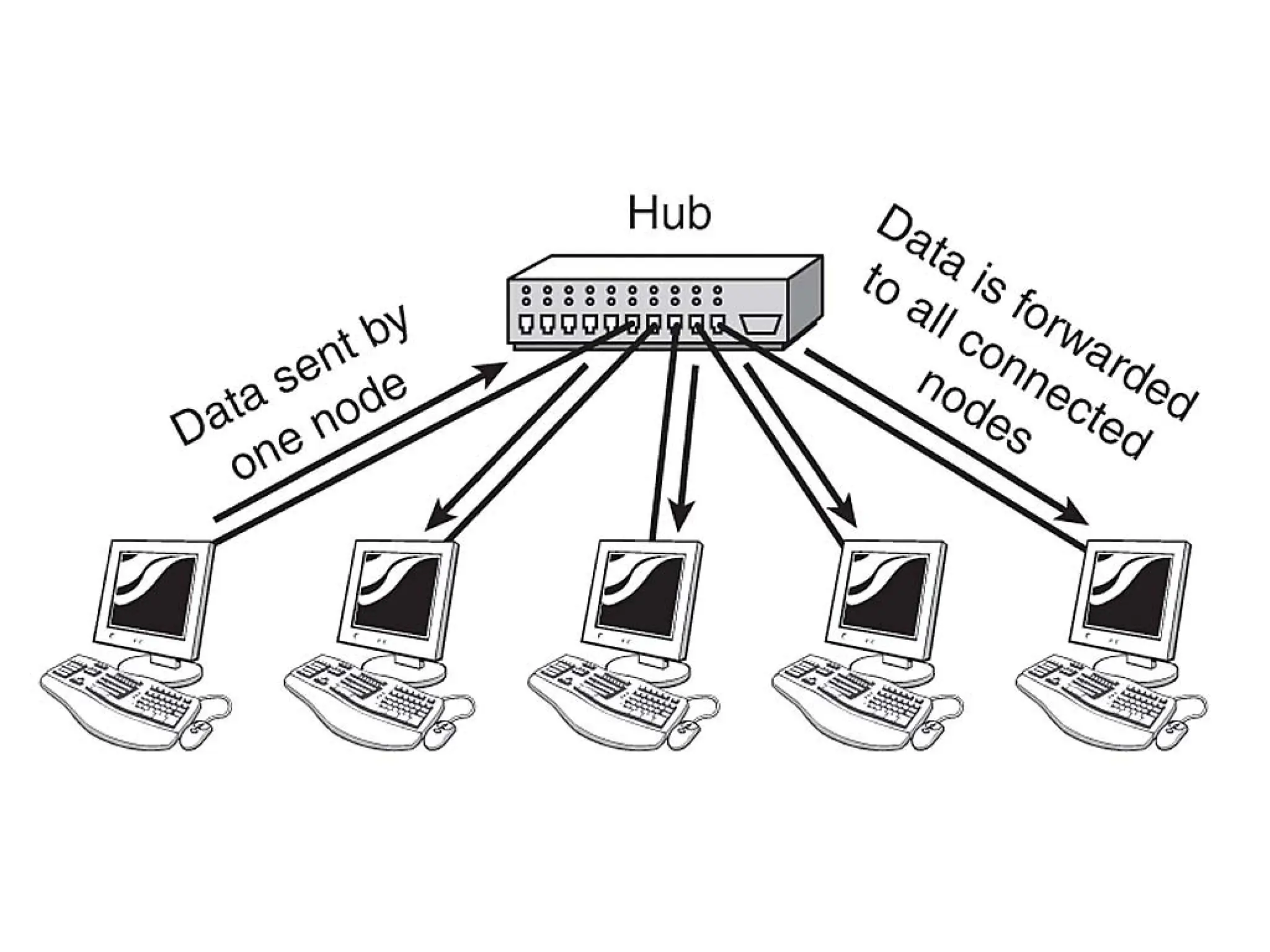
2. Hub
AHub is a hardware device that divides the network
connection among multiple devices.
When computer requests for some information from a
network, it first sends the request to the Hub through cable.
Hub will broadcast this request to the entire network. All the
devices will check whether the request belongs to them or
not. If not, the request will be dropped.
The process used by the Hub consumes more bandwidth and
limits the amount of communication. Nowadays, the use of
hub is obsolete, and it is replaced by more advanced
computer network components such as Switches, Routers.
Hub uses half duplex transmission mode.
Hub can have maximum 4 ports.
28.
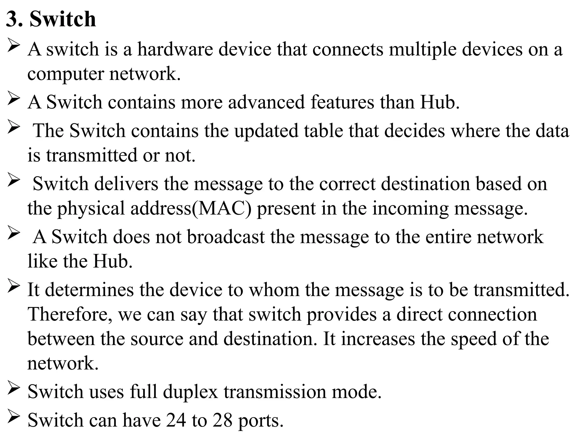
3. Switch
Aswitch is a hardware device that connects multiple devices on a
computer network.
A Switch contains more advanced features than Hub.
The Switch contains the updated table that decides where the data
is transmitted or not.
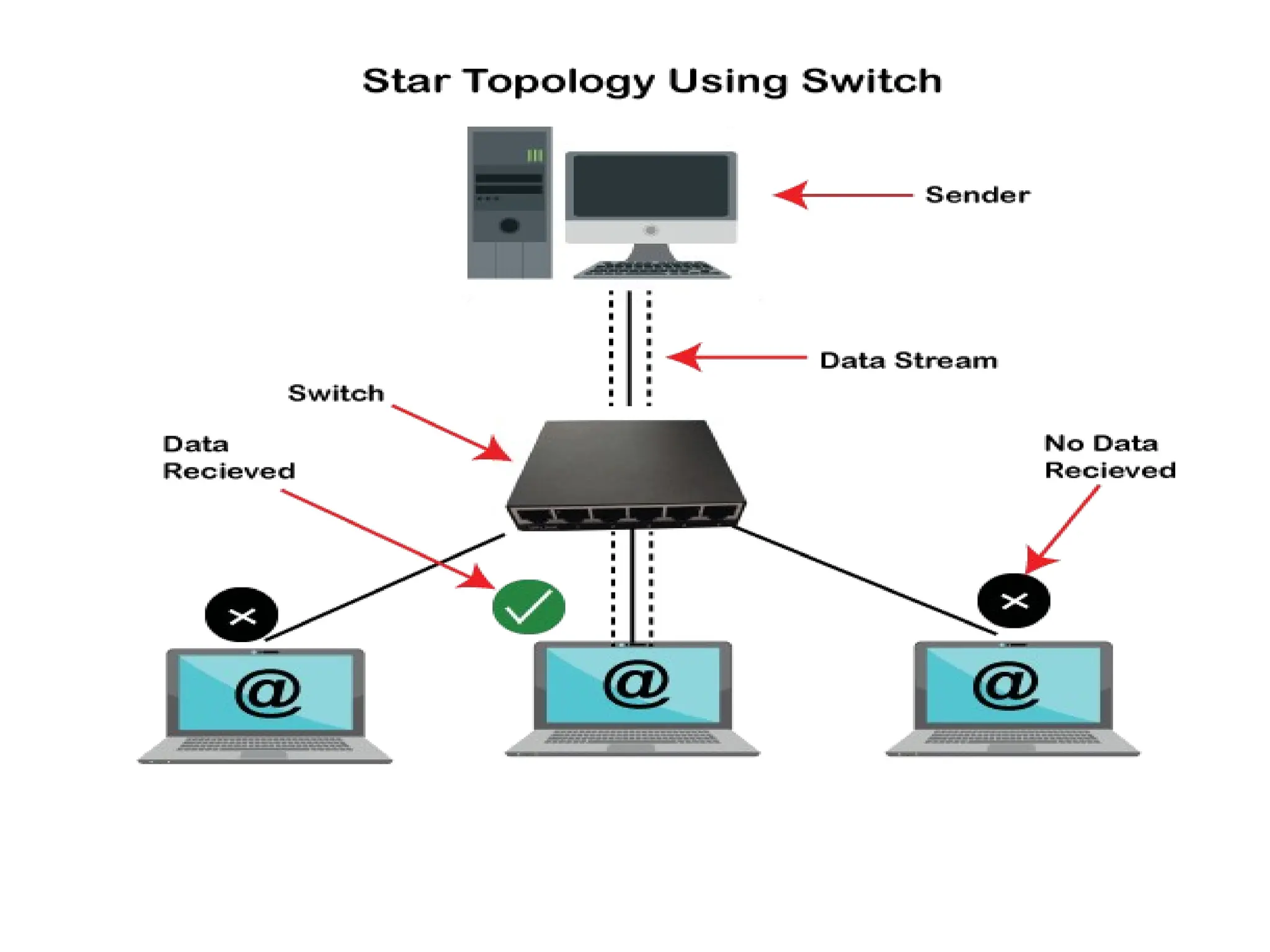
Switch delivers the message to the correct destination based on
the physical address(MAC) present in the incoming message.
A Switch does not broadcast the message to the entire network
like the Hub.
It determines the device to whom the message is to be transmitted.
Therefore, we can say that switch provides a direct connection
between the source and destination. It increases the speed of the
network.
Switch uses full duplex transmission mode.
Switch can have 24 to 28 ports.
30.
4. Router
Arouter is a hardware device which is used to connect a
LAN with an internet connection. It is used to receive,
analyze and forward the incoming packets to another
network.
A router works in a Layer 3 (Network layer) of the OSI
Reference model.
A router forwards the packet based on the information
available in the routing table.
It determines the best path from the available paths for the
transmission of the packet.
31.
Why Routers?
A routeris more capable as compared to other
network devices, such as a hub, switch, etc., as these
devices are only able to execute the basic functions of
the network.
For example, a hub is a basic networking device that
is mainly used to forward the data between connected
devices, but it cannot analyze or change anything with
the transferring data.
32.
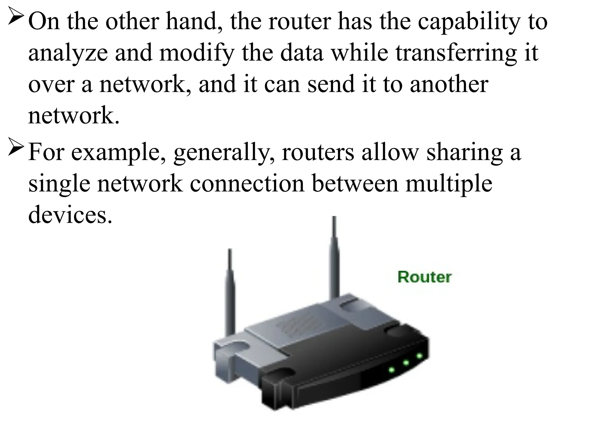
On the otherhand, the router has the capability to
analyze and modify the data while transferring it
over a network, and it can send it to another
network.
For example, generally, routers allow sharing a
single network connection between multiple
devices.
33.
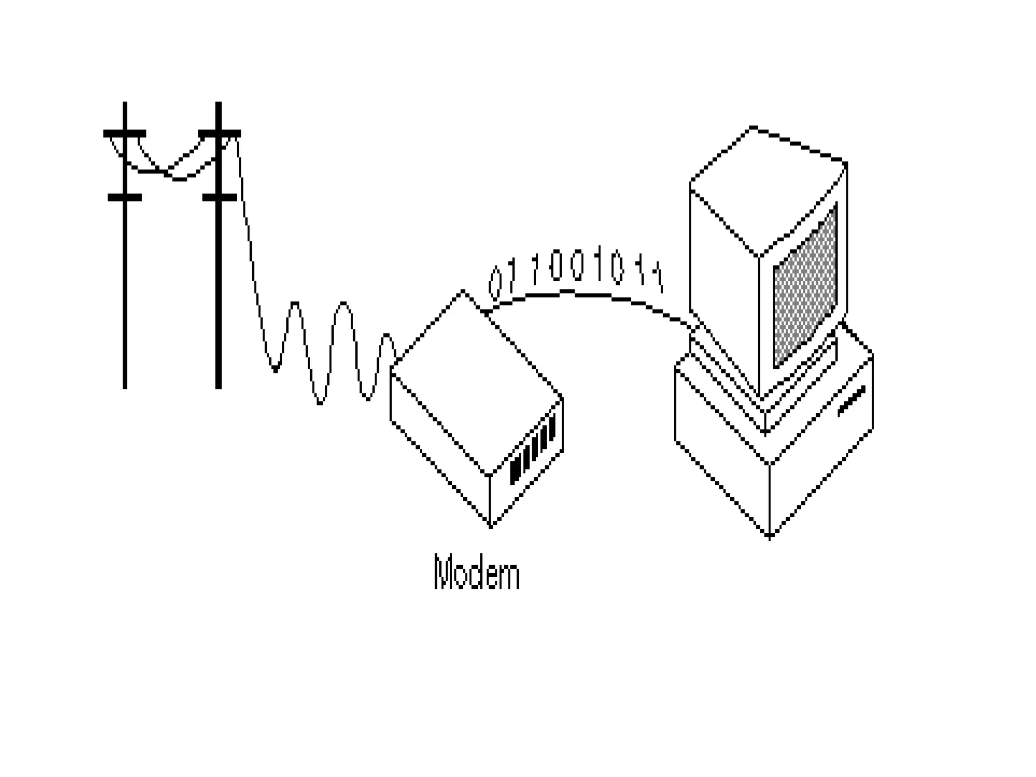
5. Modem
It standsfor Modulator/Demodulator. It converts the
digital data into an analog signal over the telephone
lines.
A modem is a hardware device that allows the computer to
connect to the internet over the existing telephone line.
A modem is not integrated with the motherboard rather
than it is installed on the PCI slot found on the
motherboard.
Based on the differences in speed and transmission rate, a
modem can be classified in the following categories:
a. Standard PC modem or Dial-up modem
b. Cellular Modem
c. Cable modem
35.
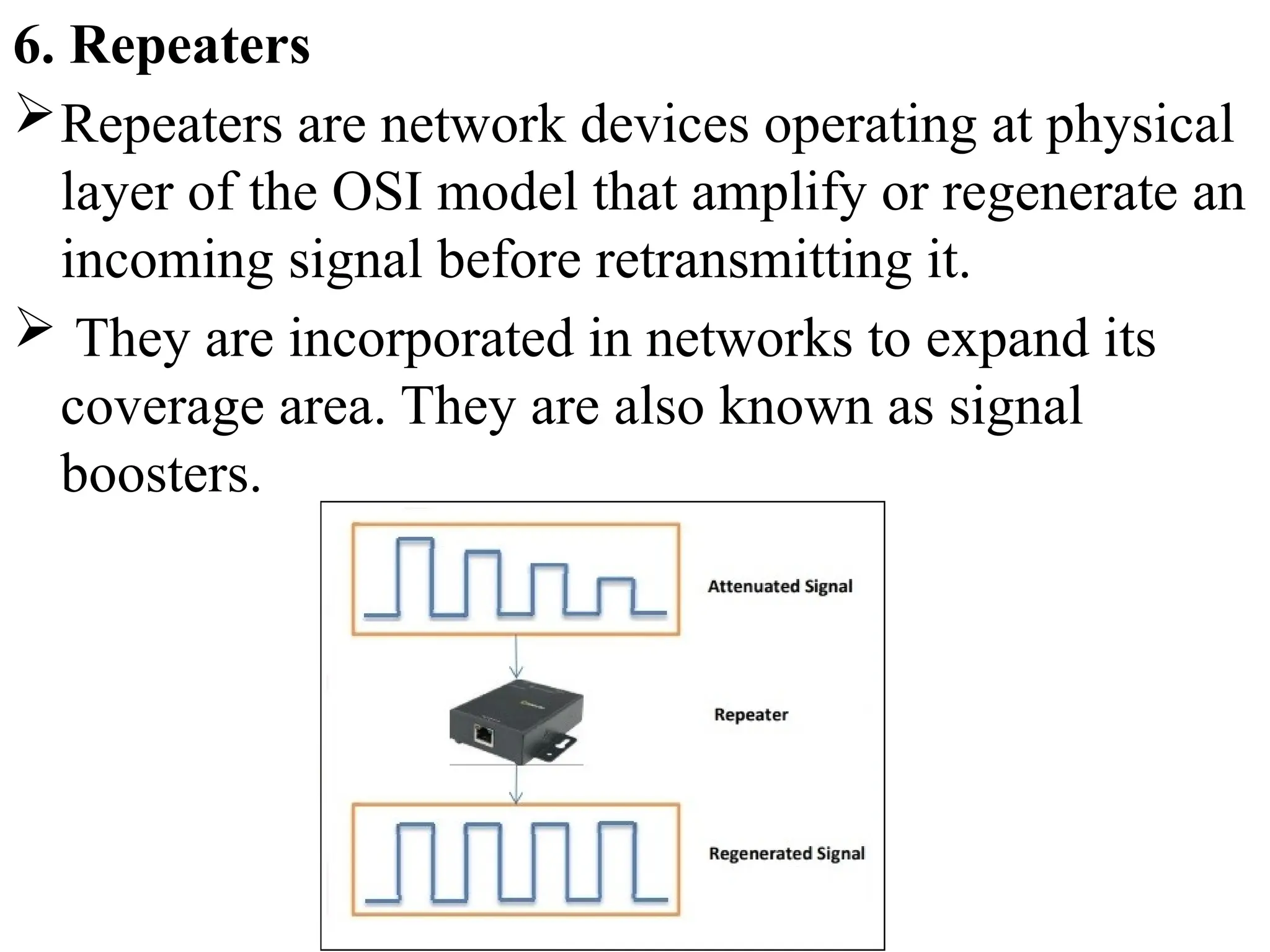
6. Repeaters
Repeaters arenetwork devices operating at physical
layer of the OSI model that amplify or regenerate an
incoming signal before retransmitting it.
They are incorporated in networks to expand its
coverage area. They are also known as signal
boosters.
36.
Ex: When thesignals travels in the network, after
travelling some distance the intensity of the signal
becomes low. In order to regenerate the weak
signal we should use repeater device.
It is cheaper than other network devices
Repeaters has the ability to extend the length of
signal.
It maintain the signal performance.
Repeater can’t reduce the network traffic
Repeaters also unable to connect dis-similar type
of network.
37.
7. Cables andConnectors
Cable is a transmission media used for transmitting a signal.
There are three types of cables used in transmission:
a. Twisted pair cable
b. Coaxial cable
c. Fibre-optic cable
a. Twisted pair cable: It is a high-speed cable that transmits
the data over 1Gbps or more.
b. Coaxial cable: Coaxial cable resembles like a TV
installation cable. Coaxial cable is more expensive than
twisted pair cable, but it provides the high data
transmission speed.
38.
c. Fibre opticcable: Fibre optic cable is a high-speed
cable that transmits the data using light beams.
It provides high data transmission speed as
compared to other cables. It is more expensive as
compared to other cables, so it is installed at the
government level.
39.
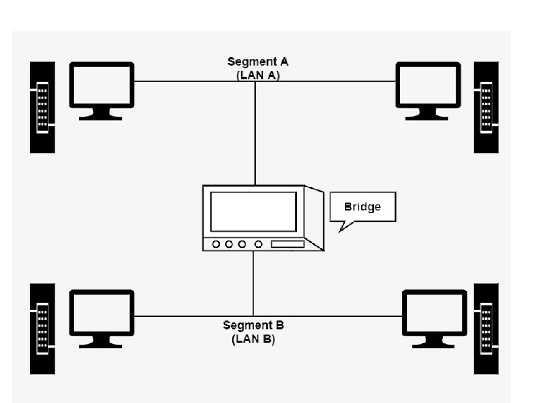
8. Bridge
A bridgeis a network device that connects multiple LANs
(local area networks) together to form a larger LAN. The
process of aggregating networks is called network bridging.
A bridge connects the different components so that they
appear as parts of a single network.
A bridge maintains a MAC address of various devices
attached to it.
When a packet enters a bridge, it checks the address
contained in the packet and compares it with a table of all
the devices on both LAN’s.
Bridge working on the same transmission protocol.
Bridges operate at the data link layer and physical layer of
the OSI model.
40.
By using bridgedevice we can extends network.
Collision can be reduced easily.
It doesn’t establish a connection between two
different networks.
Once it broadcast the packets then it is incapable to
stop the packets.
It is more expensive.
The transmission rate of data is slower than repeater.
42.
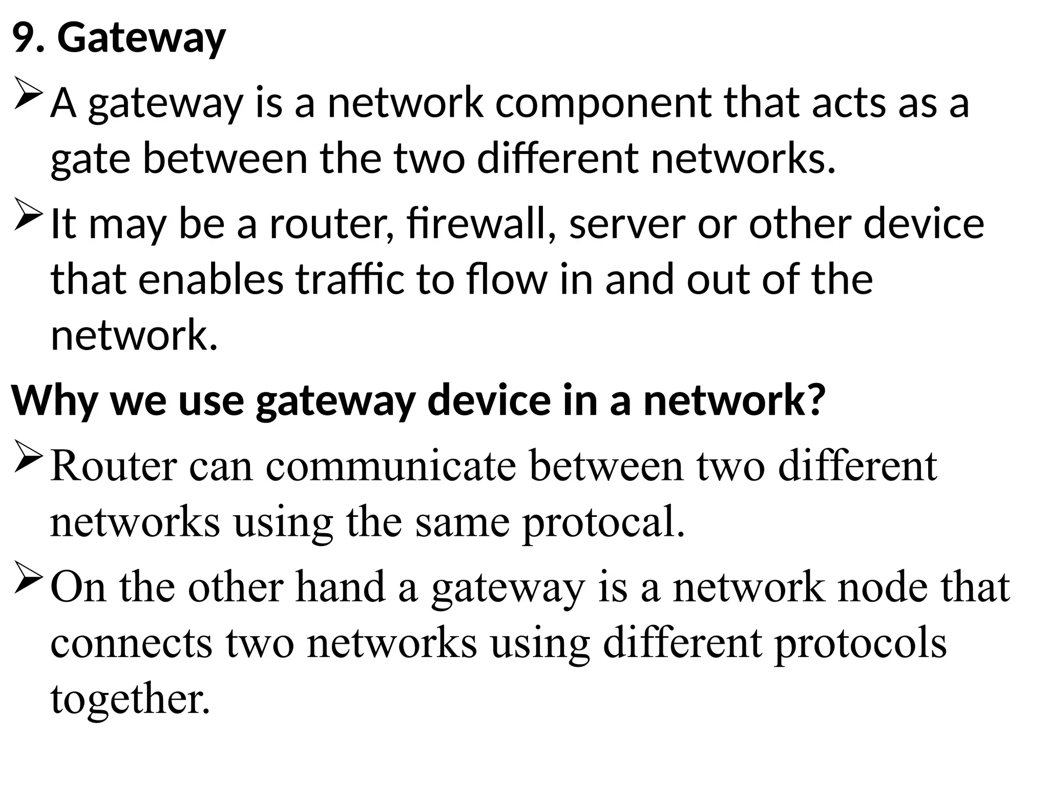
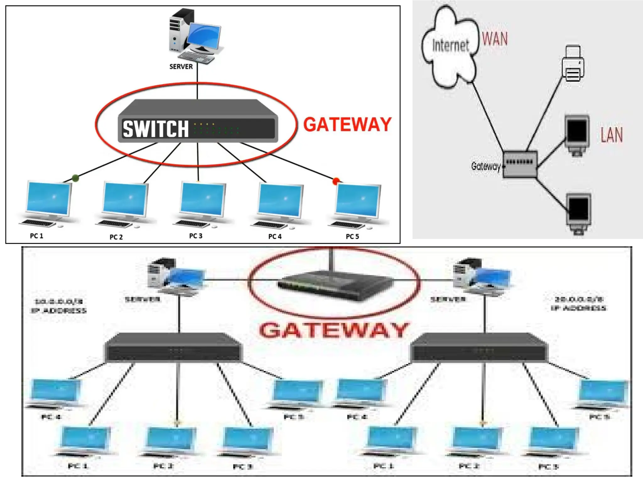
9. Gateway
A gatewayis a network component that acts as a
gate between the two different networks.
It may be a router, firewall, server or other device
that enables traffic to flow in and out of the
network.
Why we use gateway device in a network?
Router can communicate between two different
networks using the same protocal.
On the other hand a gateway is a network node that
connects two networks using different protocols
together.
43.
Gateway is alsocalled protocal converter.
It allow us to send and receive data through the
internet even it is LAN network.
Gateway operates all 7 layers of OSI model.
We can’t access the internet with out a gateway.
It provide same security.
It is more expensive.
Data transimission rate is slower.
Difficult to maintain as well as very complex.
45.
Computer Network Types
A computer network is a group of computers linked to each
other that enables the computer to communicate with
another computer and share their resources, data, and
applications.
A computer network can be categorized by their size.
A computer network is mainly of four types:
1. LAN(Local Area Network)
2. PAN(Personal Area Network)
3. MAN(Metropolitan Area Network)
4. WAN(Wide Area Network)
46.
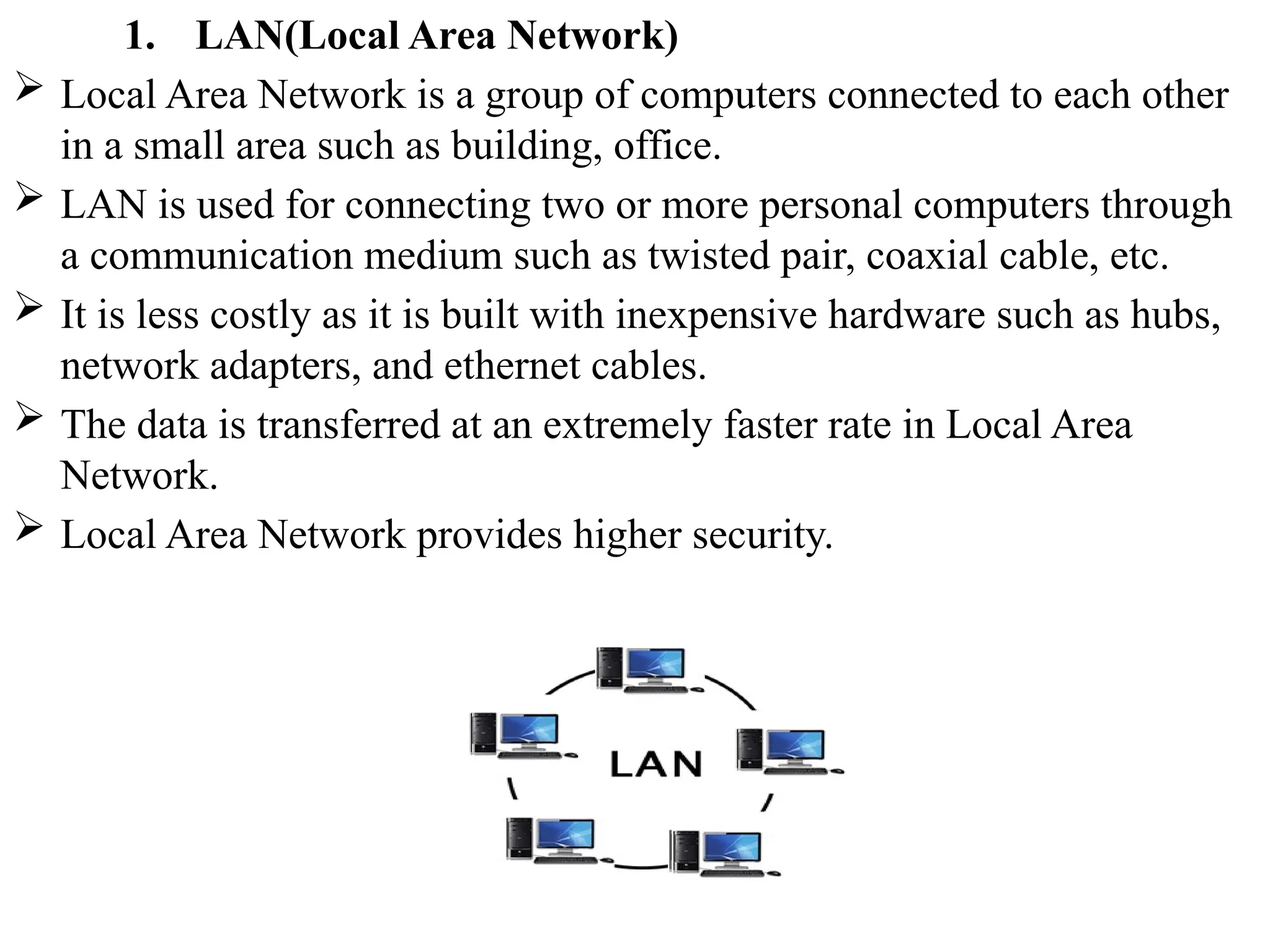
1. LAN(Local AreaNetwork)
Local Area Network is a group of computers connected to each other
in a small area such as building, office.
LAN is used for connecting two or more personal computers through
a communication medium such as twisted pair, coaxial cable, etc.
It is less costly as it is built with inexpensive hardware such as hubs,
network adapters, and ethernet cables.
The data is transferred at an extremely faster rate in Local Area
Network.
Local Area Network provides higher security.
47.
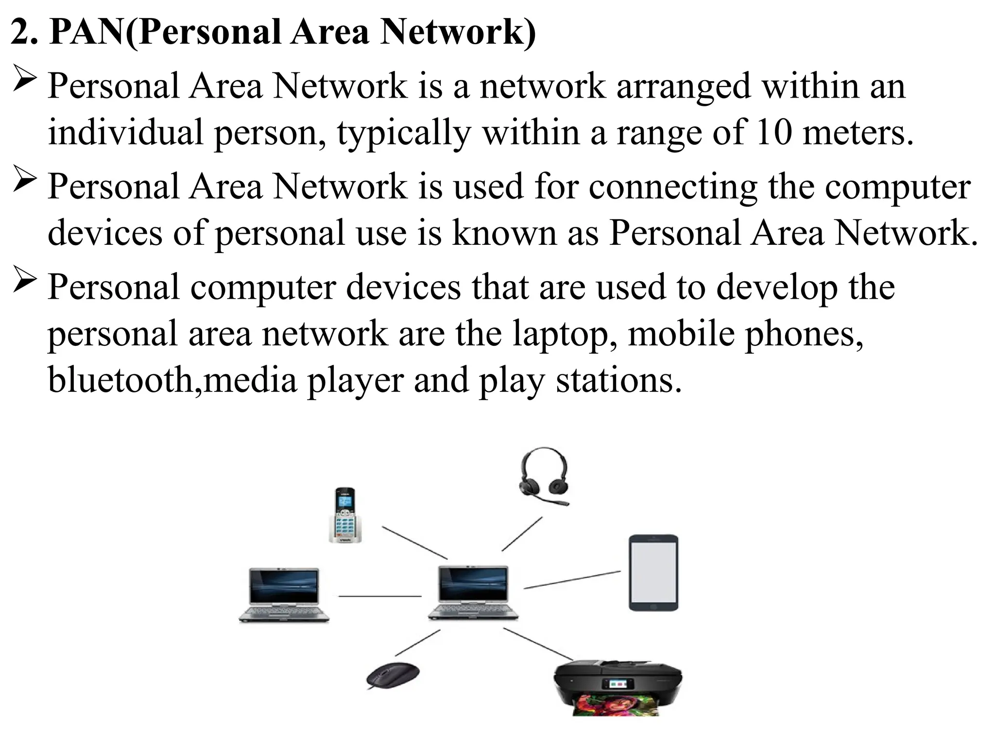
2. PAN(Personal AreaNetwork)
Personal Area Network is a network arranged within an
individual person, typically within a range of 10 meters.
Personal Area Network is used for connecting the computer
devices of personal use is known as Personal Area Network.
Personal computer devices that are used to develop the
personal area network are the laptop, mobile phones,
bluetooth,media player and play stations.
48.
There are twotypes of Personal Area Network:
1. Wired Personal Area Network Ex: USB
2. Wireless Personal Area Network Ex: bluetooth,wifi
3. MAN(Metropolitan Area Network)
A metropolitan area network is a network that covers a larger
geographic area by interconnecting a different LAN to form a larger
network.
Government agencies use MAN to connect to the citizens and
private industries.
In MAN, various LANs are connected to each other through a
telephone exchange line.
It has a higher range than Local Area Network(LAN).
49.
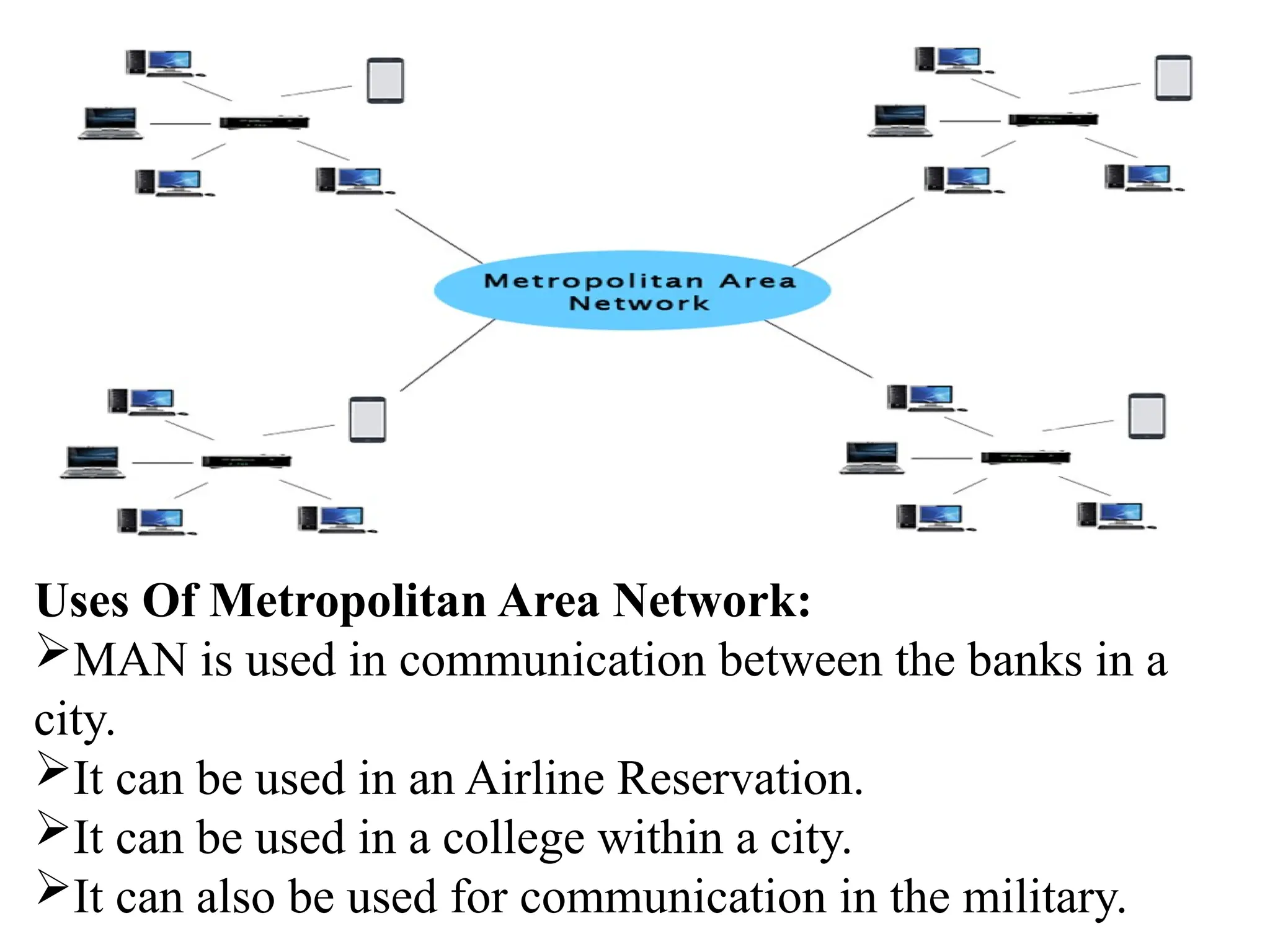
Uses Of MetropolitanArea Network:
MAN is used in communication between the banks in a
city.
It can be used in an Airline Reservation.
It can be used in a college within a city.
It can also be used for communication in the military.
50.
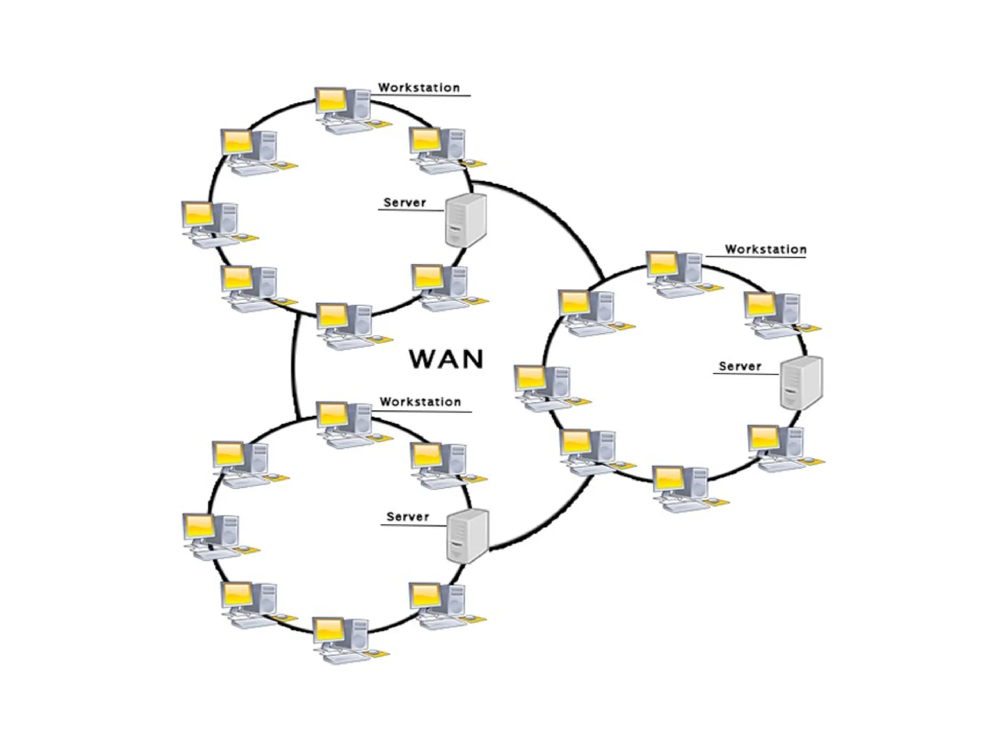
4. WAN(Wide AreaNetwork)
A Wide Area Network is a network that extends over a large
geographical area such as states or countries.
A Wide Area Network is quite bigger network than the
LAN.
A Wide Area Network is not limited to a single location, but
it spans over a large geographical area through a telephone
line, fibre optic cable or satellite links.
The internet is one of the biggest WAN in the world.
A Wide Area Network is widely used in the field of
Business, government, and education.
52.
Examples Of WideArea Network:
Mobile Broadband: A 4G network is widely used across a
region or country.
Last mile: A telecom company is used to provide the
internet services to the customers in hundreds of cities by
connecting their home with fiber.
Advantages Of Wide Area Network
Global business: We can do the business over the internet
globally.
High bandwidth: If we use the leased lines for our
company then this gives the high bandwidth. The high
bandwidth increases the data transfer rate which in turn
increases the productivity of our company.
53.
Centralized data:In case of WAN network, data is
centralized. Therefore, we do not need to buy the emails,
files or back up servers.
Get updated files: Software companies work on the live
server. Therefore, the programmers get the updated files
within seconds.
Exchange messages: In a WAN network, messages are
transmitted fast. The web application like Facebook,
Whatsapp, Skype allows you to communicate with friends.
54.
Disadvantages of WideArea Network
Security issue: A WAN network has more security issues as
compared to LAN and MAN network as all the technologies
are combined together that creates the security problem.
Needs Firewall & antivirus software: The data is
transferred on the internet which can be changed or hacked
by the hackers, so the firewall needs to be used. Some
people can inject the virus in our system so antivirus is
needed to protect from such a virus.
High Setup cost: An installation cost of the WAN network
is high as it involves the purchasing of routers, switches.
Troubleshooting problems: It covers a large area so fixing
the problem is difficult.
55.
Network Topology
Topologydefines the structure of the network of how all the
components are interconnected to each other. There are two
types of topology: physical and logical topology.
Physical topology is the geometric representation of all the
nodes in a network.
Types of Network topology
1. Bus Topology
2. Ring Topology
3. Star Topology
4. Mesh Topology
5. Tree Topology
6. Hybrid Topology
56.
1. Bus Topology
Abus topology (or) a line topology is a network
setup in which each computer and network device
are connected to a single cable or backbone cable.
Each node is either connected to the backbone cable
by drop cable or directly connected to the backbone
cable.
When a node wants to send a message over the
network, it puts a message over the network. All the
stations available in the network will receive the
message whether it has been addressed or not.
57.
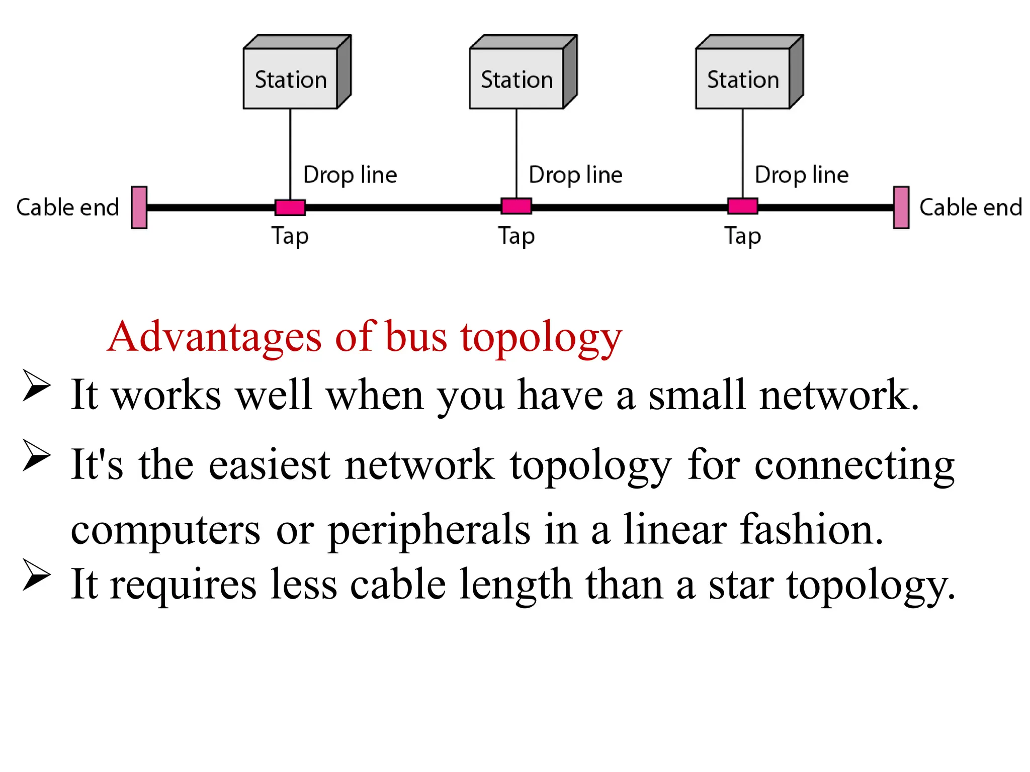
Advantages of bustopology
It works well when you have a small network.
It's the easiest network topology for connecting
computers or peripherals in a linear fashion.
It requires less cable length than a star topology.
58.
Disadvantages of bustopology
It can be difficult to identify the problems if the
whole network goes down.
It can be hard to troubleshoot individual device
issues.
Bus topology is not great for large networks.
Terminators are required for both ends of the
main cable.
Additional devices slow the network down.
If a main cable is damaged, the network fails .
59.
2. Ring Topology
Ring topology is like a bus topology, but with connected
ends.
The node that receives the message from the previous
computer will retransmit to the next node.
The data flows in a single loop continuously known as an
endless loop.
It has no terminated ends, i.e., each node is connected to
other node and having no termination point.
60.
The data ina ring topology flow in a clockwise direction.
Ring topologies may be used in either local area networks
(LANs) or wide area networks (WANs).
The data flows in one direction, i.e.., it is unidirectional,
but it can be made bidirectional by having 2 connections
between each Network Node, it is called Dual Ring
Topology. In-Ring Topology, the Token Ring Passing
protocol is used by the workstations to transmit the data.
61.
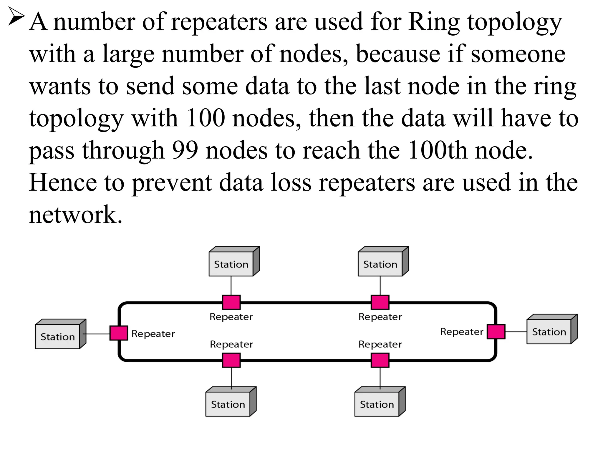
A number ofrepeaters are used for Ring topology
with a large number of nodes, because if someone
wants to send some data to the last node in the ring
topology with 100 nodes, then the data will have to
pass through 99 nodes to reach the 100th node.
Hence to prevent data loss repeaters are used in the
network.
62.
The mostcommon access method of ring topology is token
passing.
Token passing : It is network access method in which
token is passed from one node to another node.
Token : It is a frame that circulates around network.
Working of Token passing
A token moves around the network, and it is passed from
computer to computer until it reaches the destination.
The sender modifies the token by putting the address along
with the data.
The data is passed from one device to another device until
the destination address matches. Once the token received
by the destination device, then it sends the
acknowledgment to the sender.
In a ring topology, a token is used as a carrier.
63.
Advantages of Ringtopology:
The data transmission is high-speed.
The possibility of collision is minimum in this type of
topology.
Cheap to install and expand.
It is less costly than a star topology.
Disadvantages of Ring topology
The failure of a single node in the network can cause the entire
network to fail.
Troubleshooting is difficult in this topology.
The addition of stations in between or removal of stations can
disturb the whole topology.
Less secure.
64.
3. Star Topology
Startopology is an arrangement of the network in which
every node is connected to the central hub, switch or a
central computer.
The central computer is known as a server, and the
peripheral devices attached to the server are known
as clients.
Coaxial cable or RJ-45 cables are used to connect the
computers.
65.
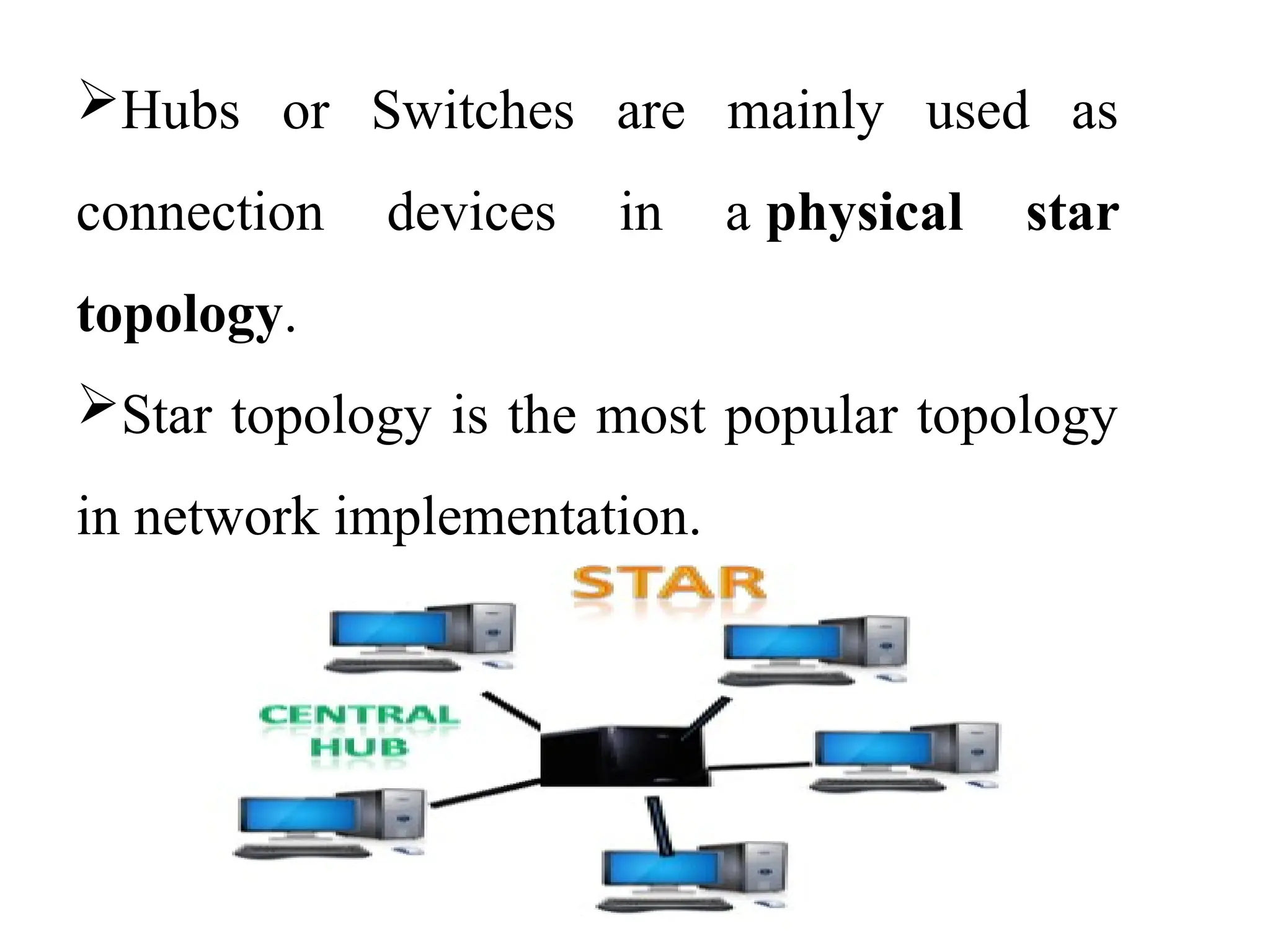
Hubs or Switchesare mainly used as
connection devices in a physical star
topology.
Star topology is the most popular topology
in network implementation.
66.
Advantages of Startopology
Efficient troubleshooting: Troubleshooting is quite efficient in
a star topology. In a star topology, all the stations are connected
to the centralized network. Therefore, the network administrator
has to go to the single station to troubleshoot the problem.
Easy to add another computer to the network.
If one computer on the network fails, the rest of the network
continues to function normally.
The star topology is used in local-area networks (LANs),
High-speed LANs often use a star topology with a central hub.
67.
Disadvantages of Startopology
A Central point of failure: If the central hub or
switch goes down, then all the connected nodes will
not be able to communicate with each other.
The cost of installation is high.
Performance is based on the hub(central device)
that’s it depends on its capacity.
68.
4. Mesh Topology
Meshtechnology is an arrangement of the network in
which computers are interconnected with each other
through various redundant(extra) connections.
There are multiple paths from one computer to another
computer.
It does not contain the switch, hub or any central
computer which acts as a central point of communication.
The Internet is an example of the mesh topology.
69.
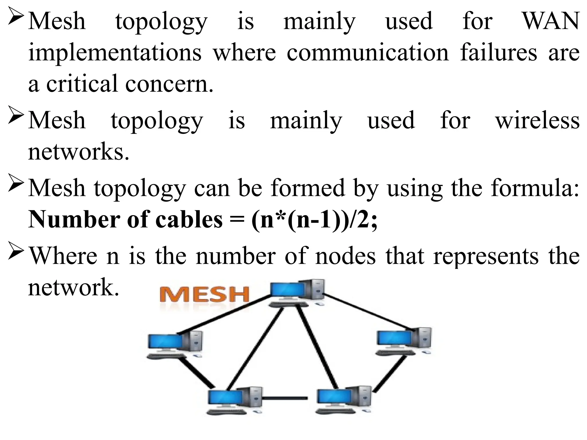
Mesh topology ismainly used for WAN
implementations where communication failures are
a critical concern.
Mesh topology is mainly used for wireless
networks.
Mesh topology can be formed by using the formula:
Number of cables = (n*(n-1))/2;
Where n is the number of nodes that represents the
network.
70.
Mesh topology isdivided into two categories:
• Full Mesh Topology: In a full mesh topology, each computer
is connected to all the computers available in the network.
• Partial Mesh Topology: In a partial mesh topology, not all
but certain computers are connected to those computers with
which they communicate frequently.
Advantages of Mesh topology:
Reliable: The mesh topology networks are very reliable as if
any link breakdown will not affect the communication
between connected computers.
Fast Communication: Communication is very fast between
the nodes.
Easier Reconfiguration: Adding new devices would not
disrupt the communication between other devices.
71.
Disadvantages of Meshtopology
Cost: A mesh topology contains a large number of
connected devices such as a router and more transmission
media than other topologies. So, cost is more.
Management: Mesh topology networks are very large and
very difficult to maintain and manage. If the network is not
monitored carefully, then the communication link failure
goes undetected.
Efficiency: In this topology, redundant connections are high
that reduces the efficiency of the network.
72.
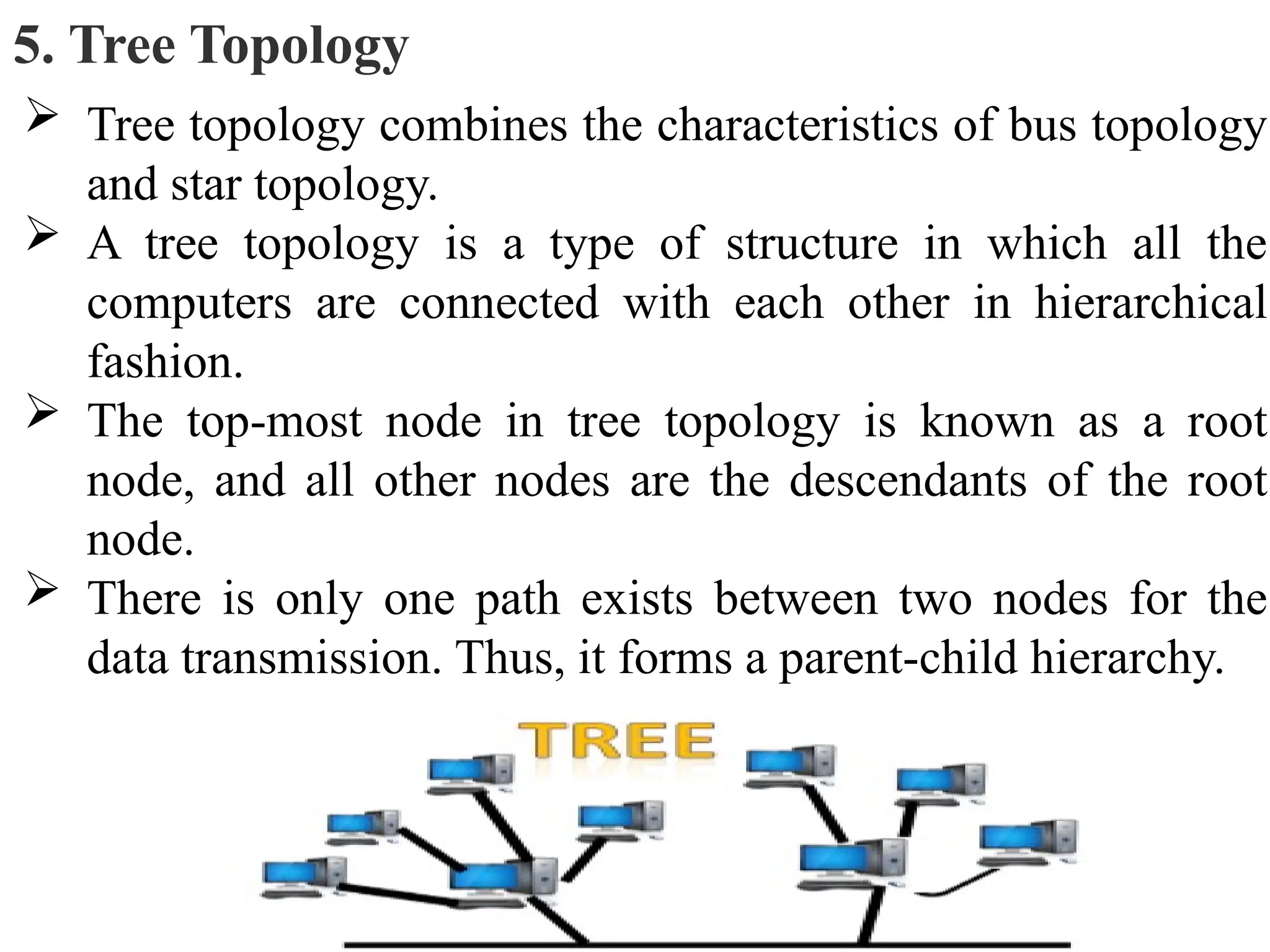
5. Tree Topology
Tree topology combines the characteristics of bus topology
and star topology.
A tree topology is a type of structure in which all the
computers are connected with each other in hierarchical
fashion.
The top-most node in tree topology is known as a root
node, and all other nodes are the descendants of the root
node.
There is only one path exists between two nodes for the
data transmission. Thus, it forms a parent-child hierarchy.
73.
Advantages of Treetopology
Support for broadband transmission: Tree topology is
mainly used to provide broadband transmission, i.e., signals
are sent over long distances without being attenuated.
Easily expandable: We can add the new device to the
existing network. Therefore, we can say that tree topology is
easily expandable.
Easily manageable: In tree topology, the whole network is
divided into segments known as star networks which can be
easily managed and maintained.
Error detection: Error detection and error correction are
very easy in a tree topology.
Limited failure: The breakdown in one station does not
affect the entire network.
74.
Disadvantages of Treetopology
Difficult troubleshooting: If any fault occurs in the node,
then it becomes difficult to troubleshoot the problem.
High cost: Devices required for broadband transmission are
very costly.
Failure: A tree topology mainly relies on main bus cable and
failure in main bus cable will damage the overall network.
Reconfiguration difficult: If new devices are added, then it
becomes difficult to reconfigure.
75.
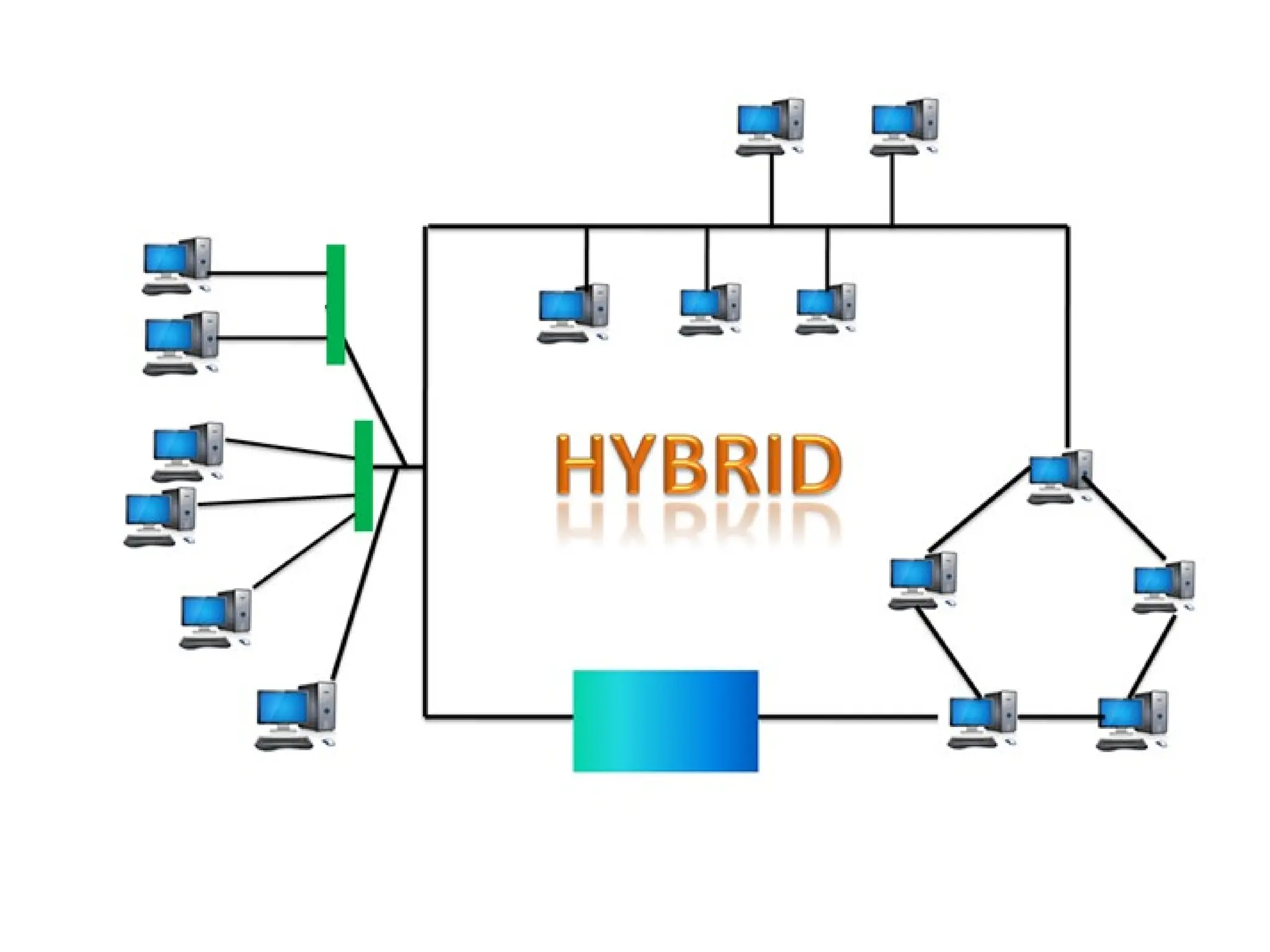
6. Hybrid Topology
The combination of various different topologies is known
as Hybrid topology.
A Hybrid topology is a connection between different links and
nodes to transfer the data.
When two or more different topologies are combined together is
termed as Hybrid topology and if similar topologies are
connected with each other will not result in Hybrid topology. For
example, if there exist a ring topology in one branch of ICICI
bank and bus topology in another branch of ICICI bank,
connecting these two topologies will result in Hybrid topology.
77.
Advantages of HybridTopology
Reliable: If a fault occurs in any part of the network will not
affect the functioning of the rest of the network.
Scalable: Size of the network can be easily expanded by adding
new devices without affecting the functionality of the existing
network.
Flexible: This topology is very flexible as it can be designed
according to the requirements of the organization.
Effective: Hybrid topology is very effective as it can be designed
in such a way that the strength of the network is maximized and
weakness of the network is minimized.
78.
Disadvantages of Hybridtopology
Complex design: The major drawback of the Hybrid
topology is the design of the Hybrid network. It is very
difficult to design the architecture of the Hybrid network.
Costly Hub: The Hubs used in the Hybrid topology are
very expensive as these hubs are different from usual Hubs
used in other topologies.
Costly infrastructure: The infrastructure cost is very high
as a hybrid network requires a lot of cabling, network
devices, etc.
79.
NETWORK SOFTWARE
Networksoftware is a set of tools (or) set of
rules/protocols that helps computers to share
information with each other or allows users to share
computer programs.so, now a network software is a highly
structured.
Some of the basic network software components used in a
computer network are described below:
1. Protocol Hierarchies (layer structure)
2. Design Issues for the Layers
3. Connection-Oriented and Connectionless Services
4. Service Primitives
5. The Relationship of Services to Protocols
80.
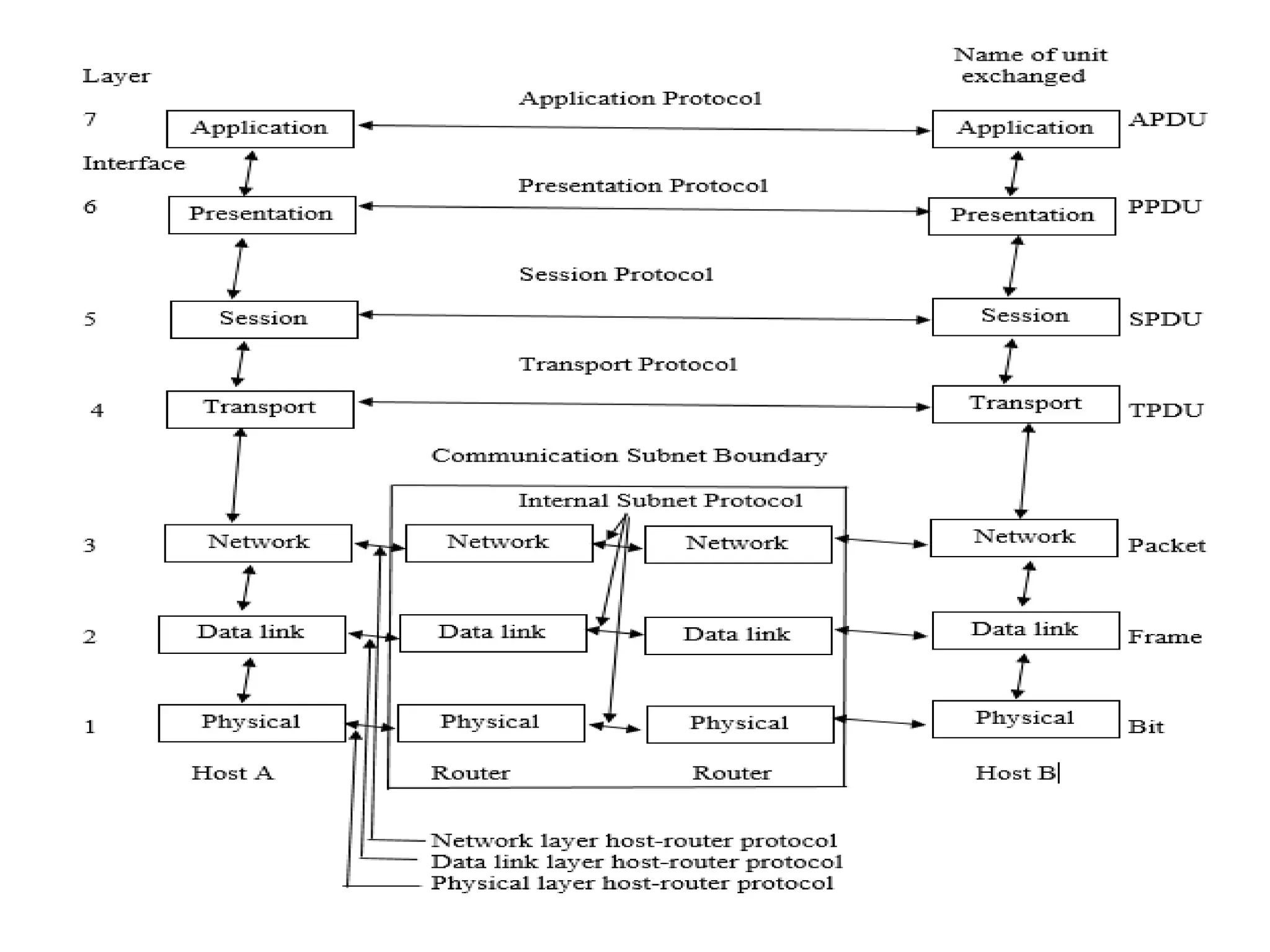
1. Protocol Hierarchies(layer structure)
A list of protocols used by a certain system, one protocol per
layer is called a protocol stack.
A set of layers and protocols is called a network architecture.
Most networks are organized as a stack of layers, one layer on
the top of another layer. The number of layers and their names
vary from network to network. Each layer has a specified
function and protocols. Thus we obtain a stack of protocols.
The main purpose of each of layers is just to offer and provide
services to higher layers that are present. Each and every layer
has some particular task or function.
The networks are organized and arranged as different layers or
levels simply to reduce and minimize complexity of design of
network software.
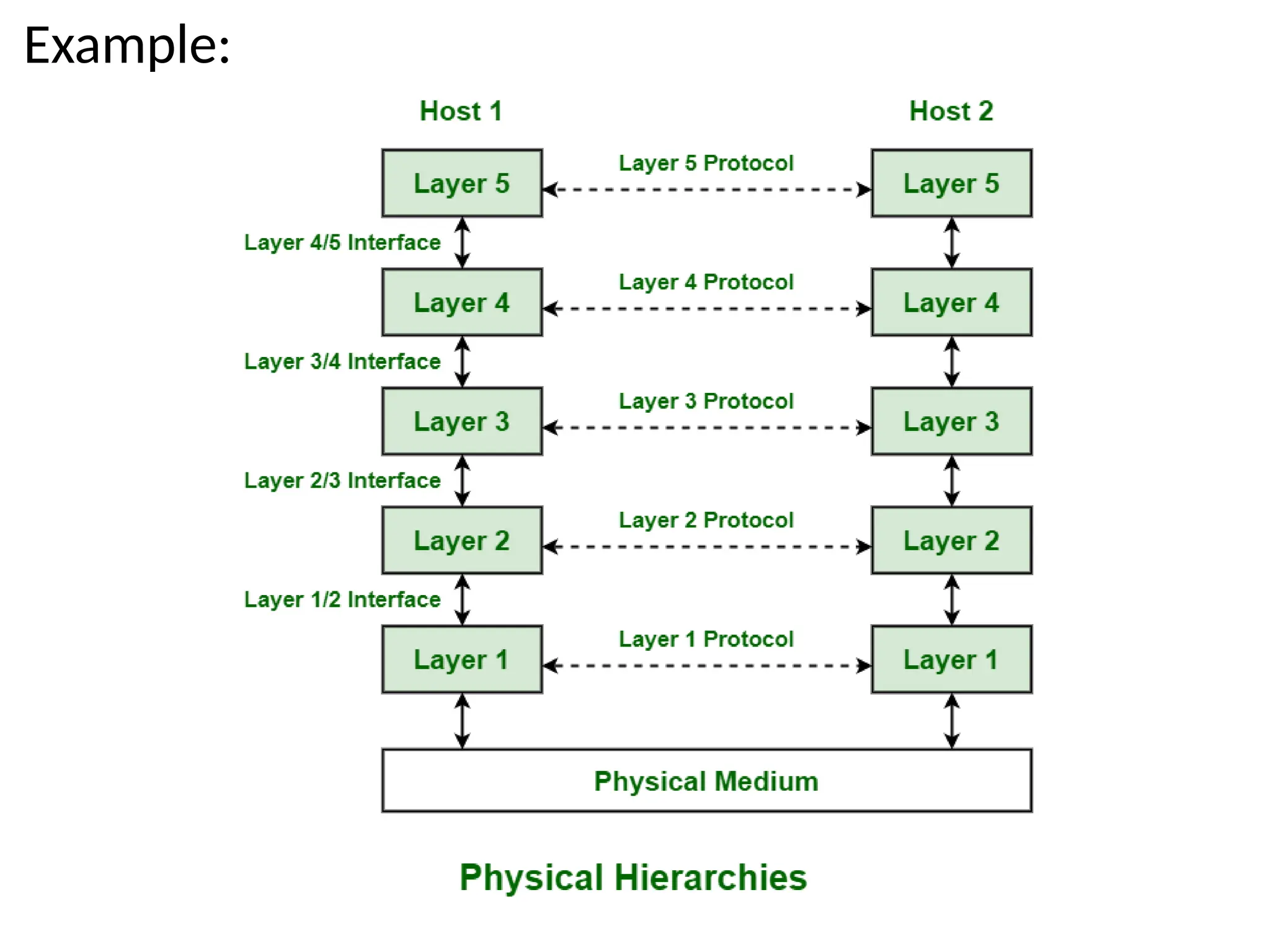
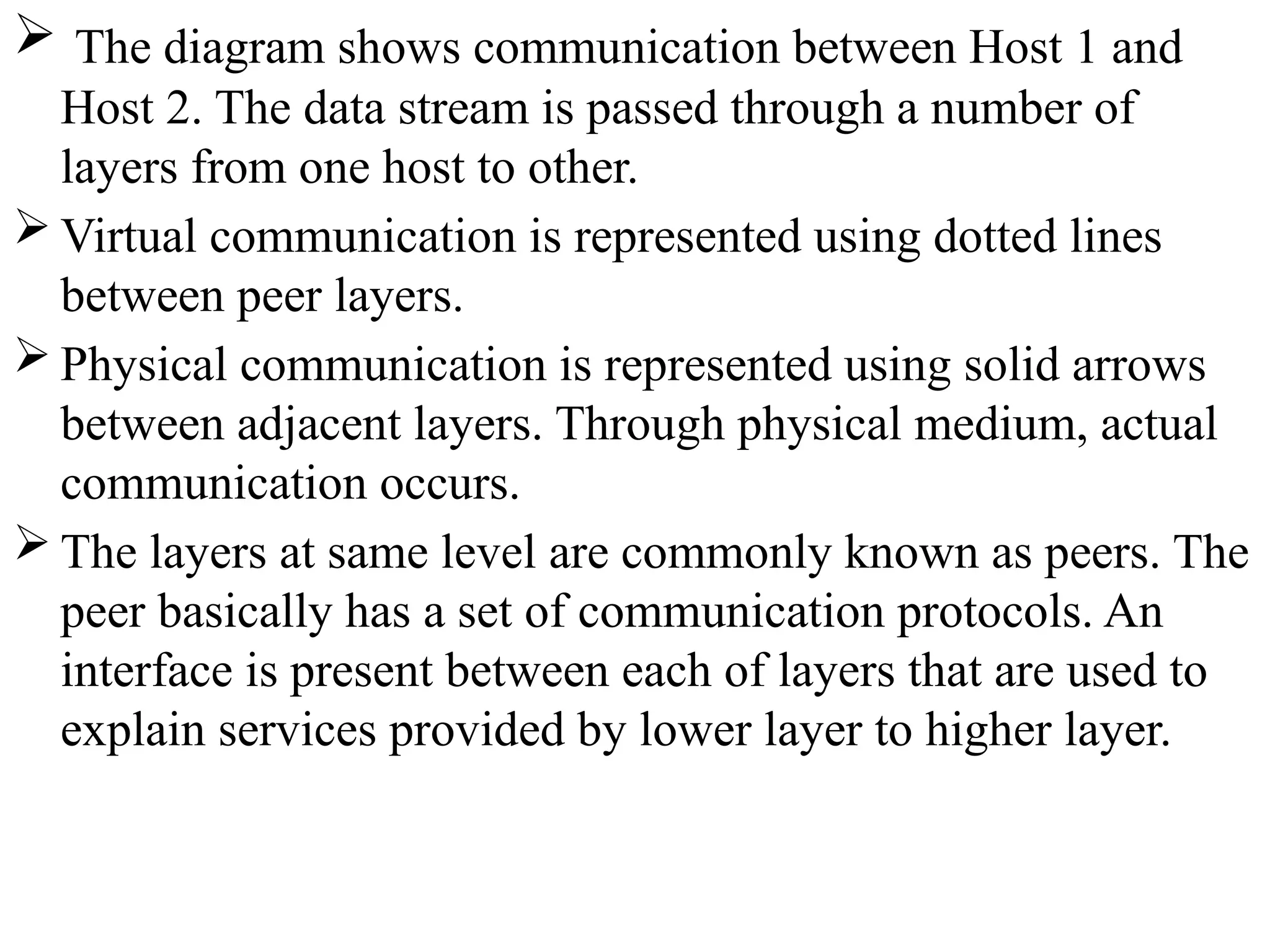
The diagramshows communication between Host 1 and
Host 2. The data stream is passed through a number of
layers from one host to other.
Virtual communication is represented using dotted lines
between peer layers.
Physical communication is represented using solid arrows
between adjacent layers. Through physical medium, actual
communication occurs.
The layers at same level are commonly known as peers. The
peer basically has a set of communication protocols. An
interface is present between each of layers that are used to
explain services provided by lower layer to higher layer.
83.
2. Design Issuesfor the Layers
A number of design issues exist for the layer to layer
approach of computer networks. Some of the main
design issues are as follows −
a) Reliability
Network channels and components may be unreliable,
resulting in loss of bits while data transfer. So, an
important design issue is to make sure that the
information transferred is not distorted.
b) Addressing: At a particular time, innumerable
messages are being transferred between large numbers
of computers. So, a naming or addressing system should
exist so that each layer can identify the sender and
receivers of each message.
84.
C) Data Transfer
we can transfer the data in simplex mode, half duplex mode
and full duplex mode.
d) Routing
There may be multiple paths from the source to the
destination. Routing involves choosing an optimal path
among all possible paths, in terms of cost and time. There
are several routing algorithms that are used in network
systems.
85.
e) Error Control
Unreliable channels introduce a number of errors in the
data streams that are communicated. So, the layers need to
agree upon common error detection and error correction
methods so as to protect data packets while they are
transferred.
f)Security
A major factor of data communication is to defend it against
threats .So, there should be adequate mechanisms to prevent
unauthorized access to data through authentication and
cryptography.
86.
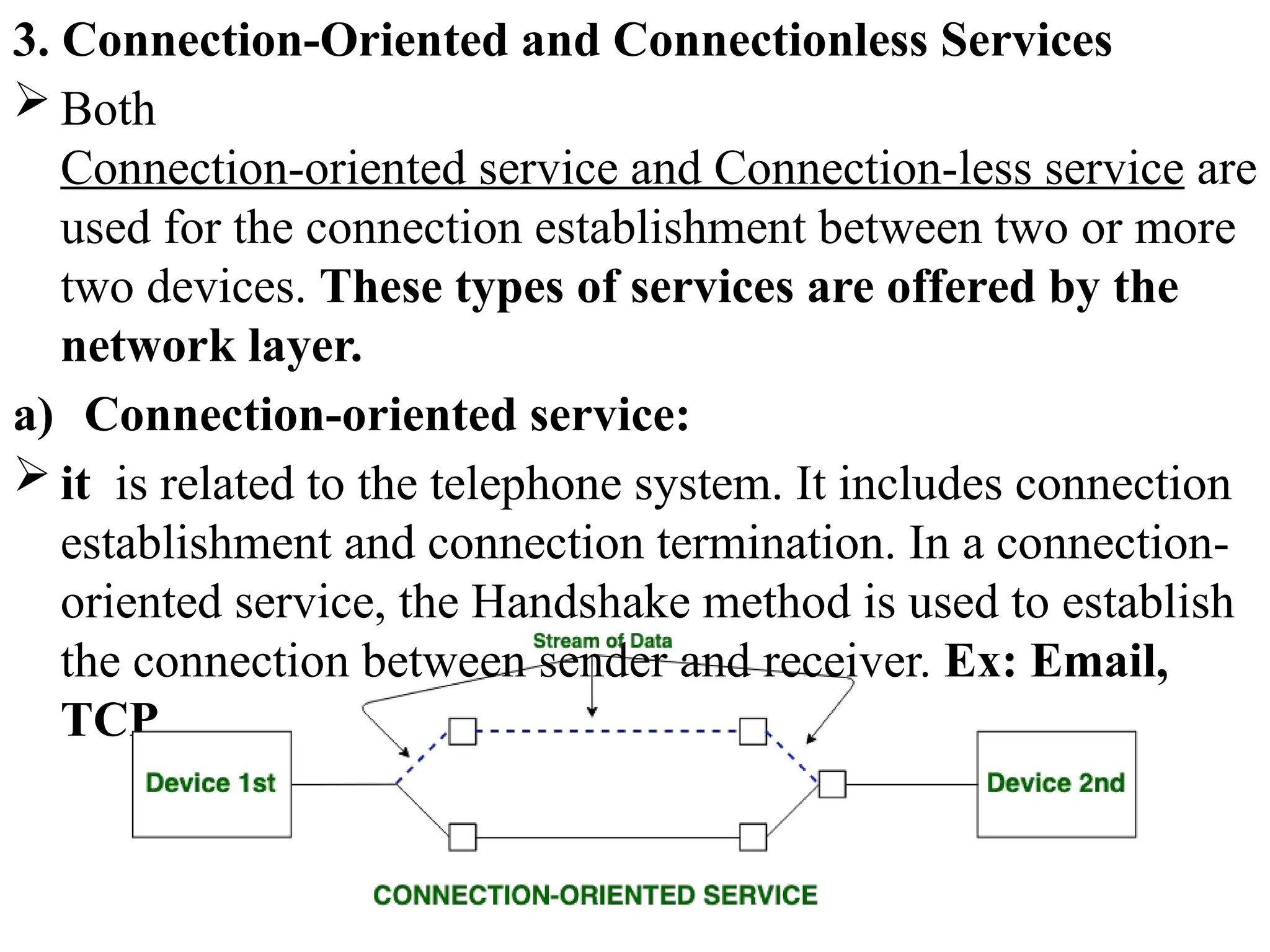
3. Connection-Oriented andConnectionless Services
Both
Connection-oriented service and Connection-less service are
used for the connection establishment between two or more
two devices. These types of services are offered by the
network layer.
a) Connection-oriented service:
it is related to the telephone system. It includes connection
establishment and connection termination. In a connection-
oriented service, the Handshake method is used to establish
the connection between sender and receiver. Ex: Email,
TCP
87.
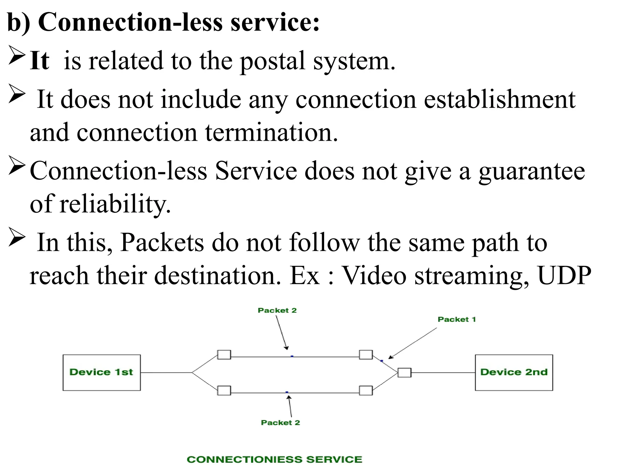
b) Connection-less service:
Itis related to the postal system.
It does not include any connection establishment
and connection termination.
Connection-less Service does not give a guarantee
of reliability.
In this, Packets do not follow the same path to
reach their destination. Ex : Video streaming, UDP
88.
S.NO
Connection-oriented
Service
Connection-less
Service
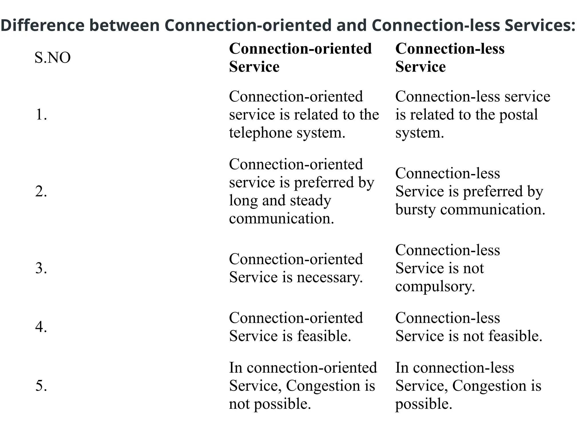
1.
Connection-oriented
service is relatedto the
telephone system.
Connection-less service
is related to the postal
system.
2.
Connection-oriented
service is preferred by
long and steady
communication.
Connection-less
Service is preferred by
bursty communication.
3.
Connection-oriented
Service is necessary.
Connection-less
Service is not
compulsory.
4.
Connection-oriented
Service is feasible.
Connection-less
Service is not feasible.
5.
In connection-oriented
Service, Congestion is
not possible.
In connection-less
Service, Congestion is
possible.
Difference between Connection-oriented and Connection-less Services:
89.
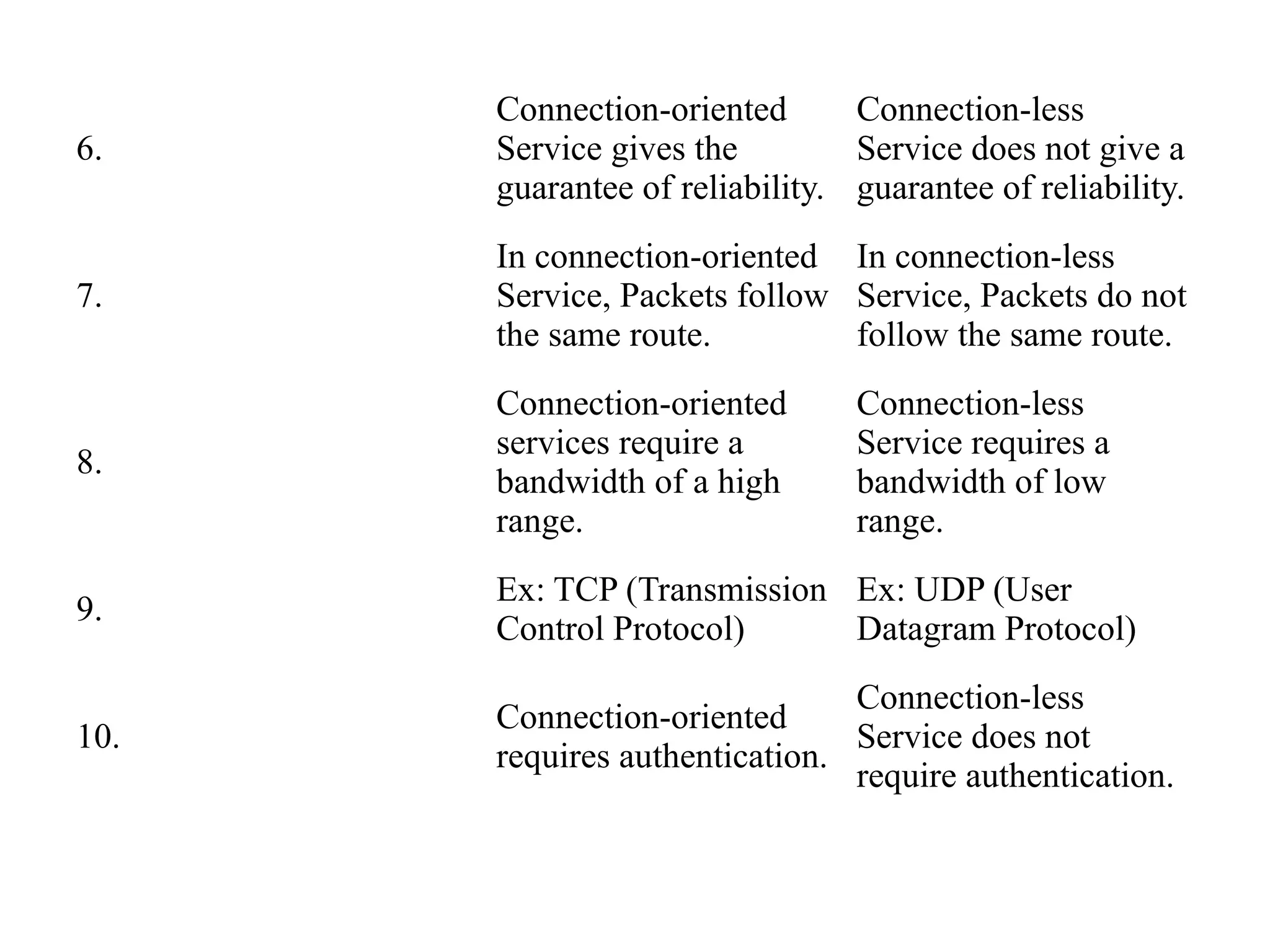
6.
Connection-oriented
Service gives the
guaranteeof reliability.
Connection-less
Service does not give a
guarantee of reliability.
7.
In connection-oriented
Service, Packets follow
the same route.
In connection-less
Service, Packets do not
follow the same route.
8.
Connection-oriented
services require a
bandwidth of a high
range.
Connection-less
Service requires a
bandwidth of low
range.
9.
Ex: TCP (Transmission
Control Protocol)
Ex: UDP (User
Datagram Protocol)
10.
Connection-oriented
requires authentication.
Connection-less
Service does not
require authentication.
90.
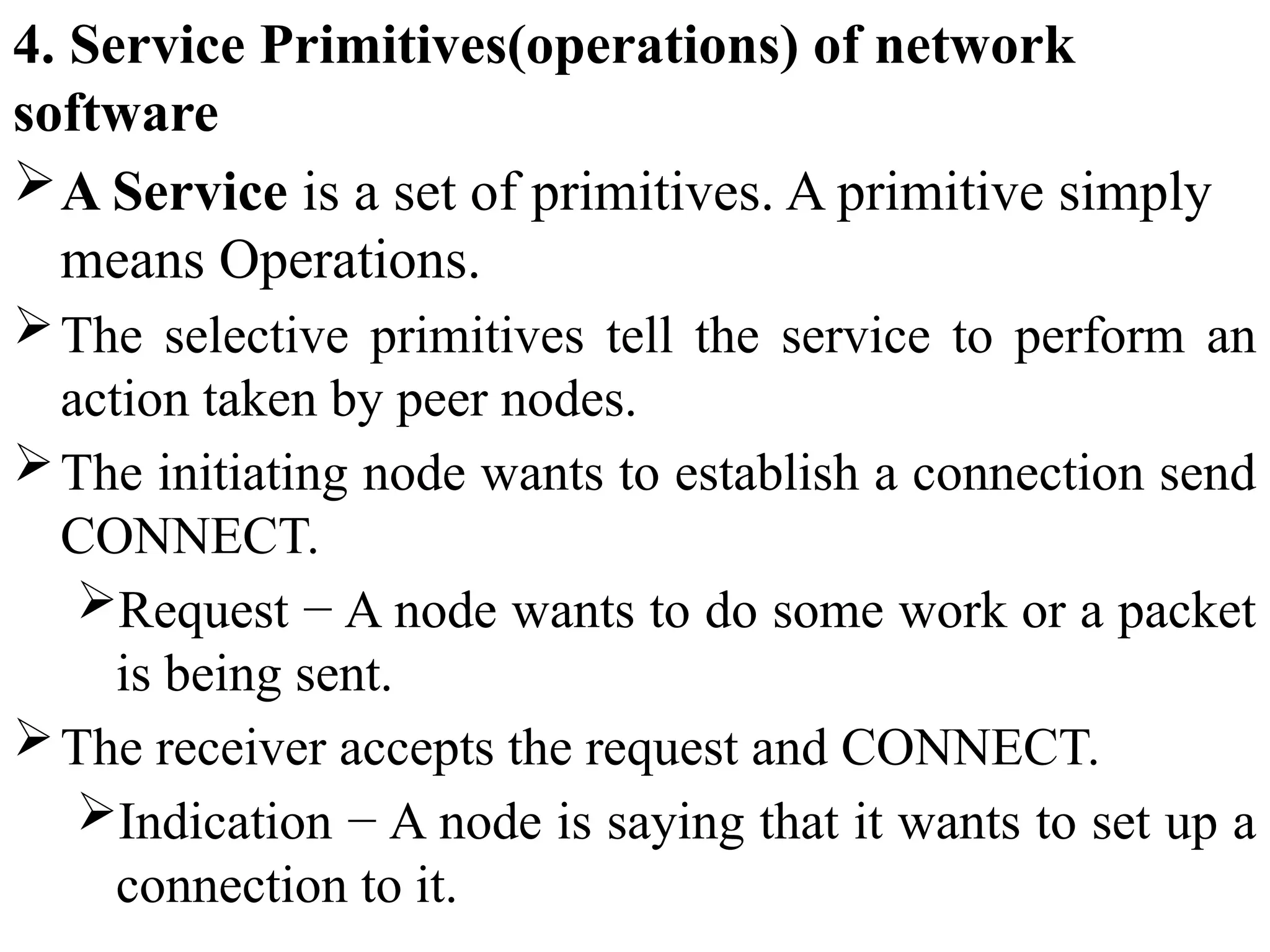
4. Service Primitives(operations)of network
software
A Service is a set of primitives. A primitive simply
means Operations.
The selective primitives tell the service to perform an
action taken by peer nodes.
The initiating node wants to establish a connection send
CONNECT.
Request − A node wants to do some work or a packet
is being sent.
The receiver accepts the request and CONNECT.
Indication − A node is saying that it wants to set up a
connection to it.
91.
The CONNECT. Thenode issuing the initial
CONNECT. request finds out what happened via a
CONNECT. Confirm primitive.
Response is primitive to tell whether it wants to
accept or reject the proposed connection.
These primitives can be used for a request-response
interaction in a client-server environment.
92.
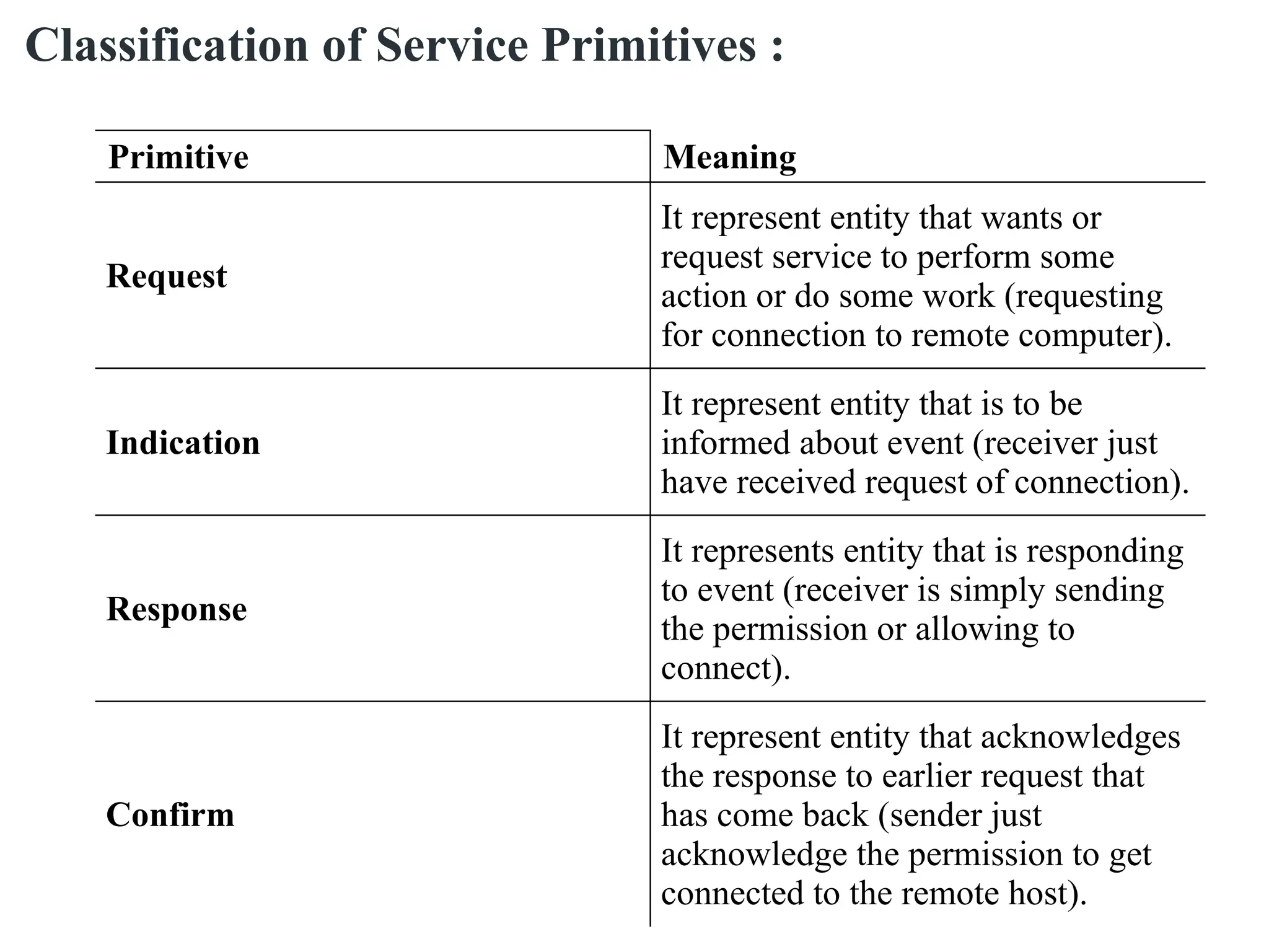
Primitive Meaning
Request
It represententity that wants or
request service to perform some
action or do some work (requesting
for connection to remote computer).
Indication
It represent entity that is to be
informed about event (receiver just
have received request of connection).
Response
It represents entity that is responding
to event (receiver is simply sending
the permission or allowing to
connect).
Confirm
It represent entity that acknowledges
the response to earlier request that
has come back (sender just
acknowledge the permission to get
connected to the remote host).
Classification of Service Primitives :
93.
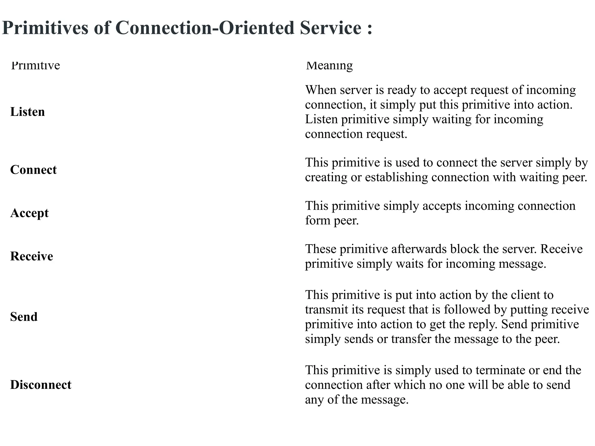
Primitive Meaning
Listen
When serveris ready to accept request of incoming
connection, it simply put this primitive into action.
Listen primitive simply waiting for incoming
connection request.
Connect
This primitive is used to connect the server simply by
creating or establishing connection with waiting peer.
Accept
This primitive simply accepts incoming connection
form peer.
Receive
These primitive afterwards block the server. Receive
primitive simply waits for incoming message.
Send
This primitive is put into action by the client to
transmit its request that is followed by putting receive
primitive into action to get the reply. Send primitive
simply sends or transfer the message to the peer.
Disconnect
This primitive is simply used to terminate or end the
connection after which no one will be able to send
any of the message.
Primitives of Connection-Oriented Service :
94.
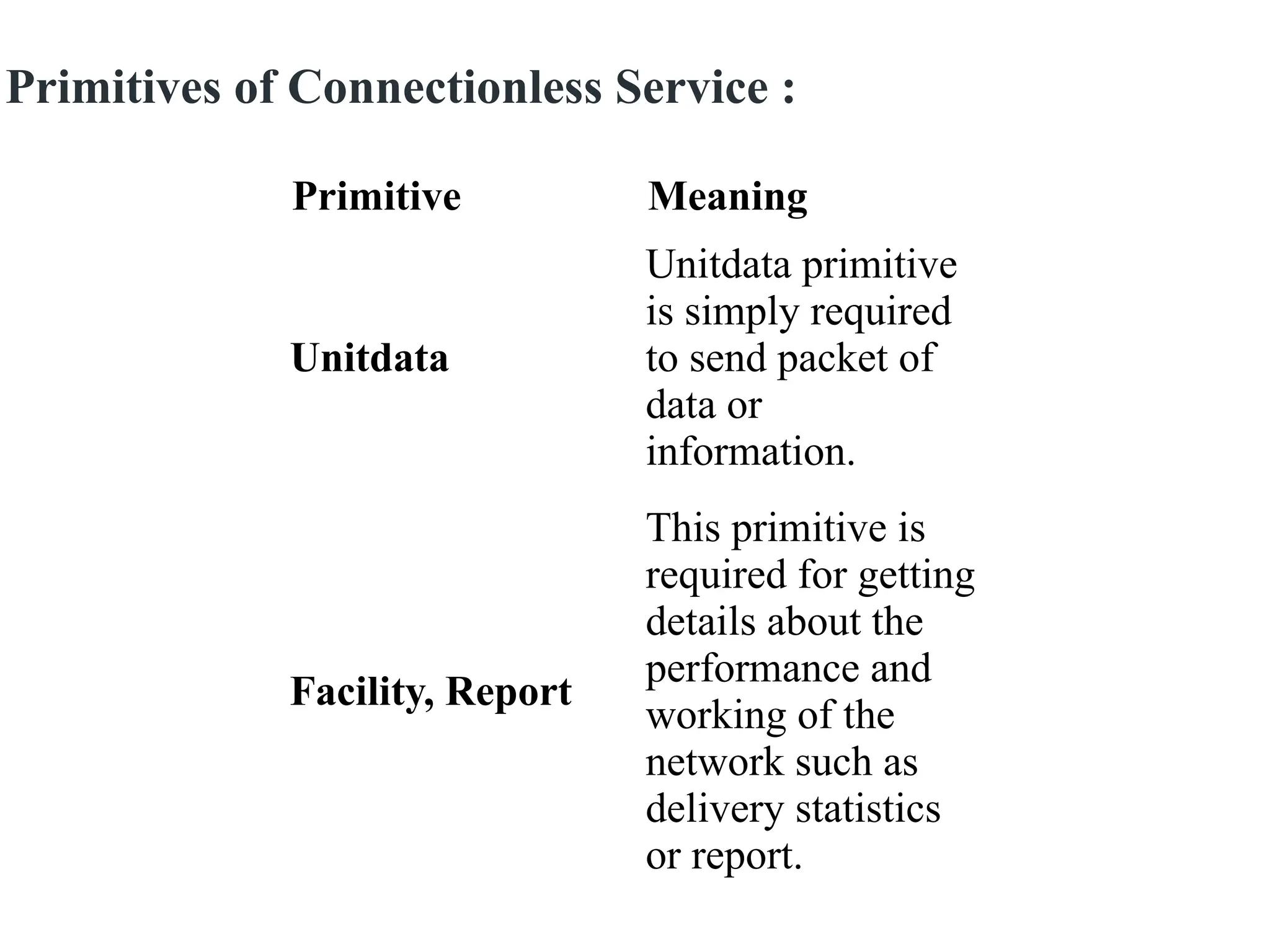
Primitive Meaning
Unitdata
Unitdata primitive
issimply required
to send packet of
data or
information.
Facility, Report
This primitive is
required for getting
details about the
performance and
working of the
network such as
delivery statistics
or report.
Primitives of Connectionless Service :
95.
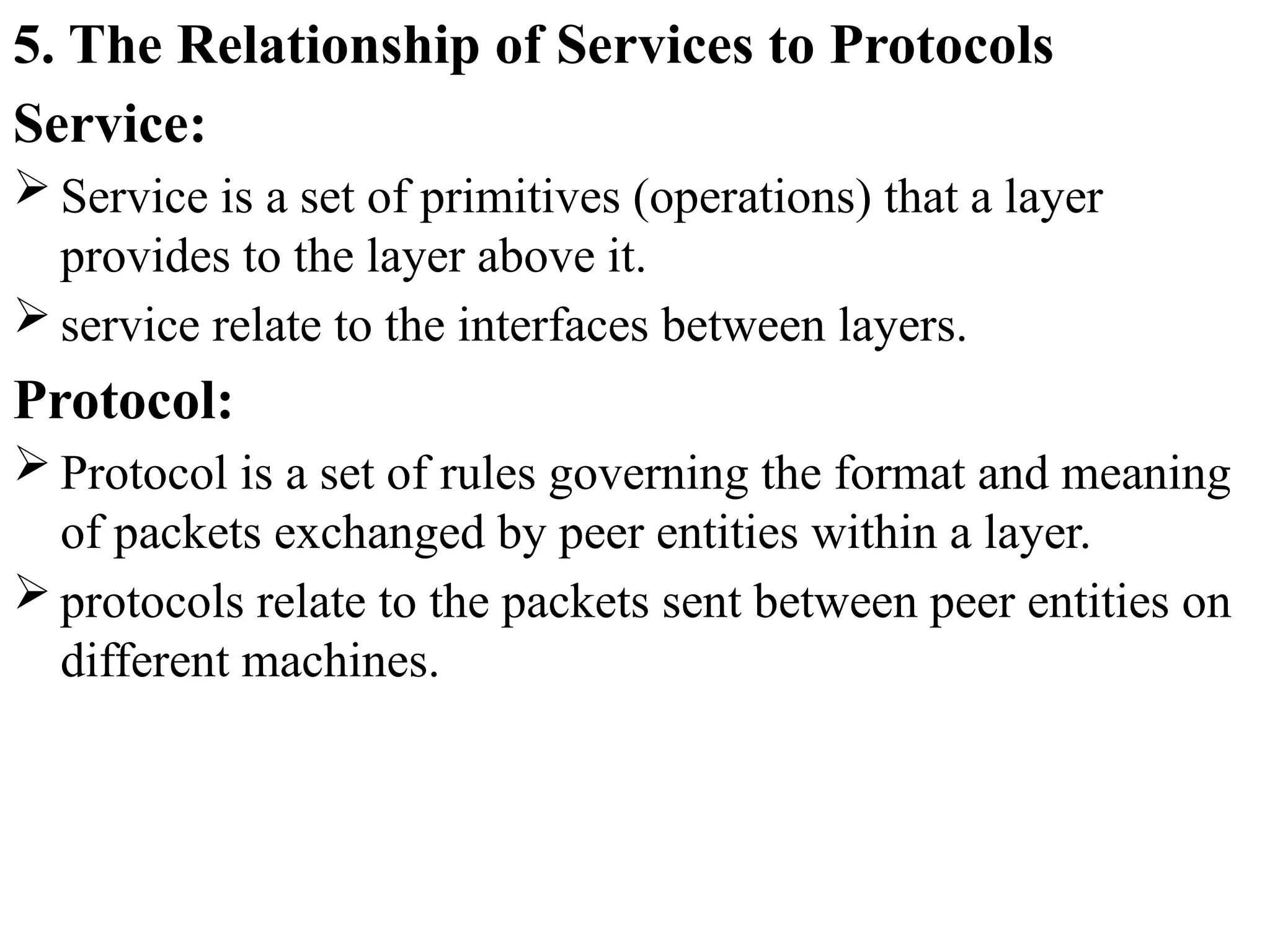
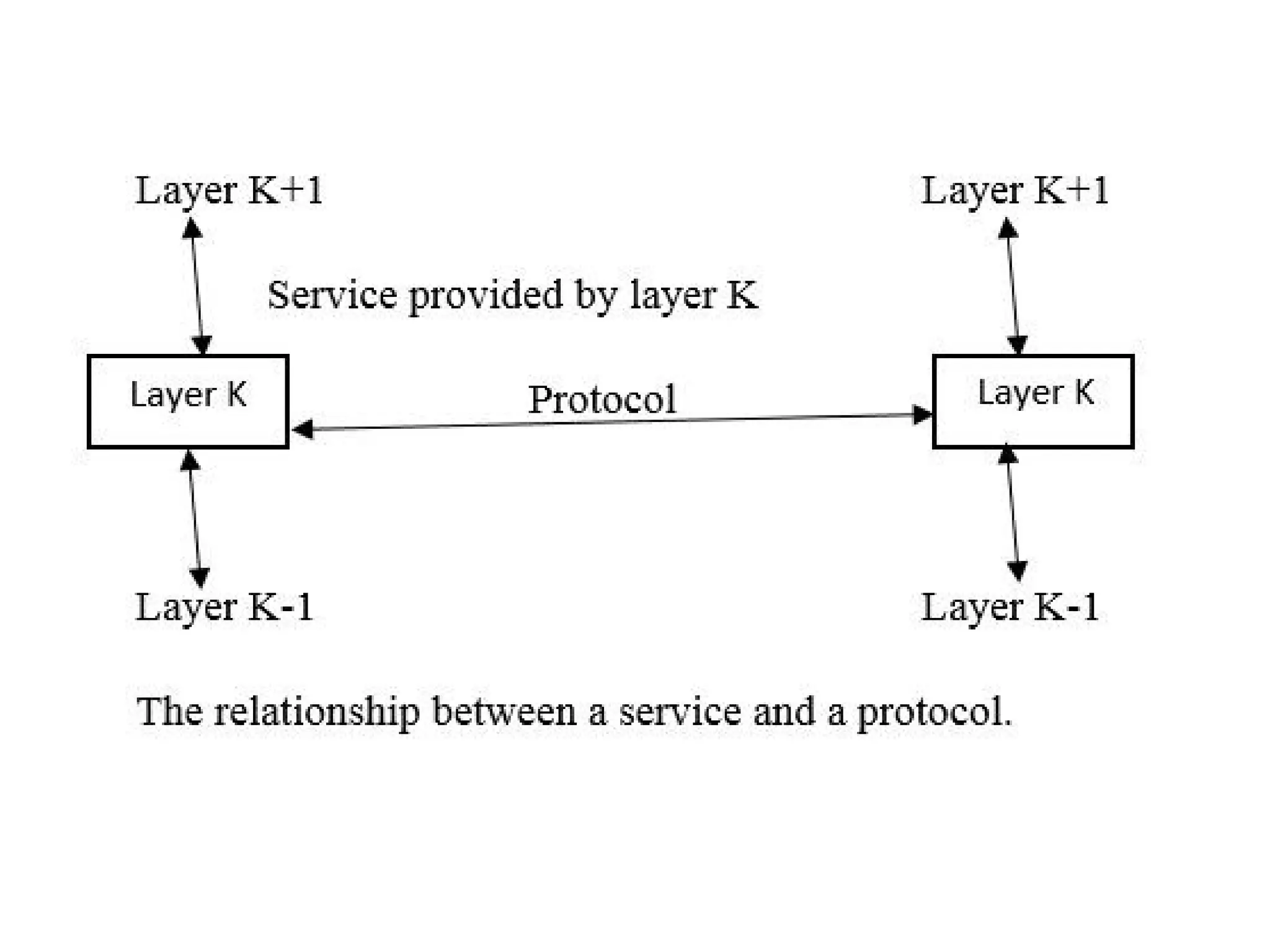
5. The Relationshipof Services to Protocols
Service:
Service is a set of primitives (operations) that a layer
provides to the layer above it.
service relate to the interfaces between layers.
Protocol:
Protocol is a set of rules governing the format and meaning
of packets exchanged by peer entities within a layer.
protocols relate to the packets sent between peer entities on
different machines.
97.
Reference Models
The OSIReference Model
OSI stands for Open Systems Interconnection. It has been
developed by ISO – ‘International Organization for
Standardization‘, in the year 1984.
It is a 7 layer architecture with each layer having specific
functionality to perform. All these 7 layers work
collaboratively (together)
to transmit the data from one person to another across the
globe.
99.
1. Physical Layer(Layer 1) :
The lowest layer of the OSI reference model is the physical
layer. It is responsible for the actual physical connection
between the devices.
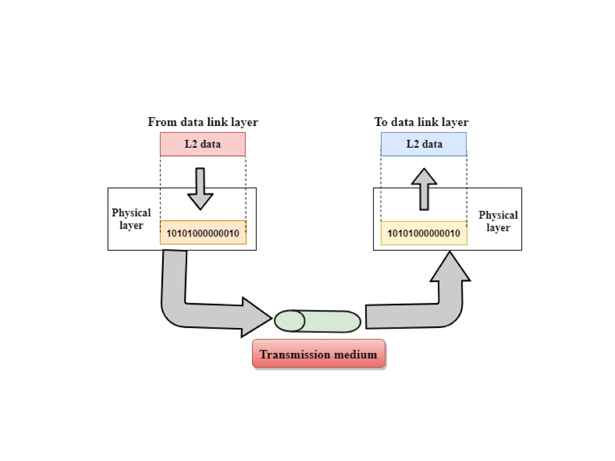
The physical layer contains information in the form
of bits. It is responsible for transmitting individual bits from
one node to the next. When receiving data, this layer will get
the signal received and convert it into 0s and 1s and send
them to the Data Link layer, which will put the frame back
together.
Hub, Repeater, Modem, Cables are Physical Layer
devices.
Network Layer, Data Link Layer, and Physical Layer are
also known as Lower Layers or Hardware Layers.
101.
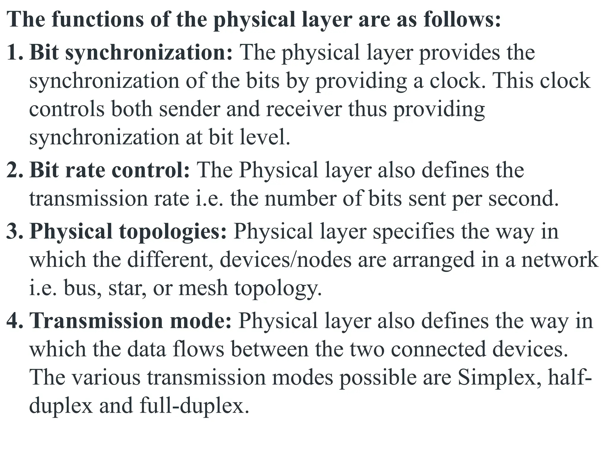
The functions ofthe physical layer are as follows:
1. Bit synchronization: The physical layer provides the
synchronization of the bits by providing a clock. This clock
controls both sender and receiver thus providing
synchronization at bit level.
2. Bit rate control: The Physical layer also defines the
transmission rate i.e. the number of bits sent per second.
3. Physical topologies: Physical layer specifies the way in
which the different, devices/nodes are arranged in a network
i.e. bus, star, or mesh topology.
4. Transmission mode: Physical layer also defines the way in
which the data flows between the two connected devices.
The various transmission modes possible are Simplex, half-
duplex and full-duplex.
102.
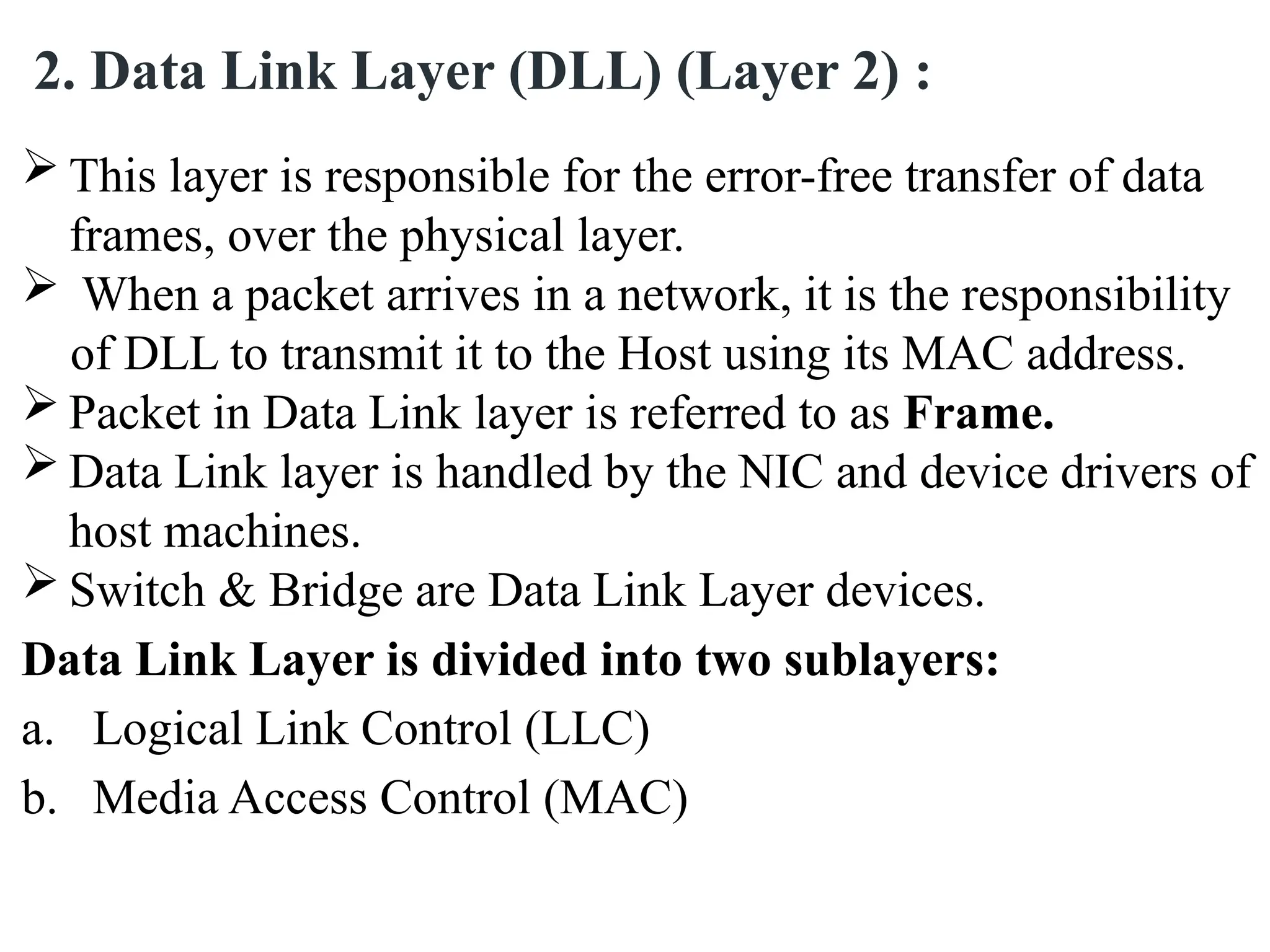
This layeris responsible for the error-free transfer of data
frames, over the physical layer.
When a packet arrives in a network, it is the responsibility
of DLL to transmit it to the Host using its MAC address.
Packet in Data Link layer is referred to as Frame.
Data Link layer is handled by the NIC and device drivers of
host machines.
Switch & Bridge are Data Link Layer devices.
Data Link Layer is divided into two sublayers:
a. Logical Link Control (LLC)
b. Media Access Control (MAC)
2. Data Link Layer (DLL) (Layer 2) :
103.
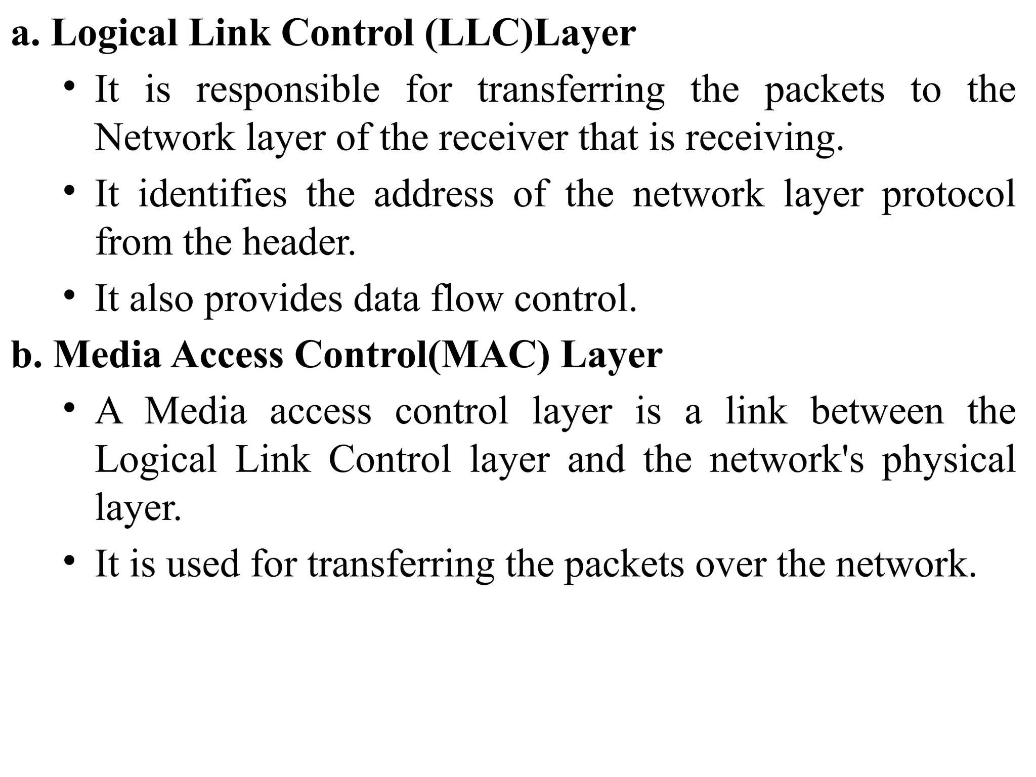
a. Logical LinkControl (LLC)Layer
• It is responsible for transferring the packets to the
Network layer of the receiver that is receiving.
• It identifies the address of the network layer protocol
from the header.
• It also provides data flow control.
b. Media Access Control(MAC) Layer
• A Media access control layer is a link between the
Logical Link Control layer and the network's physical
layer.
• It is used for transferring the packets over the network.
105.
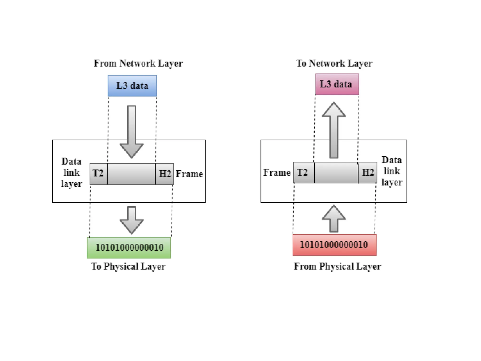
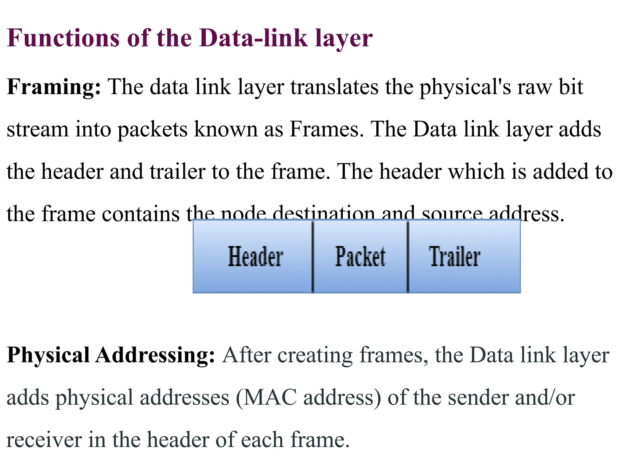
Functions of theData-link layer
Framing: The data link layer translates the physical's raw bit
stream into packets known as Frames. The Data link layer adds
the header and trailer to the frame. The header which is added to
the frame contains the node destination and source address.
Physical Addressing: After creating frames, the Data link layer
adds physical addresses (MAC address) of the sender and/or
receiver in the header of each frame.
106.
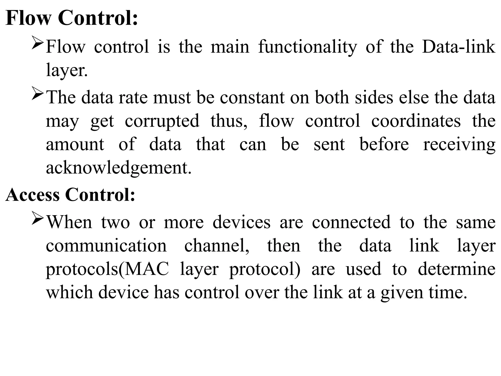
Flow Control:
Flow controlis the main functionality of the Data-link
layer.
The data rate must be constant on both sides else the data
may get corrupted thus, flow control coordinates the
amount of data that can be sent before receiving
acknowledgement.
Access Control:
When two or more devices are connected to the same
communication channel, then the data link layer
protocols(MAC layer protocol) are used to determine
which device has control over the link at a given time.
107.
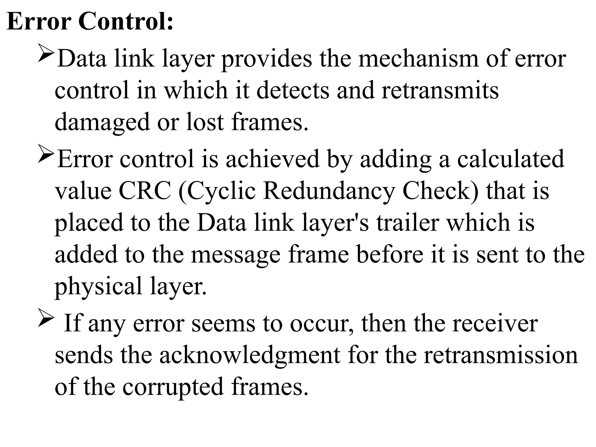
Error Control:
Data linklayer provides the mechanism of error
control in which it detects and retransmits
damaged or lost frames.
Error control is achieved by adding a calculated
value CRC (Cyclic Redundancy Check) that is
placed to the Data link layer's trailer which is
added to the message frame before it is sent to the
physical layer.
If any error seems to occur, then the receiver
sends the acknowledgment for the retransmission
of the corrupted frames.
108.
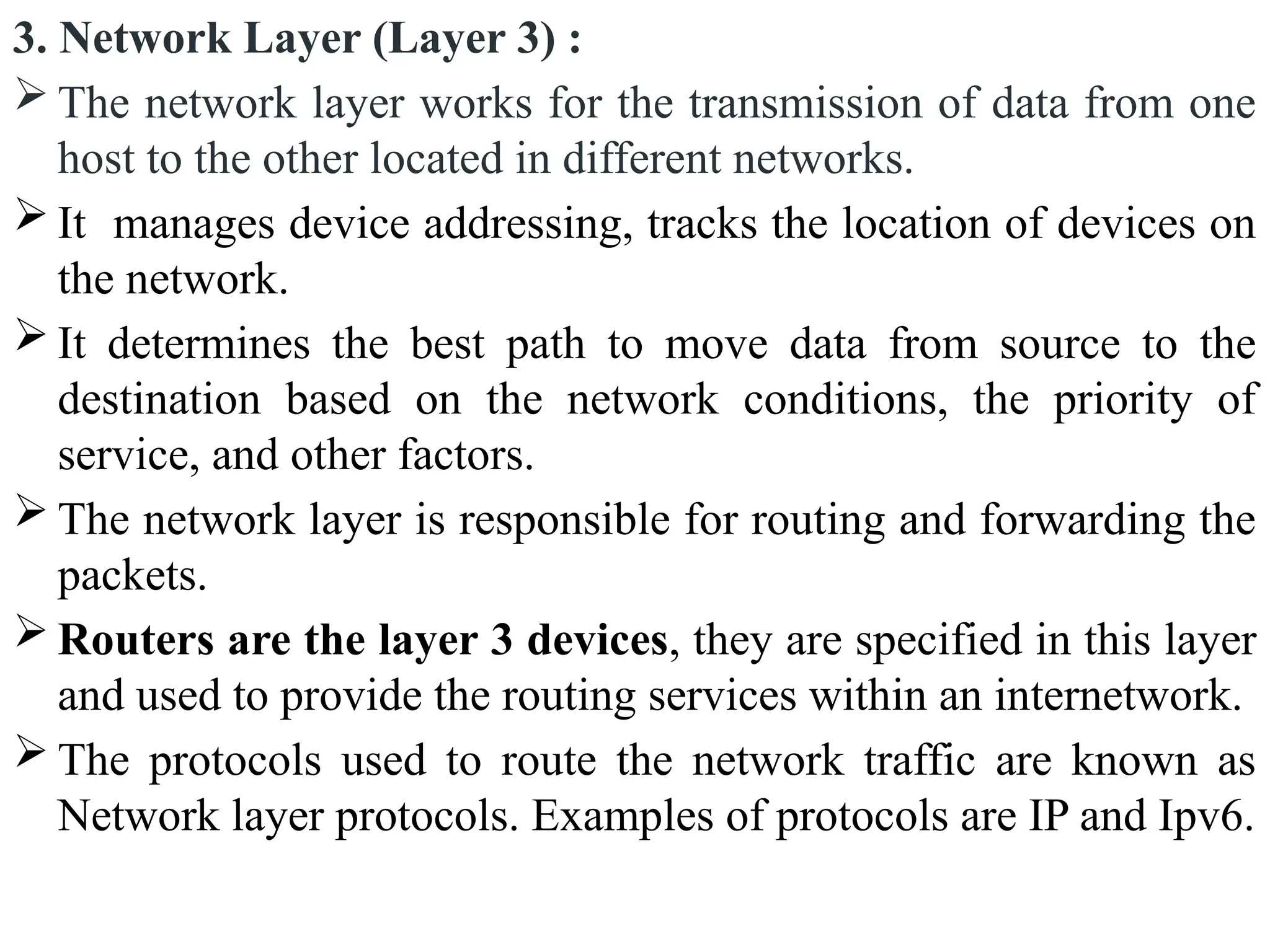
3. Network Layer(Layer 3) :
The network layer works for the transmission of data from one
host to the other located in different networks.
It manages device addressing, tracks the location of devices on
the network.
It determines the best path to move data from source to the
destination based on the network conditions, the priority of
service, and other factors.
The network layer is responsible for routing and forwarding the
packets.
Routers are the layer 3 devices, they are specified in this layer
and used to provide the routing services within an internetwork.
The protocols used to route the network traffic are known as
Network layer protocols. Examples of protocols are IP and Ipv6.
109.
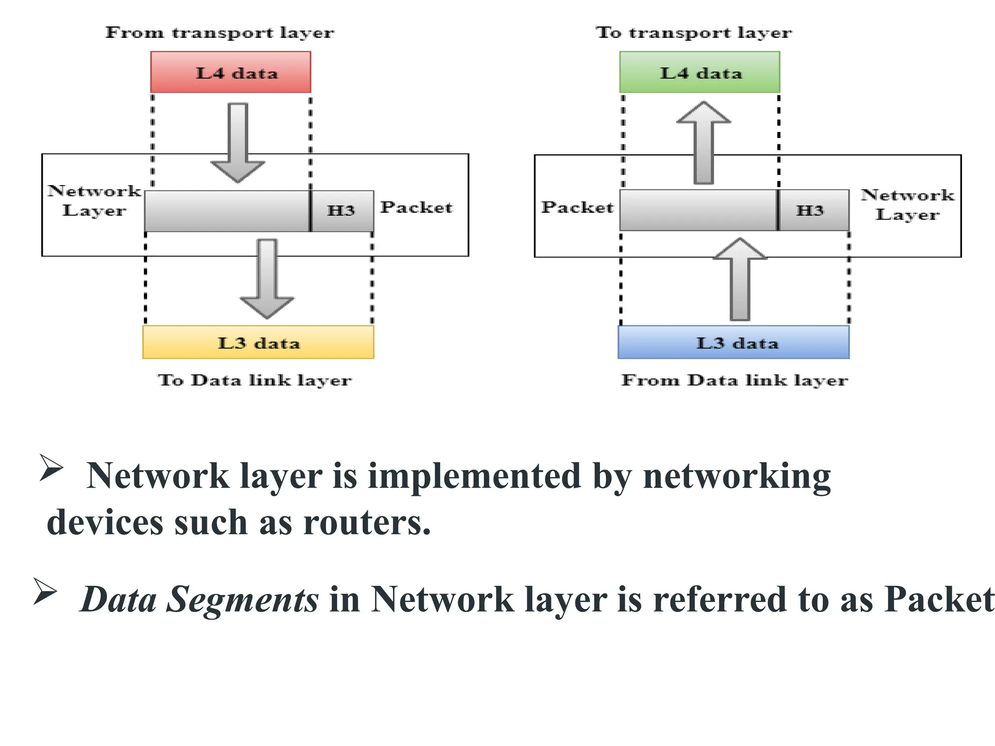
Network layeris implemented by networking
devices such as routers.
Data Segments in Network layer is referred to as Packet
110.
Functions of NetworkLayer:
Routing: Routing is the major component of the
network layer, and it determines the best optimal
path out of the multiple paths from source to the
destination.
Logical Addressing: In order to identify each
device on internetwork uniquely, the network layer
defines an addressing scheme. The sender &
receiver’s IP addresses are placed in the header by
the network layer. Such an address distinguishes
each device uniquely and universally.
111.
4. Transport Layer(Layer 4) :
The transport layer provides services to the application
layer and takes services from the network layer.
The data in the transport layer is referred to as Segments.
It is responsible for the End to End Delivery of the
complete message.
The transport layer also provides the acknowledgement
of the successful data transmission and re-transmits the
data if an error is found.
Transport layer is operated by the Operating System.
It is a part of the OS and communicates with the
Application Layer by making system calls.
Transport Layer is called as Heart of OSI model.
112.
The services orprotocols provided by the transport
layer :
A. Connection-Oriented Service: It is a three-
phase process that includes
– Connection Establishment
– Data Transfer
– Termination / disconnection
In this type of transmission, the receiving device sends
an acknowledgement, back to the source after a packet
or group of packets is received.
This type of transmission is reliable and secure.
Example: TCP(Transmission Control Protocol)
113.
B. Connectionless service:
It is a one-phase process and includes Data Transfer.
In this type of transmission, receiver does not send any
acknowledgment when the packet is received, the sender
does not wait for any acknowledgment. Therefore, this
makes a protocol unreliable.
Connection-oriented service is more reliable than
connectionless Service.
Example: User Datagram Protocol (UDP) is a transport
layer protocol.
115.
Functions of TransportLayer:
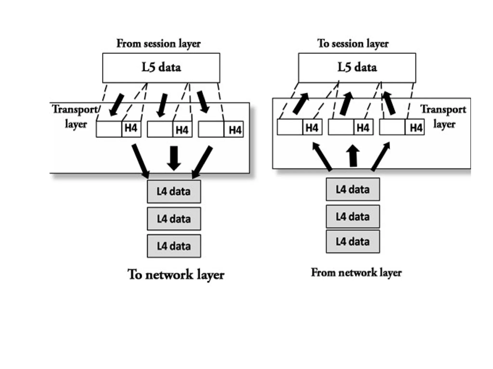
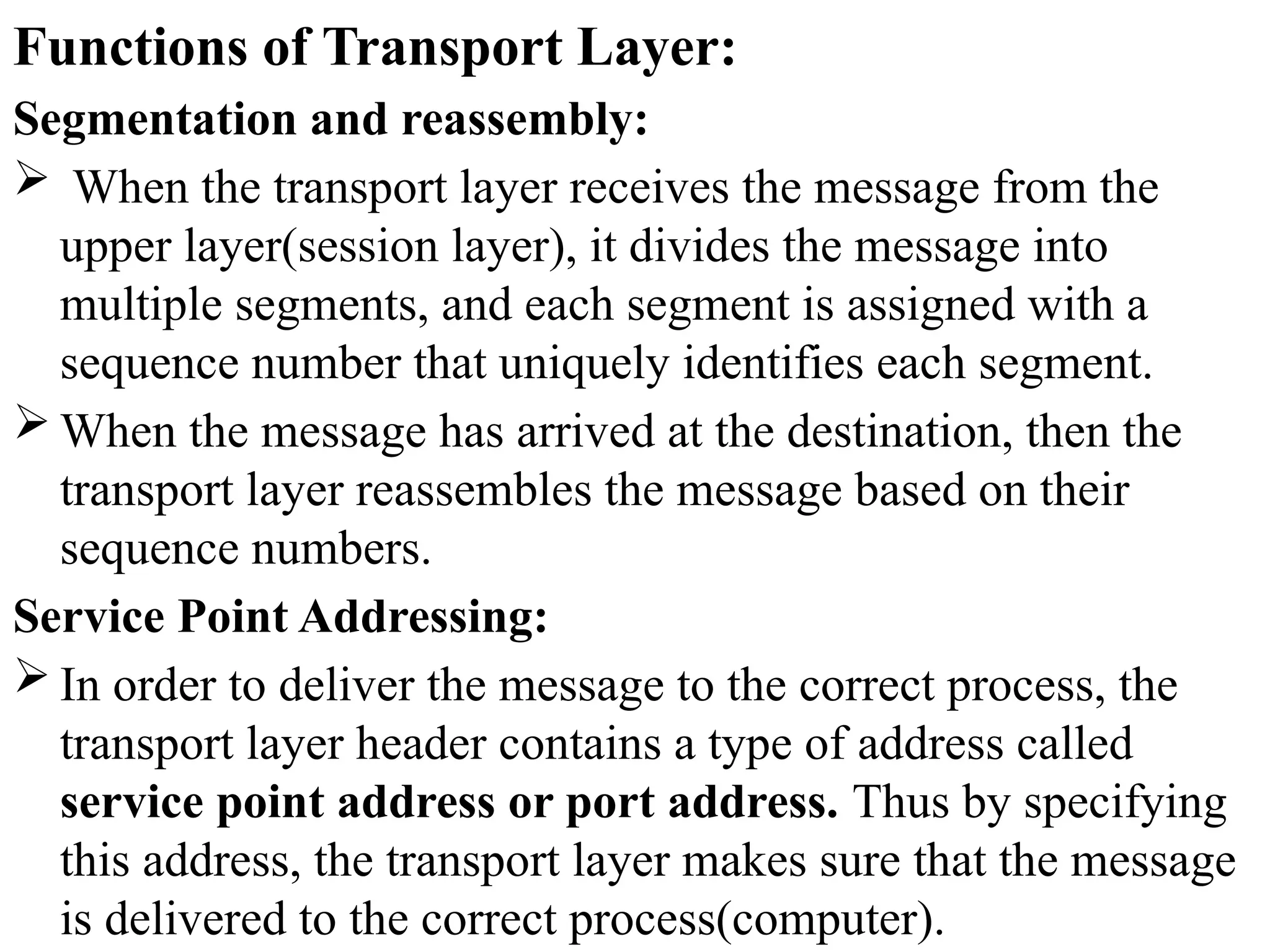
Segmentation and reassembly:
When the transport layer receives the message from the
upper layer(session layer), it divides the message into
multiple segments, and each segment is assigned with a
sequence number that uniquely identifies each segment.
When the message has arrived at the destination, then the
transport layer reassembles the message based on their
sequence numbers.
Service Point Addressing:
In order to deliver the message to the correct process, the
transport layer header contains a type of address called
service point address or port address. Thus by specifying
this address, the transport layer makes sure that the message
is delivered to the correct process(computer).
116.
5. Session Layer(Layer 5) :
This layer is responsible for the establishment of
connection, maintainance of sessions, authentication, and
also ensures security.
All the below 3 layers(including Session Layer) are
integrated as a single layer in the TCP/IP model as
“Application Layer”.
Implementation of these 3 layers is done by the network
application itself. These are also known as Upper
Layers or Software Layers.
118.
Functions of Sessionlayer:
1. Session establishment, maintenance, and
termination: The layer allows the two processes to
establish, use and terminate a connection.
2. Dialog Controller: The session layer allows two systems
to start communication with each other in half-duplex or
full-duplex.
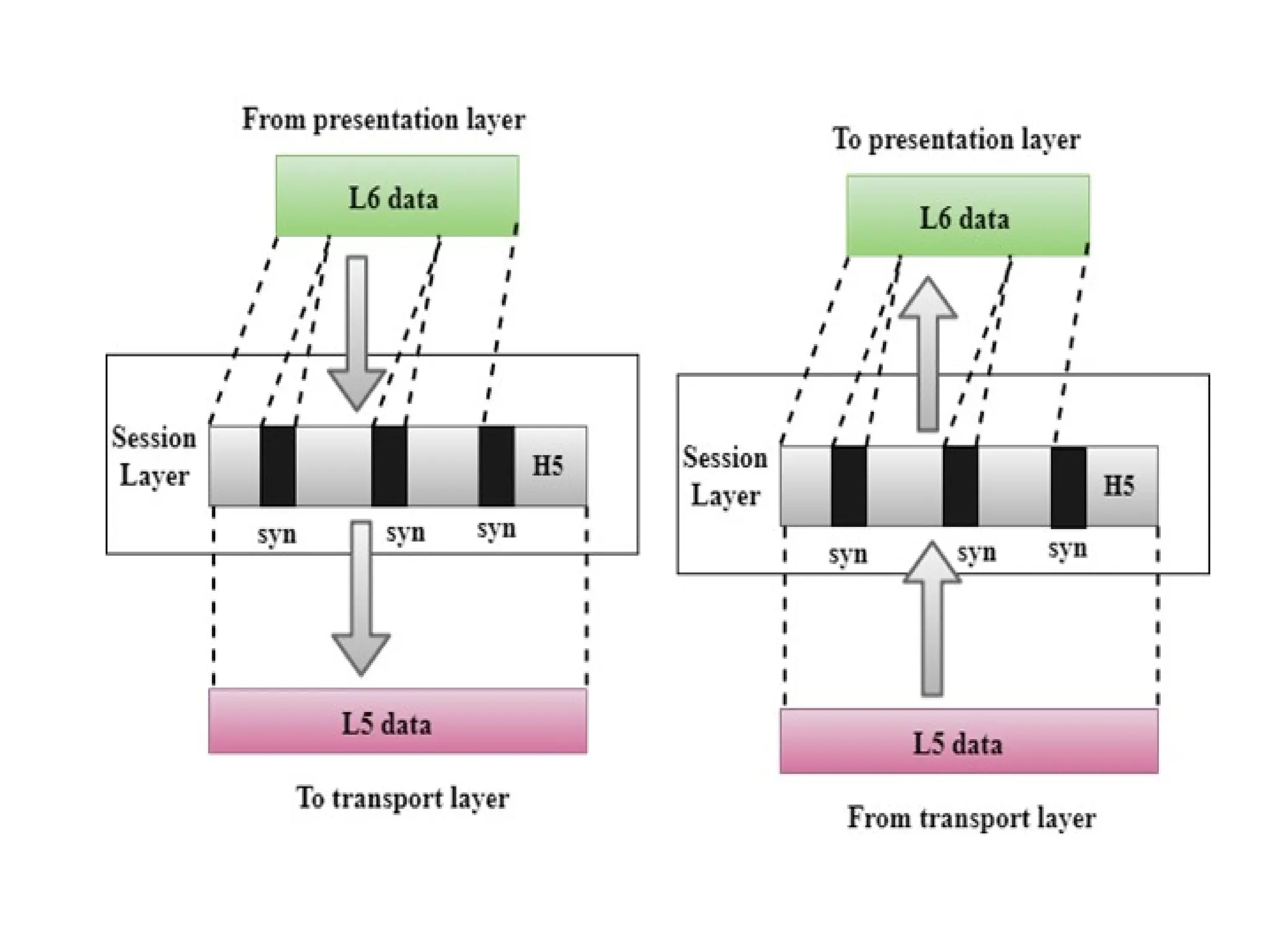
3. Synchronization: Session layer adds some checkpoints
when transmitting the data in a sequence. If some error
occurs in the middle of the transmission of data, then the
transmission will take place again from the checkpoint.
This process is known as Synchronization and recovery.
119.
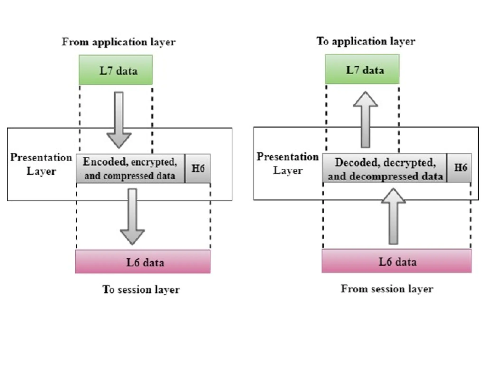
6. Presentation Layer(Layer 6):
The presentation layer is also called the Translation
layer.
The data from the application layer is extracted here and
manipulated as per the required format to transmit over
the network.
The functions of the presentation layer are :
Translation: For example, ASCII to EBCDIC.
Encryption/ Decryption: Data encryption translates
the data into another form or code. The encrypted data
is known as the ciphertext and the decrypted data is
known as plain text. A key value is used for encrypting
as well as decrypting data.
Compression: Reduces the number of bits that need to
be transmitted on the network.
121.
7. Application Layer(Layer 7) :
It is a very top of the OSI Reference Model in the stack of
layers, we find the Application layer which is implemented
by the network applications.
These applications produce the data, which has to be
transferred over the network.
This layer also serves as a window for the application
services to access the network and for displaying the
received information to the user.
Example: Application – Browsers, Skype Messenger, etc.
Application Layer is also called Desktop Layer
123.
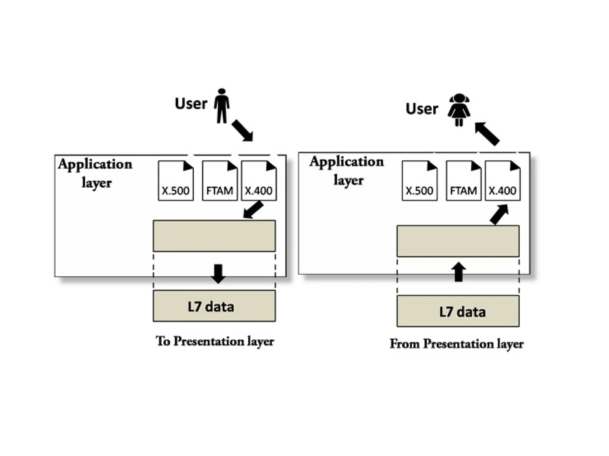
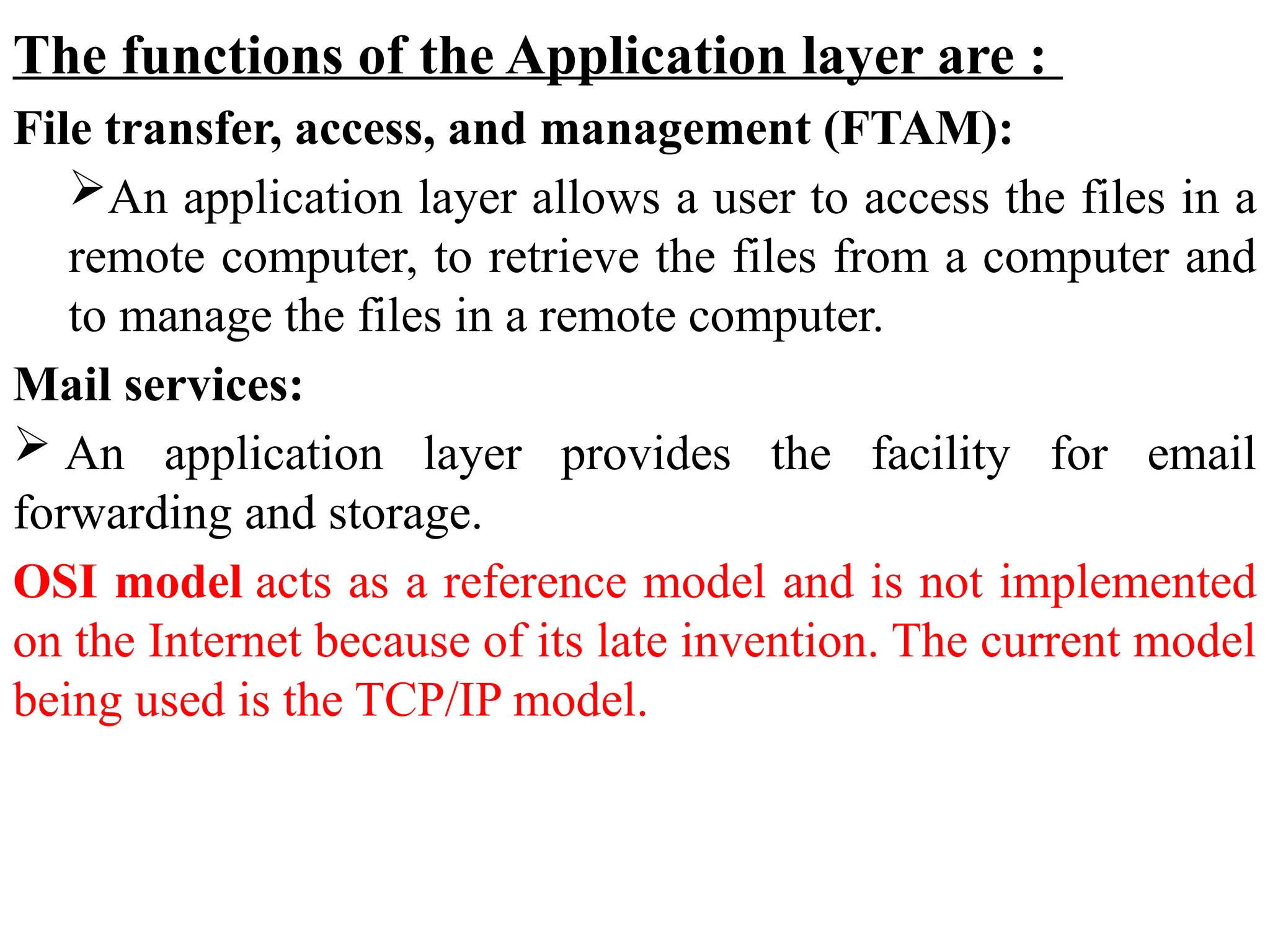
The functions ofthe Application layer are :
File transfer, access, and management (FTAM):
An application layer allows a user to access the files in a
remote computer, to retrieve the files from a computer and
to manage the files in a remote computer.
Mail services:
An application layer provides the facility for email
forwarding and storage.
OSI model acts as a reference model and is not implemented
on the Internet because of its late invention. The current model
being used is the TCP/IP model.
124.
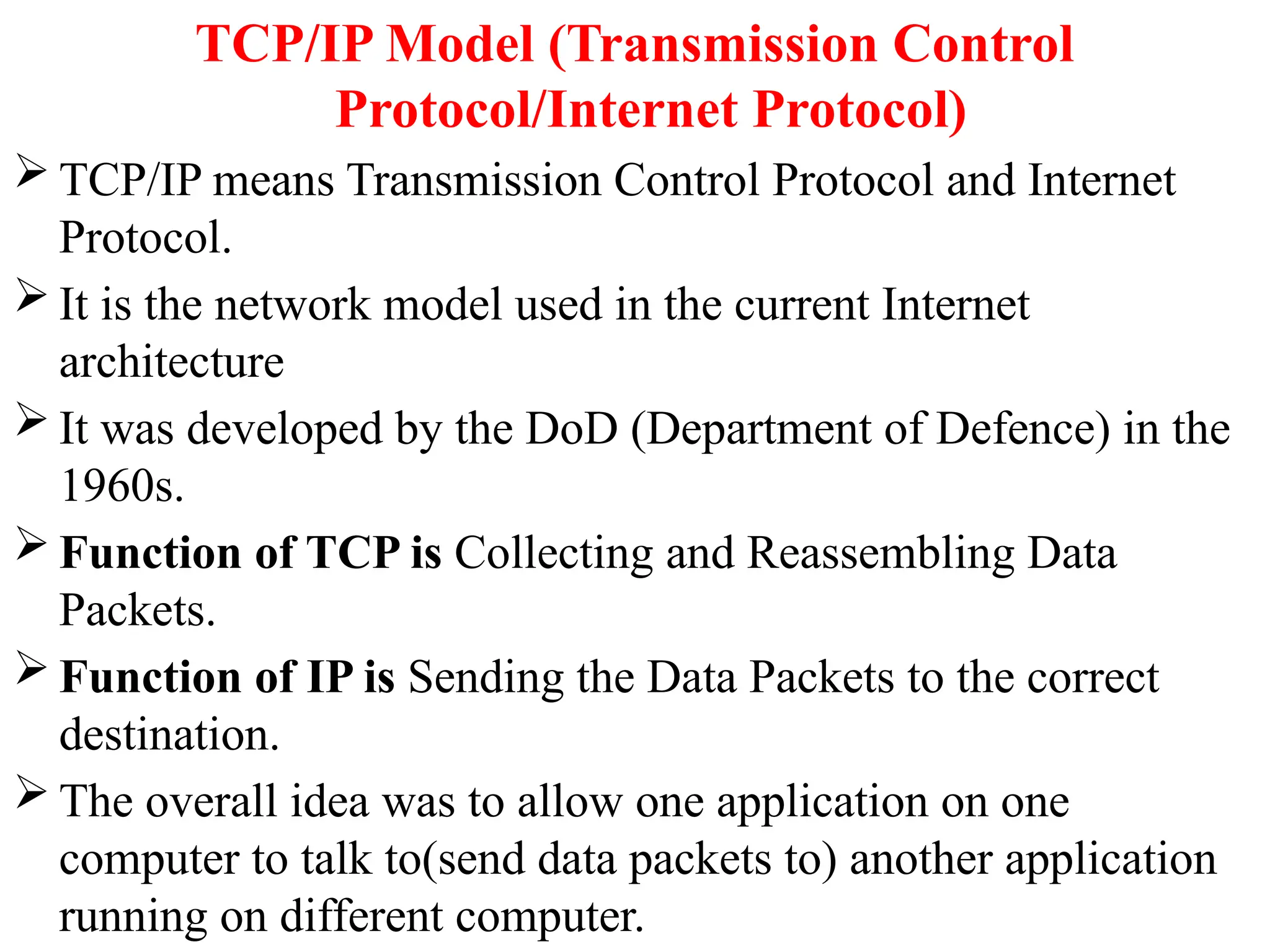
TCP/IP Model (TransmissionControl
Protocol/Internet Protocol)
TCP/IP means Transmission Control Protocol and Internet
Protocol.
It is the network model used in the current Internet
architecture
It was developed by the DoD (Department of Defence) in the
1960s.
Function of TCP is Collecting and Reassembling Data
Packets.
Function of IP is Sending the Data Packets to the correct
destination.
The overall idea was to allow one application on one
computer to talk to(send data packets to) another application
running on different computer.
125.
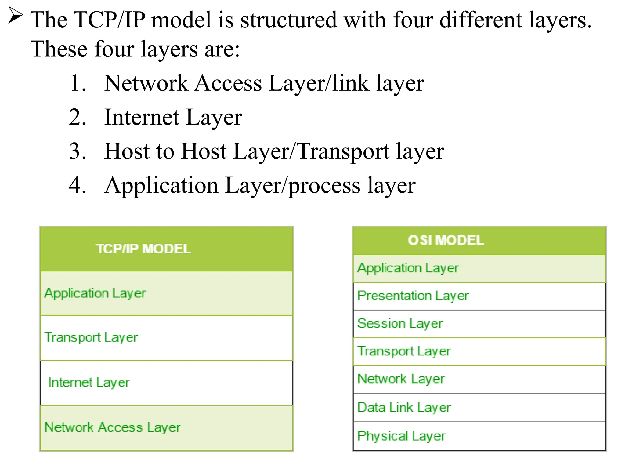
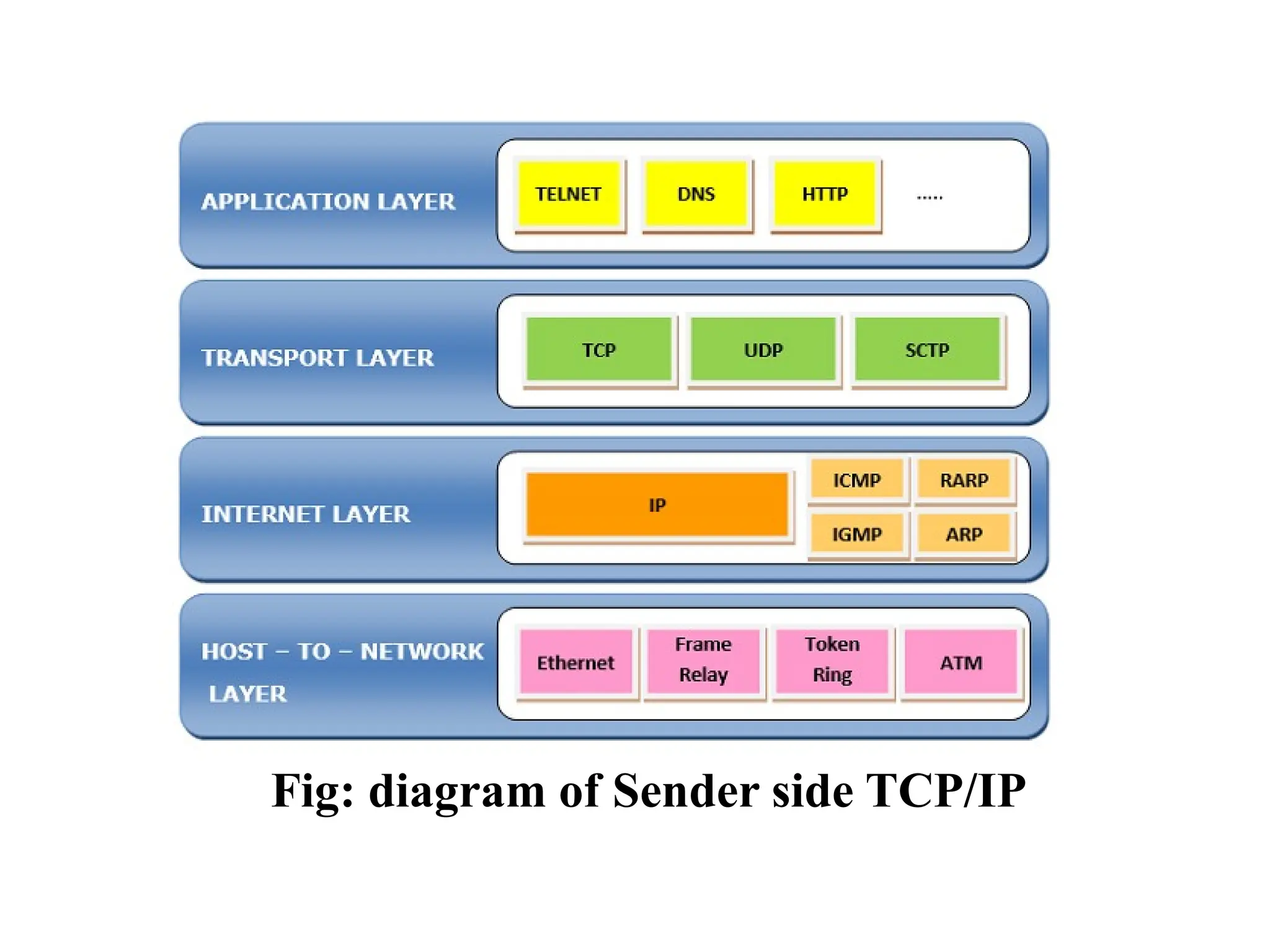
The TCP/IPmodel is structured with four different layers.
These four layers are:
1. Network Access Layer/link layer
2. Internet Layer
3. Host to Host Layer/Transport layer
4. Application Layer/process layer
1. Network AccessLayer/link layer(Layer 1)
The first layer is the Process layer/application layer on the behalf of
the sender and Network Access layer on the behalf of the receiver.
A network layer is the lowest layer of the TCP/IP model.
A network layer is the combination of the Physical layer and Data
Link layer defined in the OSI reference model.
It defines how the data should be sent physically through the
network.
This layer is mainly responsible for the transmission of the data
between two devices on the same network.
128.
The functionscarried out by this layer are encapsulating the
IP datagram into frames transmitted by the network and
mapping of IP addresses into physical addresses(MAC
address).
The protocols used by this layer are ethernet, token ring,
frame relay..etc.
129.
2. Internet Layer(Layer2)
An internet layer is the second layer of the TCP/IP model.
An internet layer is also known as the network layer.
It defines the protocols which are responsible for logical
transmission of data over the entire network.
Following are the protocols used in this layer
are:
I. IP Protocol: IP protocol is used in this layer, and it is the
most significant part of the entire TCP/IP suite.
Following are the responsibilities of this protocol:
• IP Addressing: This protocol implements logical host
addresses known as IP addresses. The IP addresses are used
by the internet and higher layers to identify the device and to
provide internetwork routing.
130.
• Host-to-host communication:It determines the path
through which the data is to be transmitted.
• Data Encapsulation and Formatting: An IP protocol
accepts the data from the transport layer protocol. An IP
protocol ensures that the data is sent and received securely,
it encapsulates the data into message known as IP datagram.
II. ARP Protocol
• ARP stands for Address Resolution Protocol.
• ARP is a network layer protocol which is used to find the
physical address from the IP address.
131.
III. ICMP Protocol
•ICMP stands for Internet Control Message Protocol.
• It is a mechanism used by the hosts or routers to send
notifications regarding datagram problems back to the
sender.
• A datagram travels from router-to-router until it reaches its
destination. If a router is unable to route the data because of
some unusual conditions such as disabled links, a device is
on fire or network congestion, then the ICMP protocol is
used to inform the sender that the datagram is undeliverable.
132.
3. Host toHost Layer/Transport layer
It is responsible for end-to-end communication and error-free
delivery of data.
The two protocols used in the transport layer are User Datagram protocol
and Transmission control protocol.
I. User Datagram Protocol (UDP)
• It provides connectionless service and end-to-end delivery of
transmission.
• It is an unreliable protocol as it discovers the errors but not specify
the error.
• User Datagram Protocol discovers the error, and ICMP protocol
reports the error to the sender that user datagram has been damaged.
133.
• UDP isgood protocol for data flowing in one
direction(means it doesn’t send a acknowledgement to the
sender).
• UDP does not guarantee ordered delivery of data.
• UDP is suitable protocol for streaming applications
such as multimedia streaming.
II. Transmission Control Protocol (TCP)
• It provides a full transport layer services to applications.
• It creates a virtual circuit between the sender and receiver,
and it is active for the duration of the transmission.
134.
• TCP isa reliable protocol as it detects the error and
retransmits the damaged frames. Therefore, it ensures all the
segments must be received and acknowledged before the
transmission is considered to be completed and a virtual
circuit is discarded.
• At the sending end, TCP divides the whole message into
smaller units known as segment, and each segment contains
a sequence number which is required for reordering the
frames to form an original message.
• At the receiving end, TCP collects all the segments and
reorders them based on sequence numbers.
135.
4. Application Layer/processlayer
Three layers of the OSI Model: Application, Presentation
and Sessions, when combined together, they perform similar
functions as the Application Layer of the TCP/IP model.
An application layer is the topmost layer in the TCP/IP
model.
It is responsible for handling high-level protocols, issues of
representation.
This layer allows the user to interact with the application.
When one application layer protocol wants to communicate
with another application layer, it forwards its data to the
transport layer.
136.
There isan ambiguity occurs in the application layer. Every
application cannot be placed inside the application layer
except those who interact with the communication system.
For example: text editor cannot be considered in
application layer while web browser using HTTP protocol
to interact with the network where HTTP protocol is an
application layer protocol.
Following are the main protocols used in the
application layer:
HTTP: HTTP stands for Hypertext transfer protocol.
This protocol allows us to access the data over the
world wide web. It transfers the data in the form of
plain text, audio, video.
137.
SMTP: SMTPstands for Simple mail transfer protocol.
The TCP/IP protocol that supports the e-mail is known as a
Simple mail transfer protocol. This protocol is used to send
the data to another e-mail address.
DNS: DNS stands for Domain Name System. An IP address
is used to identify the connection of a host to the internet
uniquely. But, people prefer to use the names instead of
addresses. Therefore, the system that maps the name to the
address is known as Domain Name System.
FTP: FTP stands for File Transfer Protocol. FTP is a
standard internet protocol used for transmitting the files
from one computer to another computer.
138.
TELNET: Itis an abbreviation for Terminal Network. It
establishes the connection between the local computer and
remote computer in such a way that the local terminal
appears to be a terminal at the remote system.
SNMP: SNMP stands for Simple Network Management
Protocol. It is a framework used for managing the devices
on the internet by using the TCP/IP protocol suite.
139.
EXAMPLES OF NETWORKS
ARPANET:
ARPANET stands for Advanced Research Projects Agency
NET.
It was first to implement TCP/IP protocols. It was basically
beginning of Internet with use of these technologies.
It was designed with a basic idea in mind that was to
communicate with scientific users among an institute or
university.
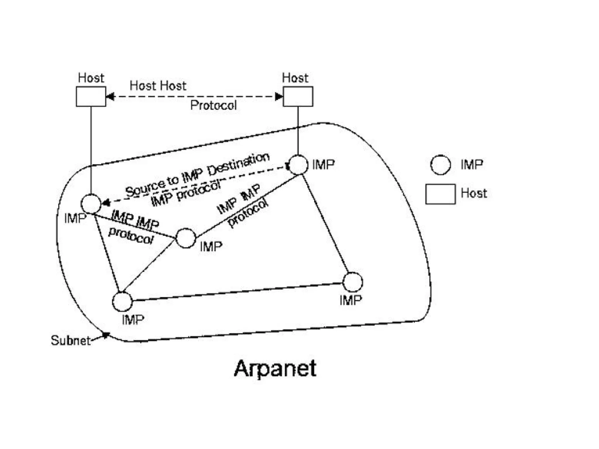
ARPANET used the packet-switching technology to
interconnect four nodes. Hence DoD divided the network into
subnets & host computers. Subnet would consist of
minicomputers called “Interface Message Processors” (IMPs)
connected by transmission lines. For high reliability, each
IMP would be connected to atleast 2 IMPs.
140.
ARPANET wasintroduced in the year 1969 by Advanced
Research Projects Agency (ARPA) of US Department of
Defense.
In the 1970s, ARPANET initially connected only a few sites in
several metropolitan areas of Boston, San Francisco, and Los
Angeles. Then ARPANET gradually developed into a highly
de-urbanized and decentralized communications network,
connecting remote centers and military bases in the United
States.
Characteristics of ARPANET :
1.It is basically a type of WAN.
2.It used concept of Packet Switching Network.
3.It used Interface Message Processors(IMPs) for sub-netting.
4.ARPANETs software was split into two parts- a host and a
subnet.
142.
Advantages of ARPANET:
• ARPANET allowed remote login.
• Transfer of files becomes a part of FTP.
• It uses host-to-host protocol called as NCP (network
control protocol)
• It uses packet switching to send data.
Disadvantages
• Connection to non-system network architecture networks
was difficult.
• Path between the pairs of nodes has to be redesigned and
it has to be stored centrally.
143.
INTERNET
The Internetis the network of networks and the network
allows to exchange of data between two or more computers.
The internet is a type of network and called network of
networks.
The Internet is a way of transporting information between
devices.
Accessible in a variety of ways.
Network protocols are used to transport data.
The internet is a collection of interconnected devices which
are spread across the globe.
It is a network of networks that consist of public, private,
public, sales, finance, academic, business and government
networks.
144.
History of theInternet
Here, are important milestones from the history of the
Internet:
• In 1982 the Internet Protocol (TCP/IP) was standardized.
• In 1990, the World Wide Web introduced.
• In 1995, mainstream Search Engine Yahoo was created.
• In recent time, the Internet covers a large part of the globe
and growing exponentially.
145.
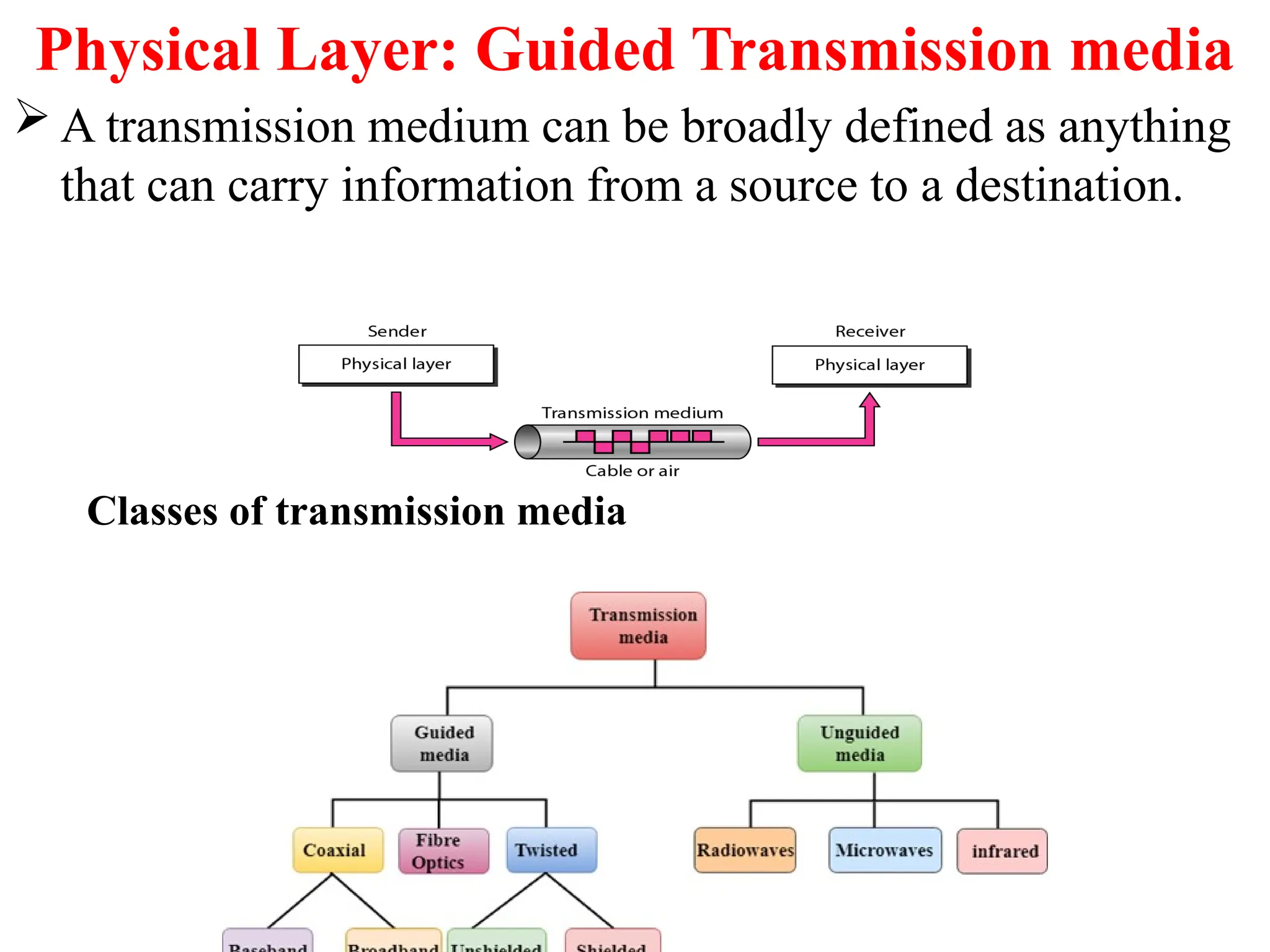
Physical Layer: GuidedTransmission media
A transmission medium can be broadly defined as anything
that can carry information from a source to a destination.
Classes of transmission media
146.
1. Guided Media
It is defined as the physical medium through which the
signals are transmitted. It is also known as Bounded media.
It include Twisted-Pair Cable, Coaxial Cable, and Fibre-
Optic Cable.
A signal travelling along any of these media is directed and
contained by the physical limits of the medium.
Twisted-pair and coaxial cable use metallic (copper)
conductors that accept and transport signals in the form of
electric current.
Optical fibre is a cable that accepts and transports signals
in the form of light.
147.
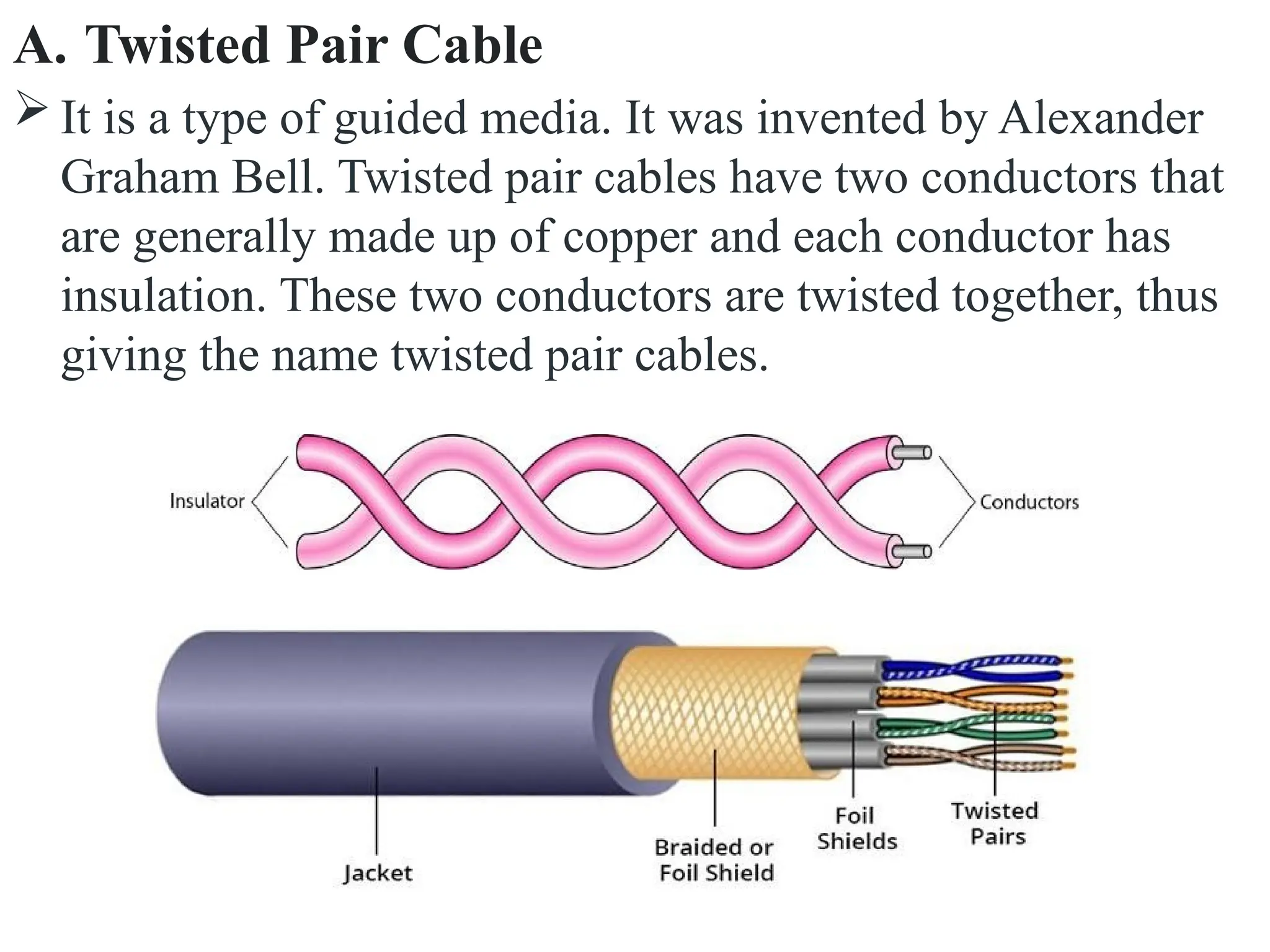
A. Twisted PairCable
It is a type of guided media. It was invented by Alexander
Graham Bell. Twisted pair cables have two conductors that
are generally made up of copper and each conductor has
insulation. These two conductors are twisted together, thus
giving the name twisted pair cables.
148.
A twisted pairconsists of two conductors(normally
copper), each with its own plastic insulators, twisted
together. One of these wires is used to carry signals
to the receiver, and the other is used only as ground
reference. The receiver uses the difference between
the two.
The noise or crosstalk in the two parallel
conductors is high but this is greatly reduced in
twisted pair cables due to the twisting characteristic.
149.
In the firsttwist, one conductor is near to noise
source and the other is far from the source but in the
next twist the reverse happens and the resultant
noise is very less and hence the balance in signal
quality is maintained and the receiver receives very
less noise. The quality of signal in twisted pair
cables greatly depends upon the number of twists
per unit length of the cable.
150.
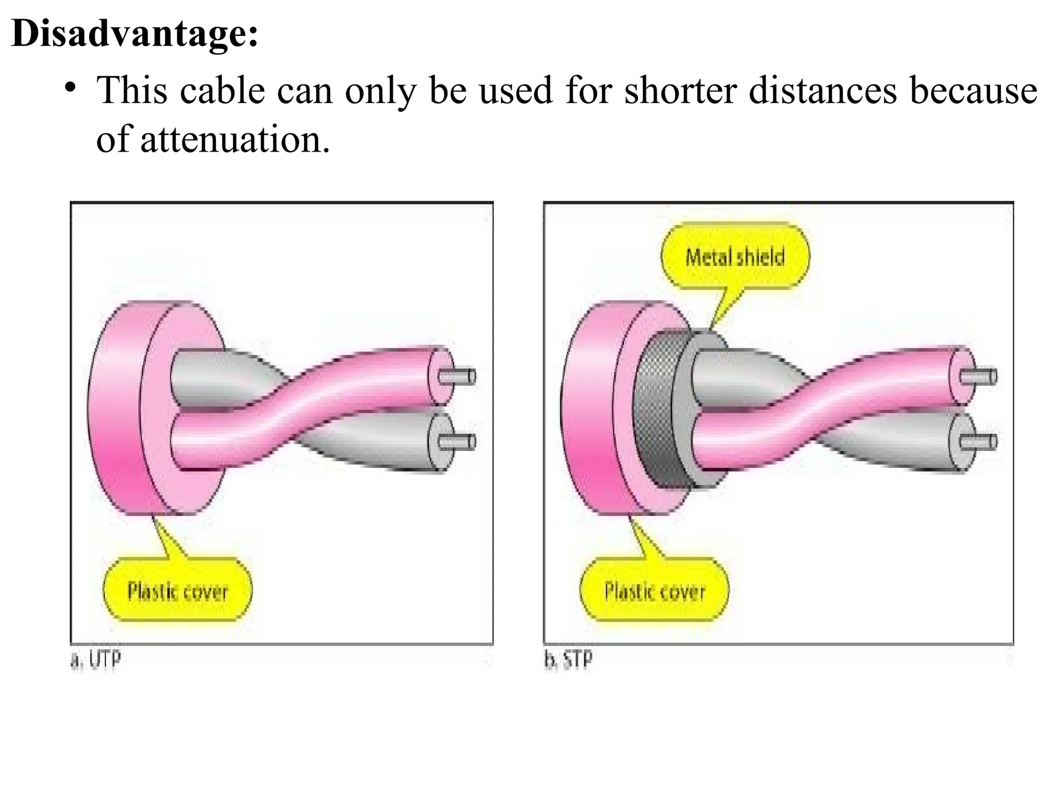
Twisted Pair Cablesare two types :
1. Unshielded Twisted Pair Cables (UTP) :
An unshielded twisted pair is widely used in
telecommunication.
Advantages Of Unshielded Twisted Pair:
• It is cheap.
• Installation of the unshielded twisted pair is easy.
• It can be used for high-speed LAN.
2. Shielded twistedpair(STP) cable:
This type of cable consists of a special jacket (a copper braid
covering or a foil shield) to block external interference and
that allows the higher transmission rate.
Advantages Of Shielded Twisted Pair:
An installation of STP is easy.
It has higher capacity as compared to unshielded twisted
pair cable.
It has a higher attenuation.
It is shielded that provides the higher data transmission
rate.
153.
Disadvantages
It is moreexpensive as compared to UTP and coaxial
cable.
It has a higher attenuation rate.
154.
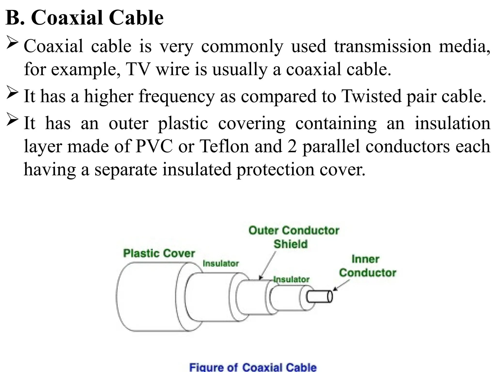
B. Coaxial Cable
Coaxial cable is very commonly used transmission media,
for example, TV wire is usually a coaxial cable.
It has a higher frequency as compared to Twisted pair cable.
It has an outer plastic covering containing an insulation
layer made of PVC or Teflon and 2 parallel conductors each
having a separate insulated protection cover.
155.
Coaxial cable isof two types:
1. Baseband transmission: It is defined as the process of
transmitting a single signal at high speed.
2. Broadband transmission: It is defined as the process of
transmitting multiple signals simultaneously.
Advantages Of Coaxial cable:
• The data can be transmitted at high speed.
• It has better shielding as compared to twisted pair cable.
• It provides higher bandwidth.
• Coaxial cable was widely used in analog telephone
networks, digital telephone networks.
• Cable TV networks also use coaxial cables.
Disadvantages Of Coaxial cable:
• It is more expensive as compared to twisted pair cable.
• Single cable failure can disrupt the entire network
156.
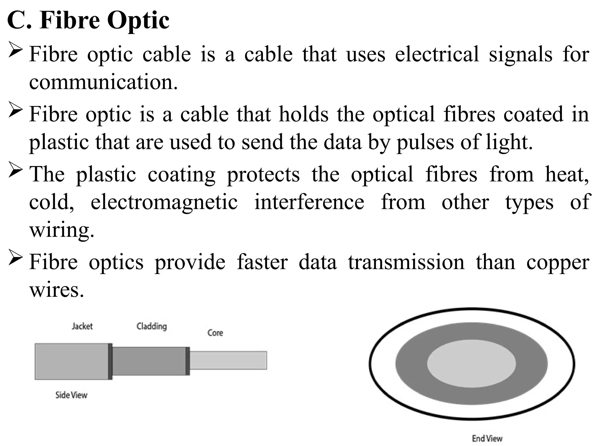
C. Fibre Optic
Fibre optic cable is a cable that uses electrical signals for
communication.
Fibre optic is a cable that holds the optical fibres coated in
plastic that are used to send the data by pulses of light.
The plastic coating protects the optical fibres from heat,
cold, electromagnetic interference from other types of
wiring.
Fibre optics provide faster data transmission than copper
wires.
157.
Core: The opticalfibre consists of a narrow strand of glass or
plastic known as a core. A core is a light transmission area of
the fibre. The more area of the core, the more light will be
transmitted into the fibre.
Cladding: The concentric layer of glass is known as cladding.
The main functionality of the cladding is to provide the lower
refractive index at the core interface as to cause the reflection
within the core so that the light waves are transmitted through
the fibre.
Jacket: The protective coating consisting of plastic is known
as a jacket. The main purpose of a jacket is to preserve the
fibre strength, absorb shock and extra fibre protection.
158.
Advantages of fibreoptic cable:
• Greater Bandwidth: The fibre optic cable provides more
bandwidth as compared copper. Therefore, the fibre optic carries
more data as compared to copper cable.
• Faster speed: Fibre optic cable carries the data in the form of
light. This allows the fibre optic cable to carry the signals at a
higher speed.
• Longer distances: The fibre optic cable carries the data at a longer
distance as compared to copper cable.
• Better reliability: The fibre optic cable is more reliable than the
copper cable as it is immune to any temperature changes while it
can cause obstruct in the connectivity of copper cable.
Disadvantages:
• Difficult to install and maintain
• High cost
159.
2. UnGuided Transmission
It is also referred to as Wireless or Unbounded transmission
media. No physical medium is required for the transmission
of electromagnetic signals.
Features:
The signal is broadcasted through air
Less Secure
Used for larger distances
There are 3 types of Signals transmitted through unguided
media:
160.
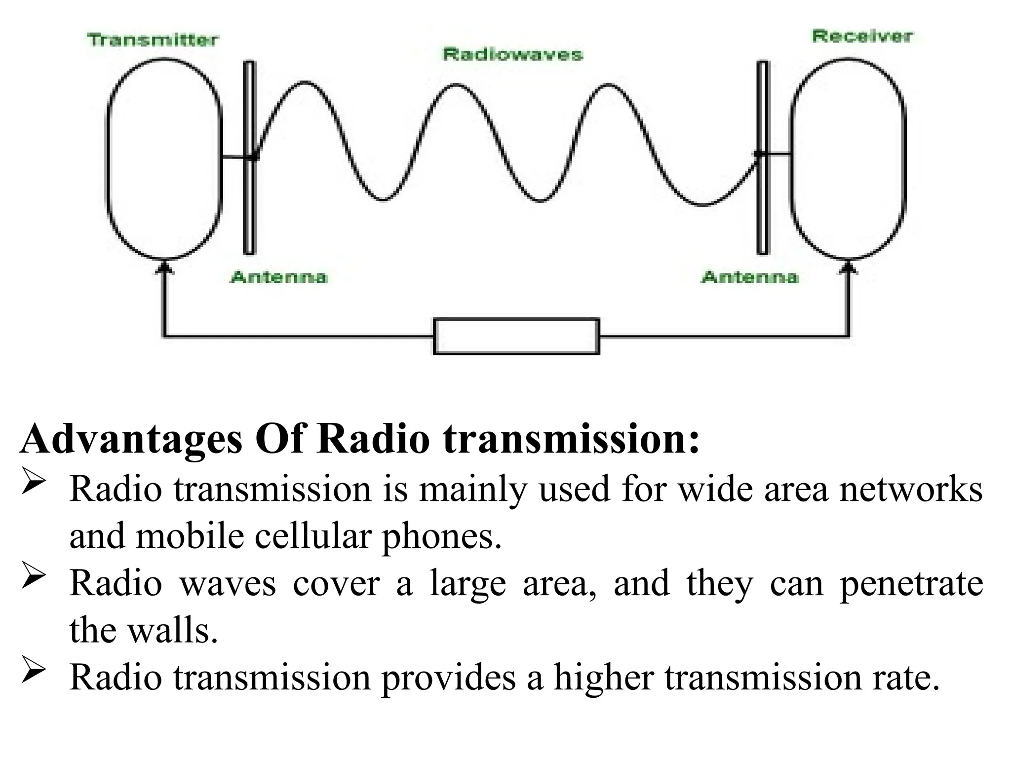
A. Radio waves
Radio waves are the electromagnetic waves that are
transmitted in all the directions of free space.
Radio waves use omnidirectional antennas that send out
signals in all directions. Based on the wavelength, strength,
and the purpose of transmission.
The range in frequencies of radio waves is from 3Khz to 1
khz.
In the case of radio waves, the sending and receiving antenna
are not aligned, i.e., the wave sent by the sending antenna can
be received by any receiving antenna.
A Radio wave is useful for multicasting when there is one
sender and many receivers.
An FM radio, television, cordless phones are examples of
a radio wave.
161.
Advantages Of Radiotransmission:
Radio transmission is mainly used for wide area networks
and mobile cellular phones.
Radio waves cover a large area, and they can penetrate
the walls.
Radio transmission provides a higher transmission rate.
162.
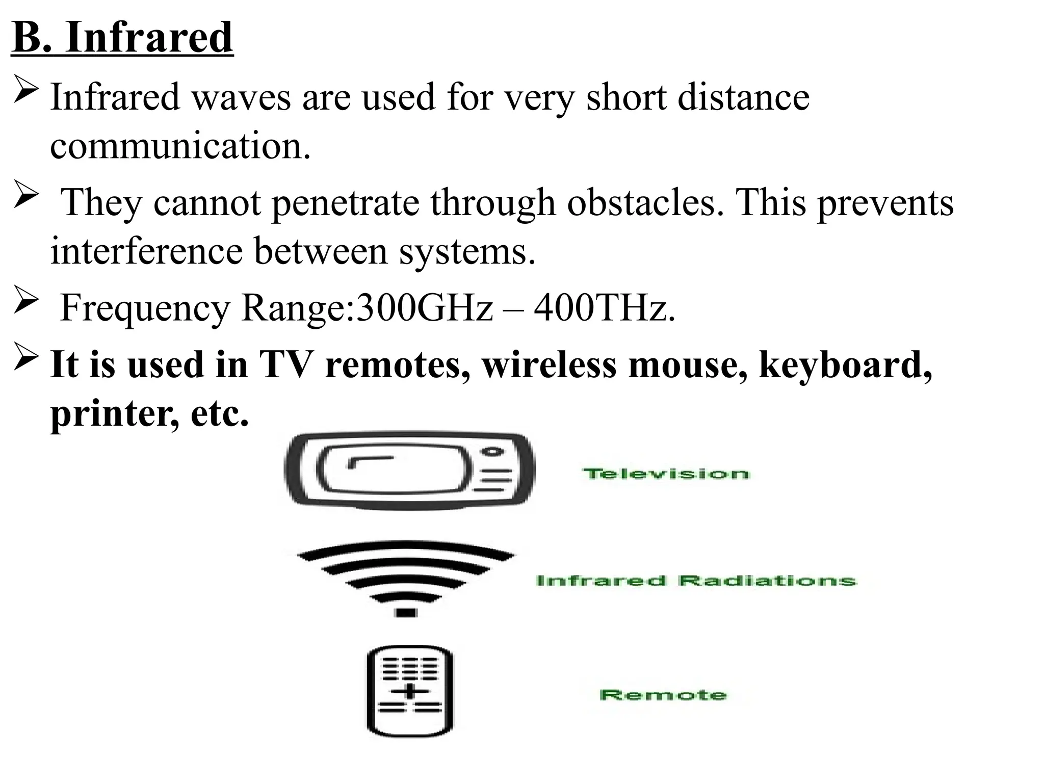
B. Infrared
Infraredwaves are used for very short distance
communication.
They cannot penetrate through obstacles. This prevents
interference between systems.
Frequency Range:300GHz – 400THz.
It is used in TV remotes, wireless mouse, keyboard,
printer, etc.
163.
Advantages:
It supportshigh bandwidth, and hence the data rate will be
very high.
Infrared waves cannot penetrate the walls. Therefore, the
infrared communication in one room cannot be interrupted
by the nearby rooms.
An infrared communication provides better security with
minimum interference.
Infrared communication is unreliable outside the building
because the sun rays will interfere with the infrared waves.
164.
C. Microwaves:
Itis a line of sight transmission i.e. the sending and
receiving antennas need to be properly aligned with each
other.
The distance covered by the signal is directly proportional
to the height of the antenna.
Frequency Range:1GHz – 300GHz.
These are majorly used for mobile phone
communication and television distribution.
165.
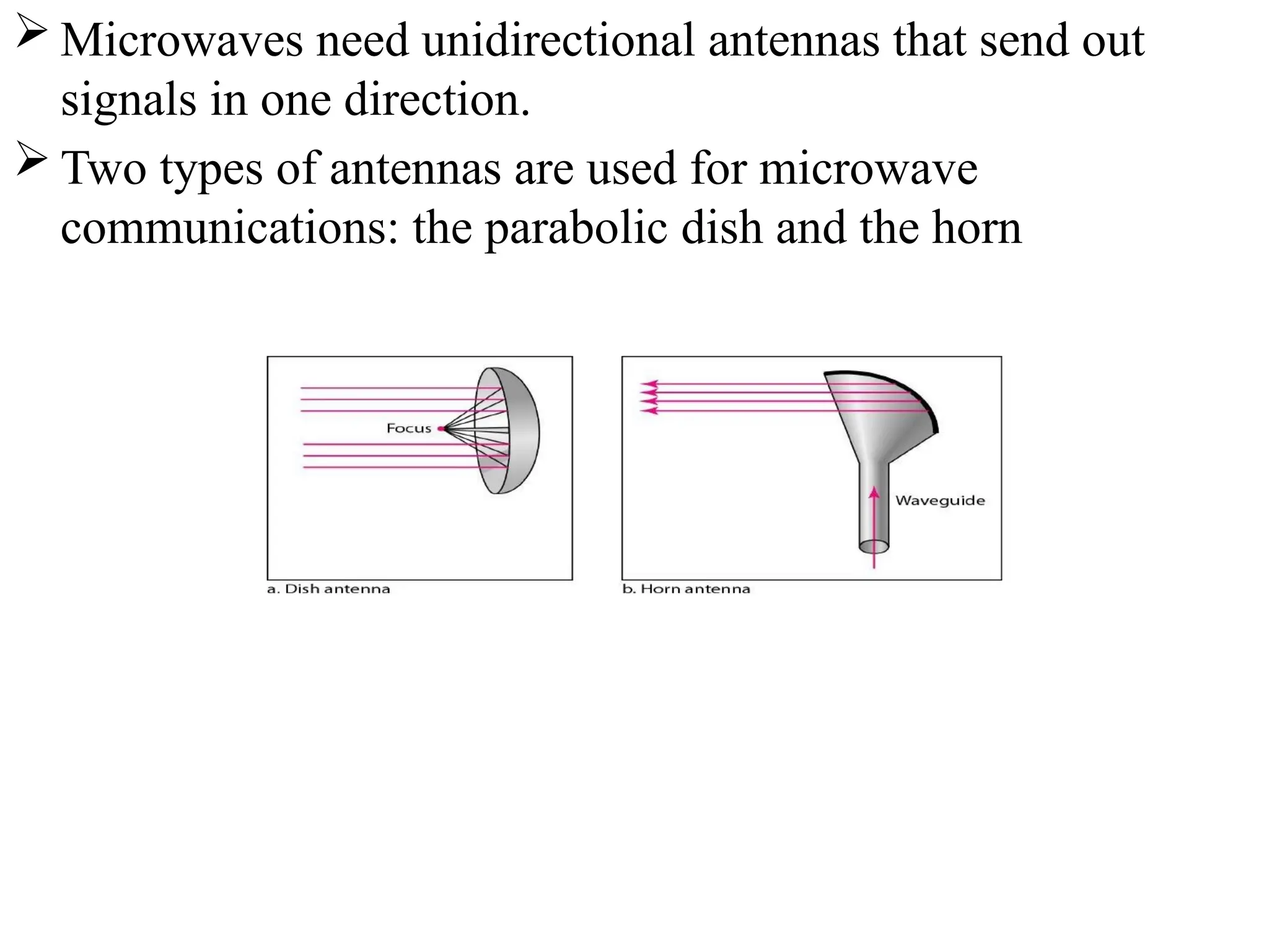
Microwaves needunidirectional antennas that send out
signals in one direction.
Two types of antennas are used for microwave
communications: the parabolic dish and the horn