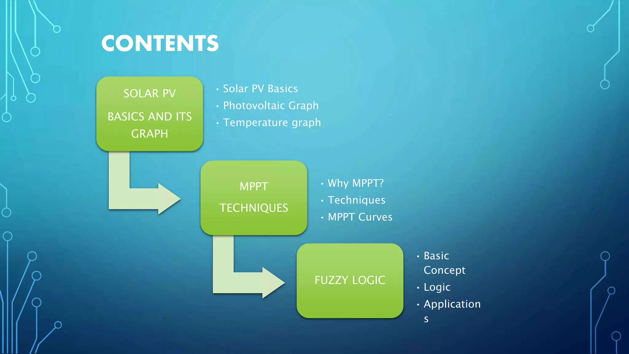
HARNESSING SOLAR ENERGY
THROUGH MPPT BASED CONTROL SYSTEM
USING FUZZY LOGIC
Presented By:
1. Mohd. Shadab Khan
2. Mohd. Wasim Khan
3. Mazir Abbasi
Supervised By:
Mr. Abrar Ahmad
CONTENTS
SOLAR PV
BASICS AND ITS
GRAPH
• Solar PV Basics
• Photovoltaic Graph
• Temperature graph
MPPT
TECHNIQUES
• Why MPPT?
• Techniques
• MPPT Curves
FUZZY LOGIC
• Basic
Concept
• Logic
• Application
s
Solar Photovoltaic &
PHOTOVOLTAIC
By: Mohd. Wasim
Khan
INTRODUCTION
TO
INSIDE A SOLAR PV CELL
An ideal solar cell can be considered as a current source.
The current produced is proportional to solar irradiation falling on it.
A typical cell produces about 0.5 V to 1V.
Source: http://www.researchgate.net/publication/261132099_systems
Equations Involved
SOLAR CELL , MODULE & ARRAYS
Source: http://en.wikipedia.org/wiki/PV
Solar module
PV Array
SOLAR MODULE IN SERIES & PARALLEL
Source: ieeexplore.org/pv_basics_01.pdf
GENERIC I-V CURVE OF PV MODULE
Source: ieeexplore.org/pv_basics_01.pdf
P-V& I-V CURVE OF A SOLAR
MODULE
Source: http://en.wikipedia.org/wiki/PV
OPERATING
POINT
Source: http://en.wikipedia.org/wiki/PV
The point at which PV Module Operates
TEMPERATURE AND IRRADIANCE
EFFECT
Source: ieeexplore.org
1. With Increase of Temperature Voc decreases & corresponding Pout decreases.
2. With Increase of Irradiance Voc increases hence increase in Pout is observed.
SOLAR PARAMETERS
• Short Circuit Current (Isc): Short circuit current is max current produced by a
solar cell when its terminals are short circuited.
• Open Circuit Voltage (Voc): Open circuit voltage is the max voltage that can
be obtained from a solar cell when its terminals are left open. The upper limit of
Voc is decided by the band gap Eg.
• Fill Factor (FF): Fill Factor is defined as ratio of maximum power to the product
of Voc and Isc. FF is 1 for ideal case. Practically its value ranges from 0.8 to
0.89.
• FF = Vm x Im
Voc x Isc
• Efficiency : Efficiency is defined as ratio of maximum power of module to
power delivered by solar irradiance or it can be defined as ratio of product of
Voc ,Isc and FF to solar irradiance .
• Efficiency = Voc x Isc x FF
CONTROLLERBy: Mohd. Shadab Khan
BASICS OF
MPPT
MPPT HARDWARE
Source: amazon.in/mppt_controller
MAXIMUM POWER POINT TRACKING
To automatically find the voltage (VMPP) or current (IMPP) at which a
PV array should operate to obtain the maximum power output
(PMPP)under a given temperature and irradiance.
MPPT TOPOLOGY
Source: ieeexplore.org/pv_basics_01.pdf
CHOICE OF MPPT TECHNIQUE
IMPLEMENTATION
COMPLEXITY
SENSORS
REQUIRED
ABILITY TO
DETECT MULTIPLE
LOCAL MAXIMA
RESPONSE TIME
COST APPLICATION
I-V CURVES FOR DIFFERENT TEMPERATURE AND
IRRADIANCE LEVEL
Source: ieeexplore.org/pv01aop.1.pdf
P-V CURVES FOR DIFFERENT TEMPERATURE AND
IRRADIANCE LEVEL
Source: ieeexplore.org/pv_basics_01.pdf
P-V CURVE FOR
MPPT
Source: ieeexplore.mppt_technique/papers.org
NEED FOR MPPT
Source: http://en.wikipedia.org/wiki/PV
IRRADIANCE & TEMPERATURE VARIATION
LOW CONVERSION EFFICIENCY(9-17%)
TO MAXIMIZE OUTPUT POWER
TO MAXIMIZE THE EFFICIENCY
MPPT TECHNIQUES
MPP
Techniques
Indirect
Fixed Voltage
Method
Fractional Open
Circuit Voltage
Method
Direct
Perturb &
Observe Method
Incremental
Conduction
Method
FIXED VOLTAGE METHOD
Source: http://www.pveducation.org/pvcdrom/mppt
Based on adjusting
the operating voltage
on a seasonal basis
1. Higher MPP during
winters
2. Lower MPP in
summers
Not very accurate , &
accuracy is increased
if irradiance variation
is minimized
FRACTIONAL OPEN CIRCUIT VOLTAGE
METHOD
Source: http://www.pveducation.org/pvcdrom/fc_mpp
Approximation
of VMPP is done
by finding the
open circuit
voltage
Value of K
depends on PV
technology used
and kind of solar
cell used
Not always point
to the MPP, but
only in the
region around
MPP
VMPP=
K*Voc
PERTURB & OBSERVE (P&O)/HILL CLIMBING
METHOD
Source: http://www.pveducation.org/pvcdrom/p&o
Direct measurement
of current, voltage
and power.
Faster and accurate
response
Incrementing the voltage
increases
the power when operating on
the
left of the MPP and decreases
the
power when on the right of
the MPP.
1
2
3
6
5
DRAWBACKS OF P&O METHOD
• Hill climbing and P&O methods can fail under rapidly changing
atmospheric conditions.
• The process is repeated periodically until the MPP is reached.
• The system oscillates about the MPP.
• Smaller perturbation size slows down the MPPT
• If the irradiance fluctuates
and shifts the power curve
within one sampling period,
the operating point will
fluctuate
Source: http://en.wikipedia.org/wiki/PV
INCREMENTAL CONDUCTANCE METHOD
Source: http://file.scirp.org/Html/4-1770016%5Ce05a0b9b-b3dc-49c5-9a11-7d933bb7a3a9.jpg
Based on the fact that slope of
PV:
1. Zero at MPP
2. Negative at right of MPP
3. Positive on left of MPP
.
.
Uses two sensors:
VOLTAGE & CURRENT
SENSORS to sense the
output voltage and current
ALGORITHM works by comparing
the ratio of derivative of
conductance with the
instantaneous conductance
When this instantaneous
conductance equals the
conductance of the solar then MPP
is reached
Logic……… IN MPPT
By: Mazir
Abbasi
IMPLEMENTATION
OF
FUZZY
A QUICK REVIEW
 Definition of fuzzy
 Fuzzy – “not clear, distinct, or precise; blurred”
 Definition of fuzzy logic
 A form of knowledge representation suitable for notions that cannot be
defined precisely, but which depend upon their contexts.
Slowest FastestSlow Fast
Speed=0 Speed=1Speed=0.5 Speed=0.75
FUZZY CONTROLLER IN PV
Artificial intelligent
tool which computes
output based on
expert knowledge.
faster response
using the expert
knowledge and
measured data
base.
FL Algorithm is
chosen for PV
because of its fast
and accurate
response
Fuzzy logic
controller
algorithm is
based on three
steps
1-expert
knowledge, 2-
fuzzification &
inference diagram
3-defuzzification.
FUZZY LOGIC MPPT
CONTROLLER
FUZZIFICATIO
N
INFERENC
E
DEFUZZIFICATI
ON
RULES
Acquisition of data(P,V)
Generate inputs for fuzzy logic control
Apply the fuzzy logic controller and obtain the
proper D value
Buck boost controller
STAR
T
RETUR
N
FUZZY LOGIC FLOWCHART IN
MPPT
HARDWARE MODELLING OF FUZZY IN
MPPT
FUZZIFICATIO
N
INFERENC
E
ENGINE
DEFUZZIFICATI
ON
FUZZY
RULE
BOX
FUZZY LOGIC CONTROLLER
PV
MODEL
BUCK
BOOST
CONVERTE
R
LOAD
FILTERING AND
GENERATION OF
FUZZY INPUT
VARIABLES
PWM
GENERATO
R Duty Ratio Command
REFRENCE
S
[1] Noppadol Khaehintung, Phaophak Sirisuk, and Anatawat Kunakorn, “Grid-connected photovoltaic
system with maximum power point tracking using self-organizing fuzzy logic controller”, IEEE Power
Electronics and Drives Systems, PEDS, Kuala Lumpur, 2005, pp. 517-521.
[2] Huan-Liang Tsai, “Insolation-oriented model of photovoltaic module using MATLAB/SIMULINK”, Solar
Energy 84, 2010, pp. 13181326.
[3] S.Lalouni, D. Rekioua, T. Rekioua, and E. Matagne, “Fuzzy logic control of sand-alone photovoltaic
system with battery storage”, Journal of Power Sources, Volume 193, Issue2, 5 September 2009, pp.
899-907.
[4] V. Salas, E. Olias, A. Barrado, and A. Lazaro, “ Review of the maximum power point tracking algorithms
for stand-alone photovoltaic systems”, Soalr Energy Materials & Solar Cells 90, 2006, pp. 1555-1578.
[5] M.S. Ait Cheikh, C. Larbes, G. F. Tchoketch Kebir, and A. Zerguerras, “Maximum power point tracking
using a fuzzy logic control scheme”, Revue des energies Renouvelables, Vol. 10, 2007, pp. 387-395.
[6] H.J. Möller, ‘Semiconductors for Solar Cells’, Artech House, Inc, Norwood, MA, 1993.
[7] R. Gottschalg, M. Rommel, D.G. Ineld and H. Ryssel, ‘Comparison of Different Methods for the

MPPT using fuzzy logic

  • 1.
    HARNESSING SOLAR ENERGY THROUGHMPPT BASED CONTROL SYSTEM USING FUZZY LOGIC Presented By: 1. Mohd. Shadab Khan 2. Mohd. Wasim Khan 3. Mazir Abbasi Supervised By: Mr. Abrar Ahmad
  • 2.
    CONTENTS SOLAR PV BASICS ANDITS GRAPH • Solar PV Basics • Photovoltaic Graph • Temperature graph MPPT TECHNIQUES • Why MPPT? • Techniques • MPPT Curves FUZZY LOGIC • Basic Concept • Logic • Application s
  • 3.
    Solar Photovoltaic & PHOTOVOLTAIC By:Mohd. Wasim Khan INTRODUCTION TO
  • 4.
    INSIDE A SOLARPV CELL An ideal solar cell can be considered as a current source. The current produced is proportional to solar irradiation falling on it. A typical cell produces about 0.5 V to 1V. Source: http://www.researchgate.net/publication/261132099_systems Equations Involved
  • 5.
    SOLAR CELL ,MODULE & ARRAYS Source: http://en.wikipedia.org/wiki/PV Solar module PV Array
  • 6.
    SOLAR MODULE INSERIES & PARALLEL Source: ieeexplore.org/pv_basics_01.pdf
  • 7.
    GENERIC I-V CURVEOF PV MODULE Source: ieeexplore.org/pv_basics_01.pdf
  • 8.
    P-V& I-V CURVEOF A SOLAR MODULE Source: http://en.wikipedia.org/wiki/PV
  • 9.
  • 10.
    TEMPERATURE AND IRRADIANCE EFFECT Source:ieeexplore.org 1. With Increase of Temperature Voc decreases & corresponding Pout decreases. 2. With Increase of Irradiance Voc increases hence increase in Pout is observed.
  • 11.
    SOLAR PARAMETERS • ShortCircuit Current (Isc): Short circuit current is max current produced by a solar cell when its terminals are short circuited. • Open Circuit Voltage (Voc): Open circuit voltage is the max voltage that can be obtained from a solar cell when its terminals are left open. The upper limit of Voc is decided by the band gap Eg. • Fill Factor (FF): Fill Factor is defined as ratio of maximum power to the product of Voc and Isc. FF is 1 for ideal case. Practically its value ranges from 0.8 to 0.89. • FF = Vm x Im Voc x Isc • Efficiency : Efficiency is defined as ratio of maximum power of module to power delivered by solar irradiance or it can be defined as ratio of product of Voc ,Isc and FF to solar irradiance . • Efficiency = Voc x Isc x FF
  • 12.
    CONTROLLERBy: Mohd. ShadabKhan BASICS OF MPPT
  • 13.
  • 14.
    MAXIMUM POWER POINTTRACKING To automatically find the voltage (VMPP) or current (IMPP) at which a PV array should operate to obtain the maximum power output (PMPP)under a given temperature and irradiance. MPPT TOPOLOGY Source: ieeexplore.org/pv_basics_01.pdf
  • 15.
    CHOICE OF MPPTTECHNIQUE IMPLEMENTATION COMPLEXITY SENSORS REQUIRED ABILITY TO DETECT MULTIPLE LOCAL MAXIMA RESPONSE TIME COST APPLICATION
  • 16.
    I-V CURVES FORDIFFERENT TEMPERATURE AND IRRADIANCE LEVEL Source: ieeexplore.org/pv01aop.1.pdf
  • 17.
    P-V CURVES FORDIFFERENT TEMPERATURE AND IRRADIANCE LEVEL Source: ieeexplore.org/pv_basics_01.pdf
  • 18.
    P-V CURVE FOR MPPT Source:ieeexplore.mppt_technique/papers.org
  • 19.
    NEED FOR MPPT Source:http://en.wikipedia.org/wiki/PV IRRADIANCE & TEMPERATURE VARIATION LOW CONVERSION EFFICIENCY(9-17%) TO MAXIMIZE OUTPUT POWER TO MAXIMIZE THE EFFICIENCY
  • 20.
    MPPT TECHNIQUES MPP Techniques Indirect Fixed Voltage Method FractionalOpen Circuit Voltage Method Direct Perturb & Observe Method Incremental Conduction Method
  • 21.
    FIXED VOLTAGE METHOD Source:http://www.pveducation.org/pvcdrom/mppt Based on adjusting the operating voltage on a seasonal basis 1. Higher MPP during winters 2. Lower MPP in summers Not very accurate , & accuracy is increased if irradiance variation is minimized
  • 22.
    FRACTIONAL OPEN CIRCUITVOLTAGE METHOD Source: http://www.pveducation.org/pvcdrom/fc_mpp Approximation of VMPP is done by finding the open circuit voltage Value of K depends on PV technology used and kind of solar cell used Not always point to the MPP, but only in the region around MPP VMPP= K*Voc
  • 23.
    PERTURB & OBSERVE(P&O)/HILL CLIMBING METHOD Source: http://www.pveducation.org/pvcdrom/p&o Direct measurement of current, voltage and power. Faster and accurate response Incrementing the voltage increases the power when operating on the left of the MPP and decreases the power when on the right of the MPP. 1 2 3 6 5
  • 24.
    DRAWBACKS OF P&OMETHOD • Hill climbing and P&O methods can fail under rapidly changing atmospheric conditions. • The process is repeated periodically until the MPP is reached. • The system oscillates about the MPP. • Smaller perturbation size slows down the MPPT • If the irradiance fluctuates and shifts the power curve within one sampling period, the operating point will fluctuate Source: http://en.wikipedia.org/wiki/PV
  • 25.
    INCREMENTAL CONDUCTANCE METHOD Source:http://file.scirp.org/Html/4-1770016%5Ce05a0b9b-b3dc-49c5-9a11-7d933bb7a3a9.jpg Based on the fact that slope of PV: 1. Zero at MPP 2. Negative at right of MPP 3. Positive on left of MPP . . Uses two sensors: VOLTAGE & CURRENT SENSORS to sense the output voltage and current ALGORITHM works by comparing the ratio of derivative of conductance with the instantaneous conductance When this instantaneous conductance equals the conductance of the solar then MPP is reached
  • 26.
    Logic……… IN MPPT By:Mazir Abbasi IMPLEMENTATION OF FUZZY
  • 27.
    A QUICK REVIEW Definition of fuzzy  Fuzzy – “not clear, distinct, or precise; blurred”  Definition of fuzzy logic  A form of knowledge representation suitable for notions that cannot be defined precisely, but which depend upon their contexts. Slowest FastestSlow Fast Speed=0 Speed=1Speed=0.5 Speed=0.75
  • 28.
    FUZZY CONTROLLER INPV Artificial intelligent tool which computes output based on expert knowledge. faster response using the expert knowledge and measured data base. FL Algorithm is chosen for PV because of its fast and accurate response Fuzzy logic controller algorithm is based on three steps 1-expert knowledge, 2- fuzzification & inference diagram 3-defuzzification.
  • 29.
  • 30.
    Acquisition of data(P,V) Generateinputs for fuzzy logic control Apply the fuzzy logic controller and obtain the proper D value Buck boost controller STAR T RETUR N FUZZY LOGIC FLOWCHART IN MPPT
  • 31.
    HARDWARE MODELLING OFFUZZY IN MPPT FUZZIFICATIO N INFERENC E ENGINE DEFUZZIFICATI ON FUZZY RULE BOX FUZZY LOGIC CONTROLLER PV MODEL BUCK BOOST CONVERTE R LOAD FILTERING AND GENERATION OF FUZZY INPUT VARIABLES PWM GENERATO R Duty Ratio Command
  • 32.
    REFRENCE S [1] Noppadol Khaehintung,Phaophak Sirisuk, and Anatawat Kunakorn, “Grid-connected photovoltaic system with maximum power point tracking using self-organizing fuzzy logic controller”, IEEE Power Electronics and Drives Systems, PEDS, Kuala Lumpur, 2005, pp. 517-521. [2] Huan-Liang Tsai, “Insolation-oriented model of photovoltaic module using MATLAB/SIMULINK”, Solar Energy 84, 2010, pp. 13181326. [3] S.Lalouni, D. Rekioua, T. Rekioua, and E. Matagne, “Fuzzy logic control of sand-alone photovoltaic system with battery storage”, Journal of Power Sources, Volume 193, Issue2, 5 September 2009, pp. 899-907. [4] V. Salas, E. Olias, A. Barrado, and A. Lazaro, “ Review of the maximum power point tracking algorithms for stand-alone photovoltaic systems”, Soalr Energy Materials & Solar Cells 90, 2006, pp. 1555-1578. [5] M.S. Ait Cheikh, C. Larbes, G. F. Tchoketch Kebir, and A. Zerguerras, “Maximum power point tracking using a fuzzy logic control scheme”, Revue des energies Renouvelables, Vol. 10, 2007, pp. 387-395. [6] H.J. Möller, ‘Semiconductors for Solar Cells’, Artech House, Inc, Norwood, MA, 1993. [7] R. Gottschalg, M. Rommel, D.G. Ineld and H. Ryssel, ‘Comparison of Different Methods for the