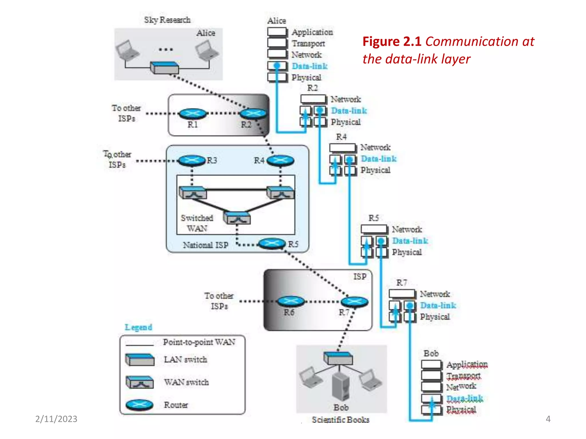
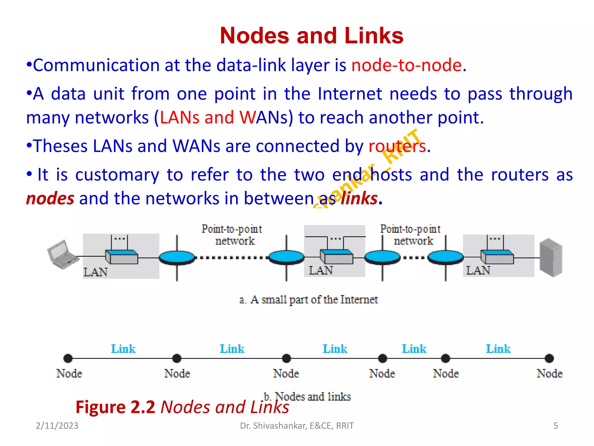
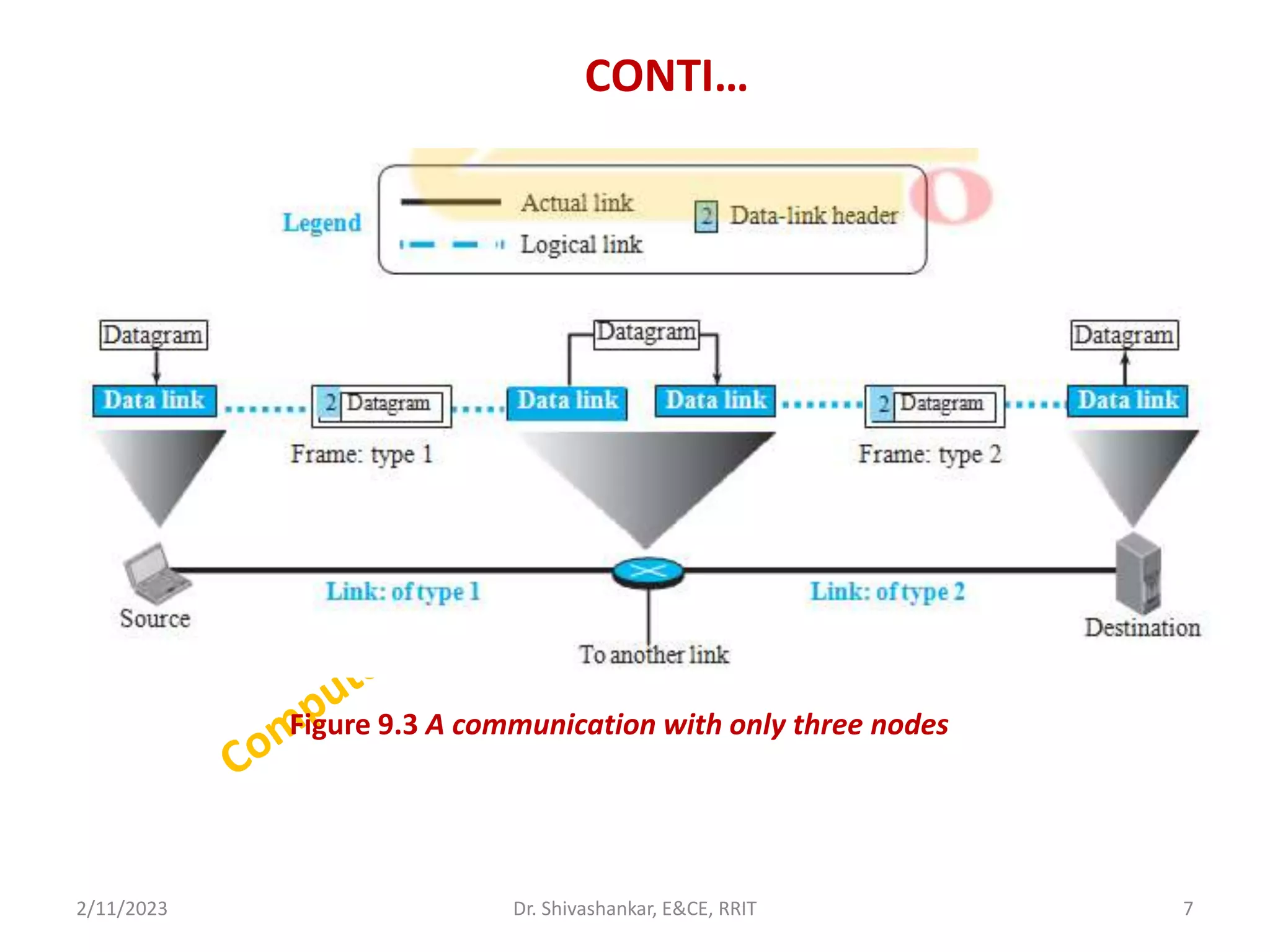
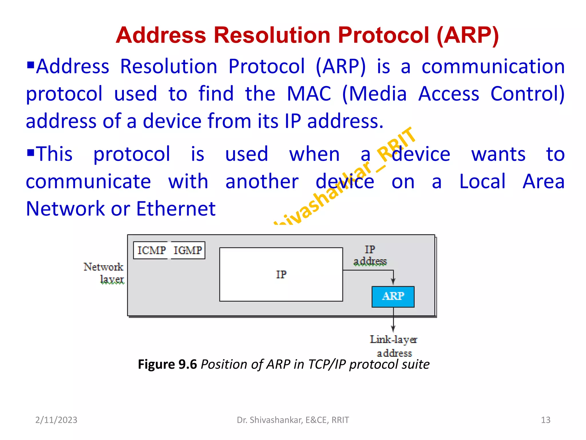
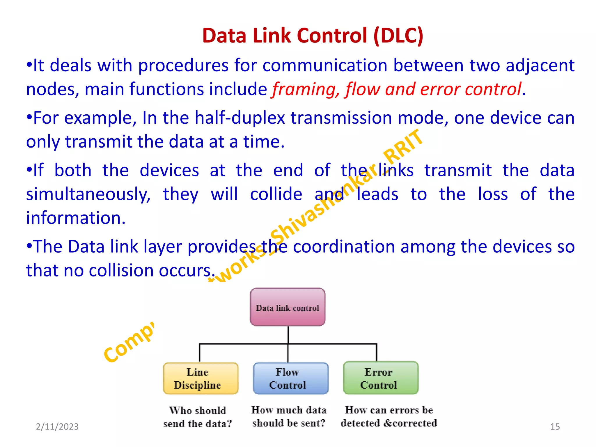
COMPUTER NETWORK
(18EC71)
Dr. Shivashankar
Professor
Department of Electronics & Communication
Engineering
RRIT, Bangalore
2/11/2023 1
Dr. Shivashankar, E&CE, RRIT
Course Outcomes
After Completion of the course, student will be able to
Understand the concepts of networking thoroughly.
Describe the various network architectures
Identify the protocols and services of different layers
Distinguish the basic network configurations and
standards associated with each network models.
Analyze a simple network and measurements of its
parameters.
Text Book:
Data Communications and Networking , Forouzan, 5th
Edition, McGraw Hill, 2016 ISBN: 1-25-906475-3
2/11/2023 2
Dr. Shivashankar, E&CE, RRIT
MODULE-2 DATA LINK LAYER
Introduction
•Moving of data into and out of a physical link in a network.
•Data bits are encoded, decoded and organized in the data link
layer, before they are transported as frames between two
adjacent nodes on the same LAN or WAN.
•Also determines how devices recover from collisions that may
occur when nodes attempt to send frames at the same time.
•It ensures an initial connection will be set up, divides output
data into data frames and handles the acknowledgements
from a receiver that the data arrived successfully.
2/11/2023 3
Dr. Shivashankar, E&CE, RRIT
2/11/2023 4
Dr. Shivashankar, E&CE, RRIT
Figure 2.1 Communication at
the data-link layer
Nodes and Links
•Communication at the data-link layer is node-to-node.
•A data unit from one point in the Internet needs to pass through
many networks (LANs and WANs) to reach another point.
•Theses LANs and WANs are connected by routers.
• It is customary to refer to the two end hosts and the routers as
nodes and the networks in between as links.
2/11/2023 5
Dr. Shivashankar, E&CE, RRIT
Figure 2.2 Nodes and Links
Services
•The data-link layer is located between the physical and
the network layers.
•The data- link layer provides services to the network
layer; it receives services from the physical layer.
•The duty scope of the data-link layer is node-to-node.
When a packet is travelling in the Internet, the data-link
layer of a node (host or router) is responsible for
delivering a datagram to the next node in the path.
•For this purpose, the data-link layer of the sending node
needs to encapsulate the datagram received from the
network in a frame, and receiving node needs to
decapsulate the datagram from the frame.
2/11/2023 6
Dr. Shivashankar, E&CE, RRIT
CONTI…
2/11/2023 7
Dr. Shivashankar, E&CE, RRIT
Figure 9.3 A communication with only three nodes
Two Categories of Links
•Data link layers uses the capacity of media and link.
•It has two links:
•point-to-point link and
• broadcast link.
•In a point-to-point link, the link is dedicated to the two
devices;
•In a broadcast link, the link is shared between several pairs of
devices.
•Example, when two friends use the traditional home phones
to chat, they are using a point-to-point link.
•When the same two friends use their cellular phones, they
are using a broadcast link (air is shared among many cell
phone users).
2/11/2023 8
Dr. Shivashankar, E&CE, RRIT
Two Sub-layers
There are two sublayers of data link layers:
Data Link Control (DLC) and
Media Access Control (MAC)
The data link control sublayer deals with all issues common to both
point-to-point and broadcast links;
the media access control sub- layer deals only with issues specific
to broadcast links.
2/11/2023 9
Dr. Shivashankar, E&CE, RRIT
Figure 9.4 Dividing the data-link layer into two sublayers
LINK-LAYER ADDRESSING
A link-layer address is sometimes called a link address, sometimes
a physical address, and some- times a MAC address.
Since a link is controlled at the data-link layer, the addresses need
to belong to the data-link layer.
When a datagram passes from the network layer to the data-link
layer, the datagram will be encapsulated in a frame and two data-
link addresses are added to the frame header.
These two addresses are changed every time the frame moves
from one link to another.
2/11/2023 10
Dr. Shivashankar, E&CE, RRIT
CONTI…
2/11/2023 11
Dr. Shivashankar, E&CE, RRIT
Figure 9.5 IP addresses and link-layer addresses in a small internet
Types of Addresses
1. Unicast Address:
•Each host or each interface of a router is assigned a unicast
address. Unicasting means one-to-one communication.
•A frame with a unicast address destination is destined only for one
entity in the link.
•Example: A3:34:45:11:92:F1
2. Multicast Address:
Multicasting means one-to-many communication.
Example: A2:34:45:11:92:F1
3. Broadcast Address:
•Broadcasting means one-to-all communication. A frame with a
destination broadcast address is sent to all entities in the link.
•Example: FF:FF:FF:FF:FF:FF
2/11/2023 12
Dr. Shivashankar, E&CE, RRIT
Address Resolution Protocol (ARP)
Address Resolution Protocol (ARP) is a communication
protocol used to find the MAC (Media Access Control)
address of a device from its IP address.
This protocol is used when a device wants to
communicate with another device on a Local Area
Network or Ethernet
2/11/2023 13
Dr. Shivashankar, E&CE, RRIT
Figure 9.6 Position of ARP in TCP/IP protocol suite
Cont..
Anytime a node has an IP datagram to send to another node in a
link, it has the IP address of the receiving node.
The source host knows the IP address of the default router.
Each router except the last one in the path gets the IP address of
the next router by using its for- warding table.
The last router knows the IP address of the destination host.
The ARP protocol is one of the auxiliary protocols defined in the
network layer.
ARP accepts an IP address from the IP protocol, maps the address
to the corresponding link-layer address, and passes it to the data-
link layer.
2/11/2023 14
Dr. Shivashankar, E&CE, RRIT
Data Link Control (DLC)
•It deals with procedures for communication between two adjacent
nodes, main functions include framing, flow and error control.
•For example, In the half-duplex transmission mode, one device can
only transmit the data at a time.
•If both the devices at the end of the links transmit the data
simultaneously, they will collide and leads to the loss of the
information.
•The Data link layer provides the coordination among the devices so
that no collision occurs.
2/11/2023 15
Dr. Shivashankar, E&CE, RRIT
Framing
•Frame is a Unit of data.
•The destination address defines where the packet is to
go; the sender address helps the recipient acknowledge
the receipt.
•Although the whole message could be packed in one
frame,
•It provides a way for a sender to transmit a set of bits
that are meaningful to the receiver.
Types of Frame Size
•Frames can be of fixed or variable size.
•In fixed-size framing, there is no need for defining the
boundaries of the frames- called cells
2/11/2023 16
Dr. Shivashankar, E&CE, RRIT
Character-Oriented Framing
•In character-oriented (or byte-oriented) framing, data to be carried
are 8-bit characters from a coding system such as ASCII.
•The header, which normally carries the source and destination
addresses and other control information, and the trailer, which
carries error detection redundant bits, are also multiples of 8 bits.
•The flag, composed of protocol-dependent special characters,
signals the start or end of a frame.
2/11/2023 17
Dr. Shivashankar, E&CE, RRIT
Figure 11.1 A frame in a character-oriented protocol
CONTI…
2/11/2023 18
Dr. Shivashankar, E&CE, RRIT
Figure 11.2 Byte stuffing and unstuffing
Bit-Oriented Framing
•In bit-oriented framing, the data section of a frame is a sequence
of bits to be interpreted by the upper layer as text, graphic, audio,
video, and so on.
•Most protocols use a special 8-bit pattern flag, 01111110, as the
delimiter to define the beginning and the end of the frame.
2/11/2023 19
Dr. Shivashankar, E&CE, RRIT
Figure 11.3 A frame in a bit-oriented protocol
CONTI…
2/11/2023 20
Dr. Shivashankar, E&CE, RRIT
Figure 11.4: Bit stuffing and unstuffing
Flow Control
•It is a technique that generally observes the proper flow
of data from sender to receiver.
•It is very essential because it is possible for sender to
transmit data or information at very fast rate and hence
receiver can receive this information and process it.
•Flow control is actually set of procedures that explains
sender about how much data or frames it can transfer or
transmit before data overwhelms receiver.
•The receiving device also contains only limited amount of
speed and memory to store data.
2/11/2023 21
Dr. Shivashankar, E&CE, RRIT
CONTI…
2/11/2023 22
Dr. Shivashankar, E&CE, RRIT
Figure 2.6: Procedure of Flow Control
BUFFER
•A buffer is a set of memory locations that can hold packets at the
sender and receiver.
•It is used when moving data between processes within a computer.
•Majority of buffers are implemented in software.
•Buffers are generally used when there is a difference between the
rate at which data is received and the rate at which it can be
processed.
•If we remove buffers, then either we will have data loss, or we will
have lower bandwidth utilization.
•When the buffer of the receiving data-link layer is full, it informs
the sending data-link layer to stop pushing frames.
2/11/2023 23
Dr. Shivashankar, E&CE, RRIT
ERROR CONTROL
 Error control is basically process in data link layer of detecting or
identifying and re-transmitting data frames that might be lost or
corrupted during transmission.
In both of these cases, receiver or destination does not receive
correct data-frame and sender or source does not even know
anything about any such loss regarding data frames.
The Data-link layer follows technique known as re-transmission of
frames to detect or identify transit errors and also to take necessary
actions that are required to reduce or remove such errors.
Each and every time an effort is detected during transmission,
particular data frames retransmitted and this process is known as
Automatic Repeat Request (ARQ).
2/11/2023 24
Dr. Shivashankar, E&CE, RRIT
DATA LINK LAYER PROTOCOLS
Traditionally four protocols have been defined for the data-link
layer to deal with flow and error control.
1. Simple
2. Stop-and-Wait
3. Go-Back-N and
4. Selective-Repeat.
2/11/2023 25
Dr. Shivashankar, E&CE, RRIT
SIMPLE PROTOCOLS
•The simplest protocol is a data link layer protocol used for noiseless
channels.
•The simplest protocol is also known as the Elementary Data Link
Protocol.
•As the simplest protocol is used in noiseless channels, it has no
error control and no flow control.
•In the simplest protocol, receiver is always ready to handle any
frames coming from the sender immediately.
•The simplest protocol is a unidirectional protocol in which the data
frames travel in only one direction from the sender to the receiver.
•The processing time of the simplest protocol is very short.
•Hence it can be neglected.
2/11/2023 26
Dr. Shivashankar, E&CE, RRIT
CONTI…
2/11/2023 27
Dr. Shivashankar, E&CE, RRIT
Figure 11.7 Simple protocol
Figure 11.8 FSMs for the simple protocol
CONTI…
2/11/2023 28
Dr. Shivashankar, E&CE, RRIT
Figure 11.9: Flow diagram of Simplest Protocol
Stop-and-Wait Protocol
It uses both flow and error control.
The sender sends one frame at a time and waits for an acknowledgment before
sending the next one.
To detect corrupted frames, we need to add a CRC to each data frame.
When a frame arrives at the receiver site, it is checked. If its CRC is incorrect, the
frame is corrupted and silently discarded.
Every time the sender sends a frame, it starts a timer.
If an acknowledgment arrives before the timer expires, the timer is stopped and
the sender sends the next frame.
If the timer expires, the sender resends the previous frame, assuming that the
frame was either lost or corrupted.
This means that the sender needs to keep a copy of the frame until its
acknowledgment arrives.
When the corresponding acknowledgment arrives, the sender discards the copy
and sends the next frame if it is ready.
2/11/2023 29
Dr. Shivashankar, E&CE, RRIT
CONTI…
Note that only one frame and one acknowledgment can be in the channels at any
time.
This means that the sender needs to keep a copy of the frame until its
acknowledgment arrives
2/11/2023 30
Dr. Shivashankar, E&CE, RRIT
Figure 2.10 Stop-and-Wait protocol
CONTI…
2/11/2023 31
Dr. Shivashankar, E&CE, RRIT
Figure 11.11 FSM for the Stop-and-Wait protocol
CONTI…
Sender States
The sender is initially in the ready state, but it can move between the ready
and blocking state.
❑ Ready State: When the sender is in this state, it is only waiting for a packet from
the network layer. If a packet comes from the network layer, the sender creates a
frame, saves a copy of the frame, starts the only timer and sends the frame.
❑ Blocking State: When the sender is in this state, three events can occur:
a. If a time-out occurs, the sender resends the saved copy of the frame
and restartsthe timer.
b. If a corrupted ACK arrives, it is discarded.
c. If an error-free ACK arrives, the sender stops the timer and discards
the saved copy of the frame. It then moves to the ready state.
Receiver
The receiver is always in the ready state. Two events may occur:
a. If an error-free frame arrives, the message in the frame is delivered to the net-
work layer and an ACK is sent.
b. If a corrupted frame arrives, the frame is discarded.
2/11/2023 32
Dr. Shivashankar, E&CE, RRIT
Piggybacking
• Piggybacking is a method of attaching acknowledgment to the outgoing data
packet
• With piggybacking, a single message (ACK + DATA) over the wire in place of
two separate messages.
• Piggybacking improves the efficiency of the bidirectional protocols.
• Advantages of piggybacking :
• The major advantage of piggybacking is the better use of available channel
bandwidth.
• Usage cost reduction
• Improves latency of data transfer
• Disadvantages of piggybacking :
• As there is delayed transmission of acknowledgment so if the
acknowledgment is not received within the fixed time then the sender has to
retransmit the data.
• There is additional complexity for implementing this method
2/11/2023 33
Dr. Shivashankar, E&CE, RRIT
CONTI…
2/11/2023 34
Dr. Shivashankar, E&CE, RRIT
Media AccessControl (MAC)
 A MAC is a network data transfer policy that determines how data is
transmitted between two computer terminals through a network cable.
 The basic function of MAC is to provide an addressing mechanism and
channel access so that each node available on a network can communicate
with other nodes available on the same or other networks.
 The essence of the MAC protocol is to ensure non-collision and eases the
transfer of data packets between two computer terminals.
2/11/2023 35
Dr. Shivashankar, E&CE, RRIT
RANDOM ACCESS
 In random-access or contention methods, no station is
superior to another station and none is assigned control
over another.
 At each instance, a station that has data to send uses a
procedure defined by the protocol to make a decision on
whether or not to send.
 There is no scheduled time for a station to transmit.
 Transmission is random among the stations.
 That is why these methods are called random access.
2/11/2023 36
Dr. Shivashankar, E&CE, RRIT
ALOHA
• ALOHA, the earliest random access method, was developed
at the University of Hawaiiin early 1970.
• It was designed for a radio (wireless) LAN, but it can be
used on any shared medium.
• In ALOHA, each node or station transmits a frame without
trying to detect whether the transmission channel is idle or
busy.
• If the channel is idle, then the frames will be successfully
transmitted.
• If two frames attempt to occupy the channel
simultaneously, collision of frames will occur and the
frames will be discarded.
• These stations may choose to retransmit the corrupted
frames repeatedly until successful transmission occurs.
2/11/2023 37
Dr. Shivashankar, E&CE, RRIT
Pure ALOHA
• The original ALOHA protocol is called pure ALOHA.
• This is a simple but elegant protocol.
• The mode of random access in which users can transmit at any time is called
pure Aloha.
• However, since there is only one channel to share, there is the possibility of
collision between frames from different stations.
• A collision involves two or more stations.
• If all these stations try to resend their frames after the time-out, the
frames will collide again.
2/11/2023 38
Dr. Shivashankar, E&CE, RRIT
Figure 12.2 Frames in a pure ALOHA network
CONTI…
2/11/2023 39
Dr. Shivashankar, E&CE, RRIT
Figure 12.3 Procedure for pure ALOHA protocol
Slotted ALOHA
• Slotted ALOHA increases the capacity of pure ALOHA while reducing
collisions.
• Slots are discrete time periods that are used to divide up the shared
channel.
• Only at the start of each time slot is the station able to transmit data.
• If multiple stations attempt to transmit at the start of the same time
slot, there may still be collisions.
• In slotted ALOHA we divide the time into slots of Tfr seconds
and force the station to send only at the beginning of the time
slot.
• Slotted ALOHA reduces the number of collisions and doubles the
capacity of pure ALOHA.
2/11/2023 40
Dr. Shivashankar, E&CE, RRIT
Slotted ALOHA
Step 1 − Slotted ALOHA was introduced to improve the efficiency of pure
ALOHA, because in pure ALOHA there is a high chance of collision.
Slotted ALOHA reduces the number of collisions and doubles the capacity of pure
ALOHA.
Step 2 − In this protocol, the time of the shared channel is divided into
discrete intervals called as slots.
Step 3 − The stations can send a frame only at the beginning of the slot and
only one frame is sent in each slot.
Step 4 − In slotted ALOHA, if any station is not able to place the frame onto
the channel at the beginning of the slot i.e. it misses the time slot then the
station has to wait until the beginning of the next time slot.
Step 5 − In slotted ALOHA, there is still a possibility of collision if two stations
try to send at the beginning of the same time slot.
Step 6 − The users are restricted to transmit only from the instant
corresponding to the slot boundary
2/11/2023 41
Dr. Shivashankar, E&CE, RRIT
CONTI…
2/11/2023 42
Dr. Shivashankar, E&CE, RRIT
Figure 12.5 Frames in a slotted ALOHA network
Carrier sense multiple access (CSMA)
To minimize the chance of collision and, therefore, increase the performance, the
CSMA method was developed.
The chance of collision can be reduced if a station senses the medium before
trying to use it.
CSMA requires that each station first listen to the medium (or check the state of
the medium) before sending.
In other words, CSMA is based on the principle “sense before transmit” or
“listen before talk”.
CSMA can reduce the possibility of collision, but it cannot eliminate it.
Stations are connected to a shared channel (usually a dedicated medium).
In other words, a station may sense the medium and find it idle, only because the
first bit sent by another station has not yet been received.
2/11/2023 43
Dr. Shivashankar, E&CE, RRIT
CONTI…
2/11/2023 44
Dr. Shivashankar, E&CE, RRIT
Figure 12.7 Space/time model of a collision in CSMA
Carrier SenseMultiple Access with Collision Detection (CSMA/CD)
• It is a CSMA/CD network protocol to transmit data frames.
• The CSMA/CD protocol works with a MAC layer.
• Therefore, it first senses the shared channel before broadcasting
the frames, and if the channel is idle, it transmits a frame to
check whether the transmission was successful.
• If the frame is successfully received, the station sends another
frame.
• If any collision is detected in the CSMA/CD, the station sends a
jam/ stop signal to the shared channel to terminate data
transmission.
• After that, it waits for a random time before sending a frame to a
channel.
2/11/2023 45
Dr. Shivashankar, E&CE, RRIT
CONTI…
2/11/2023 46
Dr. Shivashankar, E&CE, RRIT
Figure 12.11 Collision of the first bits in CSMA/CD
Carrier sense multiple access with collision avoidance (CSMA/CA)
• CSMA/CA is a network protocol for carrier transmission that operates in the
MAC layer. In contrast to CSMA/CD that deals with collisions after their
occurrence, CSMA/CA prevents collisions prior to their occurrence.
• It is a protocol that works with a medium access control layer.
• When a data frame is sent to a channel, it receives an acknowledgment to
check whether the channel is clear.
• If the station receives only a single (own) acknowledgments, that means the
data frame has been successfully transmitted to the receiver.
• But if it gets two signals (its own and one more in which the collision of
frames), a collision of the frame occurs in the shared channel.
• Detects the collision of the frame when a sender receives an acknowledgment
signal.
• Collisions are avoided through the use of CSMA/CA’s three strategies:
 the interframe space
 the contention window,
 and acknowledgments
2/11/2023 47
Dr. Shivashankar, E&CE, RRIT
CONTI…
Interframe Space (IFS): First, collisions are avoided by deferring transmission
evenif the channel is found idle.
When an idle channel is found, the station does not send immediately. It waits for
a period of time called the interframe space or IFS.
Contention Window: is an amount of time divided into slots.
A station that is ready to send chooses a random number of slots as its wait time.
This gives priorityto the station with the longest waiting time.
Acknowledgment. With all these precautions, there still may be a collision
resultingin destroyed data.
In addition, the data may be corrupted during the transmission.
The positive acknowledgment and the time-out timer can help guarantee that the
receiver has received the frame.
2/11/2023 48
Dr. Shivashankar, E&CE, RRIT
CONTI…
2/11/2023 49
Dr. Shivashankar, E&CE, RRIT
Ethernet
• Ethernet is the traditional technology for connecting devices in a wired LAN or
WAN.
• It enables devices to communicate with each other via a protocol, which is a
set of rules or common network language.
• Ethernet describes how network devices format and transmit data so other
devices on the same LAN or campus network can recognize, receive and
process the information.
• An Ethernet cable is the physical, encased wiring over which the data travels.
• Ethernet is used for its high speed, security and reliability.
 For local networks used by specific organizations -- such as company offices,
school campuses and hospitals.
2/11/2023 50
Dr. Shivashankar, E&CE, RRIT
IEEE Project 802
• In 1985, the Computer Society of the IEEE started a project, called
Project 802, to set standards to enable intercommunication among
equipment.
• Defining a standard for local area networks in which microprocessor
controlled terminals and other devices are coupled on a peer-to-peer
basis.
• Project 802 does not seek to replace any part of the OSI model or TCP/IP
protocol suite.
• The IEEE has subdivided the data-link layer into two sublayers:
 logical link control (LLC) and
 media access control (MAC).
2/11/2023 51
Dr. Shivashankar, E&CE, RRIT
Figure 13.1 IEEE standard for LANs
CONTI…
Logical Link Control (LLC)
• In IEEE Project 802, flow control, error control, and part of the framing
duties are collected into one sublayer called the logical link control
• (LLC). Framing is handled in both the LLC sublayer and the MAC sublayer.
• The LLC provides a single link-layer control protocol for all IEEE
LANs.
• This means LLC protocol can provide interconnectivity between
different LANs because it makes the MAC sublayer transparent.
 Media Access Control
IEEE Project 802 has created a sublayer called MAC that defines the specific access
method for each LAN.
2/11/2023 52
Dr. Shivashankar, E&CE, RRIT
STANDARD ETHERNET
 A standard Ethernet network can transmit data at a rate up to 10
Megabits per second (10 Mbps).
a. Standard Ethernet (l0 Mbps),
b. b. Fast Ethernet (100 Mbps),
c. c. Gigabit Ethernet (l Gbps)
d. d. Ten-Gigabit Ethernet (l0 Gbps).
2/11/2023 53
Dr. Shivashankar, E&CE, RRIT
CONTI…
Characteristic of standard Ethernet
1. Connectionless and Unreliable Service
• Ethernet provides a connectionless service, which means each frame sent
is independent.
• Ethernet has no connection establishment or connection termination
phases.
• Since IP, which is using the service of Ethernet, is also connectionless.
• Ethernet is also unreliable like IP and UDP.
2. Addressing
• Each station on an Ethernet network (such as a PC, workstation, or
printer) has its ownnetwork interface card (NIC).
• The NIC fits inside the station and provides the station with a link-layer
address.
• The Ethernet address is 6 bytes (48 bits), normally written in
hexadecimal notation.
• For example, Ethernet MAC address: 4A:30:10:21:10:1A
2/11/2023 54
Dr. Shivashankar, E&CE, RRIT
CONTI…
3. Efficiency of Standard Ethernet
Defined as the ratio of the time used by a station to send data to the time the
medium is occupied by this station.
 The practical efficiency of standard Ethernet has been measured to be
𝐸𝑓𝑓𝑖𝑐𝑖𝑒𝑛𝑐𝑦 =
1
(1 + 6.4 × 𝑎)
 in which the parameter “a” is the number of frames that can fit on the medium.
2/11/2023 55
Dr. Shivashankar, E&CE, RRIT
Wireless LANs
• Wireless LANs (WLANs) are wireless computer networks that use high-
frequency radio waves instead of cables for connecting the devices within a
limited area forming LAN.
• Users connected by wireless LANs can move around within this limited area
such as home, school, campus, office building, railway platform, etc.
• Most WLANs are based upon the standard IEEE 802.11 standard or WiFi.
Architectural Comparison
• Medium :
 In a wired LAN, use wires to connect hosts- through ethernet
 In a wireless LAN, the medium is air, the signal is generally broadcast- limited
bandwidth.
2/11/2023 56
Dr. Shivashankar, E&CE, RRIT
Conti…
• Hosts
 In a wired LAN, a host is always connected to its network at a point with a
fixed link- layer address related to its network interface card (NIC).
 In a wireless LAN, a host is not physically connected to the network; it can
move freely and can use the services provided by the network.
 Therefore, mobility in a wired network and wireless network are totally
different issues.
• Isolated LANs
 A wired isolated LAN is a set of hosts connected via a link-layer switch.
 A wireless isolated LAN, called an ad hoc network in wireless LAN
terminology, is a set of hosts that communicate freely with each other.
• Connection to Other Networks
 A wired LAN can be connected to another network or an internetwork such as
the Internet using a router.
 A wireless LAN may be connected to a wired infrastructure network, to a
wireless infrastructure network, or to another wireless LAN.
2/11/2023 57
Dr. Shivashankar, E&CE, RRIT
Conti…
Characteristics
• Attenuation
 The strength of electromagnetic signals decreases rapidly because the signal
disperses in all directions;
• Interference
 Another issue is that a receiver may receive signals not only from the
intended sender, but also from other senders if they are using the same
frequency band.
• Multipath Propagation
 A receiver may receive more than one signal from the same sender because
electromagnetic waves can be reflected back from obstacles such as walls, the
ground, or objects.
• Error
 Errors and error detection are more serious issues in a wireless network than
in a wired network. Measurement of signal-to-noise ratio (SNR).
2/11/2023 58
Dr. Shivashankar, E&CE, RRIT
Conti…
Access Control
• If a collision occurs, it is detected and the frame is sent again.
• Collision detection in CSMA/CD serves two purposes.
 If a collision is detected, it means that the frame has not been received and
needs to be resent.
 If a collision is not detected, it is a kind of acknowledgment that the frame
was received.
• The CSMA/CD algorithm does not work in wireless LANs for three reasons:
 Wireless hosts do not have enough power to do so (the power is
supplied by batteries). They can only send or receive at one time.
 Because of the hidden station problem, in which a station may not be
aware of another station’s transmission due to some obstacles or
range problems, collision may occur but not be detected.
 The distance between stations can be great. Signal fading could
prevent a station at one end from hearing a collision at the other
end.
2/11/2023 59
Dr. Shivashankar, E&CE, RRIT
Conti…
Any Questions?
2/11/2023 60
Dr. Shivashankar, E&CE, RRIT

MODULE-2_CCN.pptx

  • 1.
    COMPUTER NETWORK (18EC71) Dr. Shivashankar Professor Departmentof Electronics & Communication Engineering RRIT, Bangalore 2/11/2023 1 Dr. Shivashankar, E&CE, RRIT
  • 2.
    Course Outcomes After Completionof the course, student will be able to Understand the concepts of networking thoroughly. Describe the various network architectures Identify the protocols and services of different layers Distinguish the basic network configurations and standards associated with each network models. Analyze a simple network and measurements of its parameters. Text Book: Data Communications and Networking , Forouzan, 5th Edition, McGraw Hill, 2016 ISBN: 1-25-906475-3 2/11/2023 2 Dr. Shivashankar, E&CE, RRIT
  • 3.
    MODULE-2 DATA LINKLAYER Introduction •Moving of data into and out of a physical link in a network. •Data bits are encoded, decoded and organized in the data link layer, before they are transported as frames between two adjacent nodes on the same LAN or WAN. •Also determines how devices recover from collisions that may occur when nodes attempt to send frames at the same time. •It ensures an initial connection will be set up, divides output data into data frames and handles the acknowledgements from a receiver that the data arrived successfully. 2/11/2023 3 Dr. Shivashankar, E&CE, RRIT
  • 4.
    2/11/2023 4 Dr. Shivashankar,E&CE, RRIT Figure 2.1 Communication at the data-link layer
  • 5.
    Nodes and Links •Communicationat the data-link layer is node-to-node. •A data unit from one point in the Internet needs to pass through many networks (LANs and WANs) to reach another point. •Theses LANs and WANs are connected by routers. • It is customary to refer to the two end hosts and the routers as nodes and the networks in between as links. 2/11/2023 5 Dr. Shivashankar, E&CE, RRIT Figure 2.2 Nodes and Links
  • 6.
    Services •The data-link layeris located between the physical and the network layers. •The data- link layer provides services to the network layer; it receives services from the physical layer. •The duty scope of the data-link layer is node-to-node. When a packet is travelling in the Internet, the data-link layer of a node (host or router) is responsible for delivering a datagram to the next node in the path. •For this purpose, the data-link layer of the sending node needs to encapsulate the datagram received from the network in a frame, and receiving node needs to decapsulate the datagram from the frame. 2/11/2023 6 Dr. Shivashankar, E&CE, RRIT
  • 7.
    CONTI… 2/11/2023 7 Dr. Shivashankar,E&CE, RRIT Figure 9.3 A communication with only three nodes
  • 8.
    Two Categories ofLinks •Data link layers uses the capacity of media and link. •It has two links: •point-to-point link and • broadcast link. •In a point-to-point link, the link is dedicated to the two devices; •In a broadcast link, the link is shared between several pairs of devices. •Example, when two friends use the traditional home phones to chat, they are using a point-to-point link. •When the same two friends use their cellular phones, they are using a broadcast link (air is shared among many cell phone users). 2/11/2023 8 Dr. Shivashankar, E&CE, RRIT
  • 9.
    Two Sub-layers There aretwo sublayers of data link layers: Data Link Control (DLC) and Media Access Control (MAC) The data link control sublayer deals with all issues common to both point-to-point and broadcast links; the media access control sub- layer deals only with issues specific to broadcast links. 2/11/2023 9 Dr. Shivashankar, E&CE, RRIT Figure 9.4 Dividing the data-link layer into two sublayers
  • 10.
    LINK-LAYER ADDRESSING A link-layeraddress is sometimes called a link address, sometimes a physical address, and some- times a MAC address. Since a link is controlled at the data-link layer, the addresses need to belong to the data-link layer. When a datagram passes from the network layer to the data-link layer, the datagram will be encapsulated in a frame and two data- link addresses are added to the frame header. These two addresses are changed every time the frame moves from one link to another. 2/11/2023 10 Dr. Shivashankar, E&CE, RRIT
  • 11.
    CONTI… 2/11/2023 11 Dr. Shivashankar,E&CE, RRIT Figure 9.5 IP addresses and link-layer addresses in a small internet
  • 12.
    Types of Addresses 1.Unicast Address: •Each host or each interface of a router is assigned a unicast address. Unicasting means one-to-one communication. •A frame with a unicast address destination is destined only for one entity in the link. •Example: A3:34:45:11:92:F1 2. Multicast Address: Multicasting means one-to-many communication. Example: A2:34:45:11:92:F1 3. Broadcast Address: •Broadcasting means one-to-all communication. A frame with a destination broadcast address is sent to all entities in the link. •Example: FF:FF:FF:FF:FF:FF 2/11/2023 12 Dr. Shivashankar, E&CE, RRIT
  • 13.
    Address Resolution Protocol(ARP) Address Resolution Protocol (ARP) is a communication protocol used to find the MAC (Media Access Control) address of a device from its IP address. This protocol is used when a device wants to communicate with another device on a Local Area Network or Ethernet 2/11/2023 13 Dr. Shivashankar, E&CE, RRIT Figure 9.6 Position of ARP in TCP/IP protocol suite
  • 14.
    Cont.. Anytime a nodehas an IP datagram to send to another node in a link, it has the IP address of the receiving node. The source host knows the IP address of the default router. Each router except the last one in the path gets the IP address of the next router by using its for- warding table. The last router knows the IP address of the destination host. The ARP protocol is one of the auxiliary protocols defined in the network layer. ARP accepts an IP address from the IP protocol, maps the address to the corresponding link-layer address, and passes it to the data- link layer. 2/11/2023 14 Dr. Shivashankar, E&CE, RRIT
  • 15.
    Data Link Control(DLC) •It deals with procedures for communication between two adjacent nodes, main functions include framing, flow and error control. •For example, In the half-duplex transmission mode, one device can only transmit the data at a time. •If both the devices at the end of the links transmit the data simultaneously, they will collide and leads to the loss of the information. •The Data link layer provides the coordination among the devices so that no collision occurs. 2/11/2023 15 Dr. Shivashankar, E&CE, RRIT
  • 16.
    Framing •Frame is aUnit of data. •The destination address defines where the packet is to go; the sender address helps the recipient acknowledge the receipt. •Although the whole message could be packed in one frame, •It provides a way for a sender to transmit a set of bits that are meaningful to the receiver. Types of Frame Size •Frames can be of fixed or variable size. •In fixed-size framing, there is no need for defining the boundaries of the frames- called cells 2/11/2023 16 Dr. Shivashankar, E&CE, RRIT
  • 17.
    Character-Oriented Framing •In character-oriented(or byte-oriented) framing, data to be carried are 8-bit characters from a coding system such as ASCII. •The header, which normally carries the source and destination addresses and other control information, and the trailer, which carries error detection redundant bits, are also multiples of 8 bits. •The flag, composed of protocol-dependent special characters, signals the start or end of a frame. 2/11/2023 17 Dr. Shivashankar, E&CE, RRIT Figure 11.1 A frame in a character-oriented protocol
  • 18.
    CONTI… 2/11/2023 18 Dr. Shivashankar,E&CE, RRIT Figure 11.2 Byte stuffing and unstuffing
  • 19.
    Bit-Oriented Framing •In bit-orientedframing, the data section of a frame is a sequence of bits to be interpreted by the upper layer as text, graphic, audio, video, and so on. •Most protocols use a special 8-bit pattern flag, 01111110, as the delimiter to define the beginning and the end of the frame. 2/11/2023 19 Dr. Shivashankar, E&CE, RRIT Figure 11.3 A frame in a bit-oriented protocol
  • 20.
    CONTI… 2/11/2023 20 Dr. Shivashankar,E&CE, RRIT Figure 11.4: Bit stuffing and unstuffing
  • 21.
    Flow Control •It isa technique that generally observes the proper flow of data from sender to receiver. •It is very essential because it is possible for sender to transmit data or information at very fast rate and hence receiver can receive this information and process it. •Flow control is actually set of procedures that explains sender about how much data or frames it can transfer or transmit before data overwhelms receiver. •The receiving device also contains only limited amount of speed and memory to store data. 2/11/2023 21 Dr. Shivashankar, E&CE, RRIT
  • 22.
    CONTI… 2/11/2023 22 Dr. Shivashankar,E&CE, RRIT Figure 2.6: Procedure of Flow Control
  • 23.
    BUFFER •A buffer isa set of memory locations that can hold packets at the sender and receiver. •It is used when moving data between processes within a computer. •Majority of buffers are implemented in software. •Buffers are generally used when there is a difference between the rate at which data is received and the rate at which it can be processed. •If we remove buffers, then either we will have data loss, or we will have lower bandwidth utilization. •When the buffer of the receiving data-link layer is full, it informs the sending data-link layer to stop pushing frames. 2/11/2023 23 Dr. Shivashankar, E&CE, RRIT
  • 24.
    ERROR CONTROL  Errorcontrol is basically process in data link layer of detecting or identifying and re-transmitting data frames that might be lost or corrupted during transmission. In both of these cases, receiver or destination does not receive correct data-frame and sender or source does not even know anything about any such loss regarding data frames. The Data-link layer follows technique known as re-transmission of frames to detect or identify transit errors and also to take necessary actions that are required to reduce or remove such errors. Each and every time an effort is detected during transmission, particular data frames retransmitted and this process is known as Automatic Repeat Request (ARQ). 2/11/2023 24 Dr. Shivashankar, E&CE, RRIT
  • 25.
    DATA LINK LAYERPROTOCOLS Traditionally four protocols have been defined for the data-link layer to deal with flow and error control. 1. Simple 2. Stop-and-Wait 3. Go-Back-N and 4. Selective-Repeat. 2/11/2023 25 Dr. Shivashankar, E&CE, RRIT
  • 26.
    SIMPLE PROTOCOLS •The simplestprotocol is a data link layer protocol used for noiseless channels. •The simplest protocol is also known as the Elementary Data Link Protocol. •As the simplest protocol is used in noiseless channels, it has no error control and no flow control. •In the simplest protocol, receiver is always ready to handle any frames coming from the sender immediately. •The simplest protocol is a unidirectional protocol in which the data frames travel in only one direction from the sender to the receiver. •The processing time of the simplest protocol is very short. •Hence it can be neglected. 2/11/2023 26 Dr. Shivashankar, E&CE, RRIT
  • 27.
    CONTI… 2/11/2023 27 Dr. Shivashankar,E&CE, RRIT Figure 11.7 Simple protocol Figure 11.8 FSMs for the simple protocol
  • 28.
    CONTI… 2/11/2023 28 Dr. Shivashankar,E&CE, RRIT Figure 11.9: Flow diagram of Simplest Protocol
  • 29.
    Stop-and-Wait Protocol It usesboth flow and error control. The sender sends one frame at a time and waits for an acknowledgment before sending the next one. To detect corrupted frames, we need to add a CRC to each data frame. When a frame arrives at the receiver site, it is checked. If its CRC is incorrect, the frame is corrupted and silently discarded. Every time the sender sends a frame, it starts a timer. If an acknowledgment arrives before the timer expires, the timer is stopped and the sender sends the next frame. If the timer expires, the sender resends the previous frame, assuming that the frame was either lost or corrupted. This means that the sender needs to keep a copy of the frame until its acknowledgment arrives. When the corresponding acknowledgment arrives, the sender discards the copy and sends the next frame if it is ready. 2/11/2023 29 Dr. Shivashankar, E&CE, RRIT
  • 30.
    CONTI… Note that onlyone frame and one acknowledgment can be in the channels at any time. This means that the sender needs to keep a copy of the frame until its acknowledgment arrives 2/11/2023 30 Dr. Shivashankar, E&CE, RRIT Figure 2.10 Stop-and-Wait protocol
  • 31.
    CONTI… 2/11/2023 31 Dr. Shivashankar,E&CE, RRIT Figure 11.11 FSM for the Stop-and-Wait protocol
  • 32.
    CONTI… Sender States The senderis initially in the ready state, but it can move between the ready and blocking state. ❑ Ready State: When the sender is in this state, it is only waiting for a packet from the network layer. If a packet comes from the network layer, the sender creates a frame, saves a copy of the frame, starts the only timer and sends the frame. ❑ Blocking State: When the sender is in this state, three events can occur: a. If a time-out occurs, the sender resends the saved copy of the frame and restartsthe timer. b. If a corrupted ACK arrives, it is discarded. c. If an error-free ACK arrives, the sender stops the timer and discards the saved copy of the frame. It then moves to the ready state. Receiver The receiver is always in the ready state. Two events may occur: a. If an error-free frame arrives, the message in the frame is delivered to the net- work layer and an ACK is sent. b. If a corrupted frame arrives, the frame is discarded. 2/11/2023 32 Dr. Shivashankar, E&CE, RRIT
  • 33.
    Piggybacking • Piggybacking isa method of attaching acknowledgment to the outgoing data packet • With piggybacking, a single message (ACK + DATA) over the wire in place of two separate messages. • Piggybacking improves the efficiency of the bidirectional protocols. • Advantages of piggybacking : • The major advantage of piggybacking is the better use of available channel bandwidth. • Usage cost reduction • Improves latency of data transfer • Disadvantages of piggybacking : • As there is delayed transmission of acknowledgment so if the acknowledgment is not received within the fixed time then the sender has to retransmit the data. • There is additional complexity for implementing this method 2/11/2023 33 Dr. Shivashankar, E&CE, RRIT
  • 34.
  • 35.
    Media AccessControl (MAC) A MAC is a network data transfer policy that determines how data is transmitted between two computer terminals through a network cable.  The basic function of MAC is to provide an addressing mechanism and channel access so that each node available on a network can communicate with other nodes available on the same or other networks.  The essence of the MAC protocol is to ensure non-collision and eases the transfer of data packets between two computer terminals. 2/11/2023 35 Dr. Shivashankar, E&CE, RRIT
  • 36.
    RANDOM ACCESS  Inrandom-access or contention methods, no station is superior to another station and none is assigned control over another.  At each instance, a station that has data to send uses a procedure defined by the protocol to make a decision on whether or not to send.  There is no scheduled time for a station to transmit.  Transmission is random among the stations.  That is why these methods are called random access. 2/11/2023 36 Dr. Shivashankar, E&CE, RRIT
  • 37.
    ALOHA • ALOHA, theearliest random access method, was developed at the University of Hawaiiin early 1970. • It was designed for a radio (wireless) LAN, but it can be used on any shared medium. • In ALOHA, each node or station transmits a frame without trying to detect whether the transmission channel is idle or busy. • If the channel is idle, then the frames will be successfully transmitted. • If two frames attempt to occupy the channel simultaneously, collision of frames will occur and the frames will be discarded. • These stations may choose to retransmit the corrupted frames repeatedly until successful transmission occurs. 2/11/2023 37 Dr. Shivashankar, E&CE, RRIT
  • 38.
    Pure ALOHA • Theoriginal ALOHA protocol is called pure ALOHA. • This is a simple but elegant protocol. • The mode of random access in which users can transmit at any time is called pure Aloha. • However, since there is only one channel to share, there is the possibility of collision between frames from different stations. • A collision involves two or more stations. • If all these stations try to resend their frames after the time-out, the frames will collide again. 2/11/2023 38 Dr. Shivashankar, E&CE, RRIT Figure 12.2 Frames in a pure ALOHA network
  • 39.
    CONTI… 2/11/2023 39 Dr. Shivashankar,E&CE, RRIT Figure 12.3 Procedure for pure ALOHA protocol
  • 40.
    Slotted ALOHA • SlottedALOHA increases the capacity of pure ALOHA while reducing collisions. • Slots are discrete time periods that are used to divide up the shared channel. • Only at the start of each time slot is the station able to transmit data. • If multiple stations attempt to transmit at the start of the same time slot, there may still be collisions. • In slotted ALOHA we divide the time into slots of Tfr seconds and force the station to send only at the beginning of the time slot. • Slotted ALOHA reduces the number of collisions and doubles the capacity of pure ALOHA. 2/11/2023 40 Dr. Shivashankar, E&CE, RRIT
  • 41.
    Slotted ALOHA Step 1− Slotted ALOHA was introduced to improve the efficiency of pure ALOHA, because in pure ALOHA there is a high chance of collision. Slotted ALOHA reduces the number of collisions and doubles the capacity of pure ALOHA. Step 2 − In this protocol, the time of the shared channel is divided into discrete intervals called as slots. Step 3 − The stations can send a frame only at the beginning of the slot and only one frame is sent in each slot. Step 4 − In slotted ALOHA, if any station is not able to place the frame onto the channel at the beginning of the slot i.e. it misses the time slot then the station has to wait until the beginning of the next time slot. Step 5 − In slotted ALOHA, there is still a possibility of collision if two stations try to send at the beginning of the same time slot. Step 6 − The users are restricted to transmit only from the instant corresponding to the slot boundary 2/11/2023 41 Dr. Shivashankar, E&CE, RRIT
  • 42.
    CONTI… 2/11/2023 42 Dr. Shivashankar,E&CE, RRIT Figure 12.5 Frames in a slotted ALOHA network
  • 43.
    Carrier sense multipleaccess (CSMA) To minimize the chance of collision and, therefore, increase the performance, the CSMA method was developed. The chance of collision can be reduced if a station senses the medium before trying to use it. CSMA requires that each station first listen to the medium (or check the state of the medium) before sending. In other words, CSMA is based on the principle “sense before transmit” or “listen before talk”. CSMA can reduce the possibility of collision, but it cannot eliminate it. Stations are connected to a shared channel (usually a dedicated medium). In other words, a station may sense the medium and find it idle, only because the first bit sent by another station has not yet been received. 2/11/2023 43 Dr. Shivashankar, E&CE, RRIT
  • 44.
    CONTI… 2/11/2023 44 Dr. Shivashankar,E&CE, RRIT Figure 12.7 Space/time model of a collision in CSMA
  • 45.
    Carrier SenseMultiple Accesswith Collision Detection (CSMA/CD) • It is a CSMA/CD network protocol to transmit data frames. • The CSMA/CD protocol works with a MAC layer. • Therefore, it first senses the shared channel before broadcasting the frames, and if the channel is idle, it transmits a frame to check whether the transmission was successful. • If the frame is successfully received, the station sends another frame. • If any collision is detected in the CSMA/CD, the station sends a jam/ stop signal to the shared channel to terminate data transmission. • After that, it waits for a random time before sending a frame to a channel. 2/11/2023 45 Dr. Shivashankar, E&CE, RRIT
  • 46.
    CONTI… 2/11/2023 46 Dr. Shivashankar,E&CE, RRIT Figure 12.11 Collision of the first bits in CSMA/CD
  • 47.
    Carrier sense multipleaccess with collision avoidance (CSMA/CA) • CSMA/CA is a network protocol for carrier transmission that operates in the MAC layer. In contrast to CSMA/CD that deals with collisions after their occurrence, CSMA/CA prevents collisions prior to their occurrence. • It is a protocol that works with a medium access control layer. • When a data frame is sent to a channel, it receives an acknowledgment to check whether the channel is clear. • If the station receives only a single (own) acknowledgments, that means the data frame has been successfully transmitted to the receiver. • But if it gets two signals (its own and one more in which the collision of frames), a collision of the frame occurs in the shared channel. • Detects the collision of the frame when a sender receives an acknowledgment signal. • Collisions are avoided through the use of CSMA/CA’s three strategies:  the interframe space  the contention window,  and acknowledgments 2/11/2023 47 Dr. Shivashankar, E&CE, RRIT
  • 48.
    CONTI… Interframe Space (IFS):First, collisions are avoided by deferring transmission evenif the channel is found idle. When an idle channel is found, the station does not send immediately. It waits for a period of time called the interframe space or IFS. Contention Window: is an amount of time divided into slots. A station that is ready to send chooses a random number of slots as its wait time. This gives priorityto the station with the longest waiting time. Acknowledgment. With all these precautions, there still may be a collision resultingin destroyed data. In addition, the data may be corrupted during the transmission. The positive acknowledgment and the time-out timer can help guarantee that the receiver has received the frame. 2/11/2023 48 Dr. Shivashankar, E&CE, RRIT
  • 49.
  • 50.
    Ethernet • Ethernet isthe traditional technology for connecting devices in a wired LAN or WAN. • It enables devices to communicate with each other via a protocol, which is a set of rules or common network language. • Ethernet describes how network devices format and transmit data so other devices on the same LAN or campus network can recognize, receive and process the information. • An Ethernet cable is the physical, encased wiring over which the data travels. • Ethernet is used for its high speed, security and reliability.  For local networks used by specific organizations -- such as company offices, school campuses and hospitals. 2/11/2023 50 Dr. Shivashankar, E&CE, RRIT
  • 51.
    IEEE Project 802 •In 1985, the Computer Society of the IEEE started a project, called Project 802, to set standards to enable intercommunication among equipment. • Defining a standard for local area networks in which microprocessor controlled terminals and other devices are coupled on a peer-to-peer basis. • Project 802 does not seek to replace any part of the OSI model or TCP/IP protocol suite. • The IEEE has subdivided the data-link layer into two sublayers:  logical link control (LLC) and  media access control (MAC). 2/11/2023 51 Dr. Shivashankar, E&CE, RRIT Figure 13.1 IEEE standard for LANs
  • 52.
    CONTI… Logical Link Control(LLC) • In IEEE Project 802, flow control, error control, and part of the framing duties are collected into one sublayer called the logical link control • (LLC). Framing is handled in both the LLC sublayer and the MAC sublayer. • The LLC provides a single link-layer control protocol for all IEEE LANs. • This means LLC protocol can provide interconnectivity between different LANs because it makes the MAC sublayer transparent.  Media Access Control IEEE Project 802 has created a sublayer called MAC that defines the specific access method for each LAN. 2/11/2023 52 Dr. Shivashankar, E&CE, RRIT
  • 53.
    STANDARD ETHERNET  Astandard Ethernet network can transmit data at a rate up to 10 Megabits per second (10 Mbps). a. Standard Ethernet (l0 Mbps), b. b. Fast Ethernet (100 Mbps), c. c. Gigabit Ethernet (l Gbps) d. d. Ten-Gigabit Ethernet (l0 Gbps). 2/11/2023 53 Dr. Shivashankar, E&CE, RRIT
  • 54.
    CONTI… Characteristic of standardEthernet 1. Connectionless and Unreliable Service • Ethernet provides a connectionless service, which means each frame sent is independent. • Ethernet has no connection establishment or connection termination phases. • Since IP, which is using the service of Ethernet, is also connectionless. • Ethernet is also unreliable like IP and UDP. 2. Addressing • Each station on an Ethernet network (such as a PC, workstation, or printer) has its ownnetwork interface card (NIC). • The NIC fits inside the station and provides the station with a link-layer address. • The Ethernet address is 6 bytes (48 bits), normally written in hexadecimal notation. • For example, Ethernet MAC address: 4A:30:10:21:10:1A 2/11/2023 54 Dr. Shivashankar, E&CE, RRIT
  • 55.
    CONTI… 3. Efficiency ofStandard Ethernet Defined as the ratio of the time used by a station to send data to the time the medium is occupied by this station.  The practical efficiency of standard Ethernet has been measured to be 𝐸𝑓𝑓𝑖𝑐𝑖𝑒𝑛𝑐𝑦 = 1 (1 + 6.4 × 𝑎)  in which the parameter “a” is the number of frames that can fit on the medium. 2/11/2023 55 Dr. Shivashankar, E&CE, RRIT
  • 56.
    Wireless LANs • WirelessLANs (WLANs) are wireless computer networks that use high- frequency radio waves instead of cables for connecting the devices within a limited area forming LAN. • Users connected by wireless LANs can move around within this limited area such as home, school, campus, office building, railway platform, etc. • Most WLANs are based upon the standard IEEE 802.11 standard or WiFi. Architectural Comparison • Medium :  In a wired LAN, use wires to connect hosts- through ethernet  In a wireless LAN, the medium is air, the signal is generally broadcast- limited bandwidth. 2/11/2023 56 Dr. Shivashankar, E&CE, RRIT
  • 57.
    Conti… • Hosts  Ina wired LAN, a host is always connected to its network at a point with a fixed link- layer address related to its network interface card (NIC).  In a wireless LAN, a host is not physically connected to the network; it can move freely and can use the services provided by the network.  Therefore, mobility in a wired network and wireless network are totally different issues. • Isolated LANs  A wired isolated LAN is a set of hosts connected via a link-layer switch.  A wireless isolated LAN, called an ad hoc network in wireless LAN terminology, is a set of hosts that communicate freely with each other. • Connection to Other Networks  A wired LAN can be connected to another network or an internetwork such as the Internet using a router.  A wireless LAN may be connected to a wired infrastructure network, to a wireless infrastructure network, or to another wireless LAN. 2/11/2023 57 Dr. Shivashankar, E&CE, RRIT
  • 58.
    Conti… Characteristics • Attenuation  Thestrength of electromagnetic signals decreases rapidly because the signal disperses in all directions; • Interference  Another issue is that a receiver may receive signals not only from the intended sender, but also from other senders if they are using the same frequency band. • Multipath Propagation  A receiver may receive more than one signal from the same sender because electromagnetic waves can be reflected back from obstacles such as walls, the ground, or objects. • Error  Errors and error detection are more serious issues in a wireless network than in a wired network. Measurement of signal-to-noise ratio (SNR). 2/11/2023 58 Dr. Shivashankar, E&CE, RRIT
  • 59.
    Conti… Access Control • Ifa collision occurs, it is detected and the frame is sent again. • Collision detection in CSMA/CD serves two purposes.  If a collision is detected, it means that the frame has not been received and needs to be resent.  If a collision is not detected, it is a kind of acknowledgment that the frame was received. • The CSMA/CD algorithm does not work in wireless LANs for three reasons:  Wireless hosts do not have enough power to do so (the power is supplied by batteries). They can only send or receive at one time.  Because of the hidden station problem, in which a station may not be aware of another station’s transmission due to some obstacles or range problems, collision may occur but not be detected.  The distance between stations can be great. Signal fading could prevent a station at one end from hearing a collision at the other end. 2/11/2023 59 Dr. Shivashankar, E&CE, RRIT
  • 60.