COMPUTER NETWORKS –
BCS502
Dr.R.N. Uma Mahesh
Associate Professor
Dept. of Computer Science & Engineering
(AI and ML)
ATMECE, Mysuru
2.
Module-1
• Introduction: DataCommunications,
Networks, Network Types, Networks
Models: Protocol Layering, TCP/IP
Protocol suite, The OSI model,
Introduction to Physical Layer:
Transmission media, Guided Media,
Unguided Media: Wireless. Switching:
Packet Switching and its types.
3.
Module-2
• Data LinkLayer: Error Detection and
Correction: Introduction, Block Coding,
Cyclic Codes. Data link control: DLC
Services: Framing, Flow Control, Error
Control, Connectionless and Connection
Oriented, Data link layer protocols, High
Level Data Link Control. Media Access
Control: Random Access, Controlled Access.
Check Sum and Point to Point Protocol
Module-5
• Introduction toApplication Layer:
Introduction, Client-Server Programming,
Standard Client Server Protocols: World
Wide Web and HTTP, FTP, Electronic
Mail, Domain Name System (DNS),
TELNET, Secure Shell (SSH)
7.
Text Books:
1. BehrouzA. Forouzan, Data Communications and Networking,
5th Edition, Tata McGraw-Hill,2013.
Reference books:
2. Larry L. Peterson and Bruce S. Davie: Computer Networks – A
Systems Approach, 4th Edition, Elsevier, 2019.
3. Nader F. Mir: Computer and Communication Networks, 2nd
Edition, Pearson Education, 2015.
4. William Stallings, Data and Computer Communication 10th
Edition, Pearson Education, Inc., 2014.
8.
Course Outcomes
• CO-1Explain the fundamentals of computer networks.
• CO-2 Apply the concepts of computer networks to
demonstrate the working of various layers and
protocols in communication network.
• CO-3 Analyze the principles of protocol layering in
modern communication systems.
• CO-4 Demonstrate various Routing protocols and their
services using tools such as Cisco packet tracer.
OVERVIEW OF DATA
COMMUNICATION
•Data communications are the exchange of data
between two devices via some form of transmission
medium such as a wirecable.
• For Data communication to occur, the data
communication system consists of combination of
hardware and software (program).
11.
Contd..
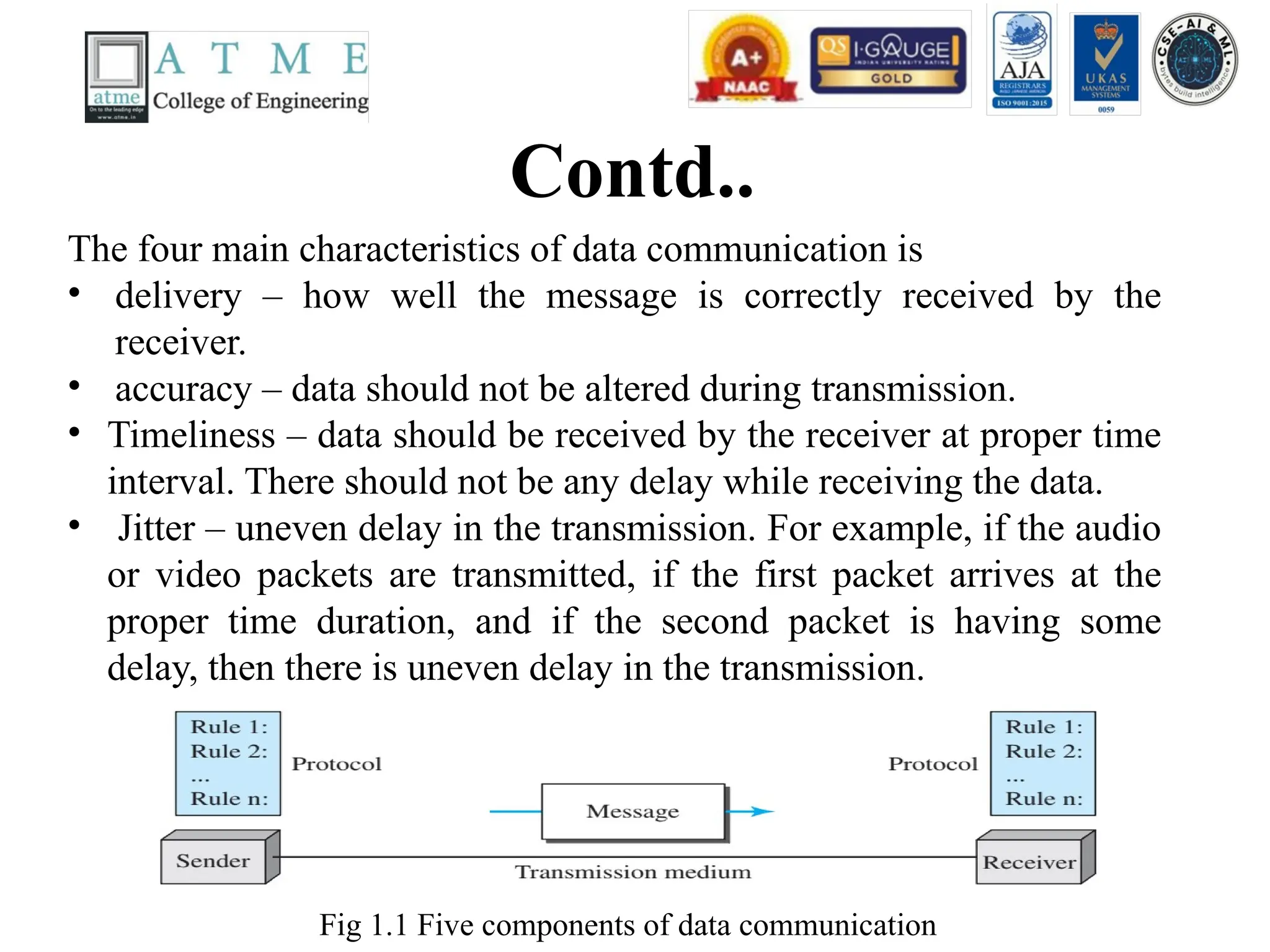
Fig 1.1 Fivecomponents of data communication
The four main characteristics of data communication is
• delivery – how well the message is correctly received by the
receiver.
• accuracy – data should not be altered during transmission.
• Timeliness – data should be received by the receiver at proper time
interval. There should not be any delay while receiving the data.
• Jitter – uneven delay in the transmission. For example, if the audio
or video packets are transmitted, if the first packet arrives at the
proper time duration, and if the second packet is having some
delay, then there is uneven delay in the transmission.
12.
Contd..
• The fivemain components of data communication
system are
• Message – text, numbers, audio, video, etc…
• Sender- transmits the message. Ex: computer, Phone,
video camera, etc…
• Receiver – receives the message. Ex: computer,
television, phone, etc…
• Transmission medium – twisted pair wire, coaxial
cable, fiber optic cable, etc….
• Protocol – set of rules during transmission. Ex: a
person speaking one language to another person who
may not be knowing that language.
13.
Data Representation
• Text:bit pattern Ex: Unicode, ASCII.
• Numbers: decimal numbers converted directly to
binary.
• Images : divided into a matrix of pixels Ex: binary
image (0’s and 1’s), RGB, and YCM image.
• Audio: representation of sound by an analog or a
digital signal.
• Video: represented by an analog or digital signal.
14.
Data Flow
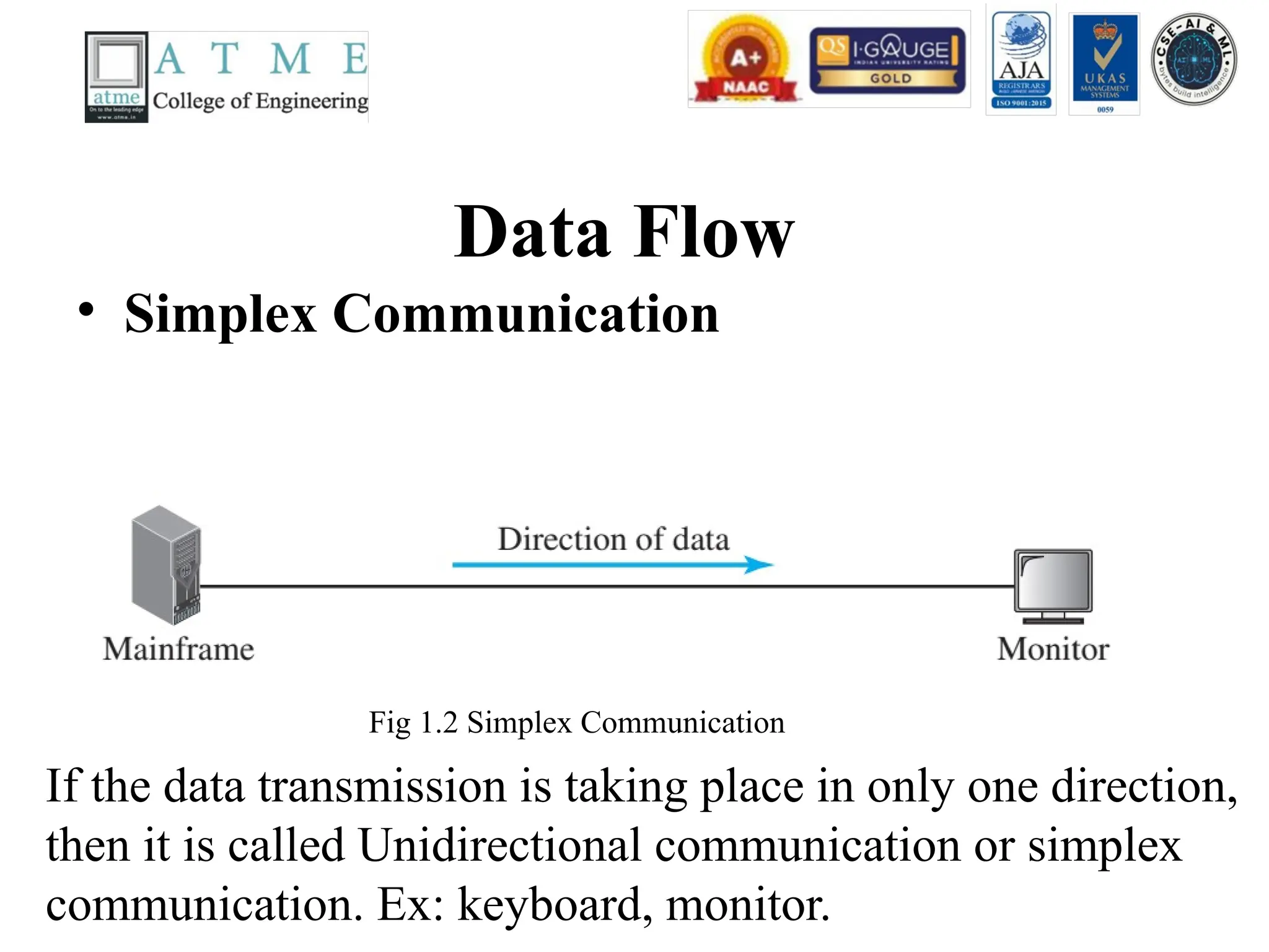
• SimplexCommunication
If the data transmission is taking place in only one direction,
then it is called Unidirectional communication or simplex
communication. Ex: keyboard, monitor.
Fig 1.2 Simplex Communication
15.
Contd..
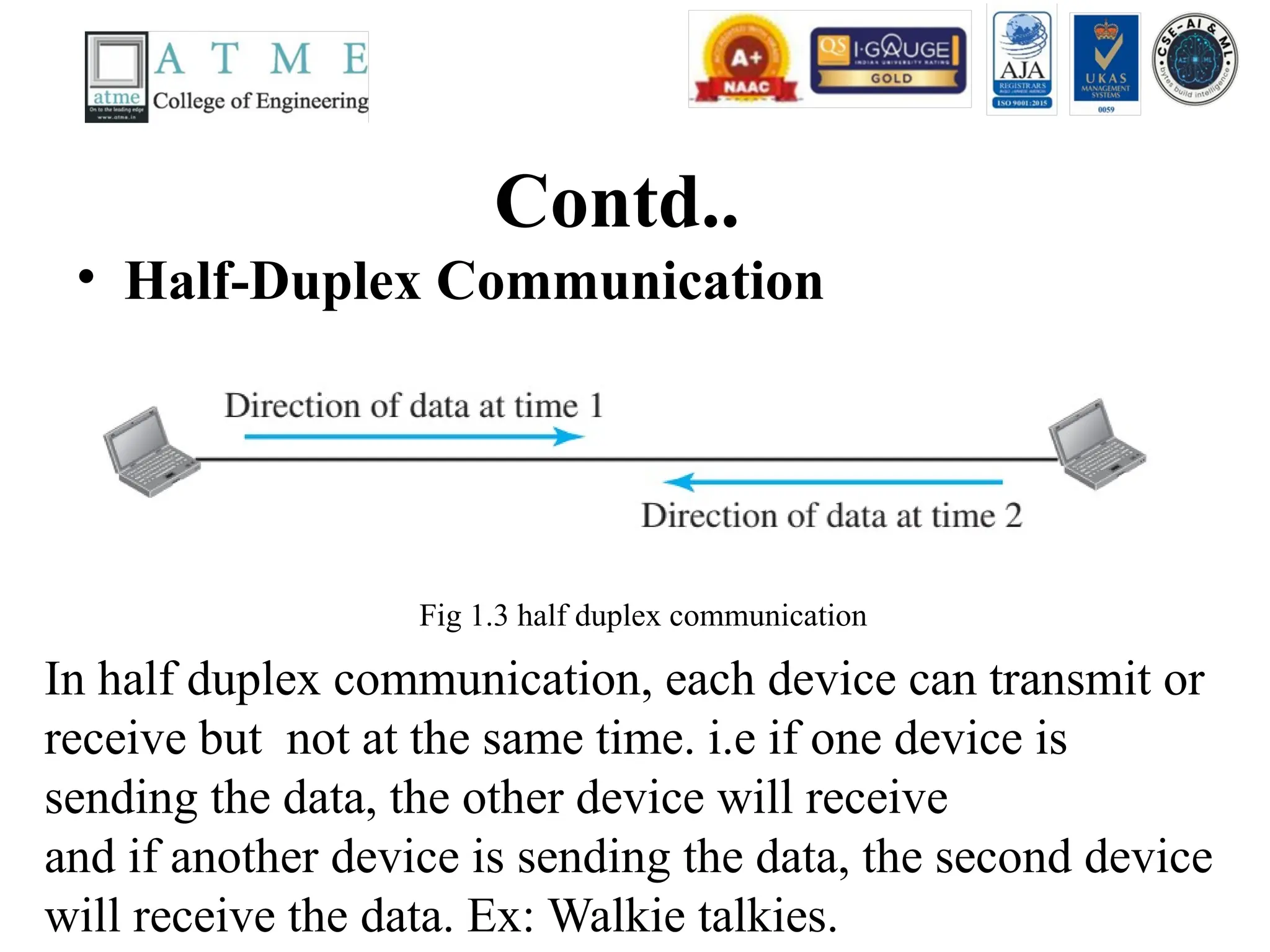
• Half-Duplex Communication
Inhalf duplex communication, each device can transmit or
receive but not at the same time. i.e if one device is
sending the data, the other device will receive
and if another device is sending the data, the second device
will receive the data. Ex: Walkie talkies.
Fig 1.3 half duplex communication
16.
Contd…
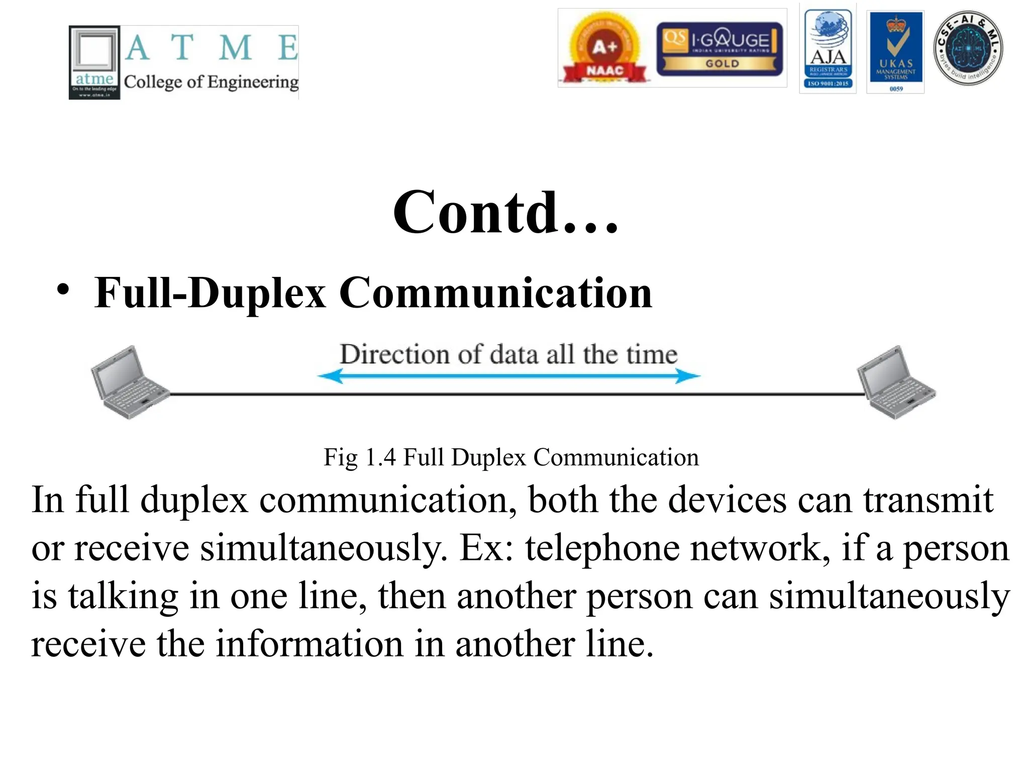
• Full-Duplex Communication
Infull duplex communication, both the devices can transmit
or receive simultaneously. Ex: telephone network, if a person
is talking in one line, then another person can simultaneously
receive the information in another line.
Fig 1.4 Full Duplex Communication
17.
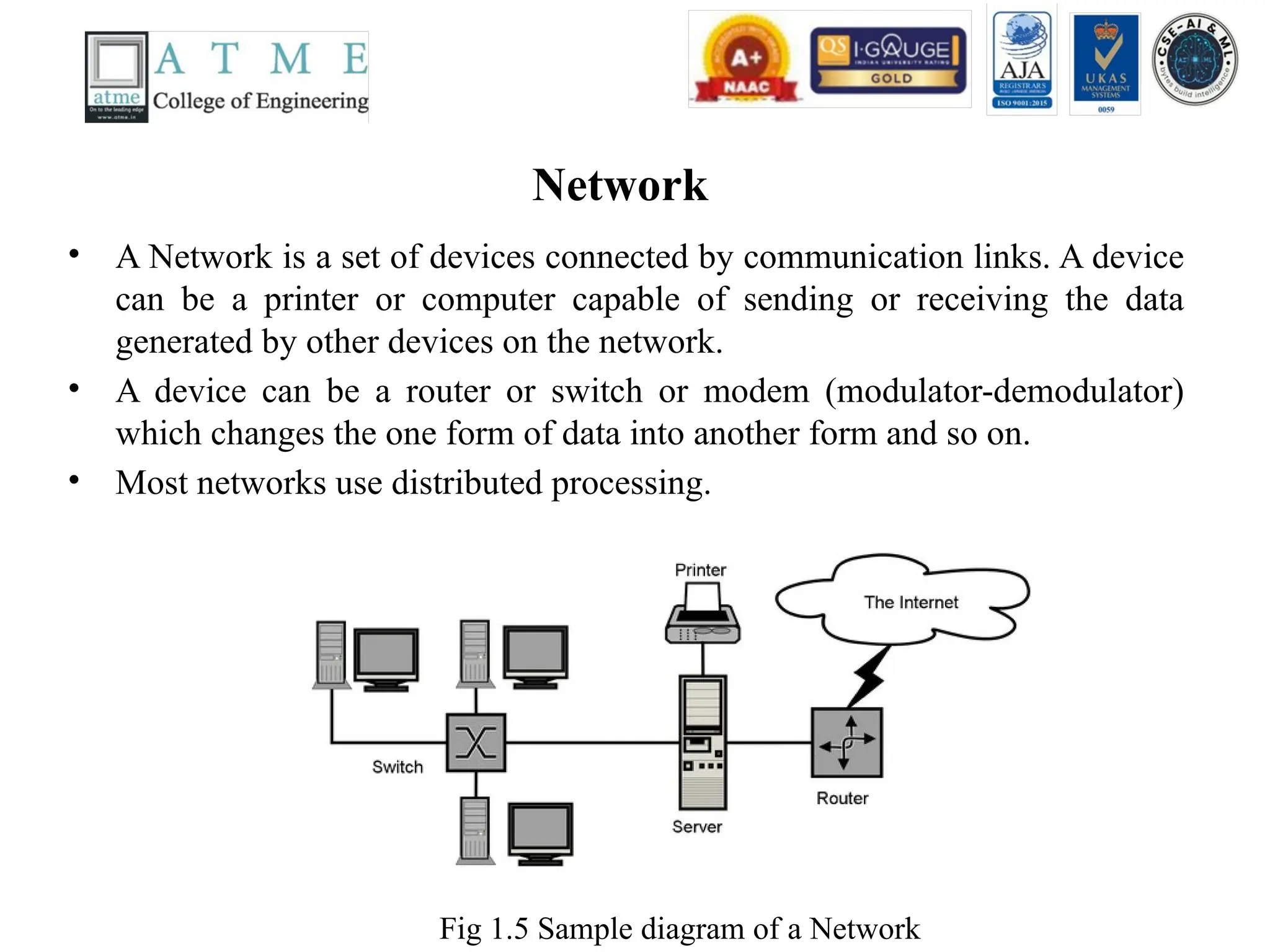
Network
• A Networkis a set of devices connected by communication links. A device
can be a printer or computer capable of sending or receiving the data
generated by other devices on the network.
• A device can be a router or switch or modem (modulator-demodulator)
which changes the one form of data into another form and so on.
• Most networks use distributed processing.
Fig 1.5 Sample diagram of a Network
18.
Network Criteria
• Themost important parameters for network criteria
are
• Performance – transit time and response time,
throughput and delay. Transit time is the time
required for the message or information to travel
from one device to another device. Response time is
the time elapsed between the inquiry and response.
• If we try to send more data to the network, it will
result in increase in throughput and delay. Delay
arises because of traffic congestion in the network.
19.
Contd..
• Reliability –the time needed to recover from
the failure of the device during
transmitting/receiving the data.
• Security – Protection of data from
unauthorized users. Ex : Protection of data
from Gmail account, and email-access.
20.
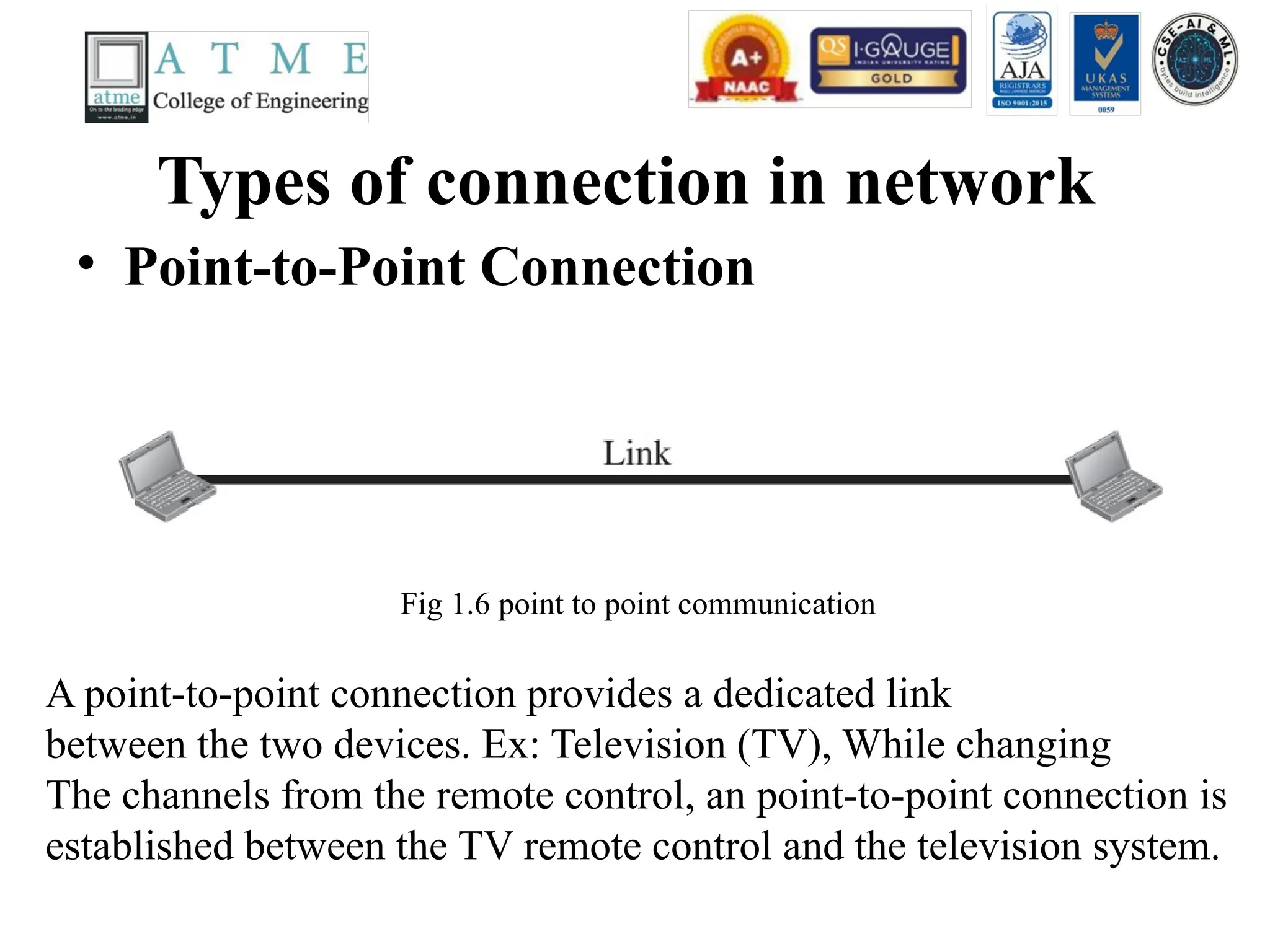
Types of connectionin network
• Point-to-Point Connection
Fig 1.6 point to point communication
A point-to-point connection provides a dedicated link
between the two devices. Ex: Television (TV), While changing
The channels from the remote control, an point-to-point connection is
established between the TV remote control and the television system.
21.
Contd…
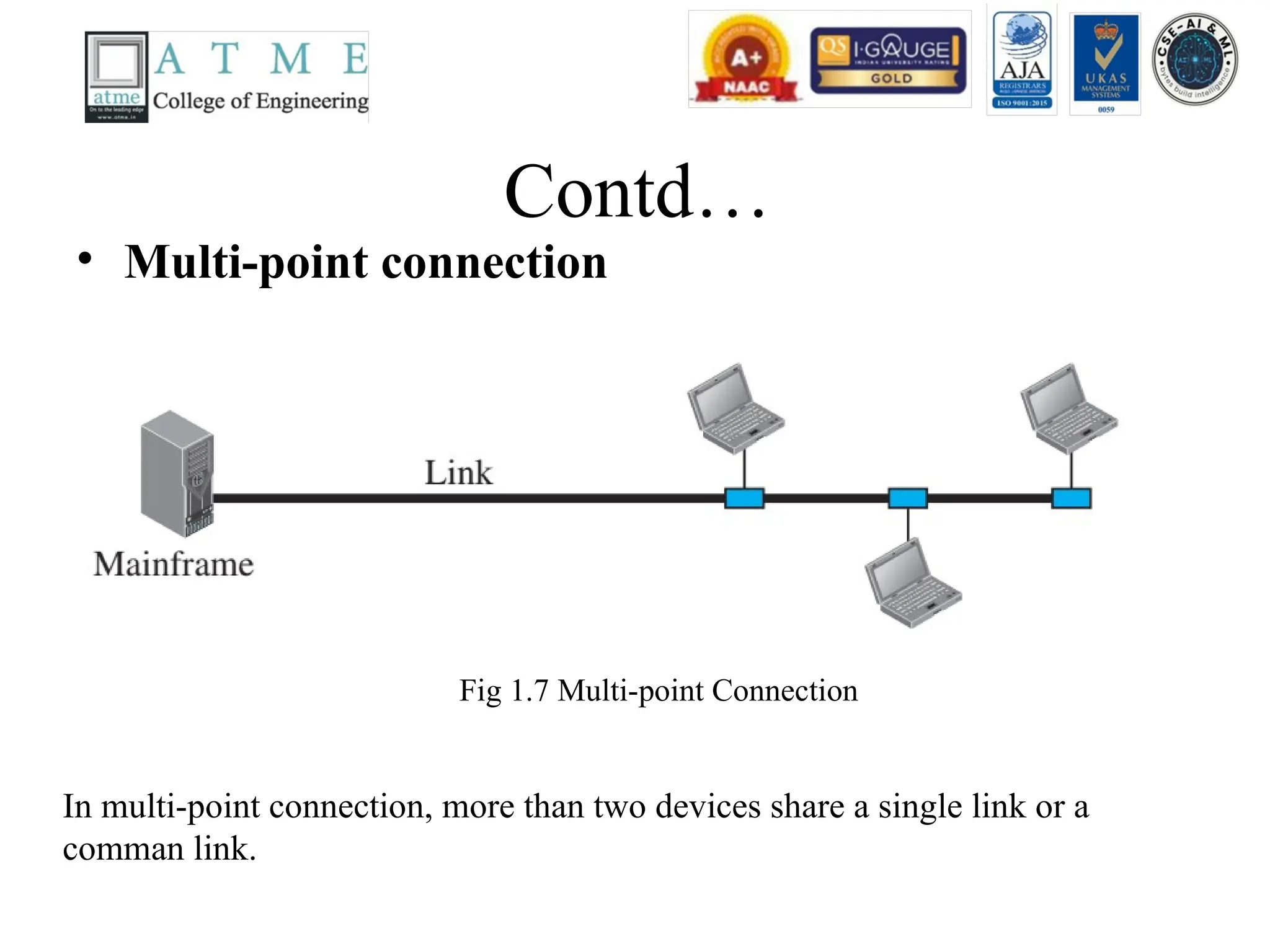
• Multi-point connection
Inmulti-point connection, more than two devices share a single link or a
comman link.
Fig 1.7 Multi-point Connection
Contd..
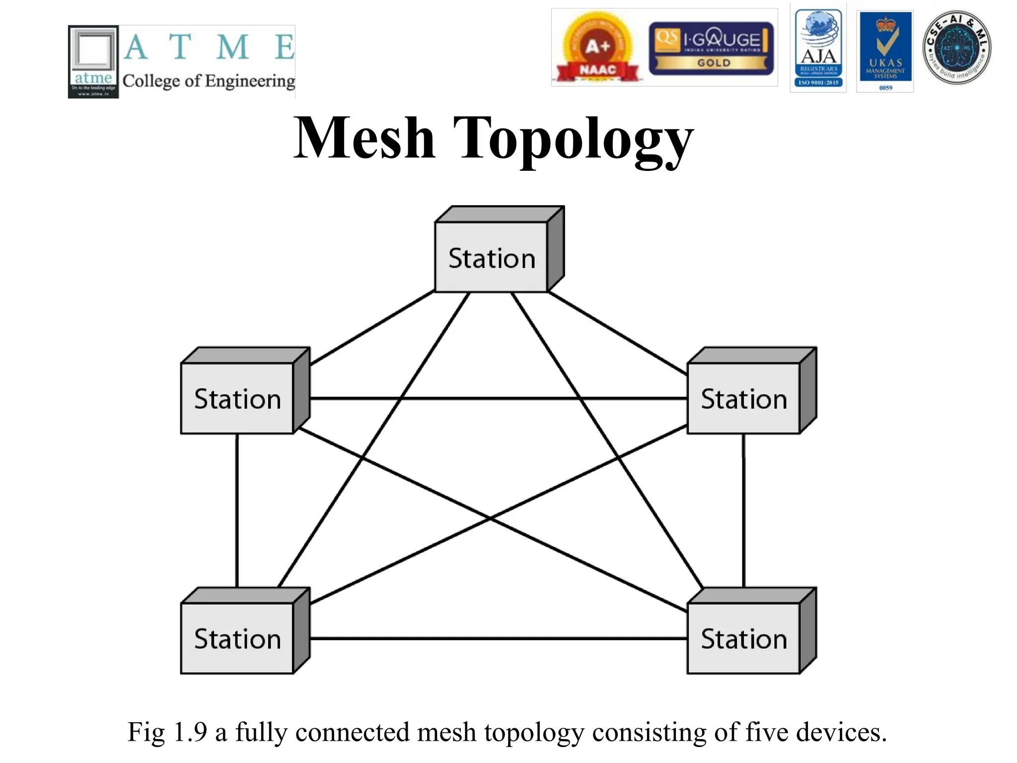
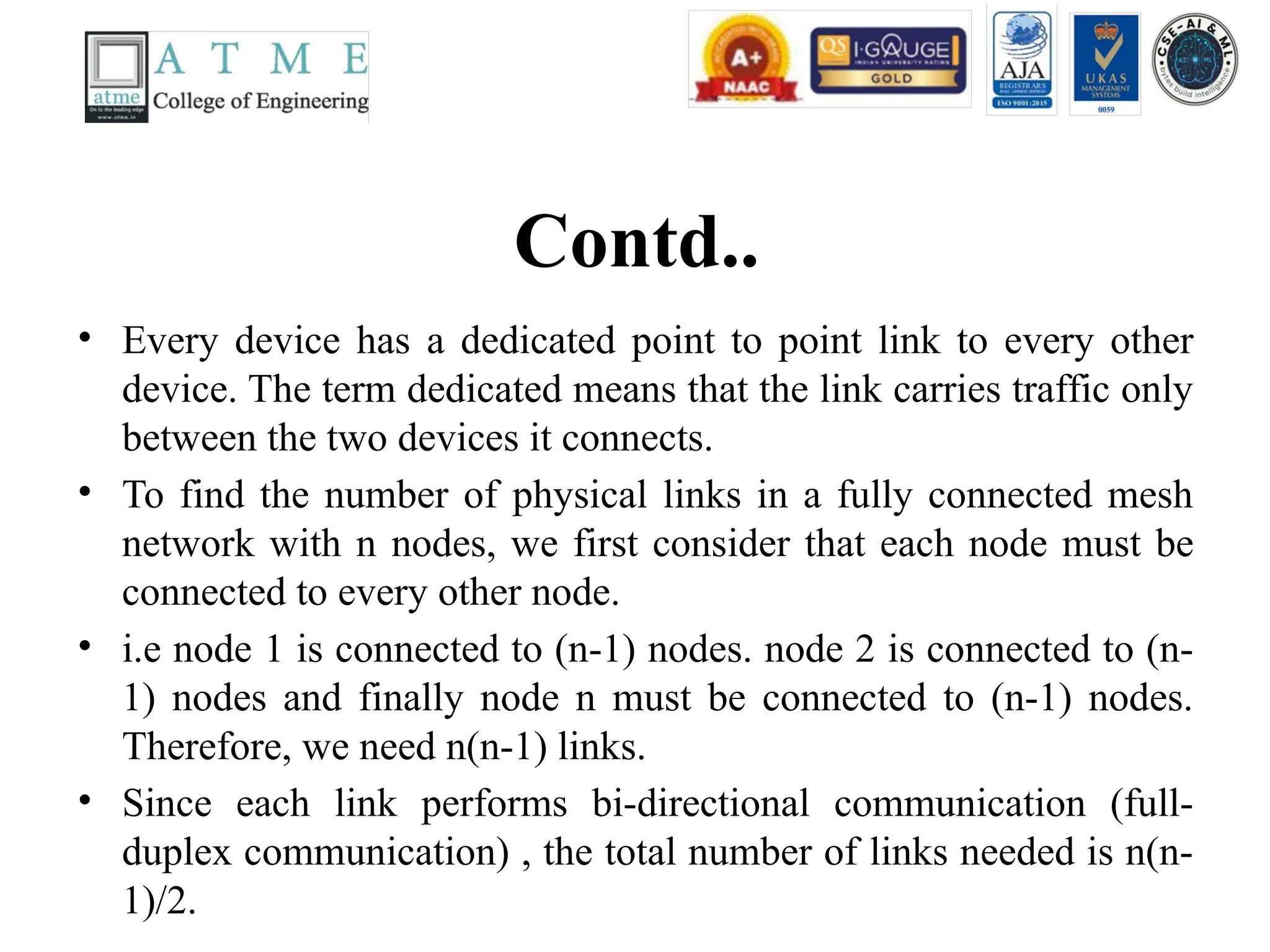
• Every devicehas a dedicated point to point link to every other
device. The term dedicated means that the link carries traffic only
between the two devices it connects.
• To find the number of physical links in a fully connected mesh
network with n nodes, we first consider that each node must be
connected to every other node.
• i.e node 1 is connected to (n-1) nodes. node 2 is connected to (n-
1) nodes and finally node n must be connected to (n-1) nodes.
Therefore, we need n(n-1) links.
• Since each link performs bi-directional communication (full-
duplex communication) , the total number of links needed is n(n-
1)/2.
Contd..
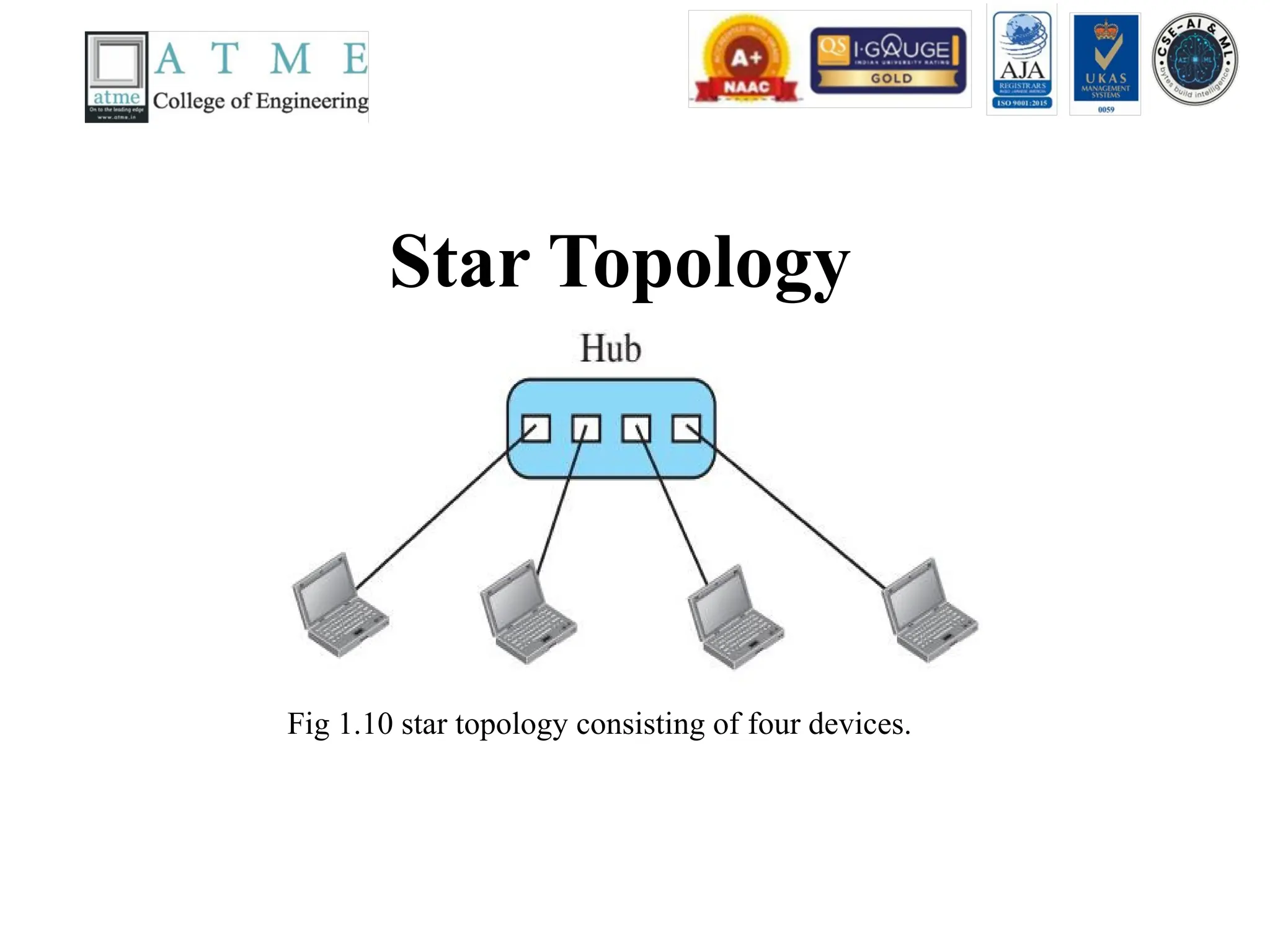
• In astar topology, each device has a dedicated point-
to-point link only to a central controller, usually
called a hub.
• The devices are not directly linked to one another.
Unlike a mesh topology, a star topology does not
allow direct traffic between devices.
• The controller acts as an exchange: If one device
wants to send data to another, it sends the data to the
controller, which then relays the data to the other
connected device.
27.
Categories of Networks
•Local Area Network (LAN) – LAN is a
privately owned network which connects the
devices in a single office, building, or campus.
LAN size is limited to the area less than 2
miles or few kilometres. Ex: sharing two
computers and a printer in one office.
Establishing a lab which consists of 20 pc’s
and one server in a single room or office.
28.
Bus Topology
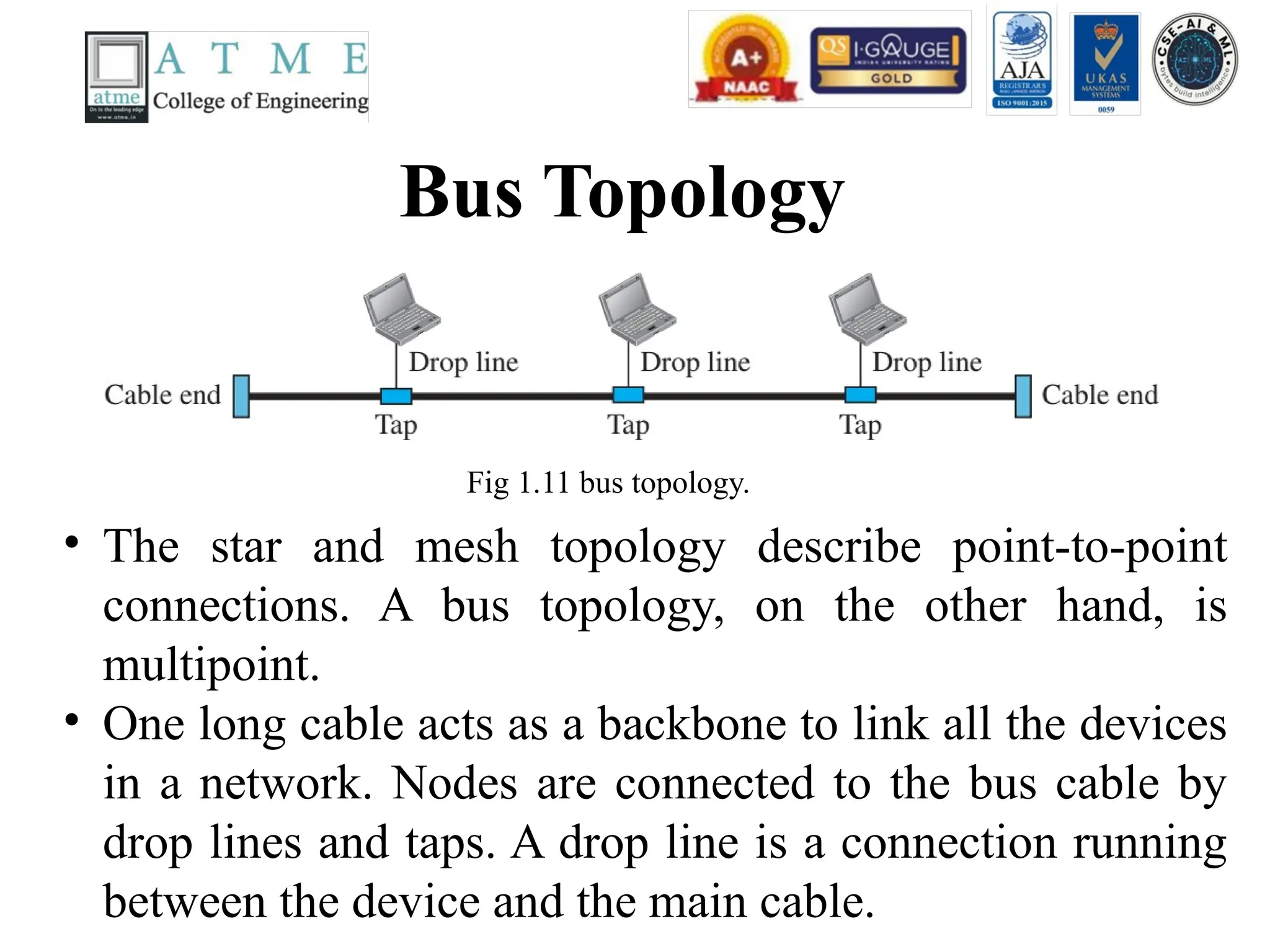
Fig 1.11bus topology.
• The star and mesh topology describe point-to-point
connections. A bus topology, on the other hand, is
multipoint.
• One long cable acts as a backbone to link all the devices
in a network. Nodes are connected to the bus cable by
drop lines and taps. A drop line is a connection running
between the device and the main cable.
29.
Contd..
• A tapis a connector that either splices into the
main cable or punctures the sheathing of a cable
to create a contact with the metallic core. As a
signal travels along the backbone, some of its
energy is transformed into heat.
• Therefore, it becomes weaker and weaker as it
travels farther and farther. For this reason there
is a limit on the number of taps a bus can
support and on the distance between those taps.
30.
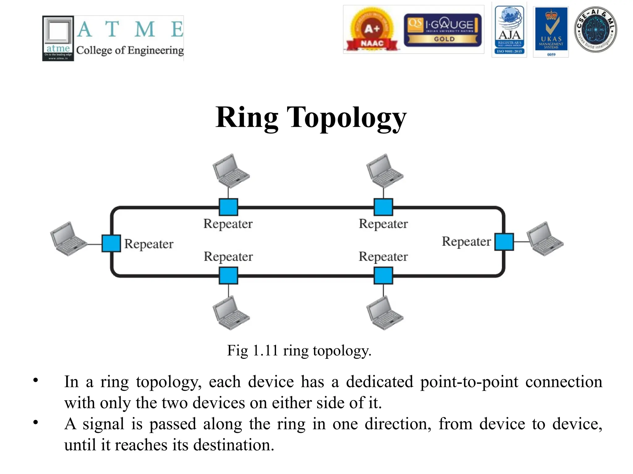
Ring Topology
Fig 1.11ring topology.
• In a ring topology, each device has a dedicated point-to-point connection
with only the two devices on either side of it.
• A signal is passed along the ring in one direction, from device to device,
until it reaches its destination.
31.
Contd..
• Each devicein the ring incorporates a repeater.
When a device receives a signal intended for
another device, its repeater regenerates the bits
and passes them along.
Wide Area Network(WAN)
• A wide area network provides long-distance
transmission of data, image, audio, and video
information over large geographic areas that
may include a country, continent, or even the
whole world.
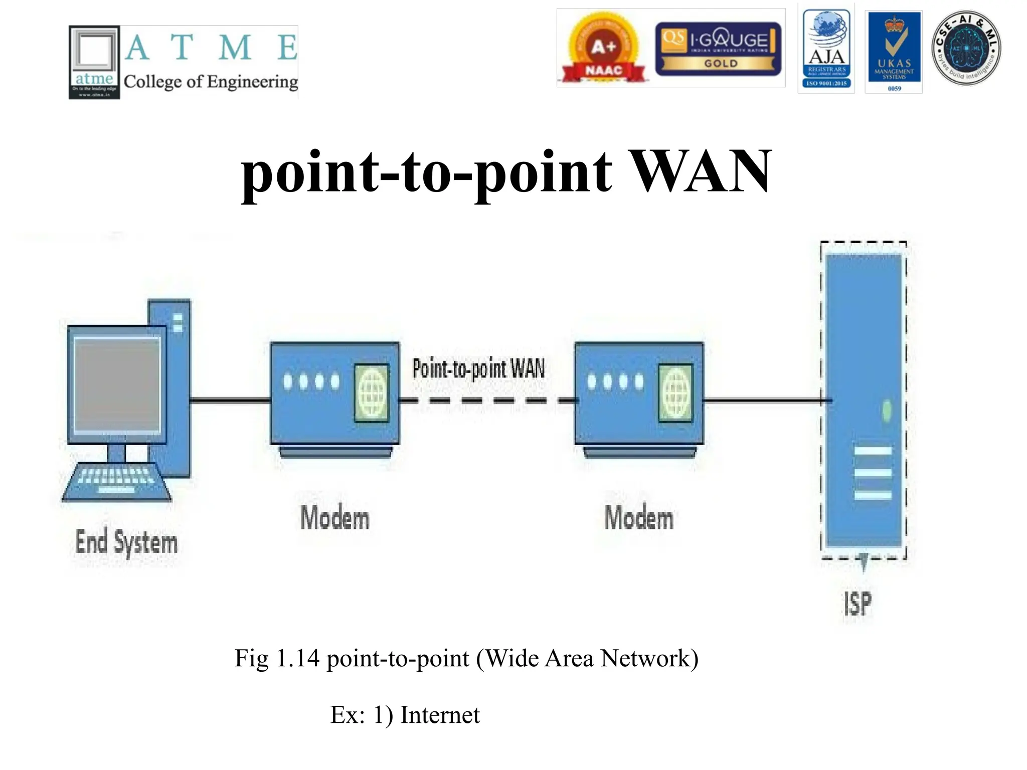
• There are two kinds of WAN
(a) Switched WAN
(b) point-to-point WAN
34.
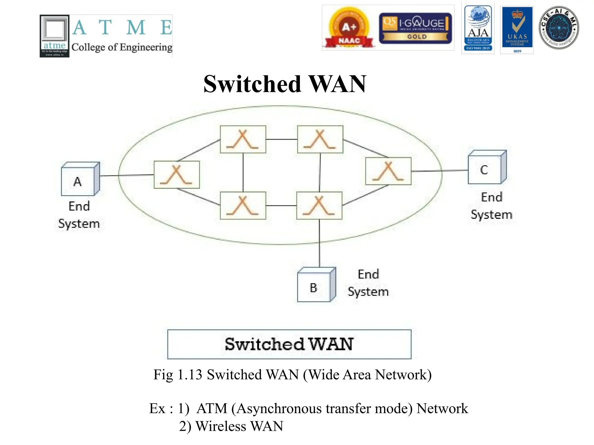
Switched WAN
Fig 1.13Switched WAN (Wide Area Network)
Ex : 1) ATM (Asynchronous transfer mode) Network
2) Wireless WAN
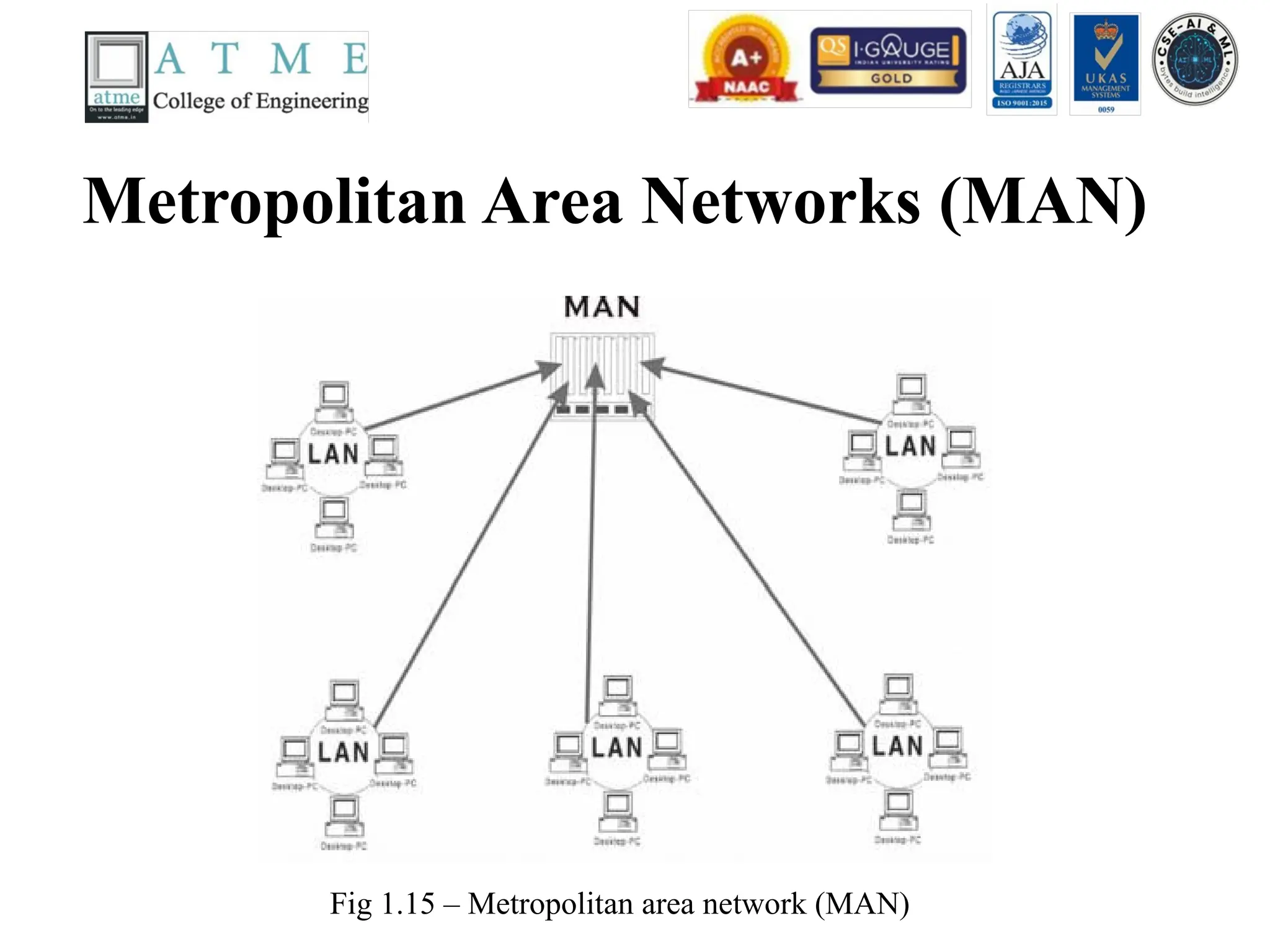
Contd..
• A Metropolitanarea network (MAN) is a
network with a size between a LAN and a
WAN. It normally covers the area inside a
town or a city. It is designed for customers
who need high-speed connectivity, normally to
the internet, and have endpoints spread over
the city or part of city.
• Ex: Telephone Network, Cable TV Network
38.
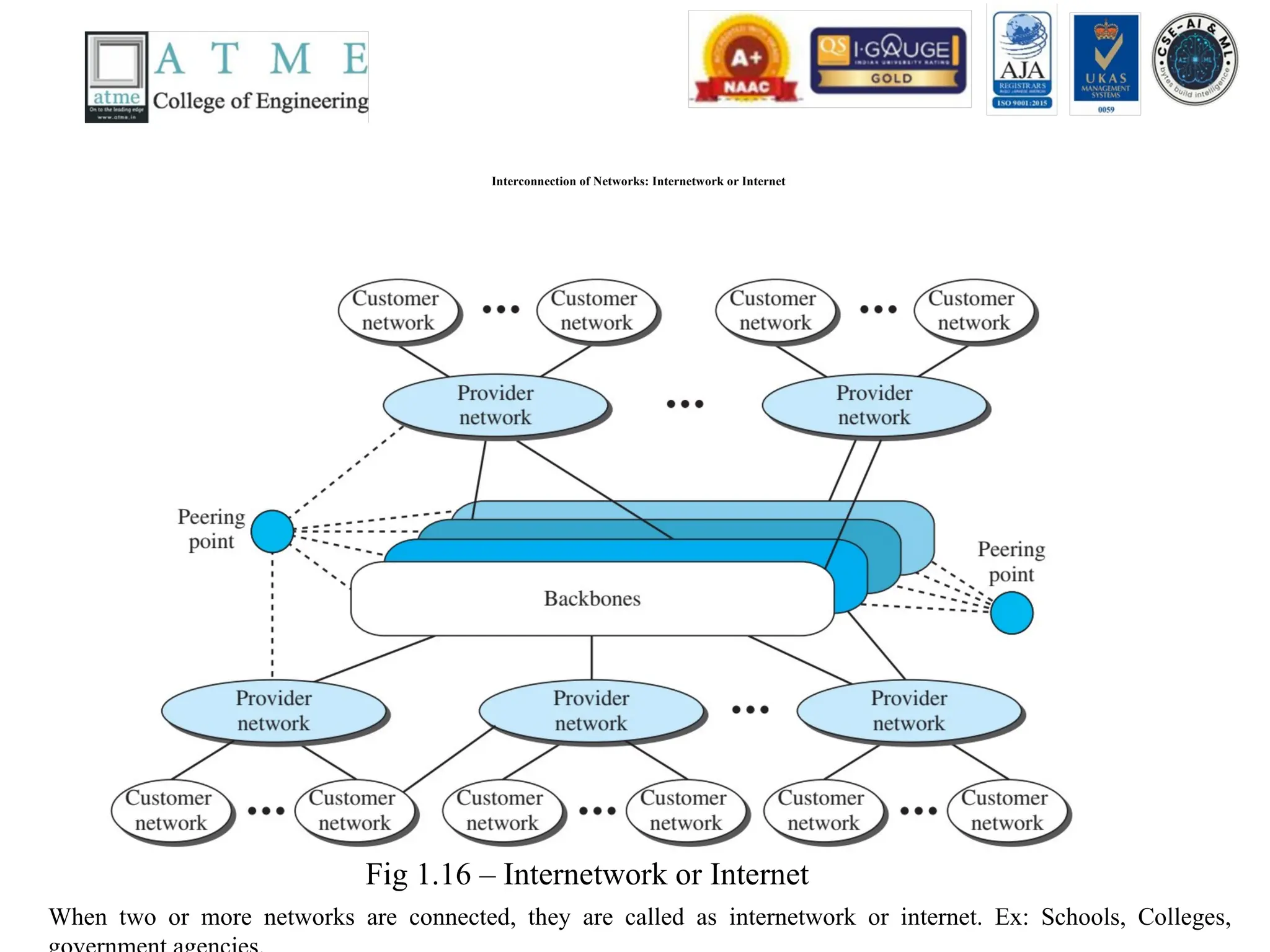
Interconnection of Networks:Internetwork or Internet
When two or more networks are connected, they are called as internetwork or internet. Ex: Schools, Colleges,
Fig 1.16 – Internetwork or Internet
39.
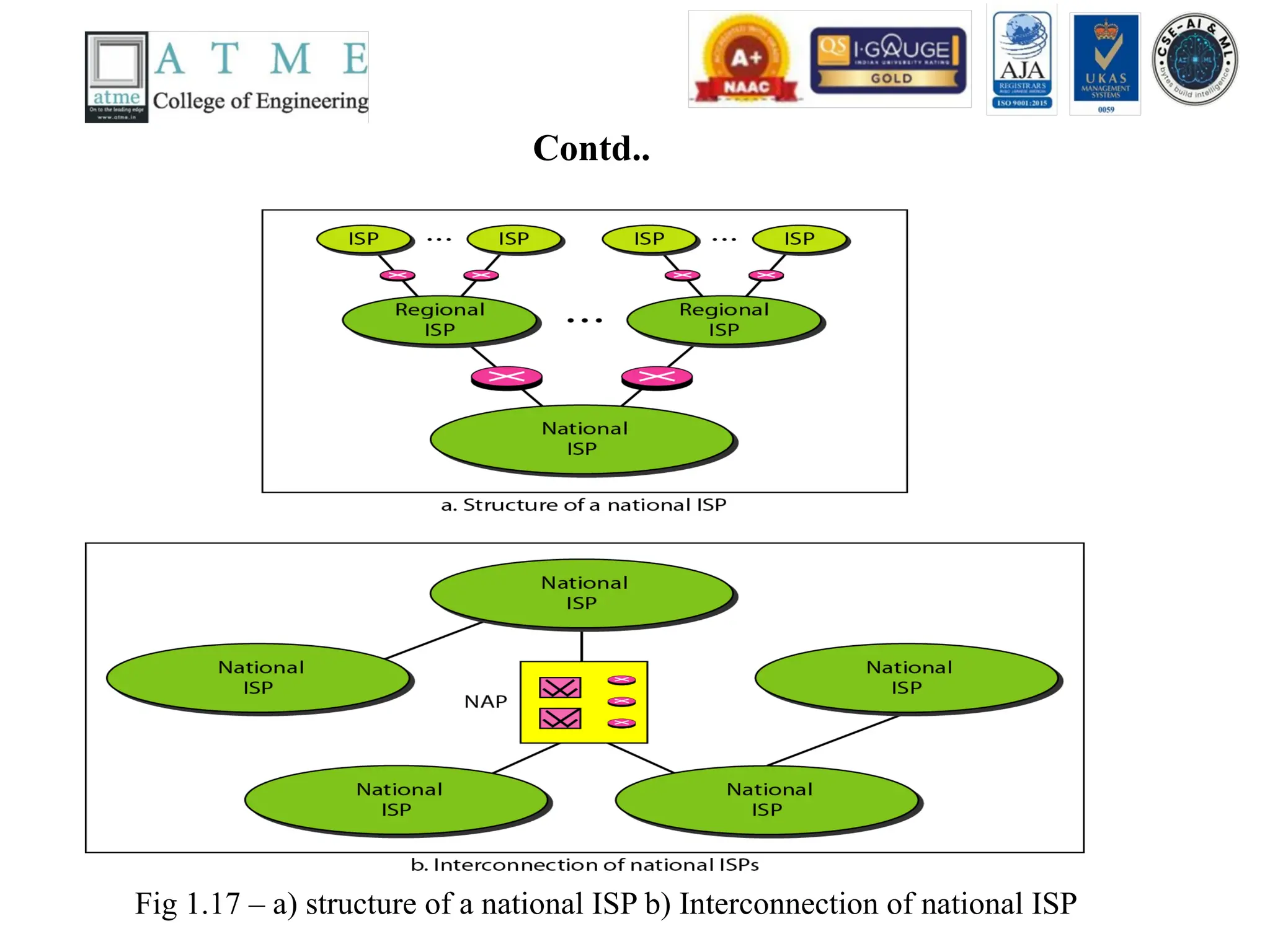
Contd..
Fig 1.17 –a) structure of a national ISP b) Interconnection of national ISP
40.
Contd..
• To provideinternet to the users, Internet service
Providers (ISP) are used. There are different kinds of
Internet Service Providers namely
• International Internet Service Provider
• National Internet Service Provider Ex: Jio, BSNL,
Airtel, etc..- higher data rate
• Regional Internet Service Provider Ex: Bharat Broad
Band Network Limited (BBNL) in Banglore –smaller
data rate.
• Local Internet Service Provider Ex: College or
41.
The Protocol
• Aprotocol is a set of rules that governs data communications
• It defines what is communicated, how it is communicated and when it is
communicated.
• The key elements of the protocol are
• Syntax - Structure or format of data, meaning the order in which they are
presented for example, if I have a 24-bits of data, the first 8-bits can be
considered as an address of the sender, the last 8-bits can be considered as an
address of the receiver and the middle 8-bits can be considered as an
message or information.
• Semantics - Refer to the meaning of each section of bits, how a pattern is
interpreted and what action to be taken.
• Timing - Refers to when data should be sent and how fast can they be sent.
For example, if a sender produces data at 100Mpbs, and the receiver has the
capacity to process the data at 1Mbps. The transmission will overload and
some data will be lost.
42.
Standards
• Standards areessential in creating and maintaining an open and
competitive market for equipment manufacturers.
• Required to guarantee national and international interoperability of
data and telecommunications technology and processes.
• Standards provides guidelines to manufacturers, vendors,
government agencies, and other service providers to ensure the kind
of interconnectivity necessary in today’s marketplace.
• Categories of data communications standards
• Defacto (“by fact” or “by convention”) :
• Standards that have not been approved by an organizational body
but have been adopted through wide spread use, eg. model TCP/IP)
• Dejure (“by law” or “by regulation”):
• Those that have been legislated by an official recognized body, eg.
OSI model
43.
Standards Organizations
• Someof the important standards organization are
• International Organization for Standardization (ISO) – ISO is a
multinational body which has drawn membership from standard
creation committees of various governments.
• International Tele Communication Union – Telecommunication
Standards Sector (ITU-T) – the consultative committee for
international telephony and telegraphy (CCITT) – standards for
telecommunication in phone particular.
• American National Standards Institute (ANSI) – it is private
standards institute not affiliated to U.S federal government.
• Institute of Electrical and Electronics Engineers (IEEE) – largest
professional engineering society
• Electronic Industries Association (EIA) - used for promotion of
electronic manufacturing concerns.
44.
Network Models
• Heremainly we are going to discuss different
kinds of network models a) Open System
Interconnect (OSI) Model
• b) Transmission Control Protocol (TCP) /
Internet Protocol (IP) Model
45.
Layered Tasks
• Weuse the concept of layers in our daily life.
As an example, let us consider two friends
who communicate through postal mail. The
process of sending a letter to a friend would be
complex if there were no services available
from the post office. Fig 1.18 shows the steps
in this task.
46.
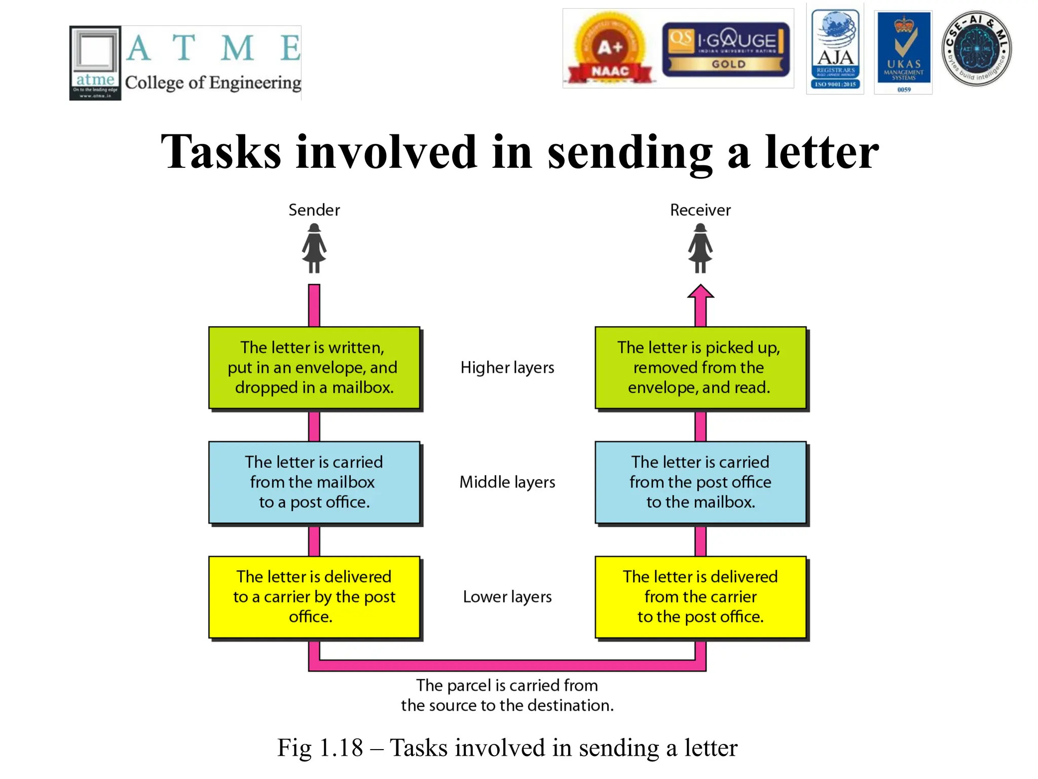
Tasks involved insending a letter
Fig 1.18 – Tasks involved in sending a letter
47.
Contd..
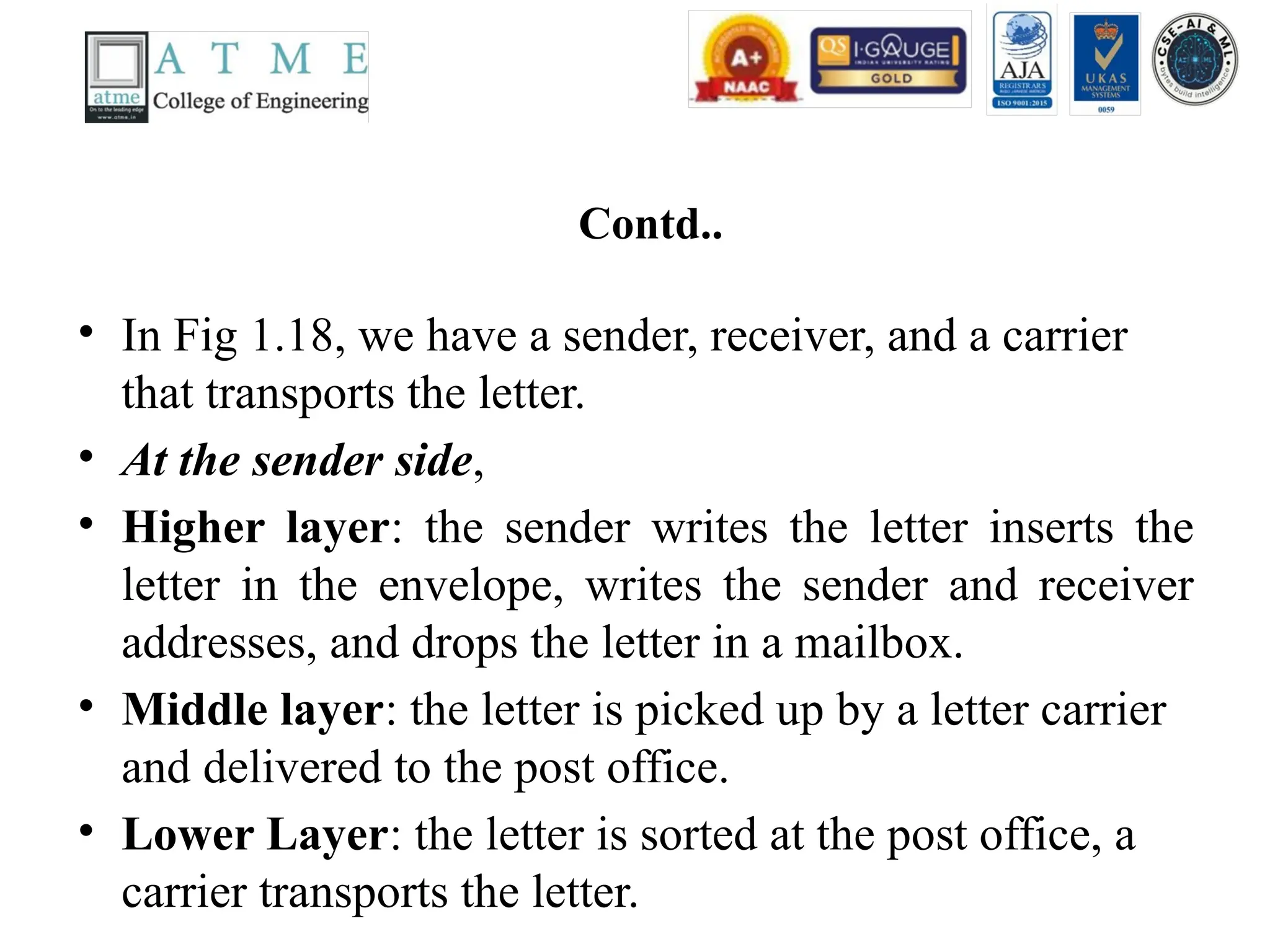
• In Fig1.18, we have a sender, receiver, and a carrier
that transports the letter.
• At the sender side,
• Higher layer: the sender writes the letter inserts the
letter in the envelope, writes the sender and receiver
addresses, and drops the letter in a mailbox.
• Middle layer: the letter is picked up by a letter carrier
and delivered to the post office.
• Lower Layer: the letter is sorted at the post office, a
carrier transports the letter.
48.
Contd..
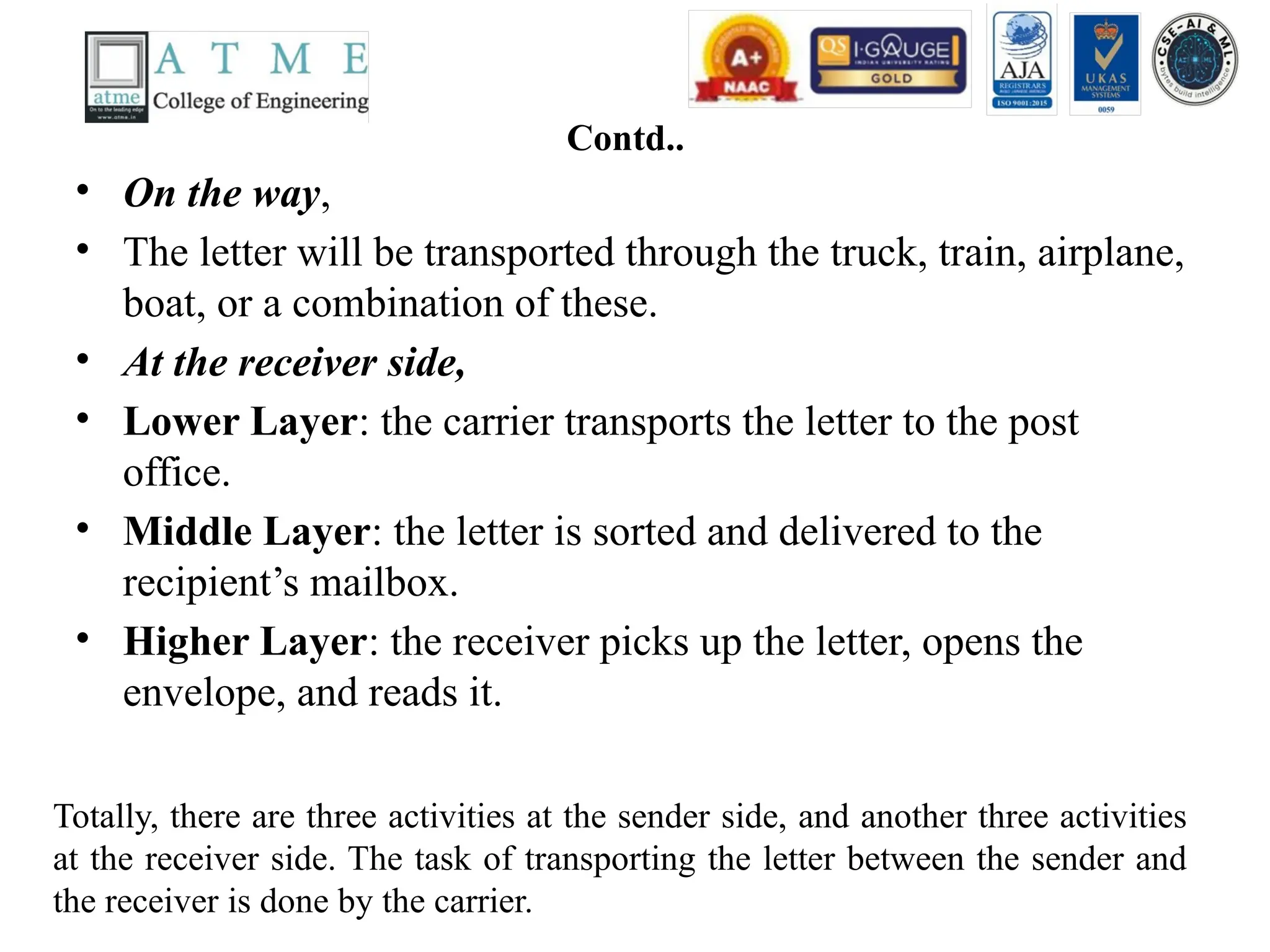
• On theway,
• The letter will be transported through the truck, train, airplane,
boat, or a combination of these.
• At the receiver side,
• Lower Layer: the carrier transports the letter to the post
office.
• Middle Layer: the letter is sorted and delivered to the
recipient’s mailbox.
• Higher Layer: the receiver picks up the letter, opens the
envelope, and reads it.
Totally, there are three activities at the sender side, and another three activities
at the receiver side. The task of transporting the letter between the sender and
the receiver is done by the carrier.
49.
The OSI Model
•Established in 1947, the International
Standards Organization(ISO) is a multinational
body dedicated to world wide agreement on
international standards. An ISO standard that
covers all aspects of network communications
is the Open Systems Interconnection(OSI)
model. It was first introduced in the late 1970s.
50.
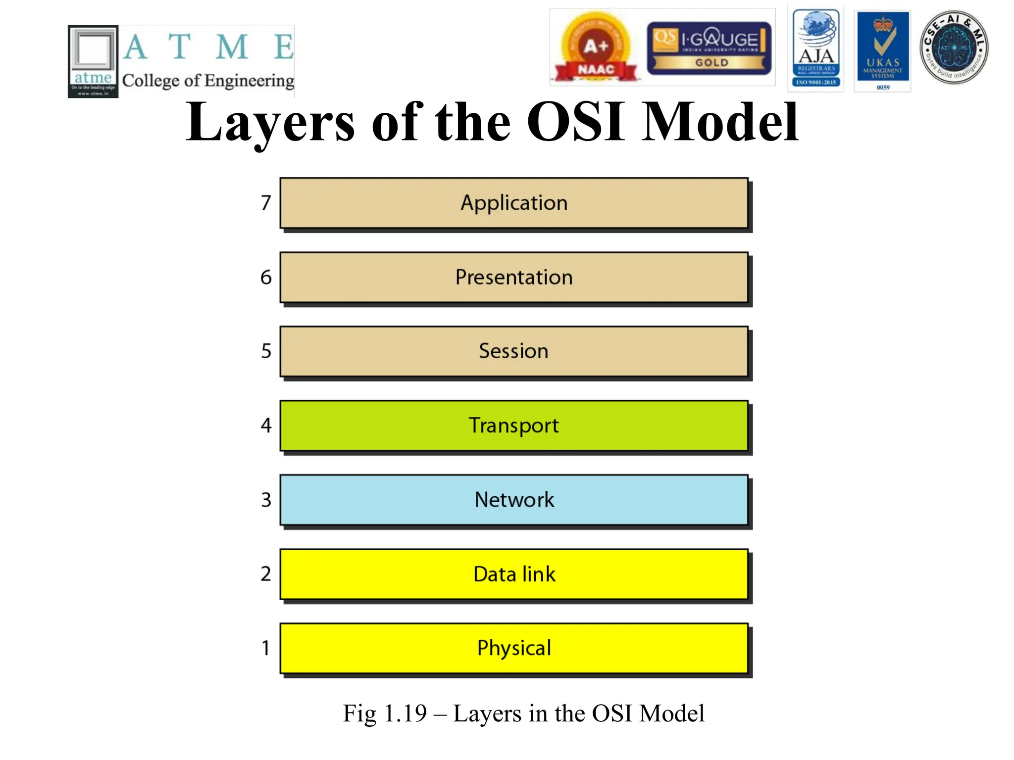
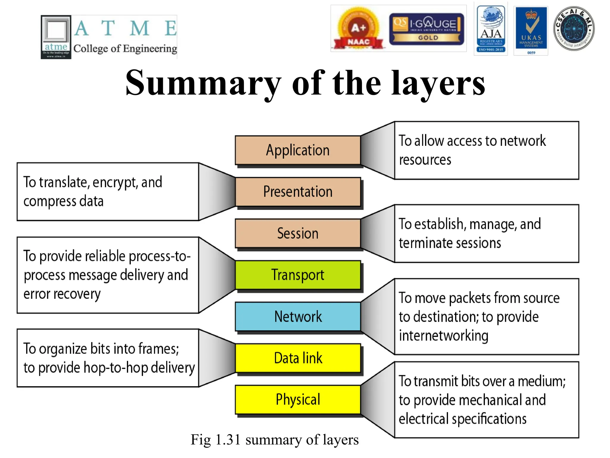
Layers of theOSI Model
Fig 1.19 – Layers in the OSI Model
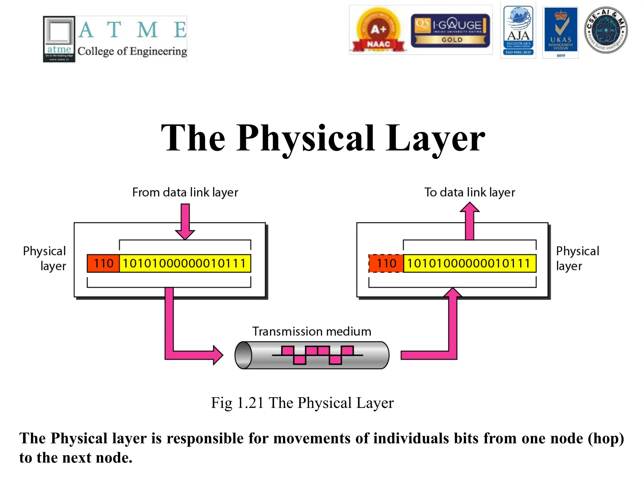
The Physical Layer
Fig1.21 The Physical Layer
The Physical layer is responsible for movements of individuals bits from one node (hop)
to the next node.
53.
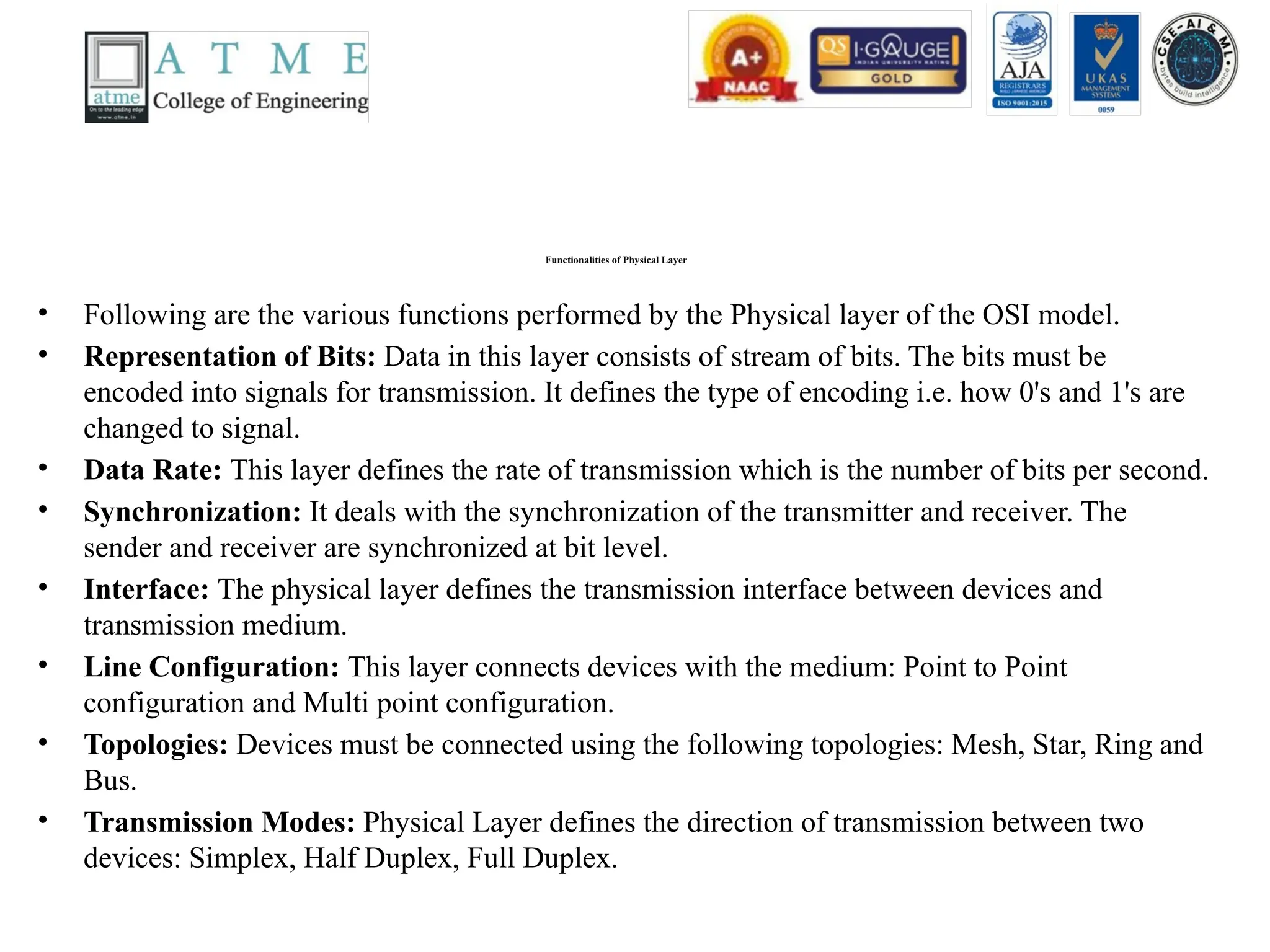
Functionalities of PhysicalLayer
• Following are the various functions performed by the Physical layer of the OSI model.
• Representation of Bits: Data in this layer consists of stream of bits. The bits must be
encoded into signals for transmission. It defines the type of encoding i.e. how 0's and 1's are
changed to signal.
• Data Rate: This layer defines the rate of transmission which is the number of bits per second.
• Synchronization: It deals with the synchronization of the transmitter and receiver. The
sender and receiver are synchronized at bit level.
• Interface: The physical layer defines the transmission interface between devices and
transmission medium.
• Line Configuration: This layer connects devices with the medium: Point to Point
configuration and Multi point configuration.
• Topologies: Devices must be connected using the following topologies: Mesh, Star, Ring and
Bus.
• Transmission Modes: Physical Layer defines the direction of transmission between two
devices: Simplex, Half Duplex, Full Duplex.
54.
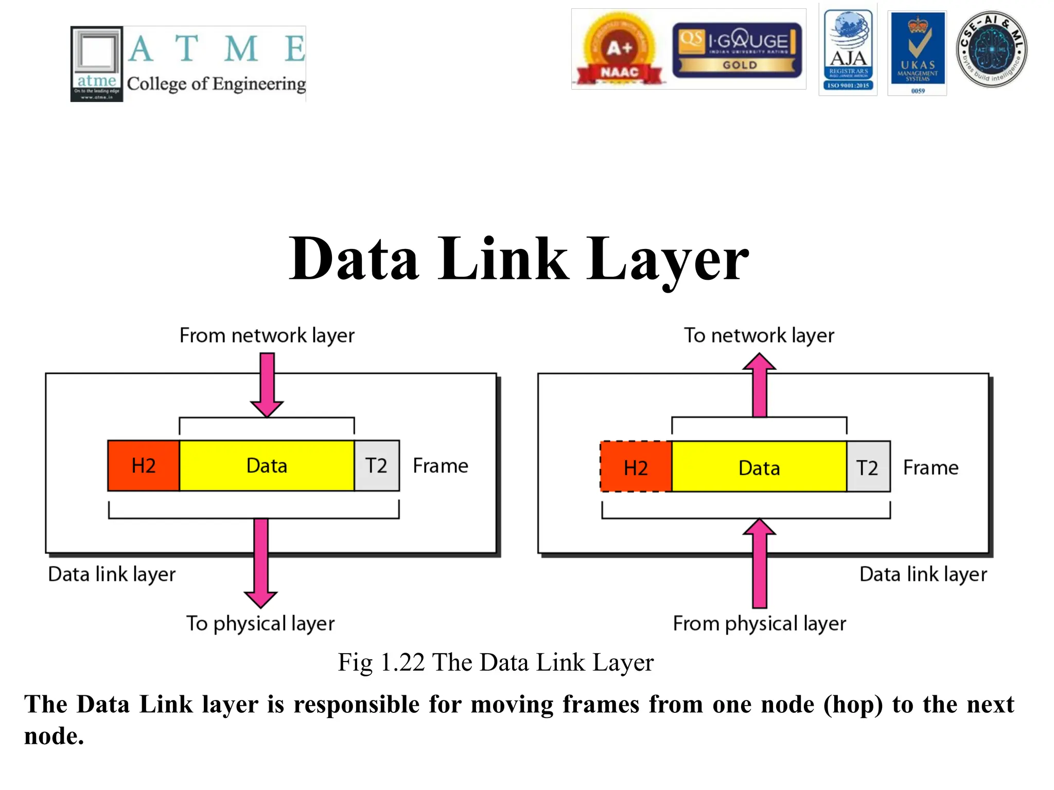
Data Link Layer
Fig1.22 The Data Link Layer
The Data Link layer is responsible for moving frames from one node (hop) to the next
node.
55.
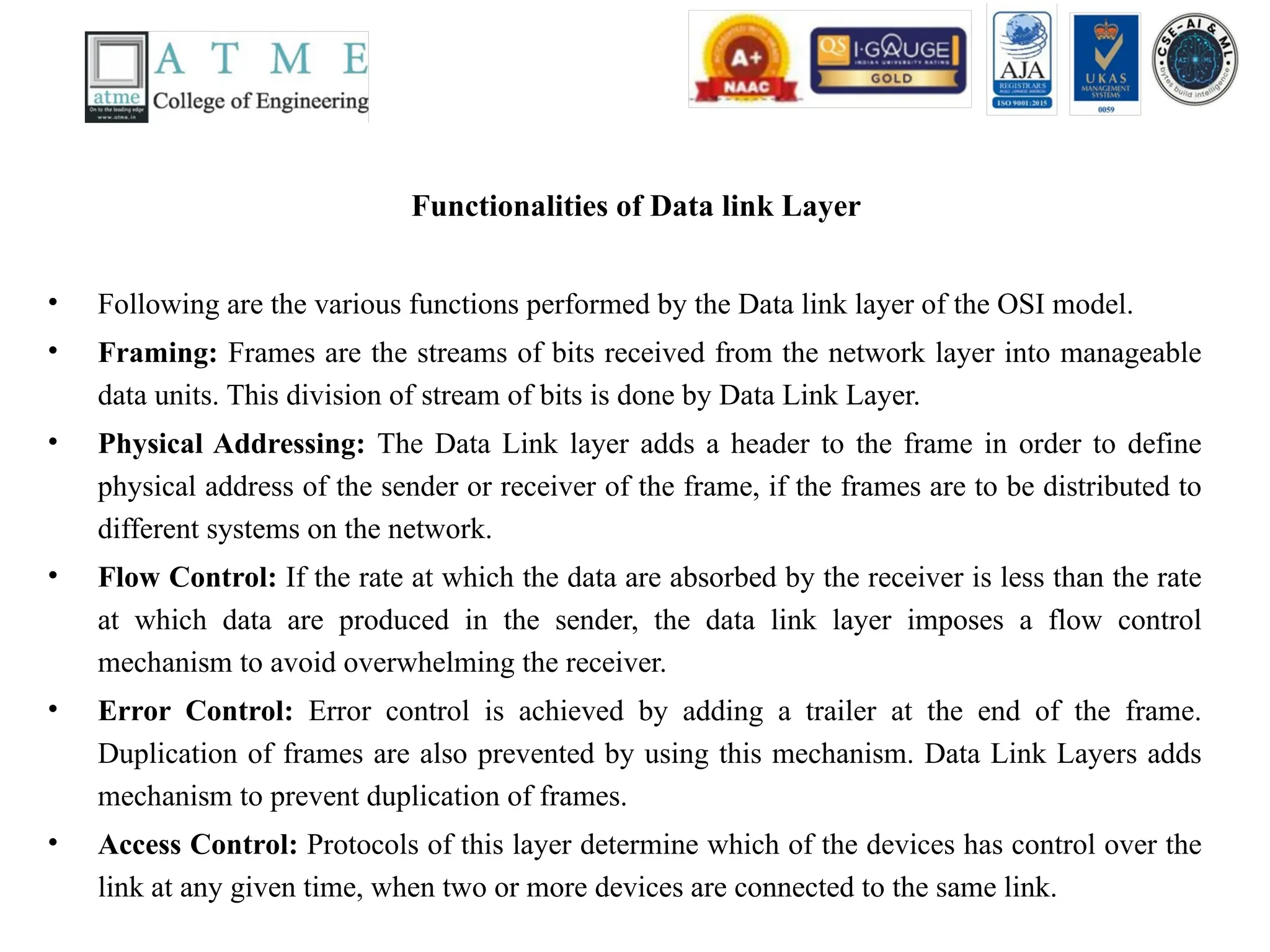
Functionalities of Datalink Layer
• Following are the various functions performed by the Data link layer of the OSI model.
• Framing: Frames are the streams of bits received from the network layer into manageable
data units. This division of stream of bits is done by Data Link Layer.
• Physical Addressing: The Data Link layer adds a header to the frame in order to define
physical address of the sender or receiver of the frame, if the frames are to be distributed to
different systems on the network.
• Flow Control: If the rate at which the data are absorbed by the receiver is less than the rate
at which data are produced in the sender, the data link layer imposes a flow control
mechanism to avoid overwhelming the receiver.
• Error Control: Error control is achieved by adding a trailer at the end of the frame.
Duplication of frames are also prevented by using this mechanism. Data Link Layers adds
mechanism to prevent duplication of frames.
• Access Control: Protocols of this layer determine which of the devices has control over the
link at any given time, when two or more devices are connected to the same link.
56.
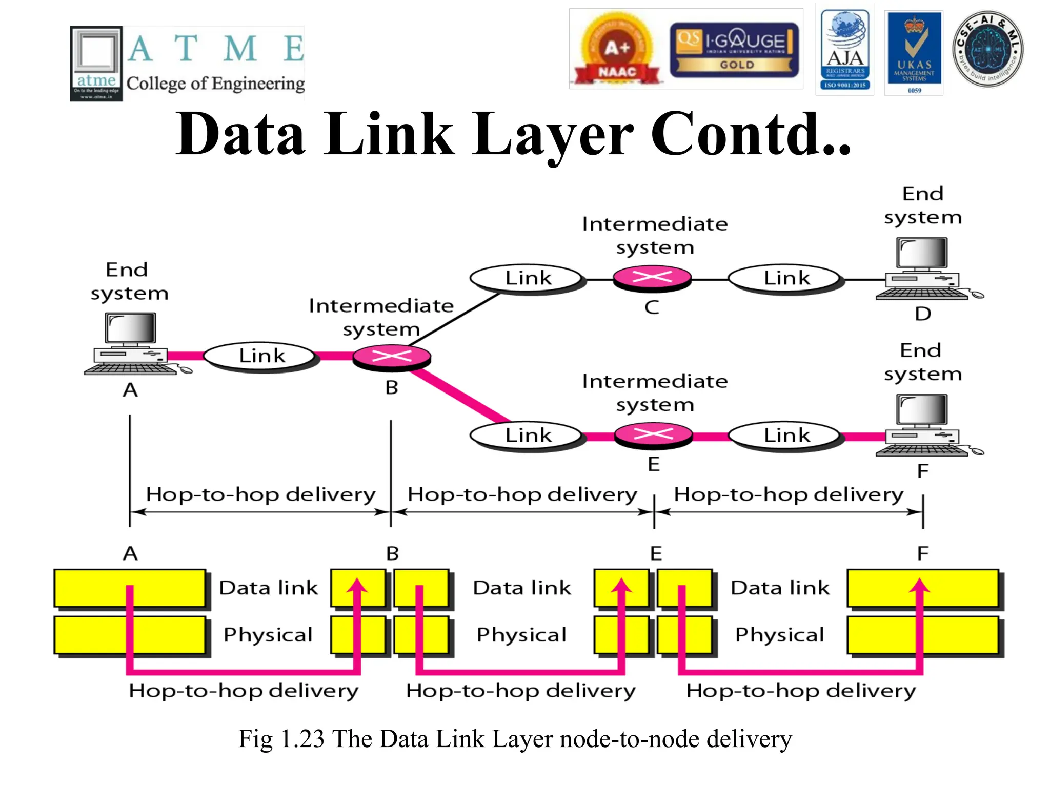
Data Link LayerContd..
Fig 1.23 The Data Link Layer node-to-node delivery
57.
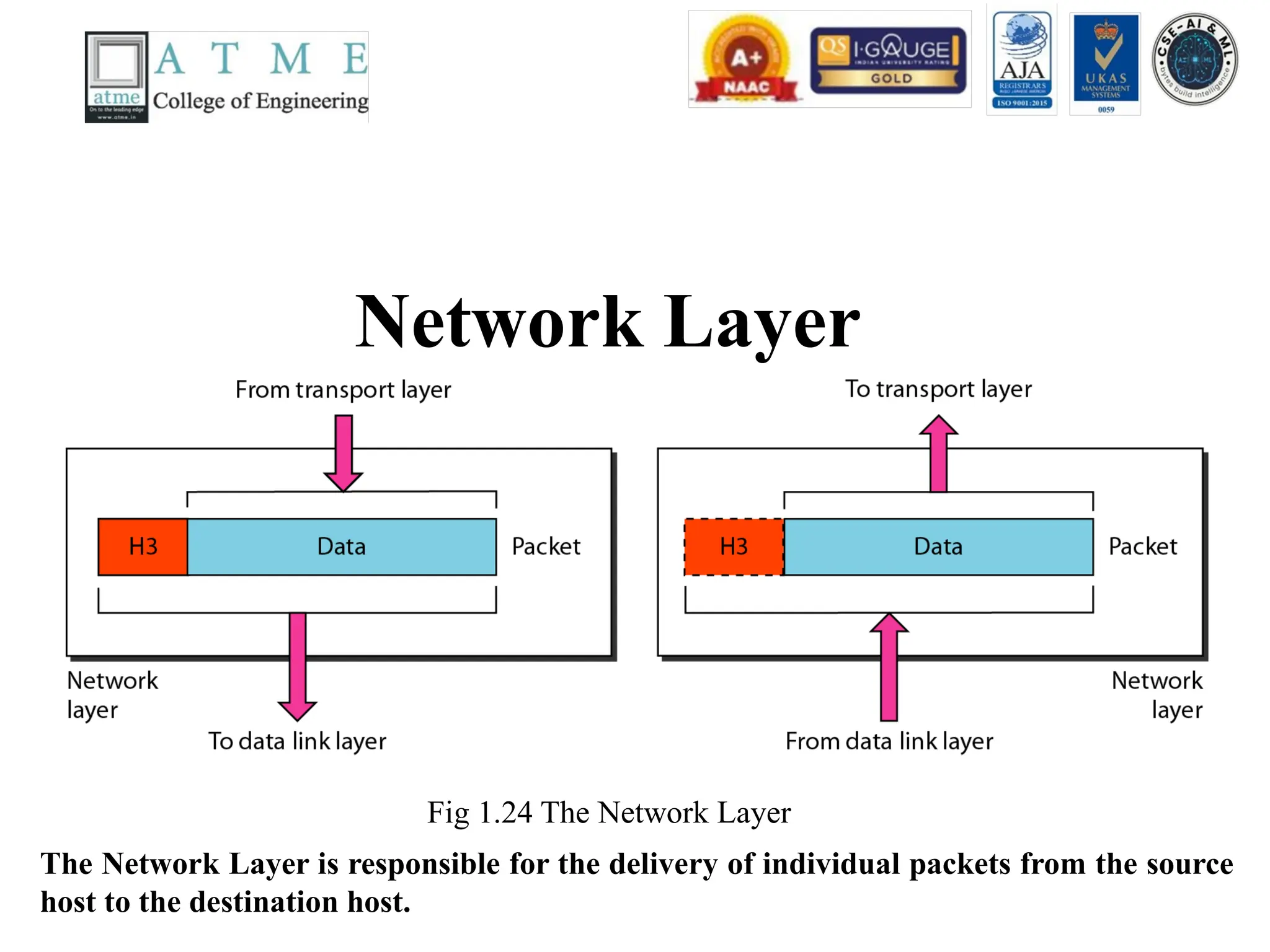
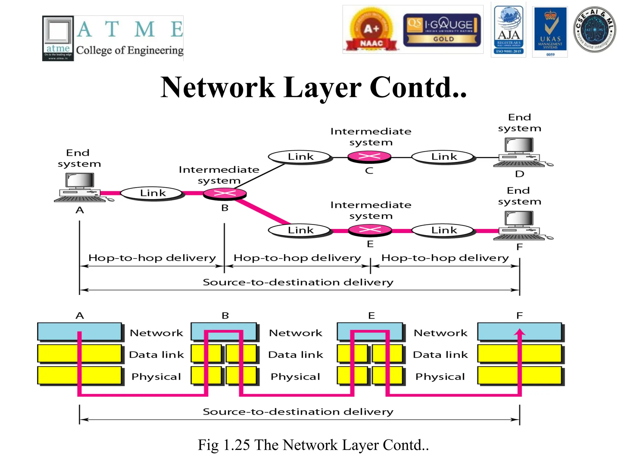
Network Layer
Fig 1.24The Network Layer
The Network Layer is responsible for the delivery of individual packets from the source
host to the destination host.
58.
Functionalities of NetworkLayer
• Following are the various functions performed by the network
layer of the OSI model.
• It translates logical network address into physical address.
Concerned with circuit, message or packet switching.
• Routers and gateways operate in the network layer. Mechanism is
provided by Network Layer for routing the packets to final
destination.
• Connection services are provided including network layer flow
control, network layer error control and packet sequence control.
• Breaks larger packets into small packets.
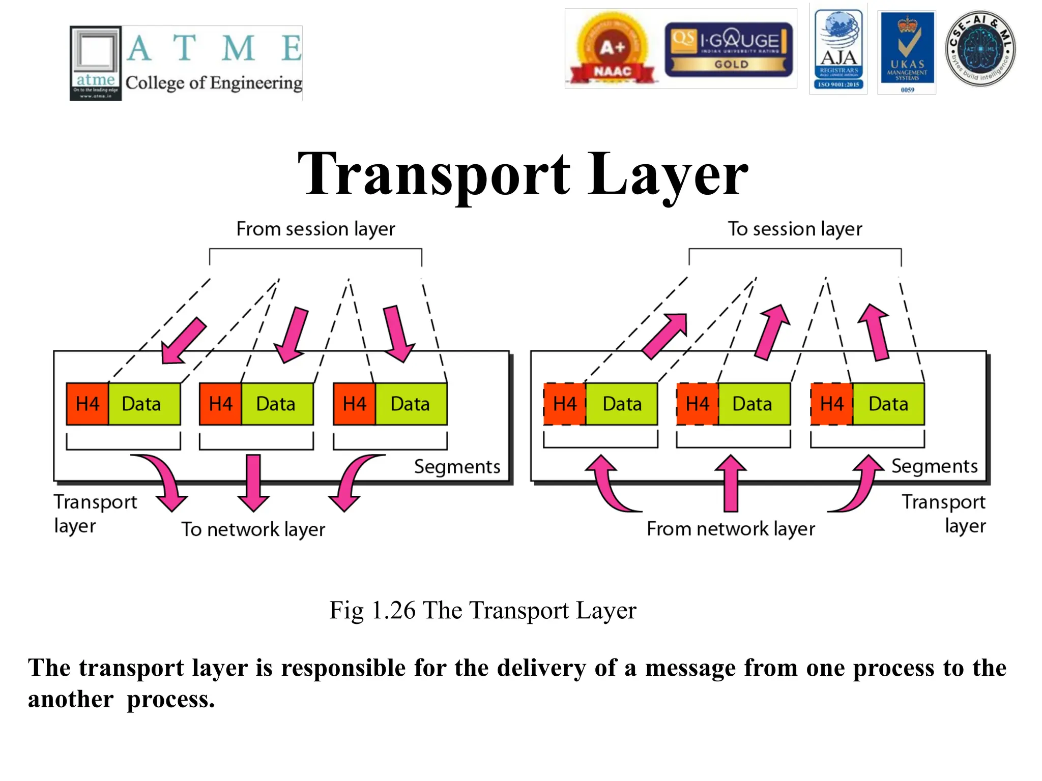
Transport Layer
Fig 1.26The Transport Layer
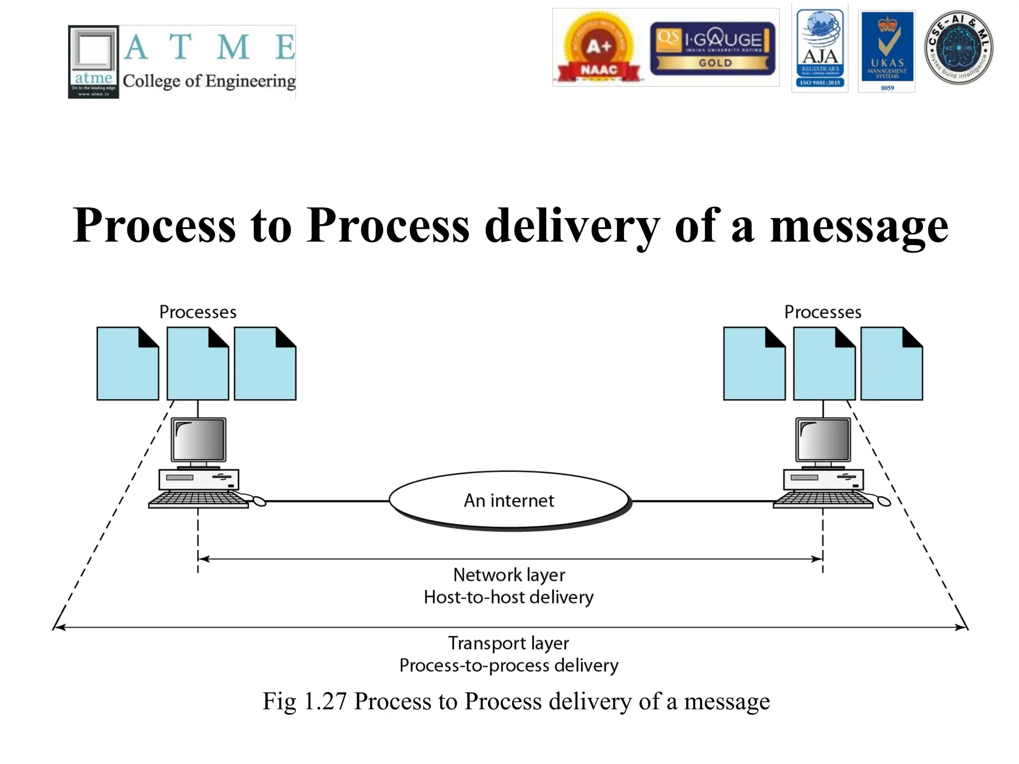
The transport layer is responsible for the delivery of a message from one process to the
another process.
61.
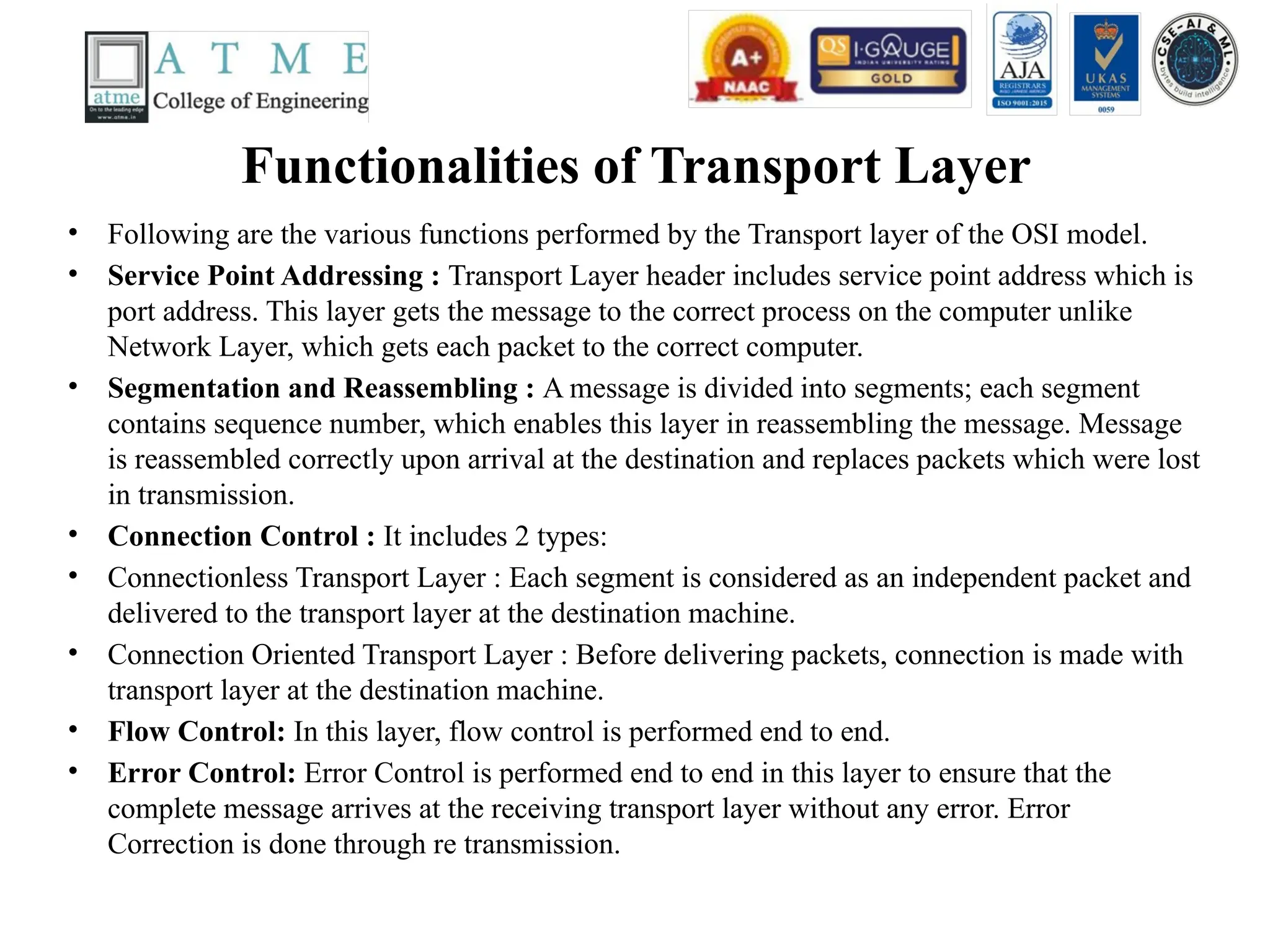
Functionalities of TransportLayer
• Following are the various functions performed by the Transport layer of the OSI model.
• Service Point Addressing : Transport Layer header includes service point address which is
port address. This layer gets the message to the correct process on the computer unlike
Network Layer, which gets each packet to the correct computer.
• Segmentation and Reassembling : A message is divided into segments; each segment
contains sequence number, which enables this layer in reassembling the message. Message
is reassembled correctly upon arrival at the destination and replaces packets which were lost
in transmission.
• Connection Control : It includes 2 types:
• Connectionless Transport Layer : Each segment is considered as an independent packet and
delivered to the transport layer at the destination machine.
• Connection Oriented Transport Layer : Before delivering packets, connection is made with
transport layer at the destination machine.
• Flow Control: In this layer, flow control is performed end to end.
• Error Control: Error Control is performed end to end in this layer to ensure that the
complete message arrives at the receiving transport layer without any error. Error
Correction is done through re transmission.
62.
Process to Processdelivery of a message
Fig 1.27 Process to Process delivery of a message
63.
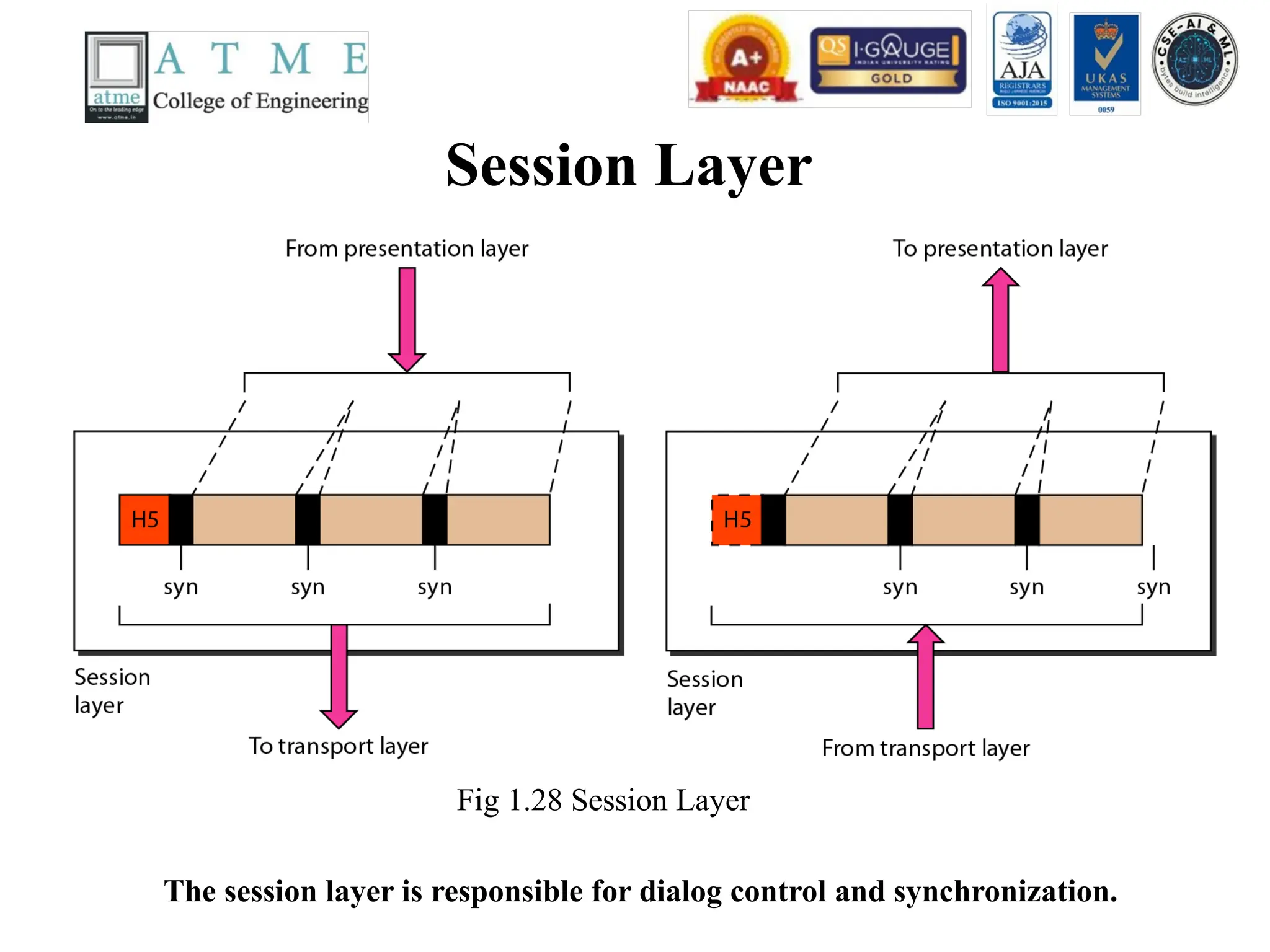
Session Layer
Fig 1.28Session Layer
The session layer is responsible for dialog control and synchronization.
64.
Functionalities of SessionLayer
• Following are the various functions performed by the session layer of the OSI
model.
• Dialog Control: This layer allows two systems to start communication with each
other in half-duplex or full-duplex.
• Token Management: This layer prevents two parties from attempting the same
critical operation at the same time.
• Synchronization:This layer allows a process to add check points which are
considered as synchronization points into stream of data. Example: If a system is
sending a file of 800pages, adding check points after every 50pages is
recommended. This ensures that 50 page unit is successfully received and
acknowledged. This is beneficial at the time of crash as if a crash happens at page
number110; there is no need to retransmit 1 to100 pages.
65.
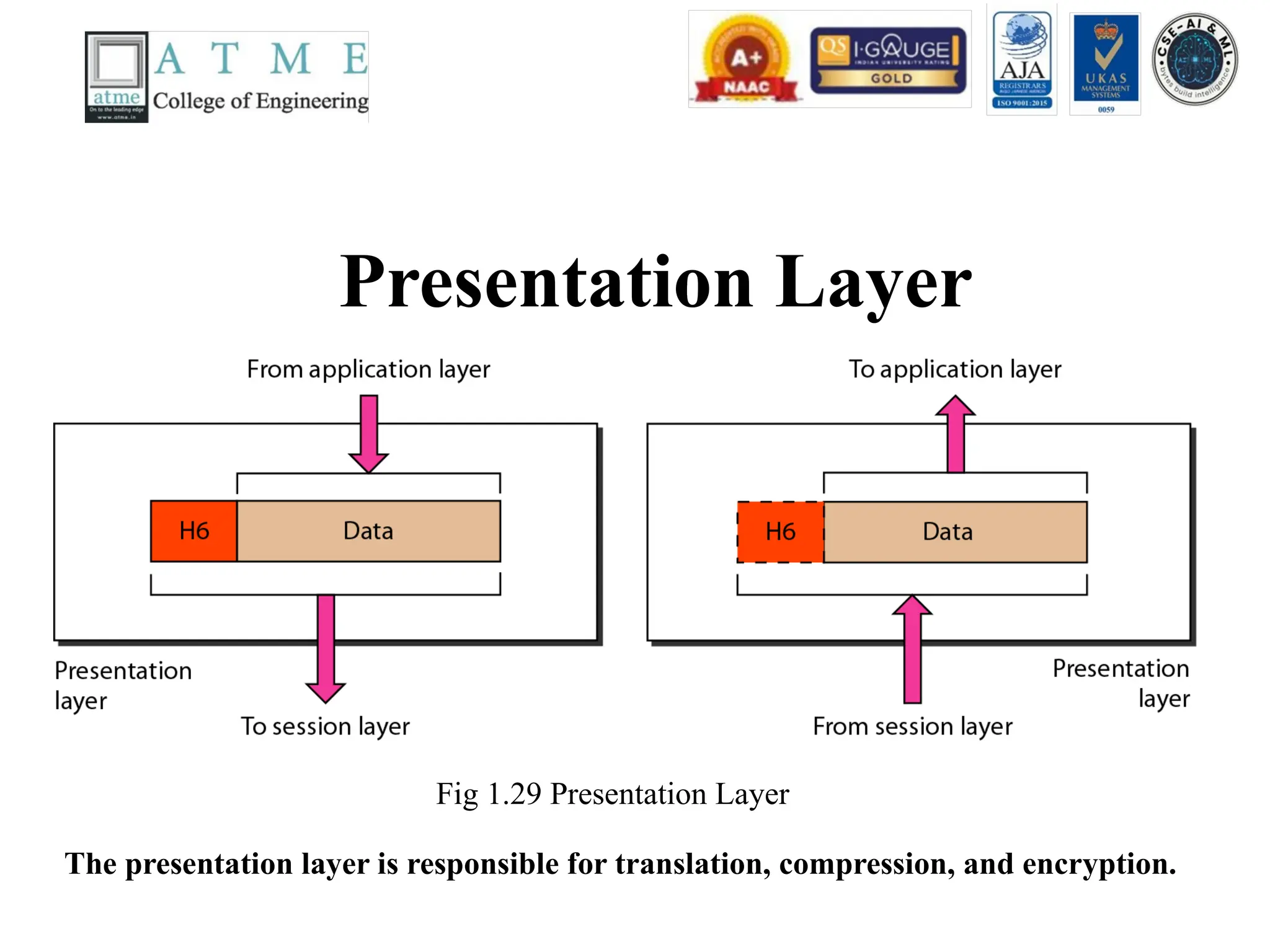
Presentation Layer
Fig 1.29Presentation Layer
The presentation layer is responsible for translation, compression, and encryption.
66.
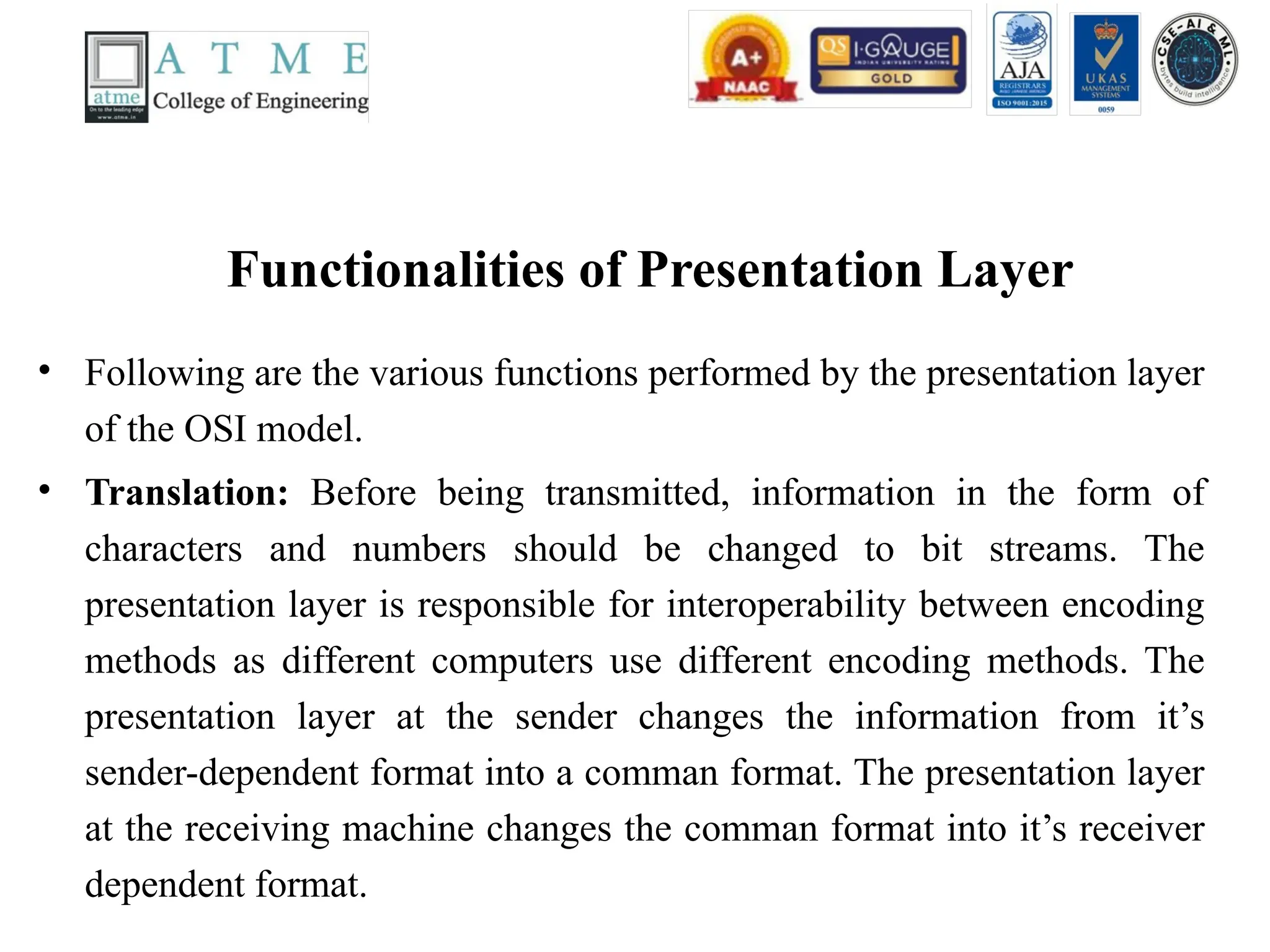
Functionalities of PresentationLayer
• Following are the various functions performed by the presentation layer
of the OSI model.
• Translation: Before being transmitted, information in the form of
characters and numbers should be changed to bit streams. The
presentation layer is responsible for interoperability between encoding
methods as different computers use different encoding methods. The
presentation layer at the sender changes the information from it’s
sender-dependent format into a comman format. The presentation layer
at the receiving machine changes the comman format into it’s receiver
dependent format.
67.
Contd..
• Encryption: Itcarries out encryption at the
transmitter and decryption at the receiver.
• Compression: It carries out data compression to
reduce the bandwidth of the data to be transmitted.
The primary role of Data compression is to reduce
the number of bits to be transmitted. It is important
in transmitting multi media such as audio, video, text
etc.
68.
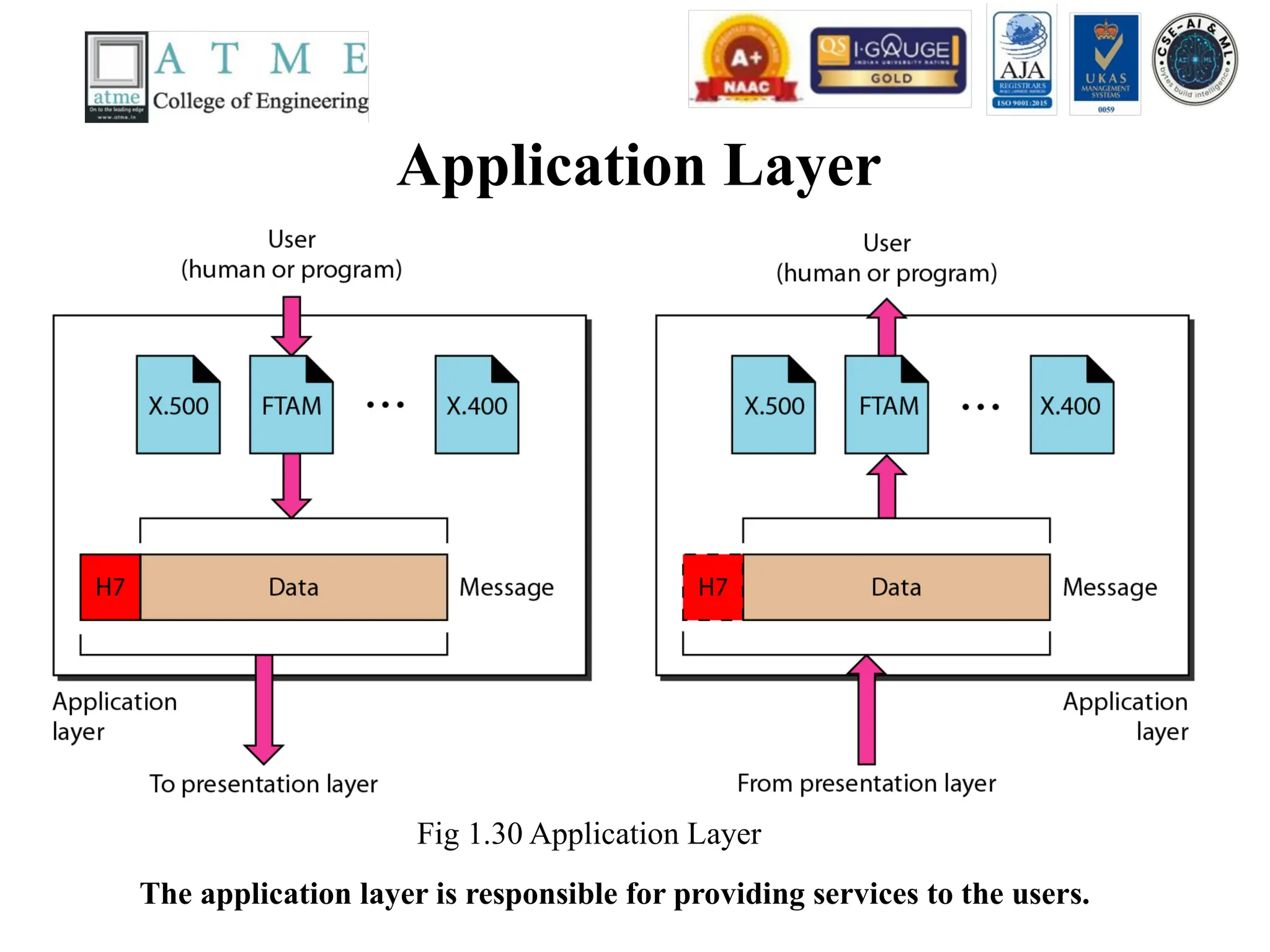
Application Layer
Fig 1.30Application Layer
The application layer is responsible for providing services to the users.
69.
Functionalities of ApplicationLayer
• Following are the various functions performed by the application layer of the
OSI model.
• Mail Services: This layer provides the basis for E-mail forwarding and storage.
• Network Virtual Terminal: It allows a user to log on to a remote host. The
application creates software emulation of a terminal at the remote host. User's
computer talks to the software terminal which in turn talks to the host and vice
versa. Then the remote host believes it is communicating with one of its own
terminals and allows user to log on.
• Directory Services: This layer provides access for global information about
various services.
• File Transfer, Access and Management (FTAM):It is a standard mechanism to
access files and manages it. Users can access files in a remote computer and
manage it. They can also retrieve files from a remote computer.
TCP/IP Protocol Suite
•The layers in the TCP/IP protocol suite do not
exactly match those in the OSI model. The
original TCP/IP protocol suite was defined as
having four layers: host-to-network, internet,
transport, and application. However, when
TCP/IP is compared to OSI, we can say that
the TCP/IP protocol suite is made of five
layers: physical, data link, network, transport,
and application.
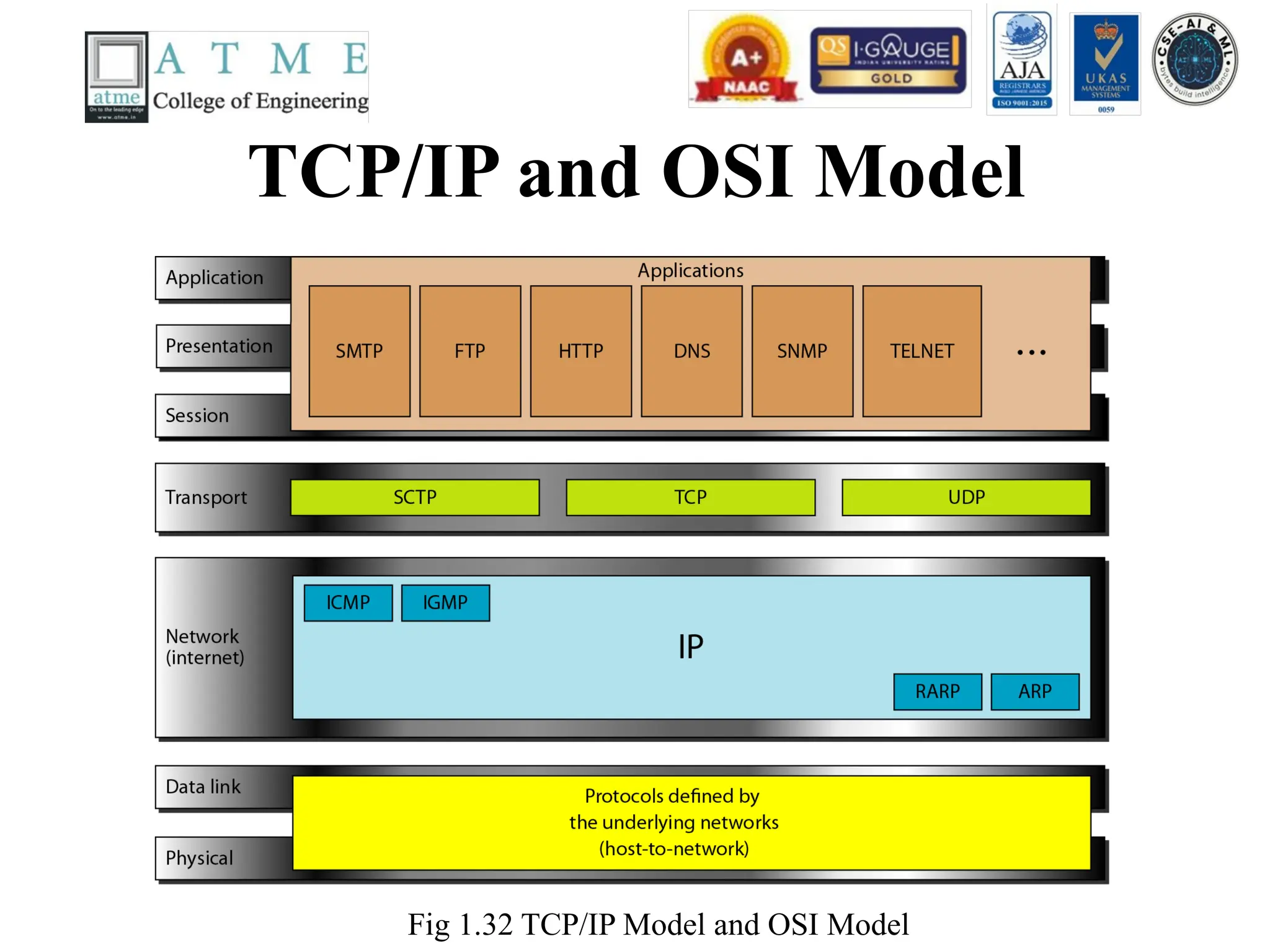
Contd..
• At thetransport layer, TCP/IP defines three
protocols : Transmission Control Protocol
(TCP), User Datagram Protocol (UDP), and
Stream Control Transmission Protocol
(STCP).
• At the network layer, the main protocol
defined by TCP/IP model is the
Internetworking protocol (IP).
74.
Contd..
• Physical andData Link Layers -
• At the physical and data link layers, TCP/IP does not define any
specific protocol. It supports all the standard and proprietary
protocols.
• Network Layer –
• At the network layer, TCP/IP supports the internetworking
protocol (IP). In turn, TCP/IP model supports four supporting
protocols namely ARP, ICMP, IGMP, RARP.
75.
Contd..
• Internetworking Protocol(IP) –
• The Internetworking protocol is the transmission mechanism
used by TCP/IP protocols. It is an unreliable and connectionless
protocol – a best effort delivery service. The term best effort
means that IP Provides no error checking or tracking.
• IP transports data in packets called datagrams, each of which is
transported separately. Datagrams can travel along different
routes and can arrive out of sequence or be duplicated. IP does
not keep track of the routes and has no facility for reordering
datagrams once they arrive at their destination.
76.
Contd..
• Address ResolutionProtocol (ARP) –
• The ARP is used to find the physical address of the
node when its internet address is known. On a typical
physical network, such as LAN, each device on a link
is identified by physical address, usually imprinted on
the network interface card (NIC).
• Reverse Address Resolution Protocol (RARP) –
• The RARP allows a host to discover it’s internet
address when it knows only the physical address. It is
used when it is connected to a computer for the first
time or when a diskless computer is booted.
77.
Contd..
• Internet ControlMessage Protocol (ICMP) –
• The ICMP is a mechanism used by hosts and
gateways to send notification of datagram
problems back to the sender. ICMP sends query
and error reporting messages.
• Internet Group Message Protocol (IGMP) –
• IGMP is used to facilitate the simultaneous
transmission of the message to a group of
recipients.
78.
Contd..
• Transport layer–
• The transport layer in the TCP/IP model is
represented by two protocols namely a)
Transmission Control Protocol (TCP) b) User
Datagram Protocol (UDP).
• IP is a host-to-host protocol meaning that it can
deliver a packet from one physical device to another
physical device.
• UDP and TCP are transport level protocols
responsible for delivery of a message from one
process to another process.
79.
Contd..
• User DatagramProtocol (UDP) –
• The UDP is the simpler of the two standard TCP/IP transport protocols. It
is a process-to-process protocol that adds only port addresses, checksum
error control, and length information to the data from the upper layer.
• Transmission Control Protocol (TCP) –
• The TCP provides full transport-layer services to applications. TCP is a
reliable stream transport protocol.
• For each transmission, TCP divides a stream of data into smaller units
called segments. Each segment includes a sequence number for reordering
after receipt, together with an acknowledgement number for the segments
received. Segments are carried across the internet inside of IP datagrams.
At the receiving end, TCP collects each datagram as it comes in and
reorders the transmission based on sequence numbers.
80.
Contd..
• Stream ControlTransmission Protocol (SCTP) –
• The SCTP provides support for newer
applications such as voice over the Internet. It is a
transport layer protocol the combines the best
features of UDP and TCP.
• Application Layer –
• The application layer in TCP/IP is equivalent to
the combined session, presentation, and
application layers in the OSI model.
81.
Application Layer Contd..
•The several protocols used in the application
layer are
• i) Simple mail transfer protocol (SMTP)
• ii) File Transfer Protocol (FTP)
• iii) Hyper Text Transfer Protocol (HTTP)
• iv) Domain Name System (DNS)
• v) Simple Network Management Protocol
(SNMP)
• vi) Teletype Network (TelNet)
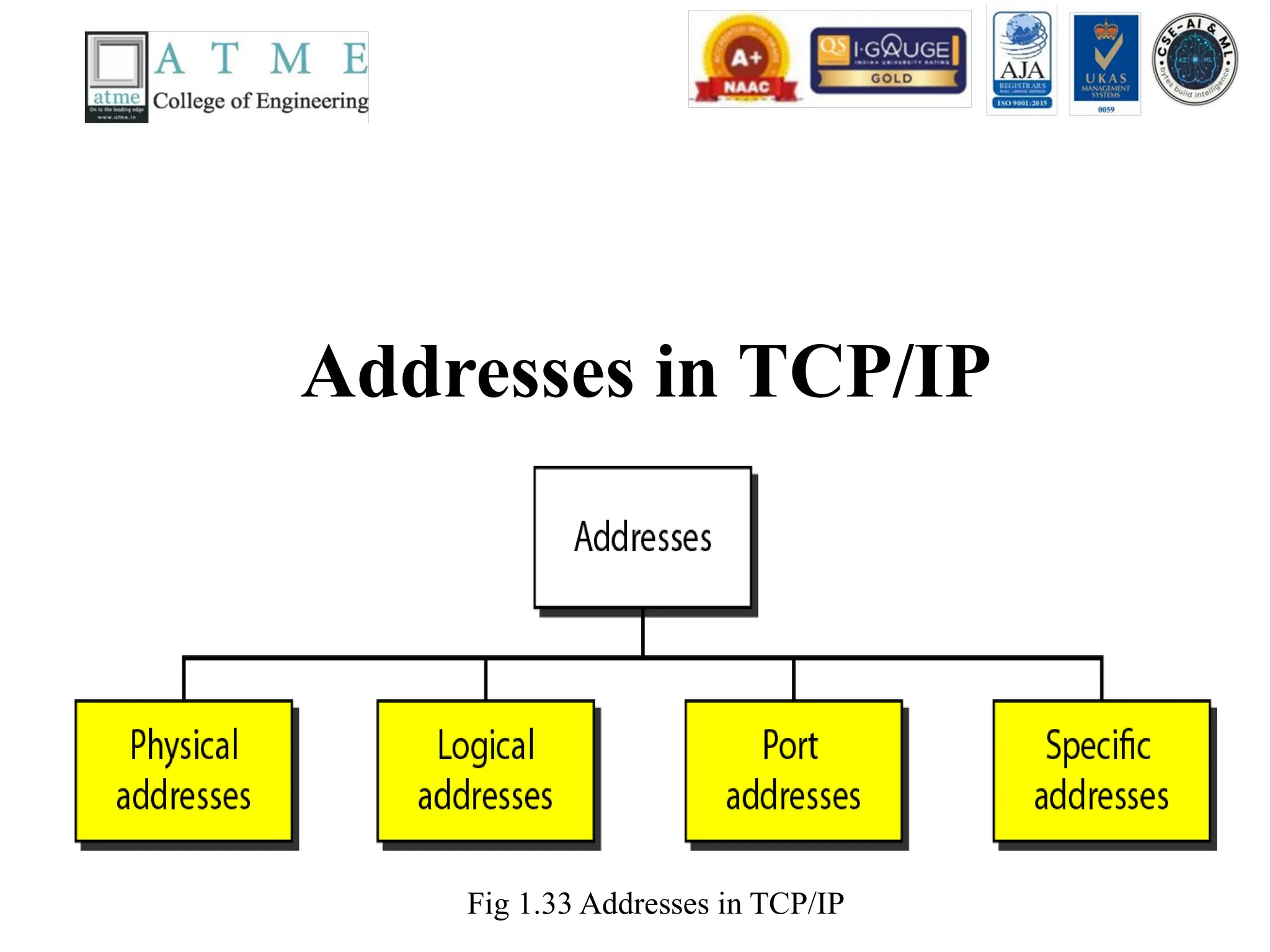
Addressing
• Four levelsof addresses are used in an internet
employing the TCP/IP protocols : physical,
logical, port, and specific.
• Topics discussed in this section :
• Physical Addresses
• Logical Addresses
• Port Addresses
• Specific Addresses
Physical Address
• Thephysical address, also known as the link address, is the
address of a node as defined by its LAN or WAN.
• The size and format of these addresses vary depending on the
network. For example, Ethernet uses a 6-byte (48-bit) physical
address.
• Physical addresses can be either unicast (one single recipient),
multi cast (a group of recipients), or broadcast (to be received by
all systems in the network.
• Example: Most local area networks use a 48-bit (6-byte) physical
address written as 12 hexa decimal digits; every byte (2
hexadecimal digits) is separated by a colon, as shown below: A6-
byte (12 hexadecimal digits) physical address 07:01:02:01:2C:4B
86.
Logical Addresses
• Logicaladdresses are used by networking software to allow packets to be independent of
the physical connection of the network, that is, to work with different network topologies
and types of media.
• A logical address in the Internet is currently a 32-bit/128-bit address that can uniquely
define a host connected to the Internet. An internet address in IPv4 in decimal
numbers132.24.75.9
• No two publicly addressed and visible hosts on the Internet can have the same IP address.
• The physical addresses will change from hop to hop, but the logical addresses remain the
same.
• The logical addresses can be either unicast (one single recipient), multicast (a group of
recipients),or broadcast (all systems in the network). There are limitations on broad cast
addresses.
87.
Port Addresses
• Thereare many application running on the computer. Each application run
with a port no.(logically)on the computer.
• A port number is part of the addressing information used to identify the
senders and receivers of messages.
• Port numbers are most commonly used with TCP/IP connections.
• These port numbers allow different applications on the same computer to
share network resources simultaneously.
• The physical addresses change from hop to hop, but the logical and port
addresses usually remain the same.
• Example: a port address is a 16-bit address represented by one decimal
number 753
88.
Specific Address
• Someapplications have user-friendly addresses
that are designed for that specific application.
• Examples include the e-mail address (for
example,narayan@daffodilvarsity.edu.bd)and
the Universal Resource Locator(URL) (for
example,www.daffodilvarsity.edu.bd). The first
defines the recipient of an e-mail; the second is
used to find a document on the World Wide Web.
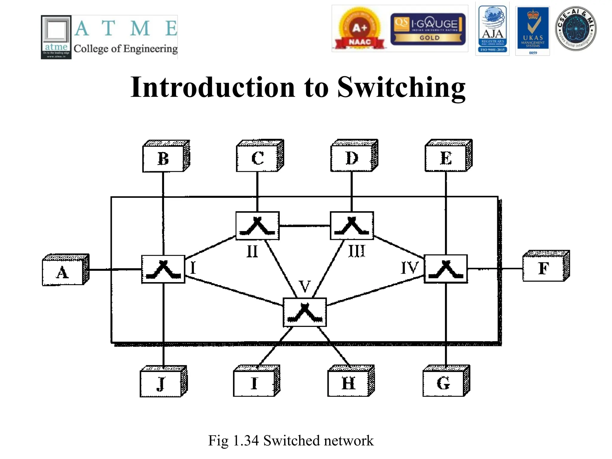
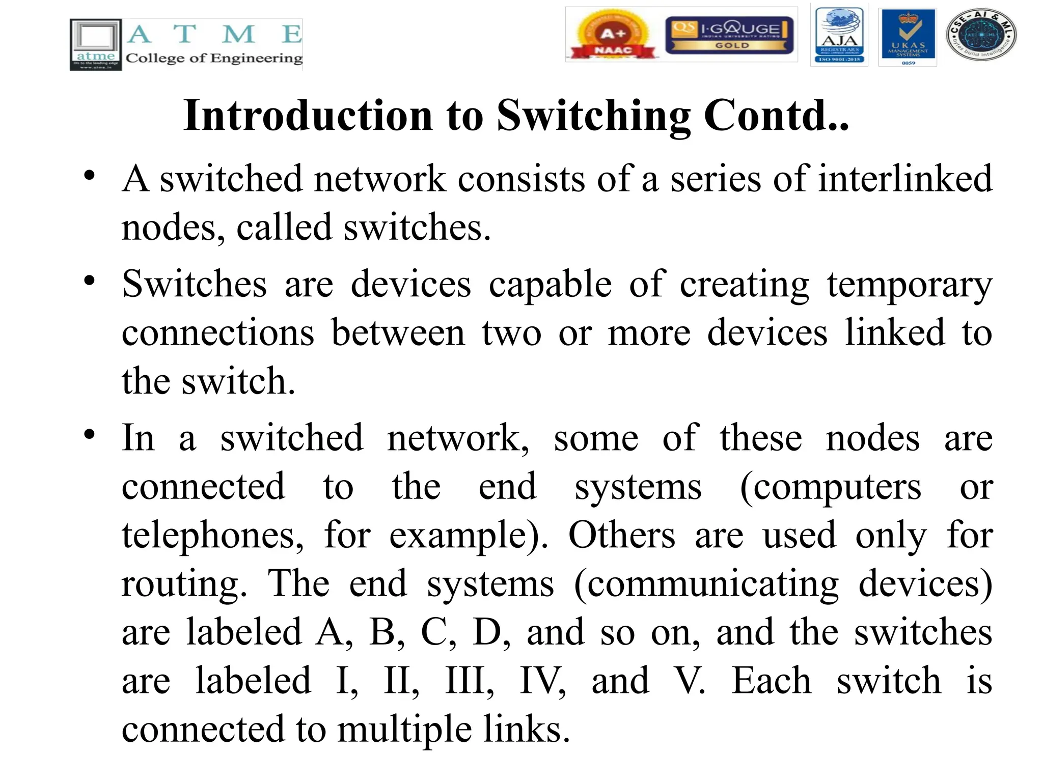
Introduction to SwitchingContd..
• A switched network consists of a series of interlinked
nodes, called switches.
• Switches are devices capable of creating temporary
connections between two or more devices linked to
the switch.
• In a switched network, some of these nodes are
connected to the end systems (computers or
telephones, for example). Others are used only for
routing. The end systems (communicating devices)
are labeled A, B, C, D, and so on, and the switches
are labeled I, II, III, IV, and V. Each switch is
connected to multiple links.
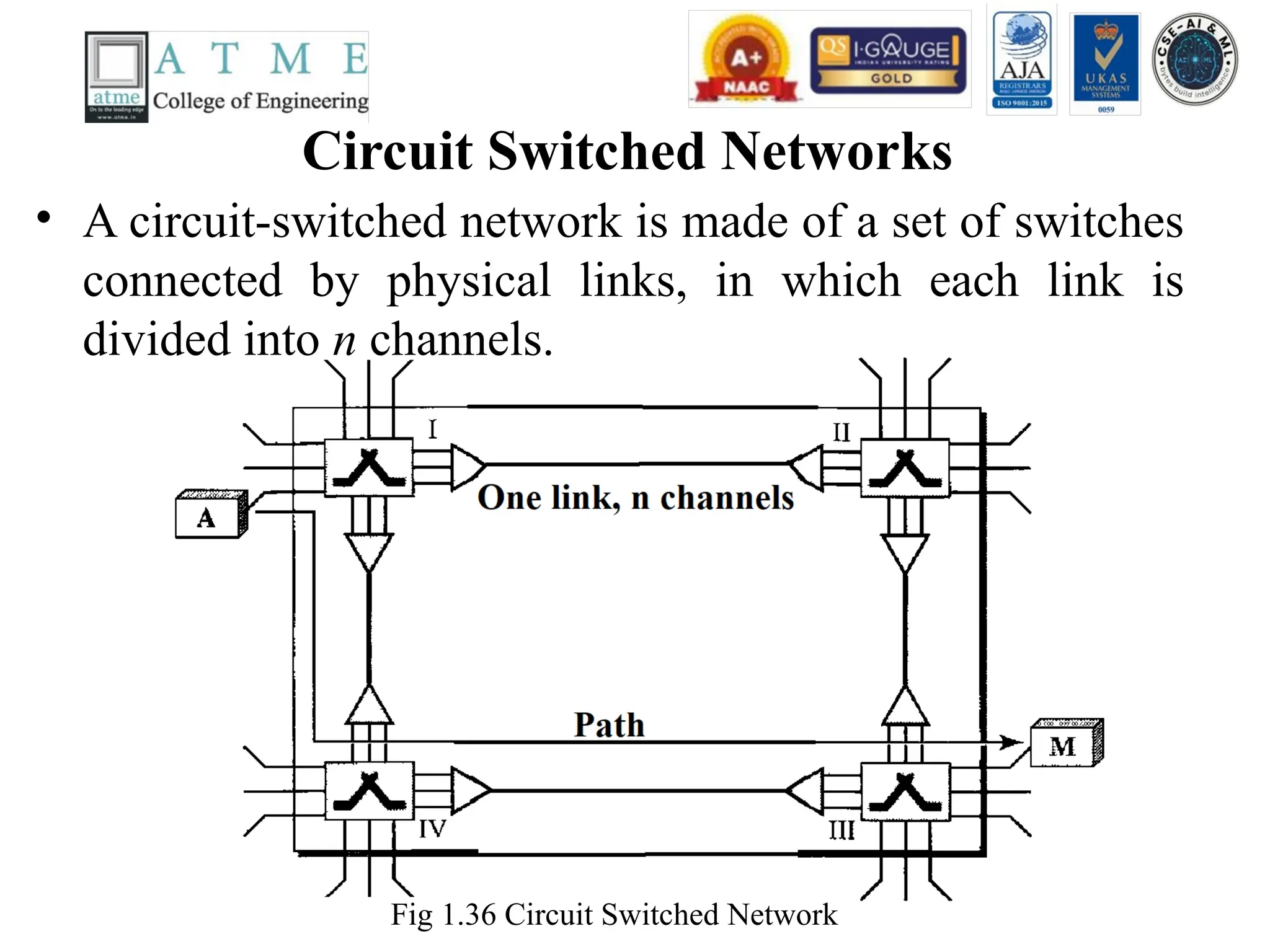
Circuit Switched Networks
•A circuit-switched network is made of a set of switches
connected by physical links, in which each link is
divided into n channels.
Fig 1.36 Circuit Switched Network
93.
Circuit Switched NetworksContd..
• Fig 1.36 shows a trivial circuit-switched network with four switches and
four links. Each link is divided into n (n is 3 in the figure) channels by
using FDM or TDM.
• We have explicitly shown the multiplexing symbols to emphasize the
division of the link into channels even though multiplexing can be
implicitly included in the switch fabric.
• The end systems, such as computers or telephones, are directly connected
to a switch. We have shown only two end systems for simplicity. When
end system A needs to communicate with end system M, system A needs
to request a connection to M that must be accepted by all switches as
well as by M itself. This is called the setup phase; a circuit (channel) is
reserved on each link, and the combination of circuits or channels defines
the dedicated path. After the dedicated path made of connected circuits
(channels) is established, data transfer can take place. After all data have
been transferred, the circuits are tom down.
94.
Circuit Switched NetworksContd…
• Circuit switching takes place at the physical layer.
• Before starting communication, the stations must make a reservation for the
resources to be used during the communication. These resources, such as
channels (bandwidth in FDM and time slots in TDM), switch buffers, switch
processing time, and switch input/output ports, must remain dedicated during
the entire duration of data transfer until the teardown phase.
• Data transferred between the two stations are not packetized (physical layer
transfer of the signal). The data are a continuous flow sent by the source station
and received by the destination station, although there may be periods of
silence.
• There is no addressing involved during data transfer. The switches route the
data based on their occupied band (FDM) or time slot (TDM).
• In circuit switching, the resources need to be reserved during the setup phase;
the resources remain dedicated for the entire duration of data transfer until the
teardown phase.
95.
• Three Phasesin Circuit Switched Network
• The actual communication in a circuit-switched network requires three phases: connection setup, data
transfer, and connection teardown.
• Setup Phase
• Before the two parties (or multiple parties in a conference call) can communicate, a dedicated
circuit (combination of channels in links) needs to be established.
• The end systems are normally connected through dedicated lines to the switches, so
connection setup means creating dedicated channels between the switches. For example, in
Figure 1.36, when system A needs to connect to system M, it sends a setup request that
includes the address of system M, to switch I. Switch I finds a channel between itself and
switch IV that can be dedicated for this purpose.
• Switch I then sends the request to switch IV, which finds a dedicated channel between itself
and switch III. Switch III informs system M of system A's intention at this time. In the next
step to making a connection, an acknowledgment from system M needs to be sent in the
opposite direction to system A.
• Only after system A receives this acknowledgment is the connection established. Note that
end-to-end addressing is required for creating a connection between the two end systems.
These can be, for example, the addresses of the computers assigned by the administrator in a
TDM network, or telephone numbers in an FDM network.
96.
• Data TransferPhase
• After the establishment of the dedicated circuit (channels),
the two parties can transfer data.
• Teardown Phase
• When one of the parties needs to disconnect, a signal is sent
to each switch to release the resources.
97.
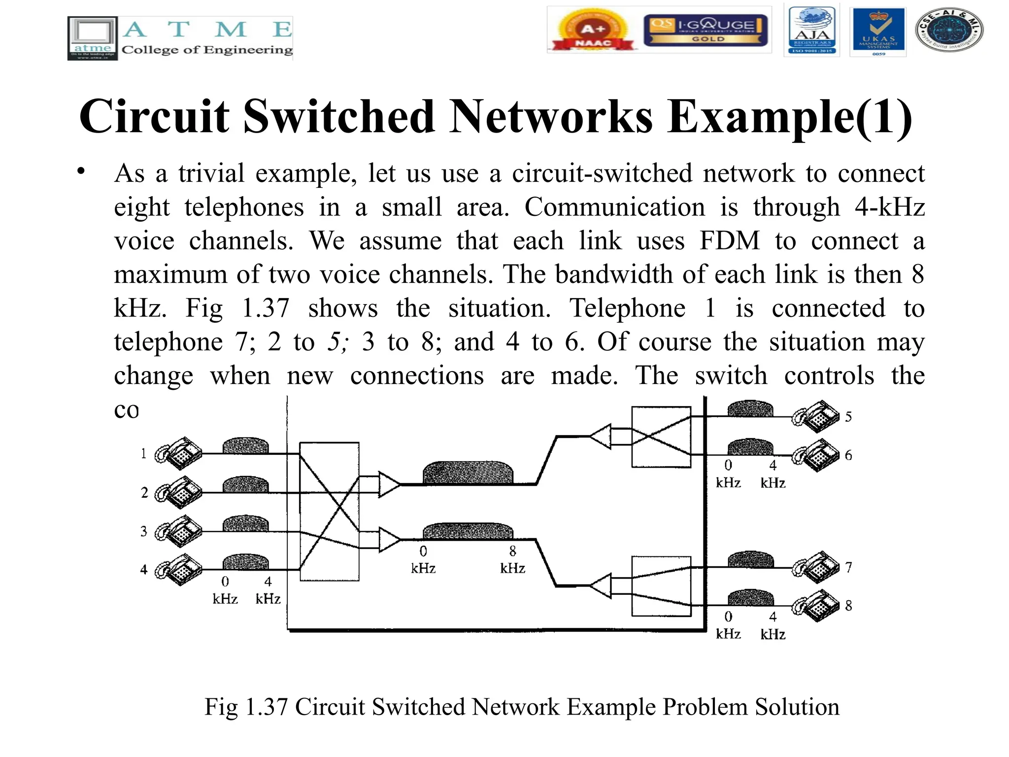
Circuit Switched NetworksExample(1)
• As a trivial example, let us use a circuit-switched network to connect
eight telephones in a small area. Communication is through 4-kHz
voice channels. We assume that each link uses FDM to connect a
maximum of two voice channels. The bandwidth of each link is then 8
kHz. Fig 1.37 shows the situation. Telephone 1 is connected to
telephone 7; 2 to 5; 3 to 8; and 4 to 6. Of course the situation may
change when new connections are made. The switch controls the
connections.
Fig 1.37 Circuit Switched Network Example Problem Solution
98.
Datagram Networks
• Indata communications, we need to send messages from one end
system to another. If the message is going to pass through a packet-
switched network, it needs to be divided into packets of fixed or
variable size. The size of the packet is determined by the network and
the governing protocol.
• In packet switching, there is no resource allocation for a packet. This
means that there is no reserved bandwidth on the links, and there is no
scheduled processing time for each packet. Resources are allocated on
demand. The allocation is done on a firstcome, first-served basis.
When a switch receives a packet, no matter what is the source or
destination, the packet must wait if there are other packets being
processed.
• As with other systems in our daily life, this lack of reservation may
create delay. For example, if we do not have a reservation at a
restaurant, we might have to wait.
99.
• In apacket-switched network, there is no resource
reservation; resources are allocated on demand.
• In a datagram network, each packet is treated
independently of all others. Even if a packet is part
of a multi packet transmission, the network treats it
as though it existed alone. Packets in this approach
are referred to as datagrams.
• Datagram switching is normally done at the network
layer.
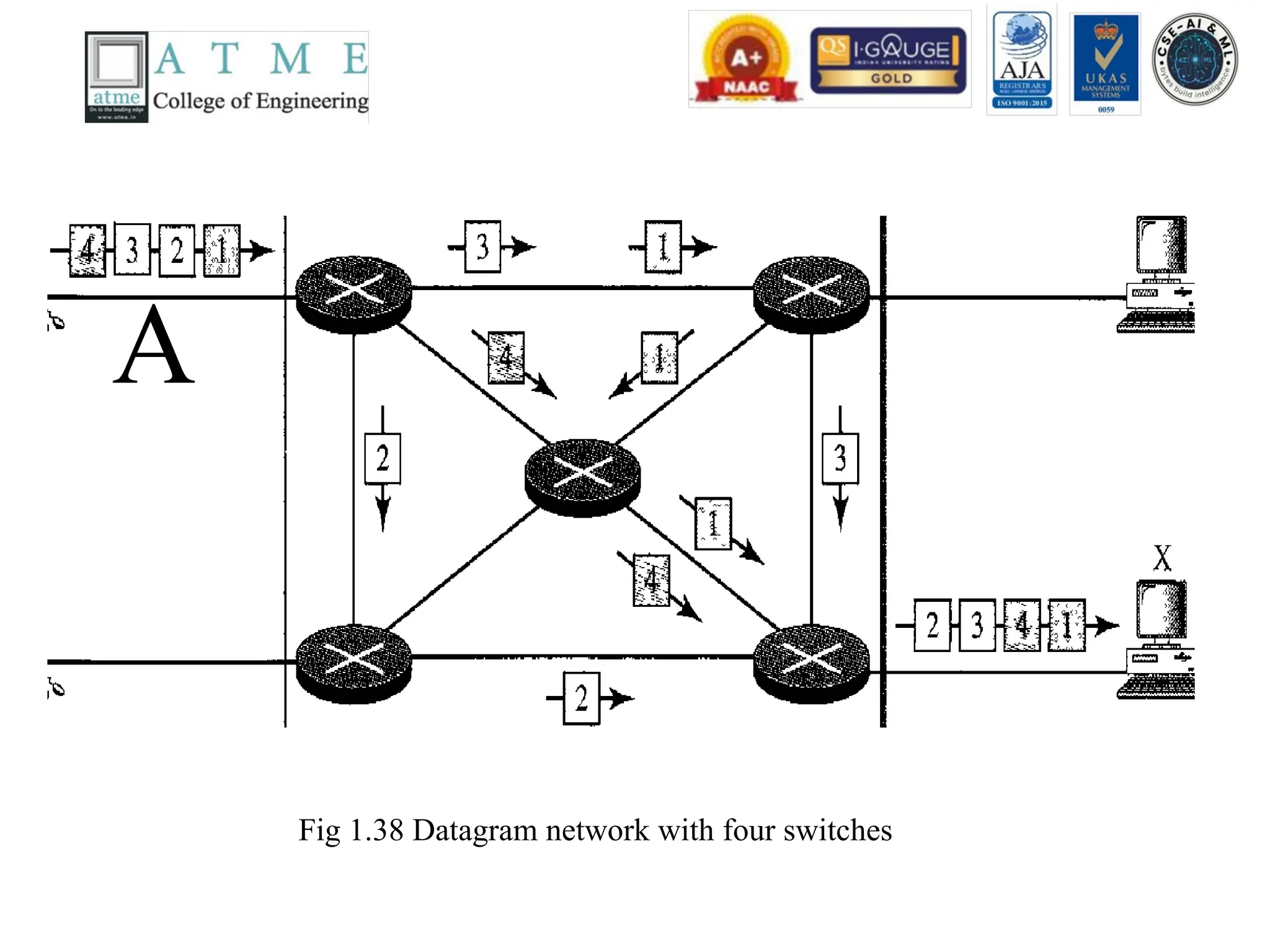
• Fig 1.38 shows how the datagram approach is used to
deliver four packets from station A to station X.
• In thisexample, all four packets (or datagrams) belong
to the same message, but may travel different paths to
reach their destination. This is so because the links may
be involved in carrying packets from other sources and
do not have the necessary bandwidth available to carry
all the packets from A to X. This approach can cause the
datagrams of a transmission to arrive at their destination
out of order with different delays between the packets.
Packets may also be lost or dropped because of a lack of
resources. In most protocols, it is the responsibility of an
upper-layer protocol to reorder the datagrams or ask for
lost datagrams before passing them on to the application.
102.
Routing Table inDatagram Networks
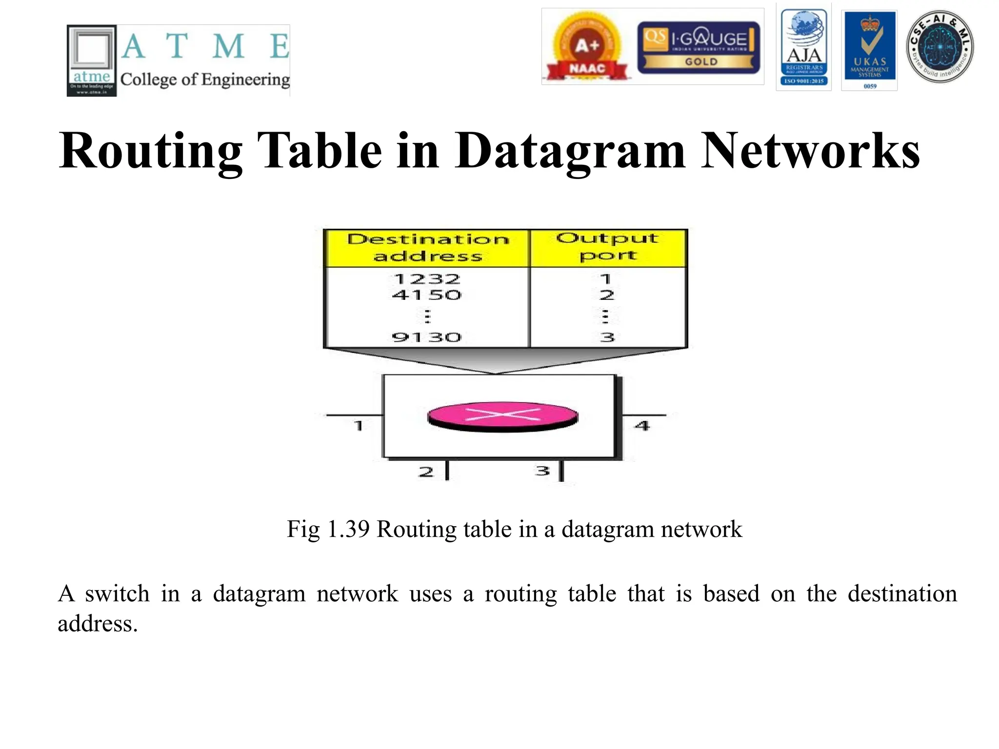
Fig 1.39 Routing table in a datagram network
A switch in a datagram network uses a routing table that is based on the destination
address.
103.
• Destination Address
•Every packet in a datagram network carries a header that contains,
among other information, the destination address of the packet.
When the switch receives the packet, this destination address is
examined; the routing table is consulted to find the corresponding
port through which the packet should be forwarded. This address,
unlike the address in a virtual-circuit-switched network, remains
the same during the entire journey of the packet.
• The destination address in the header of a packet in a datagram
network remains the same during the entire journey of the packet.
104.
Virtual Circuit Networks
•A virtual-circuit network is a cross between a circuit-switched network
and a datagram network. It has some characteristics of both.
• As in a circuit-switched network, there are setup and teardown phases
in addition to the data transfer phase.
• Resources can be allocated during the setup phase, as in a circuit-
switched network, or on demand, as in a datagram network.
• As in a datagram network, data are packetized and each packet carries
an address in the header. However, the address in the header has local
jurisdiction (it defines what should be the next switch and the channel
on which the packet is being carried), not end-to-end jurisdiction. The
reader may ask how the intermediate switches know where to send the
packet if there is no final destination address carried by a packet.
105.
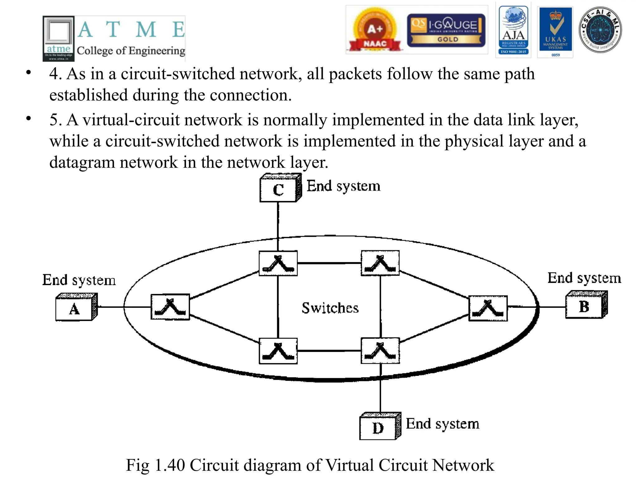
• 4. Asin a circuit-switched network, all packets follow the same path
established during the connection.
• 5. A virtual-circuit network is normally implemented in the data link layer,
while a circuit-switched network is implemented in the physical layer and a
datagram network in the network layer.
Fig 1.40 Circuit diagram of Virtual Circuit Network
106.
• Figure 1.40is an example of a virtual-circuit network. The network has
switches that allow traffic from sources to destinations. A source or destination
can be a computer, packet switch, bridge, or any other device that connects
other networks.
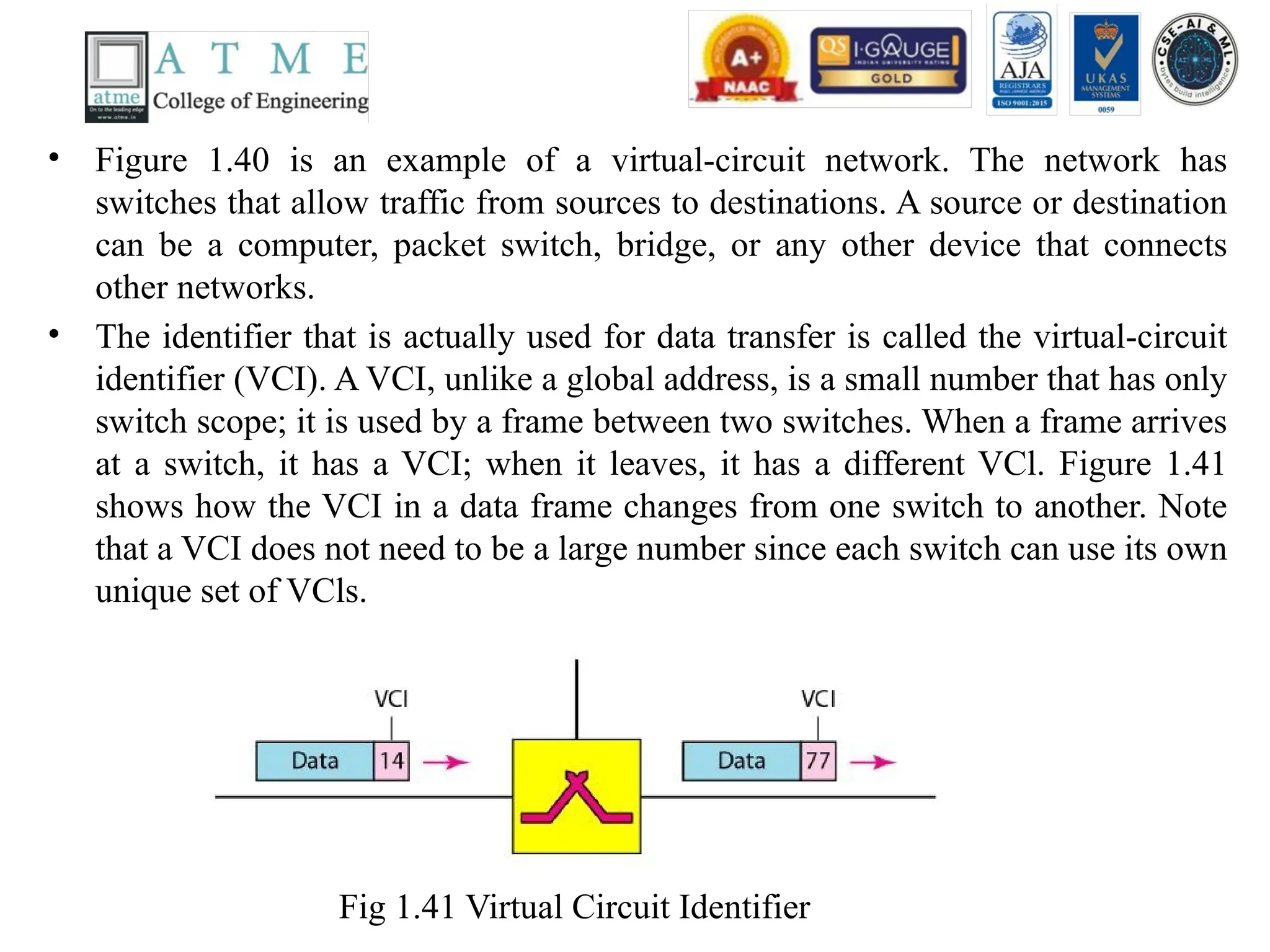
• The identifier that is actually used for data transfer is called the virtual-circuit
identifier (VCI). A VCI, unlike a global address, is a small number that has only
switch scope; it is used by a frame between two switches. When a frame arrives
at a switch, it has a VCI; when it leaves, it has a different VCl. Figure 1.41
shows how the VCI in a data frame changes from one switch to another. Note
that a VCI does not need to be a large number since each switch can use its own
unique set of VCls.
Fig 1.41 Virtual Circuit Identifier
107.
• Three Phases
•As in a circuit-switched network, a source and destination need to go
through three phases in a virtual-circuit network: setup, data transfer,
and teardown. In the setup phase, the source and destination use their
global addresses to help switches make table entries for the connection.
In the teardown phase, the source and destination inform the switches to
delete the corresponding entry. Data transfer occurs between these two
phases. We first discuss the data transfer phase, which is more
straightforward; we then talk about the setup and teardown phases.
• Data Transfer Phase
• To transfer a frame from a source to its destination, all switches need to
have a table entry for this virtual circuit. The table, in its simplest form,
has four columns. This means that the switch holds four pieces of
information for each virtual circuit that is already set up. We show later
how the switches make their table entries, but for the moment we
assume that each switch has a table with entries for all active virtual
circuits. Figure 1.42 shows such a switch and its corresponding table.
108.
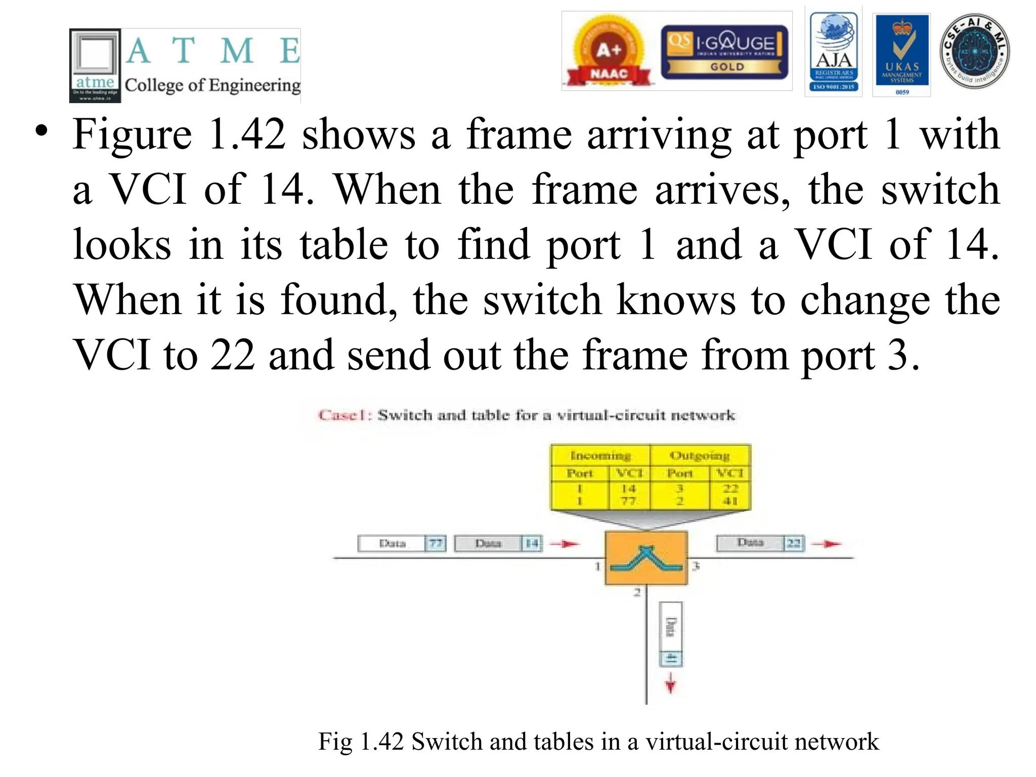
• Figure 1.42shows a frame arriving at port 1 with
a VCI of 14. When the frame arrives, the switch
looks in its table to find port 1 and a VCI of 14.
When it is found, the switch knows to change the
VCI to 22 and send out the frame from port 3.
Fig 1.42 Switch and tables in a virtual-circuit network
109.
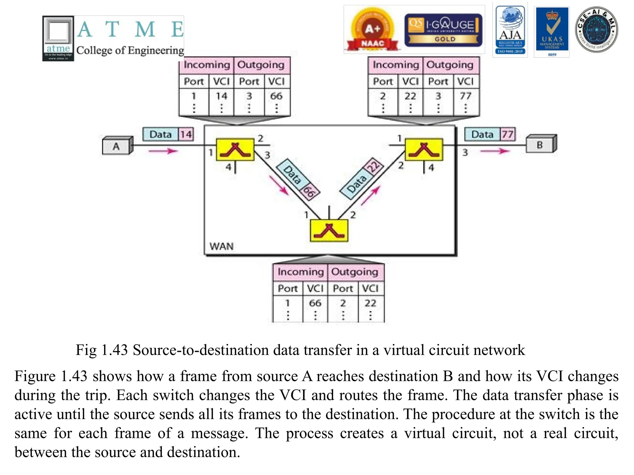
Fig 1.43 Source-to-destinationdata transfer in a virtual circuit network
Figure 1.43 shows how a frame from source A reaches destination B and how its VCI changes
during the trip. Each switch changes the VCI and routes the frame. The data transfer phase is
active until the source sends all its frames to the destination. The procedure at the switch is the
same for each frame of a message. The process creates a virtual circuit, not a real circuit,
between the source and destination.
110.
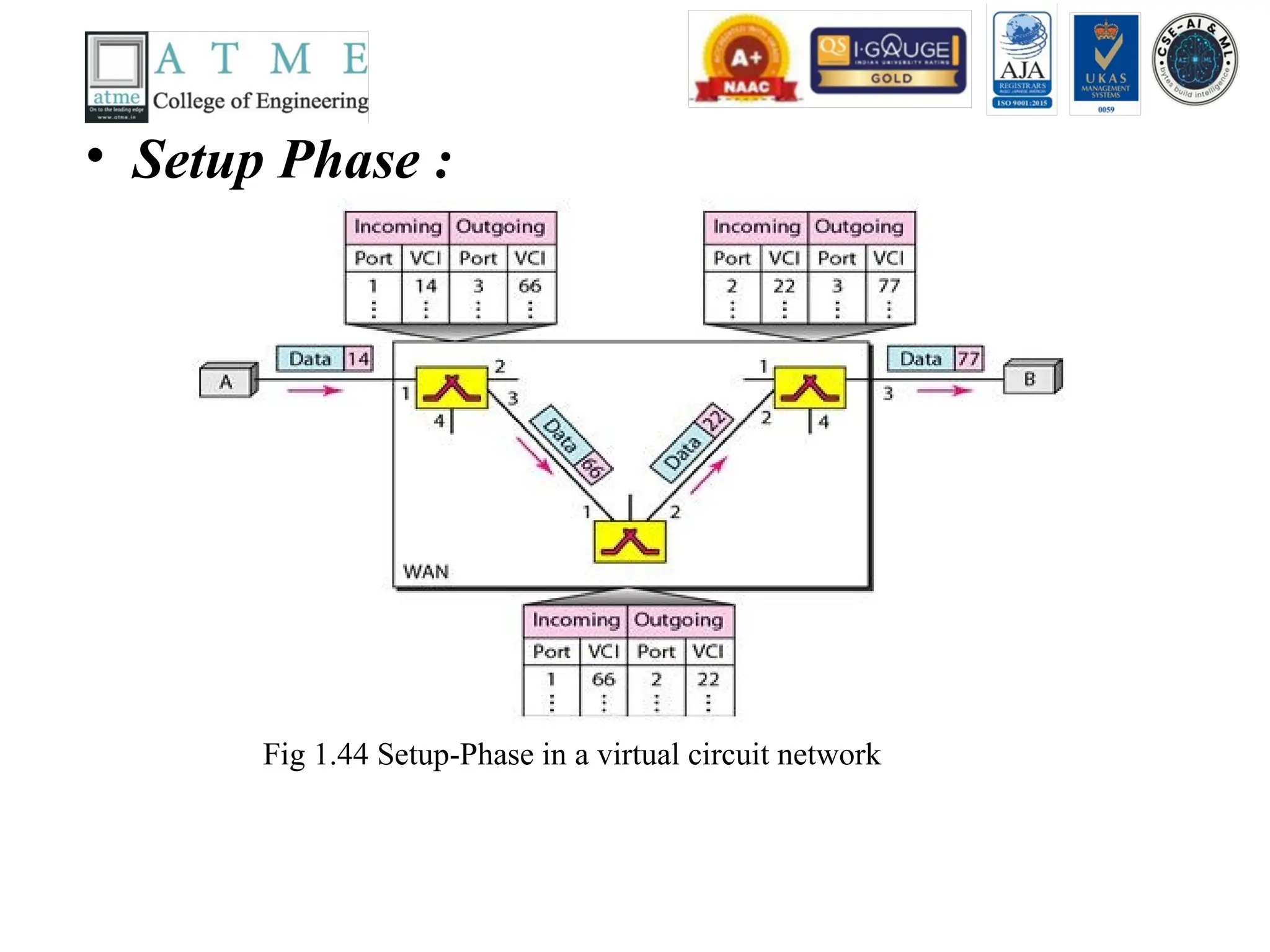
• Setup Phase:
Fig 1.44 Setup-Phase in a virtual circuit network
111.
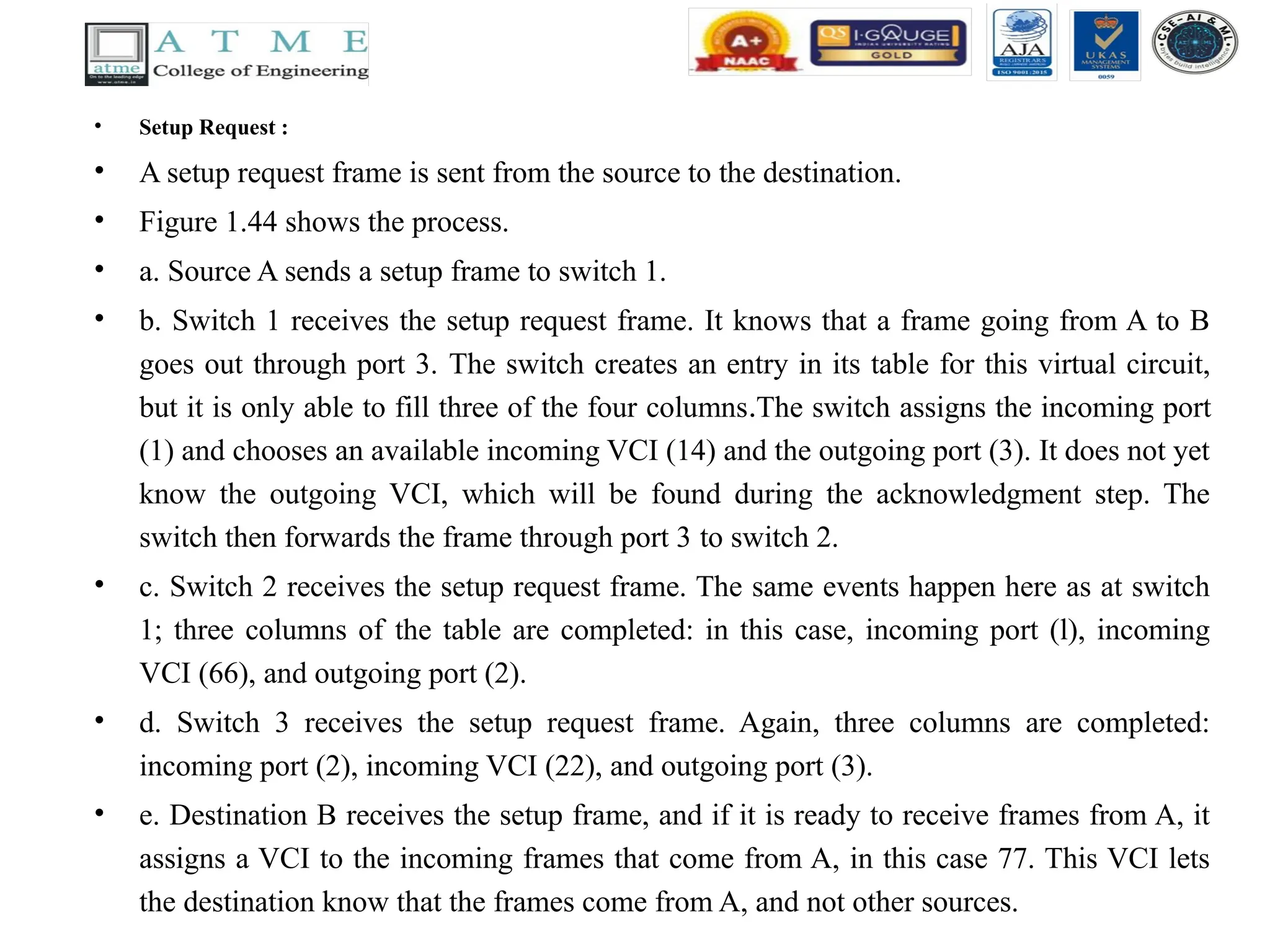
• Setup Request:
• A setup request frame is sent from the source to the destination.
• Figure 1.44 shows the process.
• a. Source A sends a setup frame to switch 1.
• b. Switch 1 receives the setup request frame. It knows that a frame going from A to B
goes out through port 3. The switch creates an entry in its table for this virtual circuit,
but it is only able to fill three of the four columns.The switch assigns the incoming port
(1) and chooses an available incoming VCI (14) and the outgoing port (3). It does not yet
know the outgoing VCI, which will be found during the acknowledgment step. The
switch then forwards the frame through port 3 to switch 2.
• c. Switch 2 receives the setup request frame. The same events happen here as at switch
1; three columns of the table are completed: in this case, incoming port (l), incoming
VCI (66), and outgoing port (2).
• d. Switch 3 receives the setup request frame. Again, three columns are completed:
incoming port (2), incoming VCI (22), and outgoing port (3).
• e. Destination B receives the setup frame, and if it is ready to receive frames from A, it
assigns a VCI to the incoming frames that come from A, in this case 77. This VCI lets
the destination know that the frames come from A, and not other sources.
112.
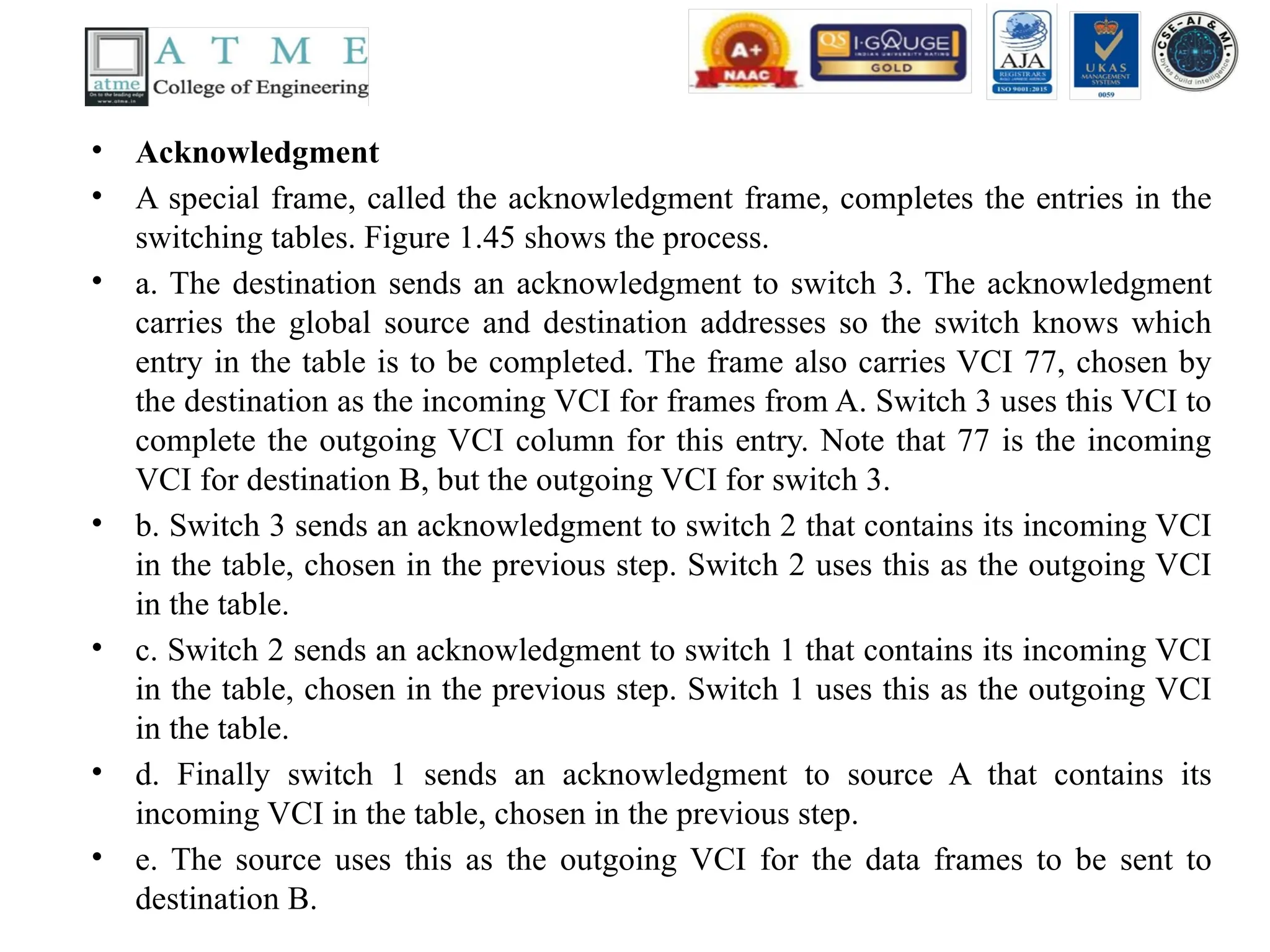
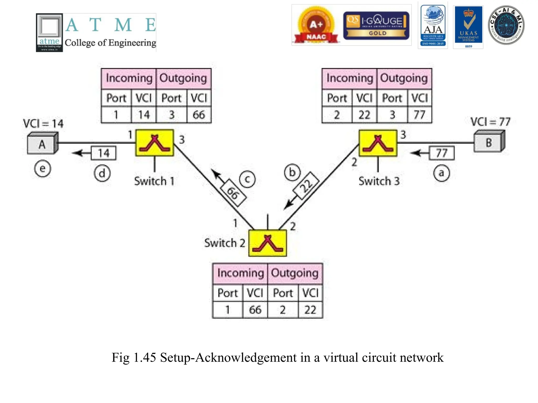
• Acknowledgment
• Aspecial frame, called the acknowledgment frame, completes the entries in the
switching tables. Figure 1.45 shows the process.
• a. The destination sends an acknowledgment to switch 3. The acknowledgment
carries the global source and destination addresses so the switch knows which
entry in the table is to be completed. The frame also carries VCI 77, chosen by
the destination as the incoming VCI for frames from A. Switch 3 uses this VCI to
complete the outgoing VCI column for this entry. Note that 77 is the incoming
VCI for destination B, but the outgoing VCI for switch 3.
• b. Switch 3 sends an acknowledgment to switch 2 that contains its incoming VCI
in the table, chosen in the previous step. Switch 2 uses this as the outgoing VCI
in the table.
• c. Switch 2 sends an acknowledgment to switch 1 that contains its incoming VCI
in the table, chosen in the previous step. Switch 1 uses this as the outgoing VCI
in the table.
• d. Finally switch 1 sends an acknowledgment to source A that contains its
incoming VCI in the table, chosen in the previous step.
• e. The source uses this as the outgoing VCI for the data frames to be sent to
destination B.
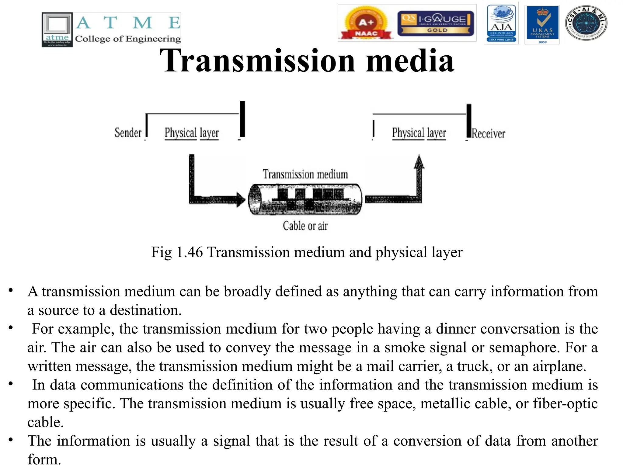
Transmission media
Fig 1.46Transmission medium and physical layer
• A transmission medium can be broadly defined as anything that can carry information from
a source to a destination.
• For example, the transmission medium for two people having a dinner conversation is the
air. The air can also be used to convey the message in a smoke signal or semaphore. For a
written message, the transmission medium might be a mail carrier, a truck, or an airplane.
• In data communications the definition of the information and the transmission medium is
more specific. The transmission medium is usually free space, metallic cable, or fiber-optic
cable.
• The information is usually a signal that is the result of a conversion of data from another
form.
115.
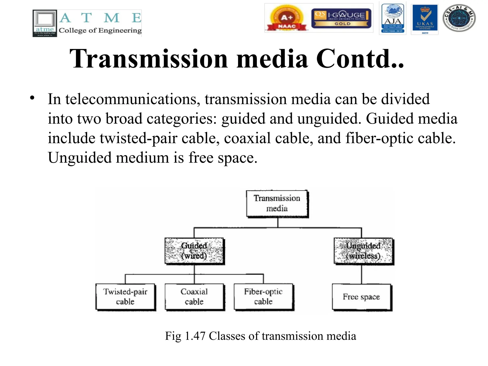
Transmission media Contd..
•In telecommunications, transmission media can be divided
into two broad categories: guided and unguided. Guided media
include twisted-pair cable, coaxial cable, and fiber-optic cable.
Unguided medium is free space.
Fig 1.47 Classes of transmission media
116.
Transmission media Contd..
•GUIDED MEDIA
• Guided media, which are those that provide a conduit from
one device to another, include twisted-pair cable, coaxial
cable, and fiber-optic cable.
• A signal traveling along any of these media is directed and
contained by the physical limits of the medium.
• Twisted-pair and coaxial cable use metallic (copper)
conductors that accept and transport signals in the form of
electric current.
• Optical fiber is a cable that accepts and transports signals in
the form of light.
117.
Transmission media Contd..
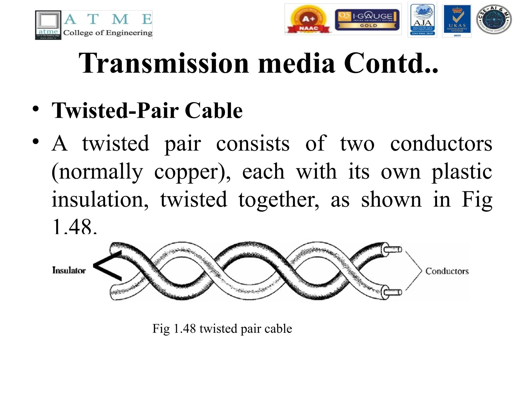
•Twisted-Pair Cable
• A twisted pair consists of two conductors
(normally copper), each with its own plastic
insulation, twisted together, as shown in Fig
1.48.
Fig 1.48 twisted pair cable
118.
Twisted-Pair Cable
contd..
• Oneof the wires is used to carry signals to the receiver, and the
other is used only as a ground reference.
• The receiver uses the difference between the two. In addition to the
signal sent by the sender on one of the wires, interference (noise)
and crosstalk may affect both wires and create unwanted signals.
• If the two wires are parallel, the effect of these unwanted signals is
not the same in both wires because they are at different locations
relative to the noise or crosstalk sources (e,g., one is closer and the
other is farther). This results in a difference at the receiver.
• By twisting the pairs, a balance is maintained. For example,
suppose in one twist, one wire is closer to the noise source and the
other is farther; in the next twist, the reverse is true.
119.
Twisted-Pair Cable
contd..
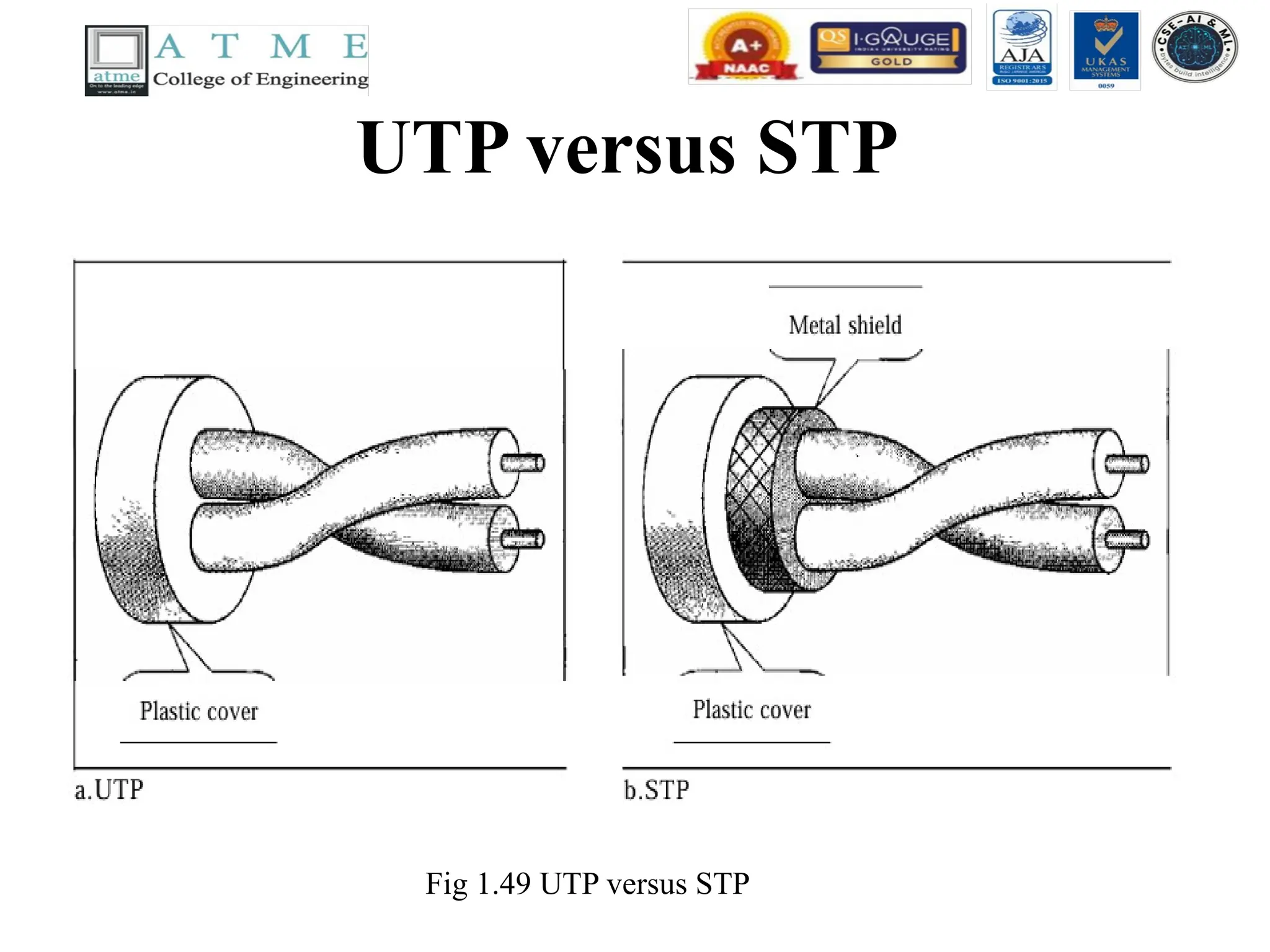
• UnshieldedVersus Shielded Twisted-Pair Cable
• The most common twisted-pair cable used in communications
is referred to as unshielded twisted-pair (UTP). IBM has also
produced a version of twisted-pair cable for its use called
shielded twisted-pair (STP).
• STP cable has a metal foil or braided mesh covering that
encases each pair of insulated conductors.
• Although metal casing improves the quality of cable by
preventing the penetration of noise or crosstalk, it is bulkier
and more expensive.
• Fig 1.49 shows the difference between UTP and STP.
Twisted-Pair Cable
contd..
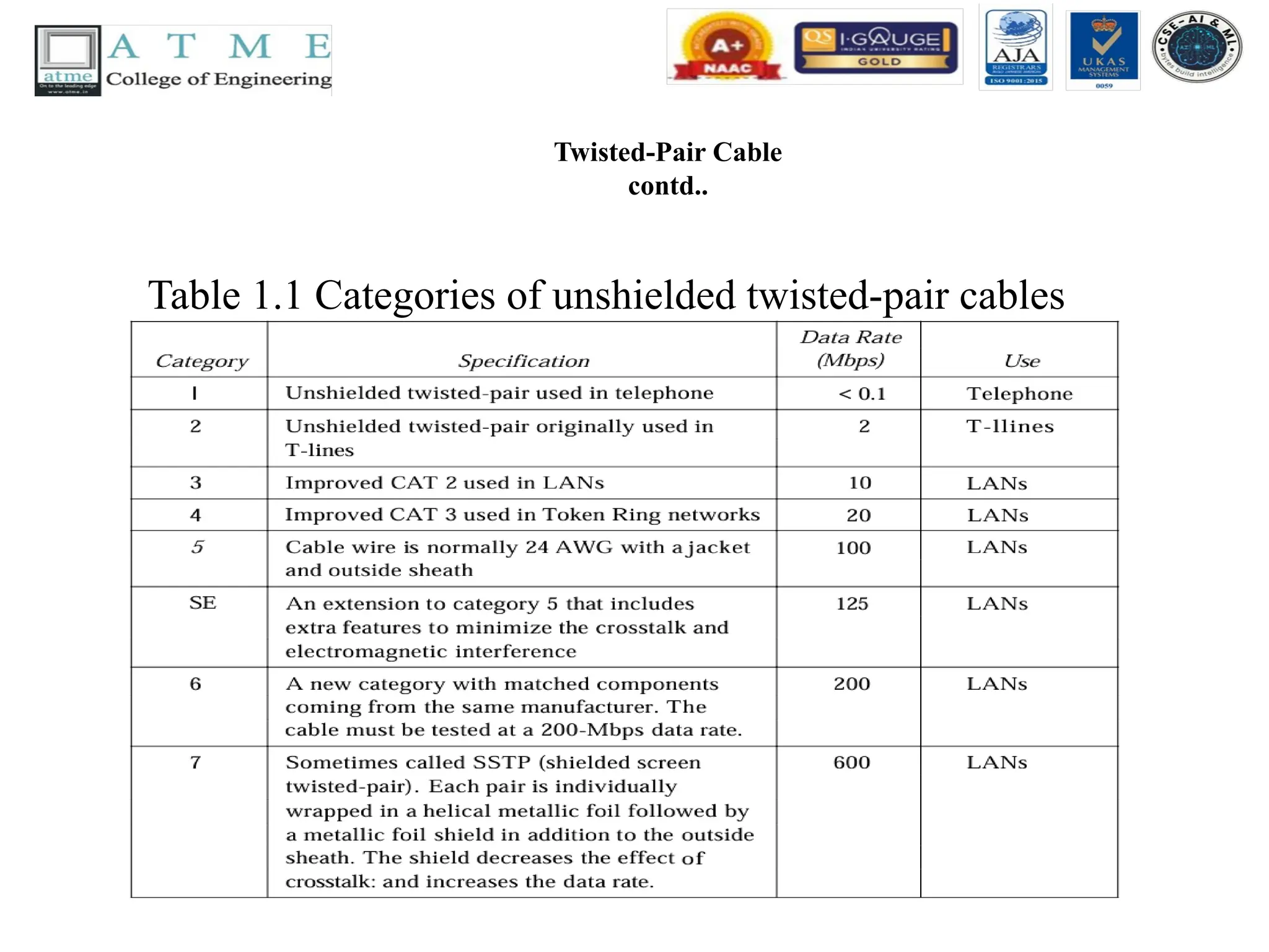
• Categories
•The Electronic Industries Association (EIA)
has developed standards to classify unshielded
twisted-pair cable into seven categories.
Categories are determined by cable quality,
with 1 as the lowest and 7 as the highest.
• Each EIA category is suitable for specific uses.
Table 1.1 shows these categories.
Twisted-Pair Cable
contd..
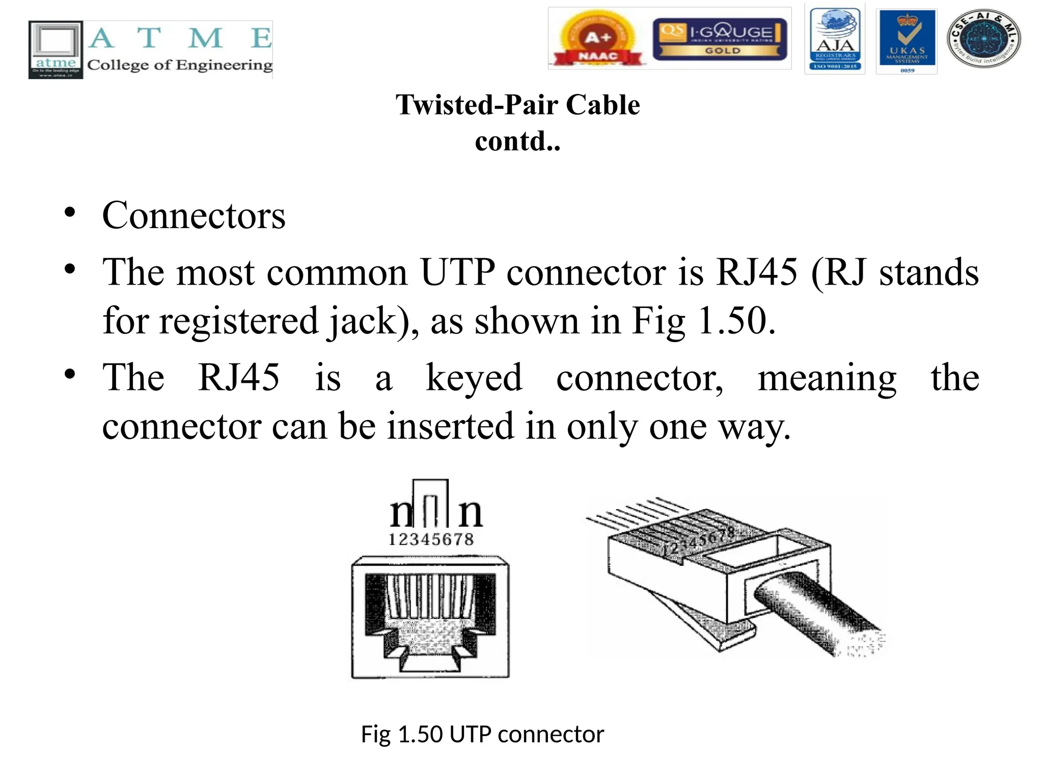
• Connectors
•The most common UTP connector is RJ45 (RJ stands
for registered jack), as shown in Fig 1.50.
• The RJ45 is a keyed connector, meaning the
connector can be inserted in only one way.
Fig 1.50 UTP connector
124.
Twisted-Pair Cable
contd..
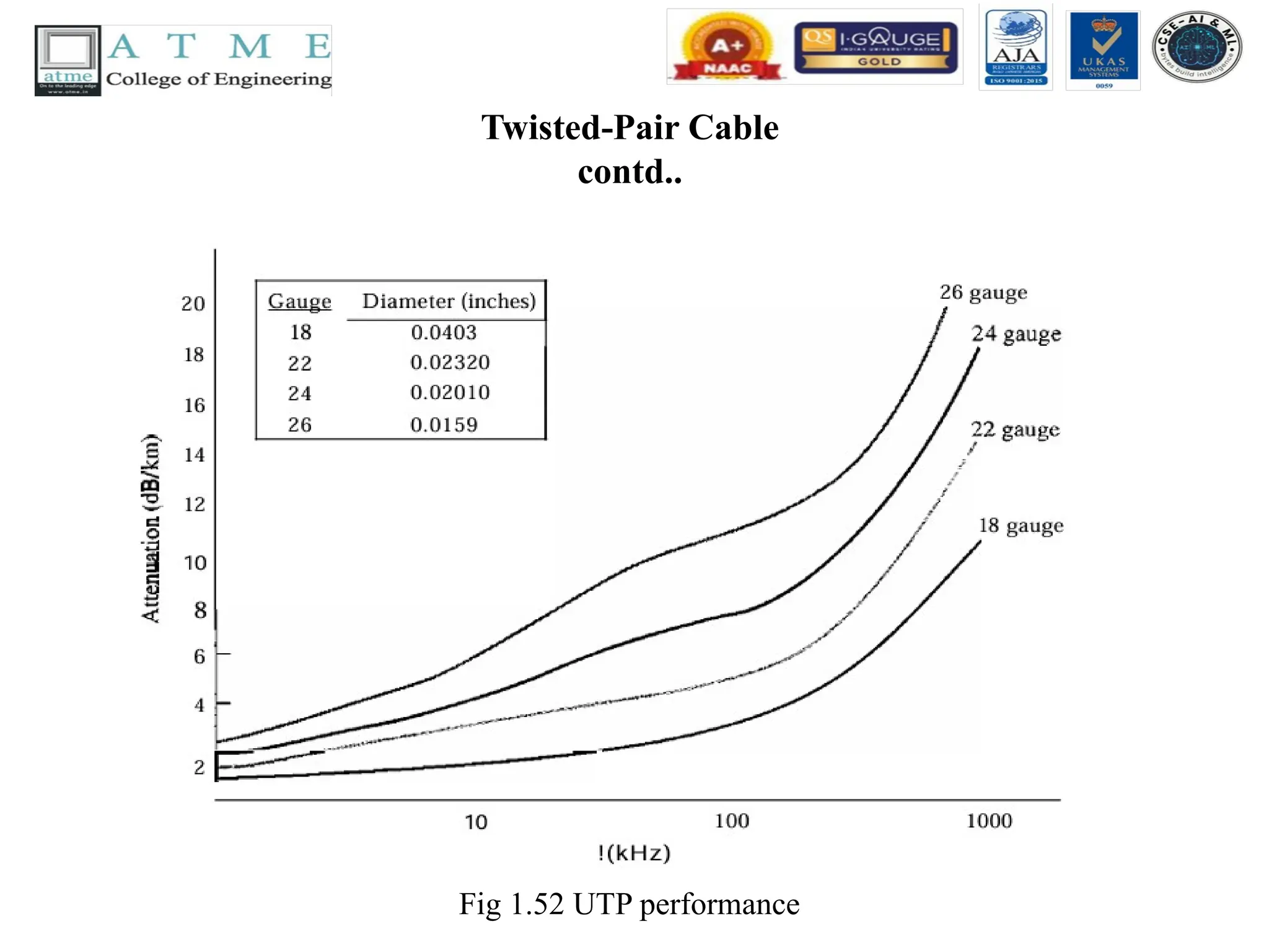
• Performance
•One way to measure the performance of twisted-pair cable
is to compare attenuation versus frequency and distance.
• A twisted-pair cable can pass a wide range of frequencies.
• However, Fig 1.52 shows that with increasing frequency,
the attenuation measured in decibels per kilometer
(dB/km), sharply increases with frequencies above
100kHz.
• Note that gauge is a measure of the thickness of the wire.
Applications of twistedpair cables
• Twisted-pair cables are used in telephone lines to provide
voice and data channels. The local loop-the line that connects
subscribers to the central telephone office---commonly
consists of unshielded twisted-pair cables.
• The DSL lines that are used by the telephone companies to
provide high-data-rate connections also use the high-
bandwidth capability of unshielded twisted-pair cables.
• Local-area networks, such as lOBase-T and lOOBase-T, also
use twisted-pair cables.
127.
Coaxial Cable
• Coaxialcable (or coax) carries signals of higher frequency
ranges than those in twisted pair cable, in part because the two
media are constructed quite differently.
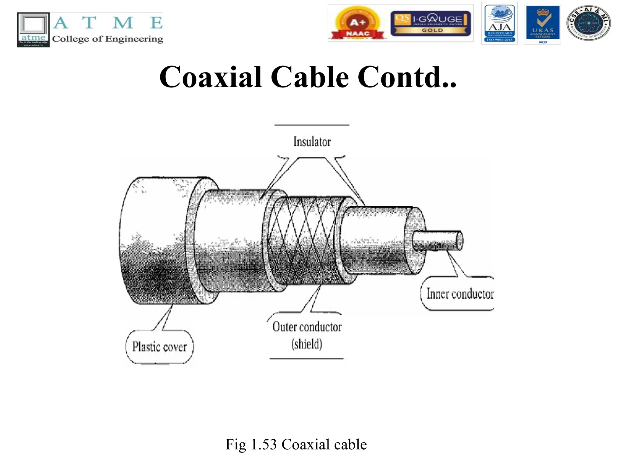
• Instead of having two wires, coax has a central core conductor of
solid or stranded wire (usually copper) enclosed in an insulating
sheath, which is, in turn, encased in an outer conductor of metal
foil, braid, or a combination of the two.
• The outer metallic wrapping serves both as a shield against noise
and as the second conductor, which completes the circuit. This
outer conductor is also enclosed in an insulating sheath, and the
whole cable is protected by a plastic cover (see Fig 1.53).
Coaxial Cable Contd..
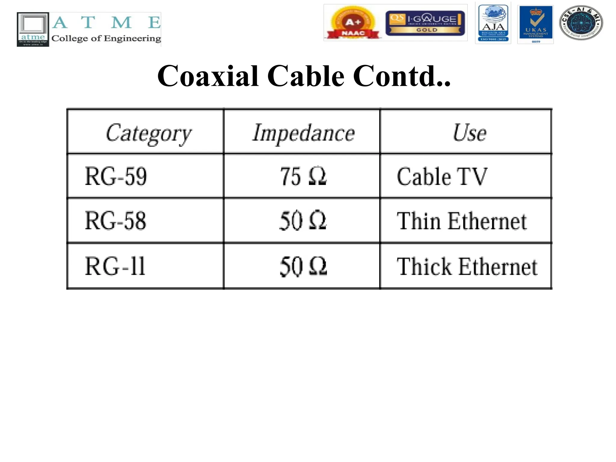
•Coaxial Cable Standards
• Coaxial cables are categorized by their radio
government (RG) ratings. Each RG number denotes
a unique set of physical specifications, including the
wire gauge of the inner conductor, the thickness and
type of the inner insulator, the construction of the
shield, and the size and type of the outer casing.
Each cable defined by an RG rating is adapted for a
specialized function, as shown in Table 1.2.
Coaxial Cable Contd..
•Coaxial Cable Connectors
• To connect coaxial cable to devices, we need coaxial
connectors. The most common type of connector used today
is the Bayone-Neill-Concelman (BNe), connector. Fig 1.54
shows three popular types of these connectors: the BNC
connector, the BNCT connector, and the BNC terminator.
The BNC connector is used to connect the end of the cable
to a device, such as a TV set. The BNC T connector is used
in Ethernet networks to branch out to a connection to a
computer or other device. The BNC terminator is used at the
end of the cable to prevent the reflection of the signal.
132.
Coaxial Cable Contd..
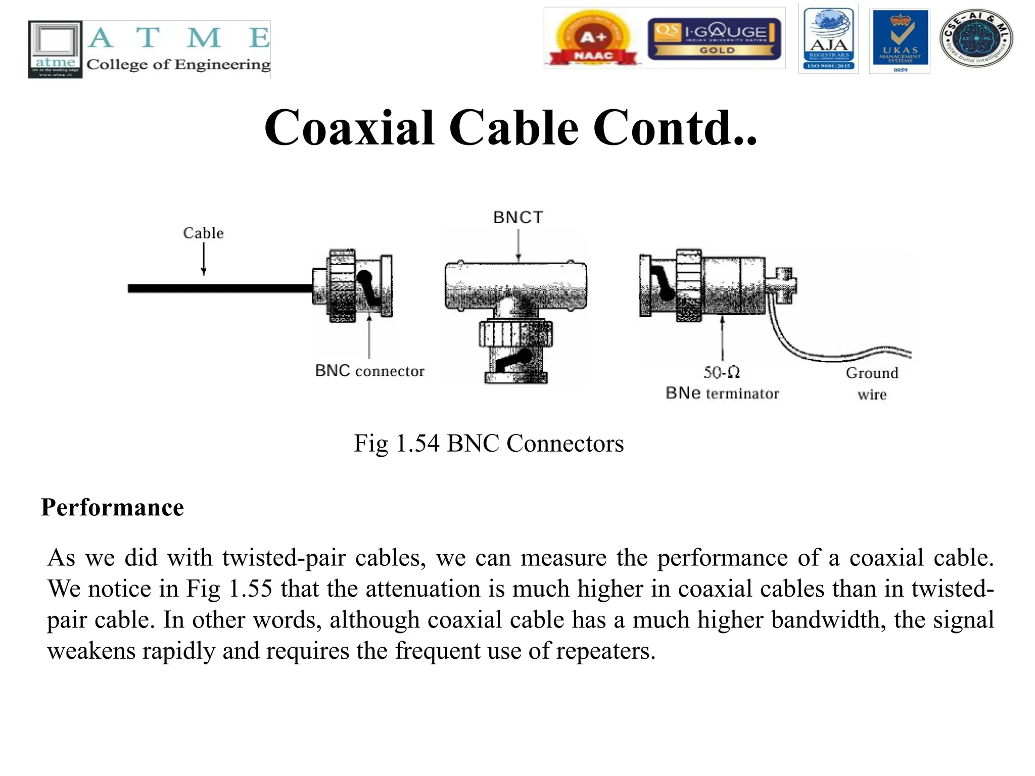
Fig1.54 BNC Connectors
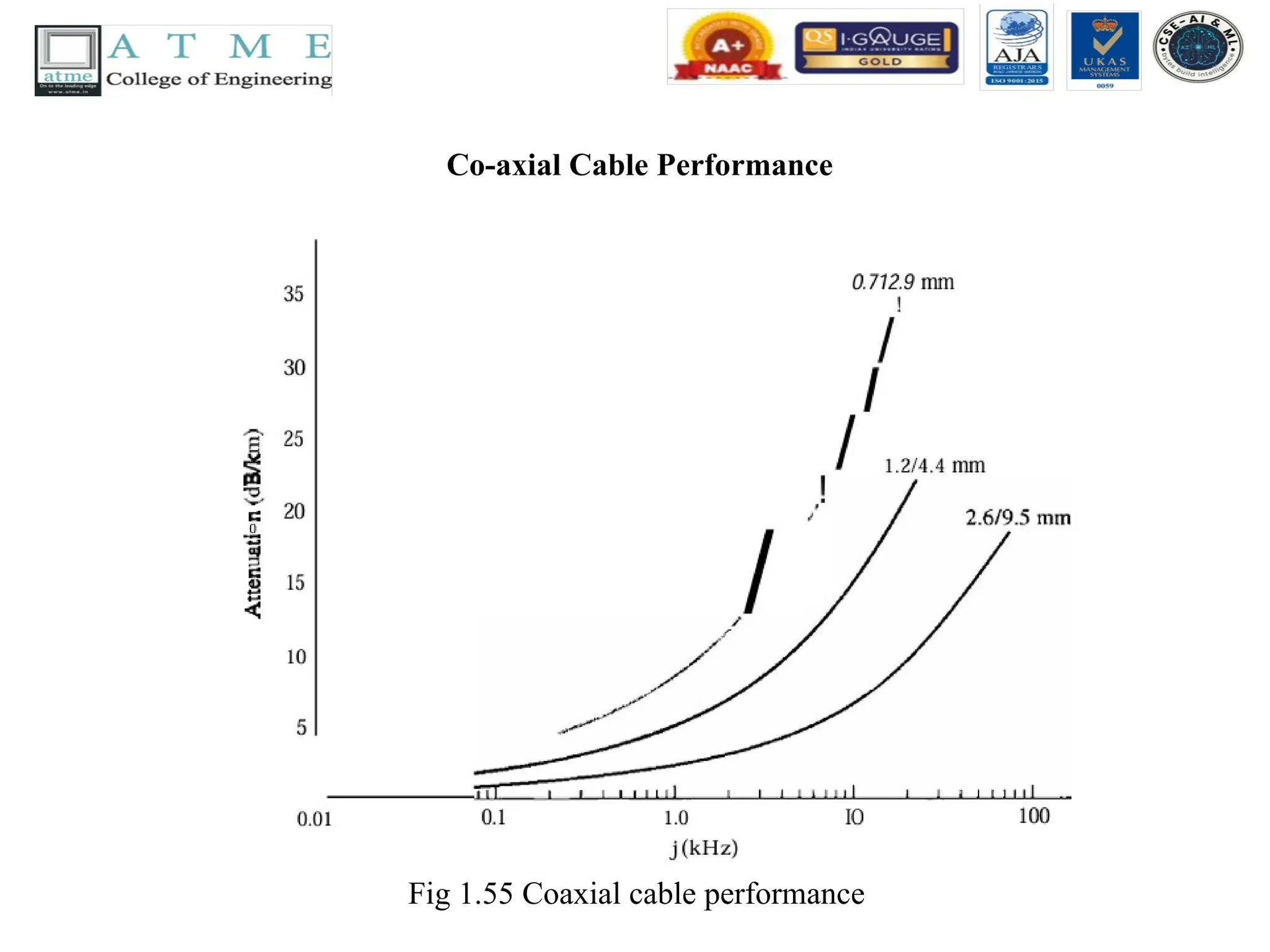
Performance
As we did with twisted-pair cables, we can measure the performance of a coaxial cable.
We notice in Fig 1.55 that the attenuation is much higher in coaxial cables than in twisted-
pair cable. In other words, although coaxial cable has a much higher bandwidth, the signal
weakens rapidly and requires the frequent use of repeaters.
Applications of co-axialcable
• Coaxial cable was widely used in analog telephone networks where a single coaxial network
could carry 10,000 voice signals.
• Later it was used in digital telephone networks where a single coaxial cable could carry digital
data up to 600 Mbps.
• However, coaxial cable in telephone networks has largely been replaced today with fiber-optic
cable.
• Cable TV networks (see Chapter 9) also use coaxial cables. In the traditional cable TV network,
the entire network used is coaxial cable. Later, however, cable TV providers. replaced most of
the media with fiber-optic cable; hybrid networks use coaxial cable only at the network
boundaries, near the consumer premises. Cable TV uses RG-59 coaxial cable.
• Another common application of coaxial cable is in traditional Ethernet LANs . Because of its
high bandwidth, and consequently high data rate, coaxial cable was chosen for digital
transmission in early Ethernet LANs.
• The 10Base-2, or Thin Ethernet, uses RG-58 coaxial cable with BNe connectors to transmit data
at 10 Mbps with a range of 185 m.
• The lOBase5, or Thick Ethernet, uses RG-11 (thick coaxial cable) to transmit 10 Mbps with a
range of 5000 m. Thick Ethernet has specialized connectors.
135.
Fiber-Optic Cable
• Afiber-optic cable is made of glass or plastic and transmits
signals in the form of light.
• To understand optical fiber, we first need to explore several
aspects of the nature of light.
• Light travels in a straight line as long as it is moving
through a single uniform substance.
• If a ray of light traveling through one substance suddenly
enters another substance (of a different density), the ray
changes direction. Fig 1.56 shows how a ray of light
changes direction when going from a more dense to a less
dense substance.
136.
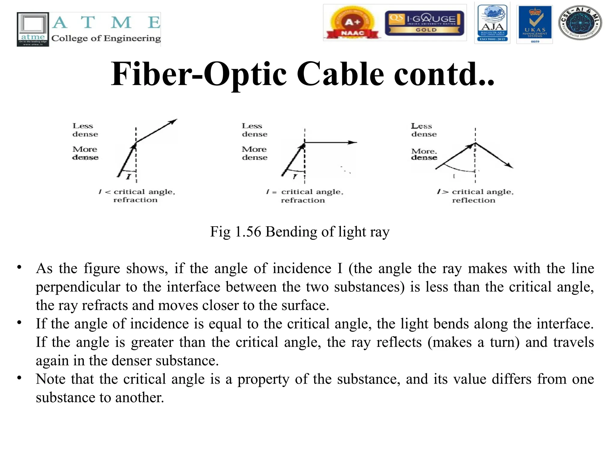
Fiber-Optic Cable contd..
Fig1.56 Bending of light ray
• As the figure shows, if the angle of incidence I (the angle the ray makes with the line
perpendicular to the interface between the two substances) is less than the critical angle,
the ray refracts and moves closer to the surface.
• If the angle of incidence is equal to the critical angle, the light bends along the interface.
If the angle is greater than the critical angle, the ray reflects (makes a turn) and travels
again in the denser substance.
• Note that the critical angle is a property of the substance, and its value differs from one
substance to another.
137.
Fiber-Optic Cable contd..
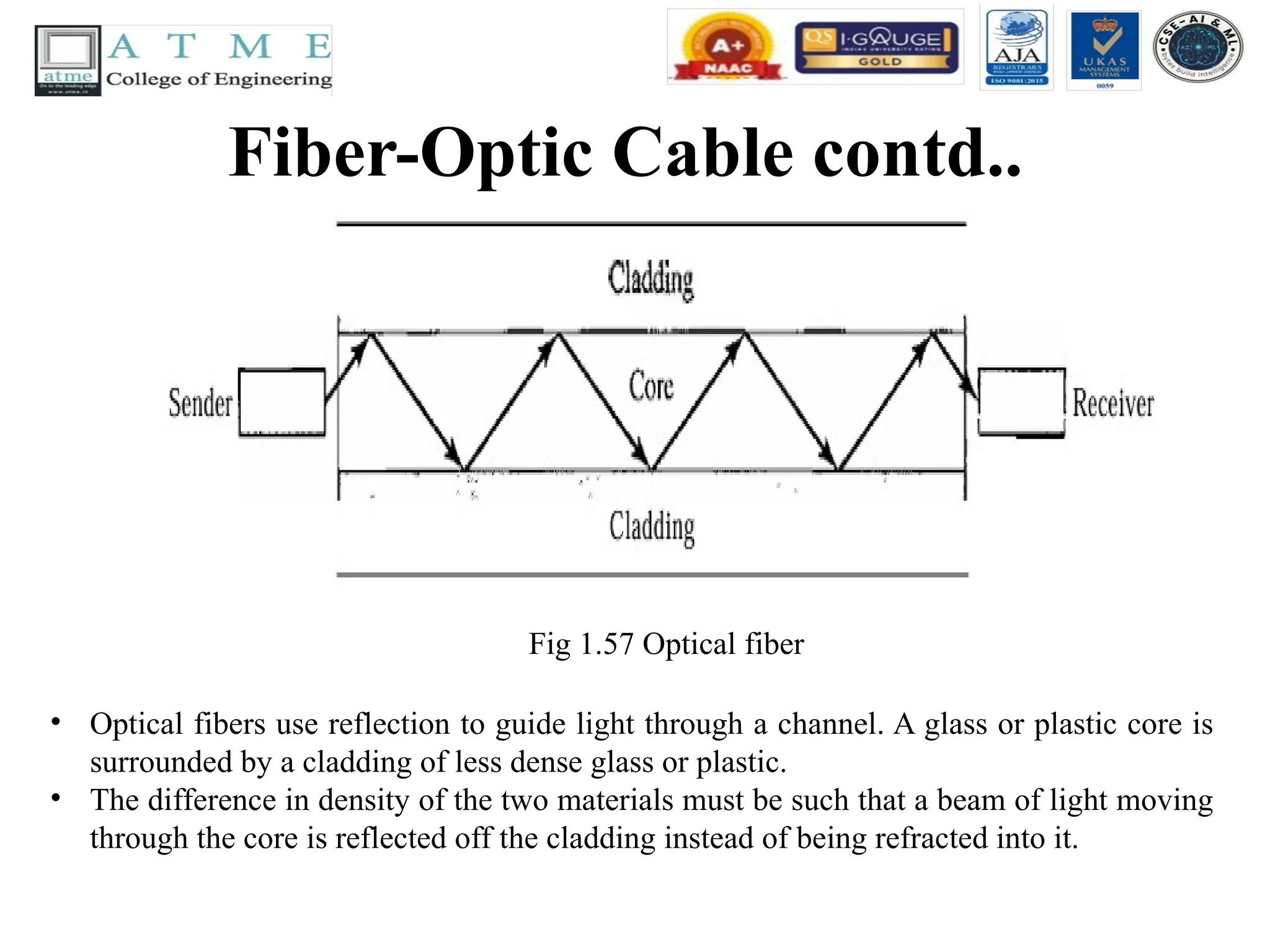
Fig1.57 Optical fiber
• Optical fibers use reflection to guide light through a channel. A glass or plastic core is
surrounded by a cladding of less dense glass or plastic.
• The difference in density of the two materials must be such that a beam of light moving
through the core is reflected off the cladding instead of being refracted into it.
138.
Fiber-Optic Cable contd..
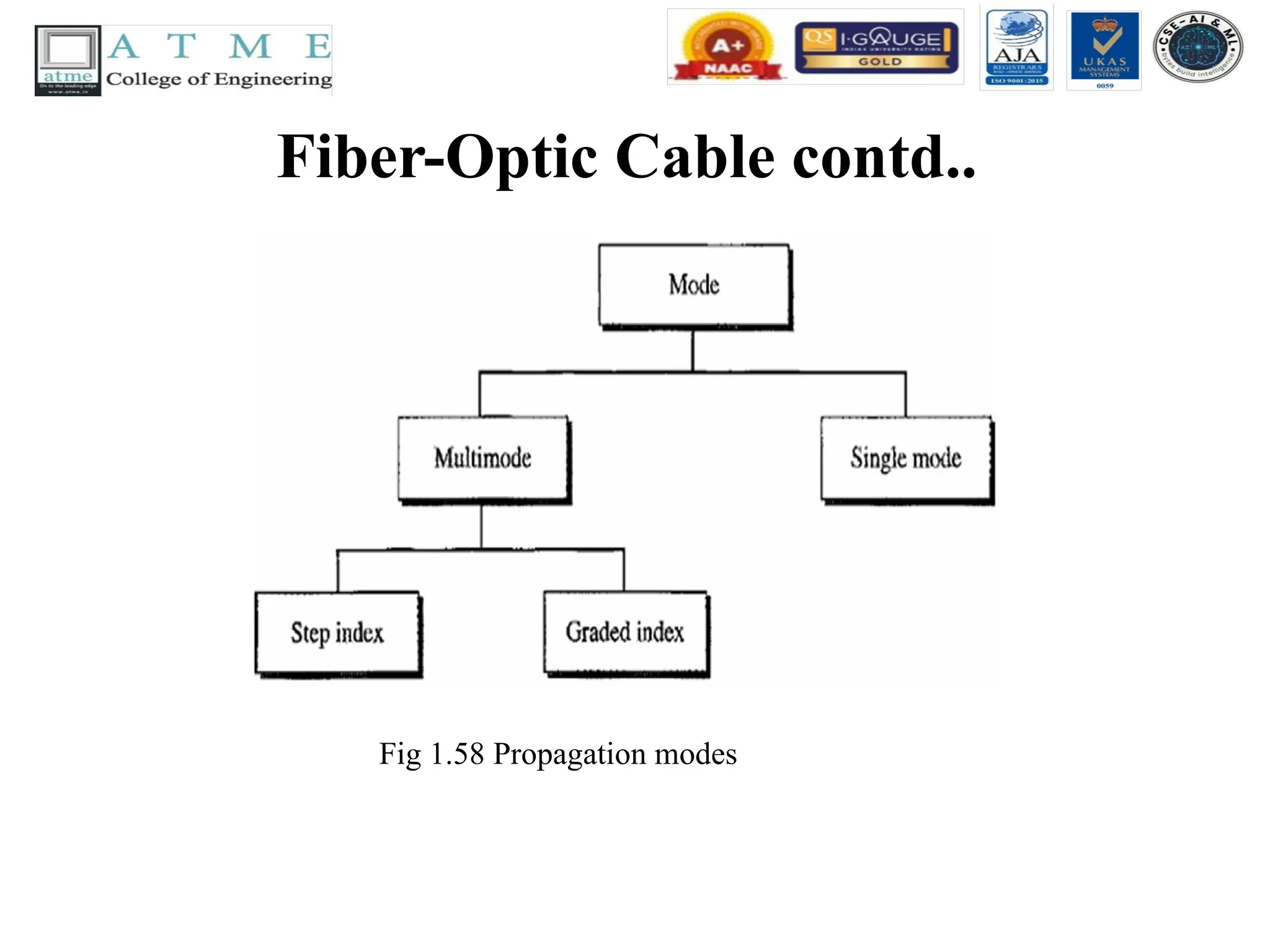
•Propagation Modes
• Current technology supports two modes
(multimode and single mode) for propagating
light along optical channels, each requiring
fiber with different physical characteristics.
Multi mode can be implemented in two forms:
step-index or graded-index.
Fiber-Optic Cable contd..
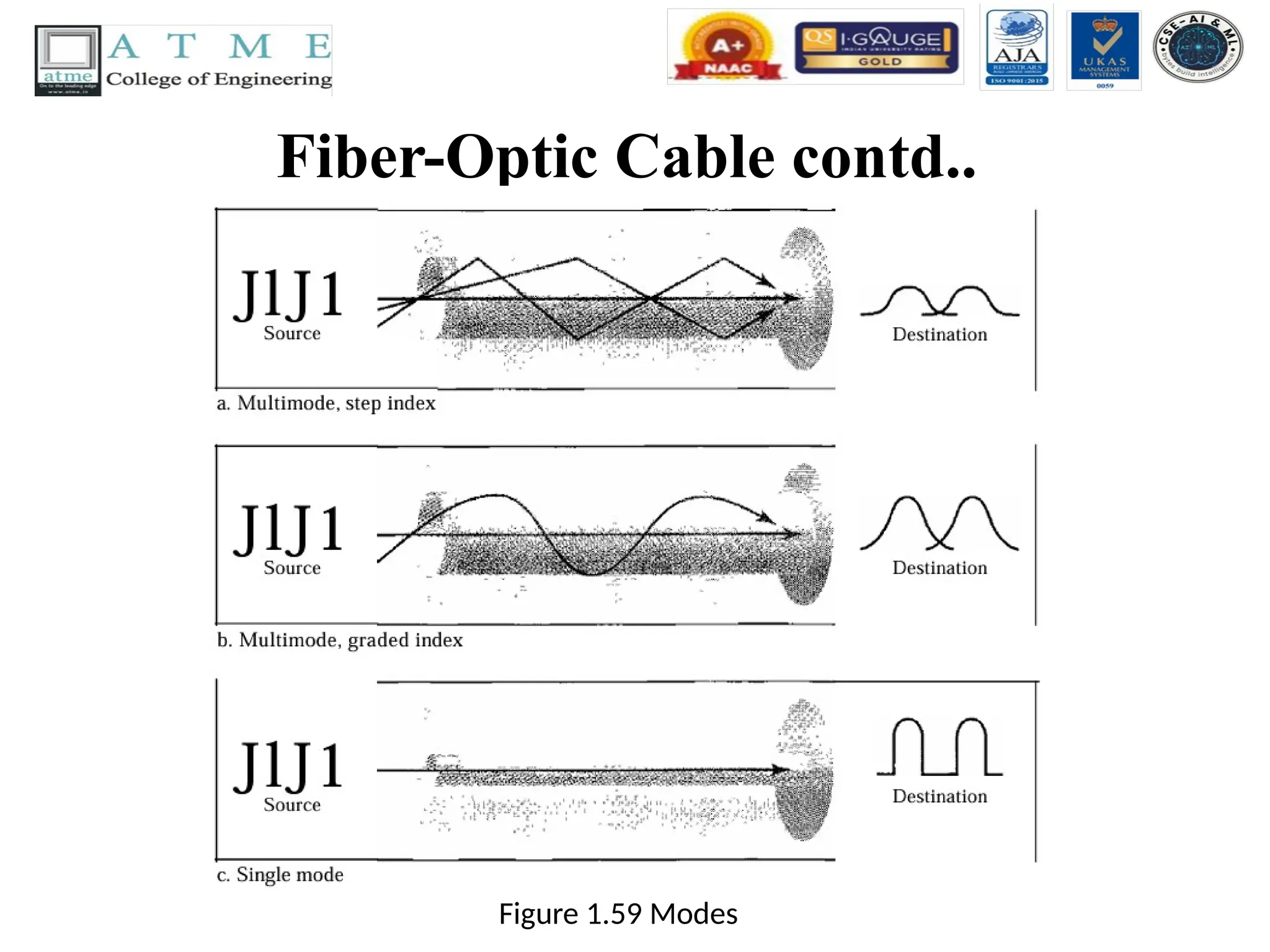
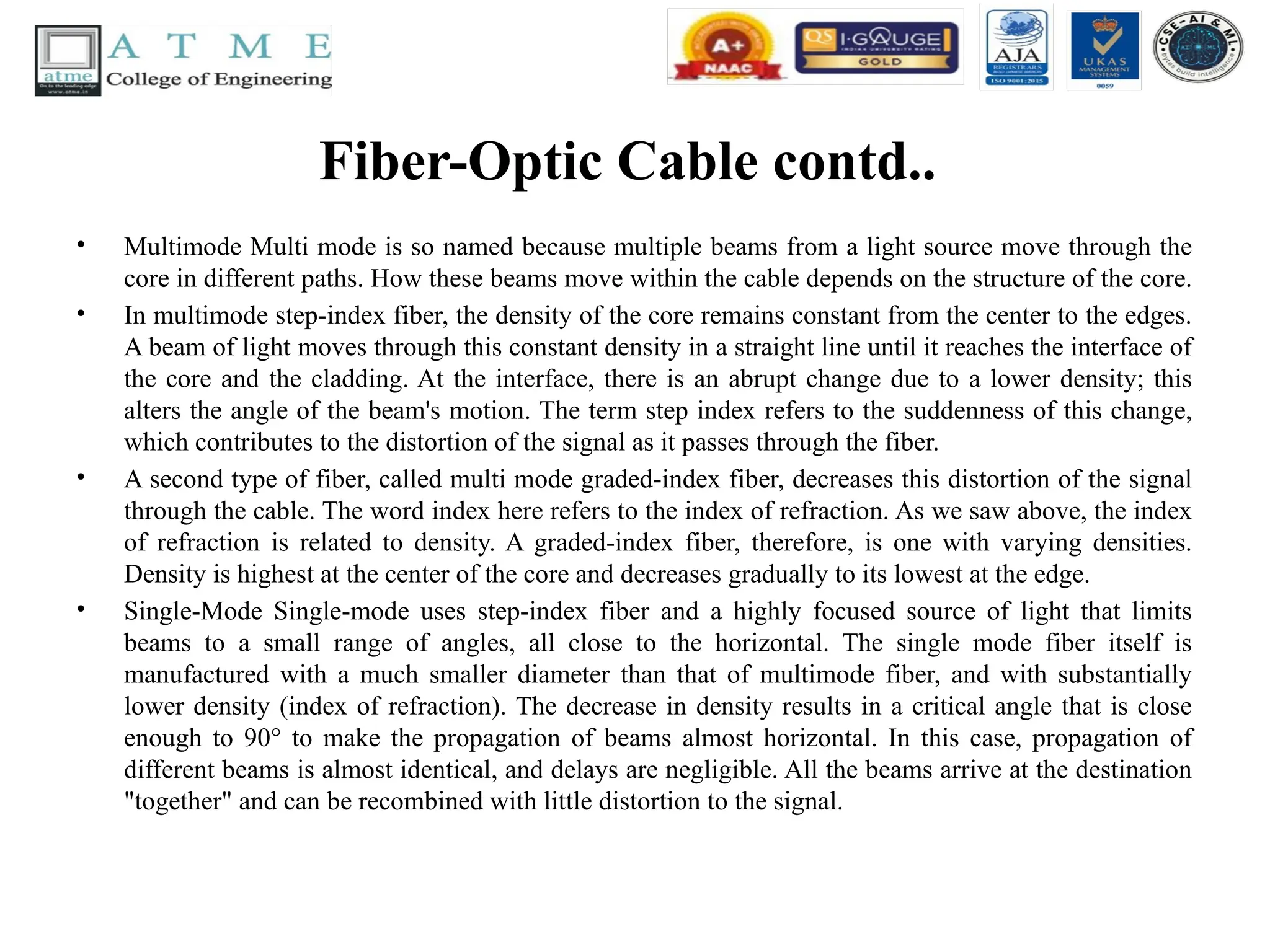
•Multimode Multi mode is so named because multiple beams from a light source move through the
core in different paths. How these beams move within the cable depends on the structure of the core.
• In multimode step-index fiber, the density of the core remains constant from the center to the edges.
A beam of light moves through this constant density in a straight line until it reaches the interface of
the core and the cladding. At the interface, there is an abrupt change due to a lower density; this
alters the angle of the beam's motion. The term step index refers to the suddenness of this change,
which contributes to the distortion of the signal as it passes through the fiber.
• A second type of fiber, called multi mode graded-index fiber, decreases this distortion of the signal
through the cable. The word index here refers to the index of refraction. As we saw above, the index
of refraction is related to density. A graded-index fiber, therefore, is one with varying densities.
Density is highest at the center of the core and decreases gradually to its lowest at the edge.
• Single-Mode Single-mode uses step-index fiber and a highly focused source of light that limits
beams to a small range of angles, all close to the horizontal. The single mode fiber itself is
manufactured with a much smaller diameter than that of multimode fiber, and with substantially
lower density (index of refraction). The decrease in density results in a critical angle that is close
enough to 90° to make the propagation of beams almost horizontal. In this case, propagation of
different beams is almost identical, and delays are negligible. All the beams arrive at the destination
"together" and can be recombined with little distortion to the signal.
142.
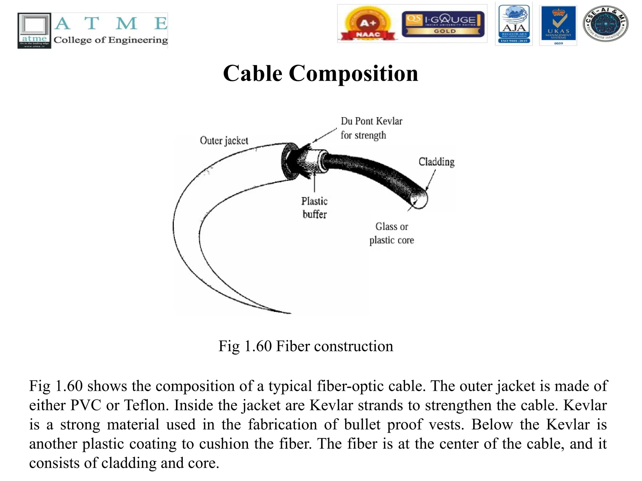
Cable Composition
Fig 1.60Fiber construction
Fig 1.60 shows the composition of a typical fiber-optic cable. The outer jacket is made of
either PVC or Teflon. Inside the jacket are Kevlar strands to strengthen the cable. Kevlar
is a strong material used in the fabrication of bullet proof vests. Below the Kevlar is
another plastic coating to cushion the fiber. The fiber is at the center of the cable, and it
consists of cladding and core.
143.
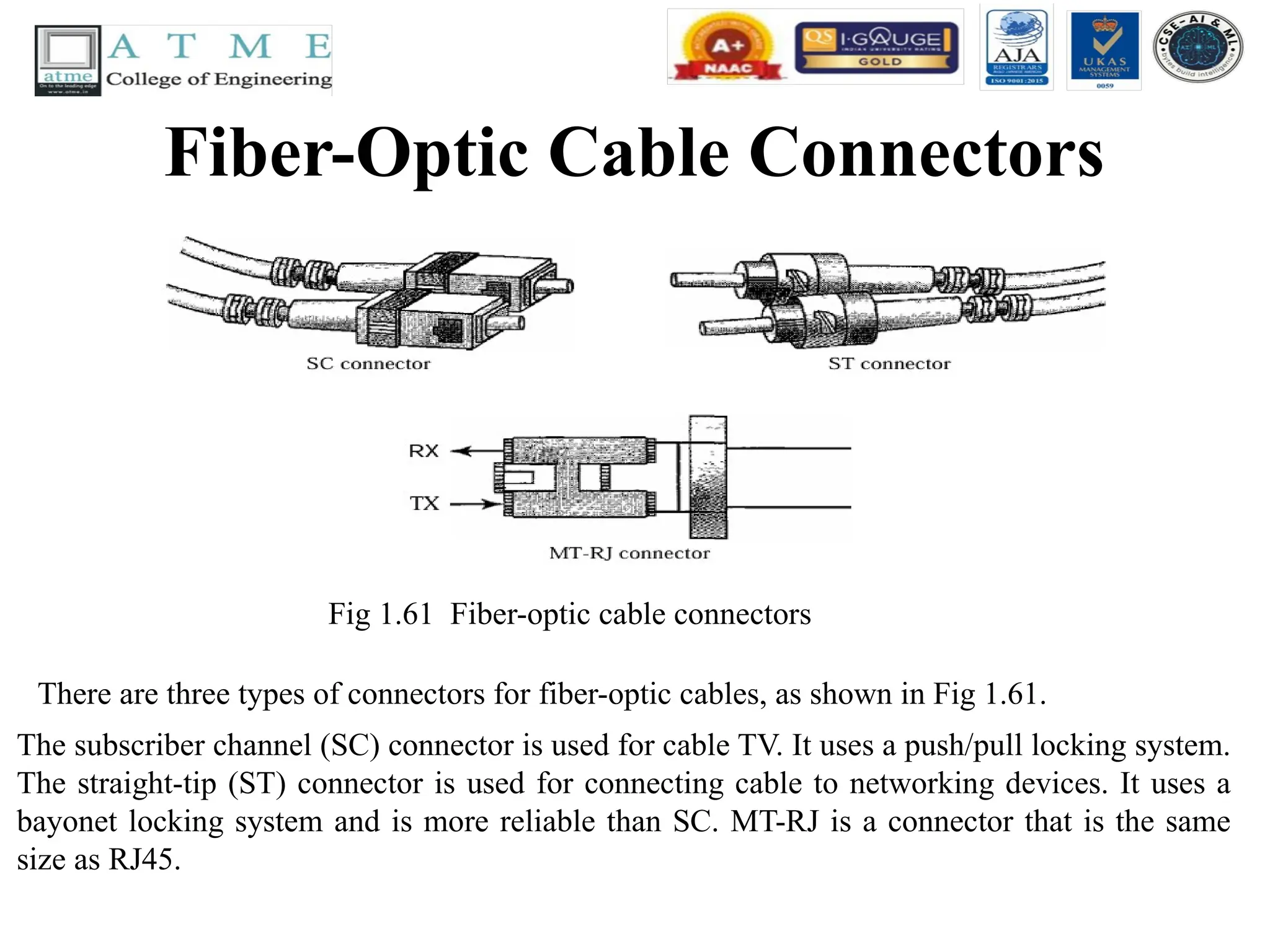
Fiber-Optic Cable Connectors
Fig1.61 Fiber-optic cable connectors
There are three types of connectors for fiber-optic cables, as shown in Fig 1.61.
The subscriber channel (SC) connector is used for cable TV. It uses a push/pull locking system.
The straight-tip (ST) connector is used for connecting cable to networking devices. It uses a
bayonet locking system and is more reliable than SC. MT-RJ is a connector that is the same
size as RJ45.
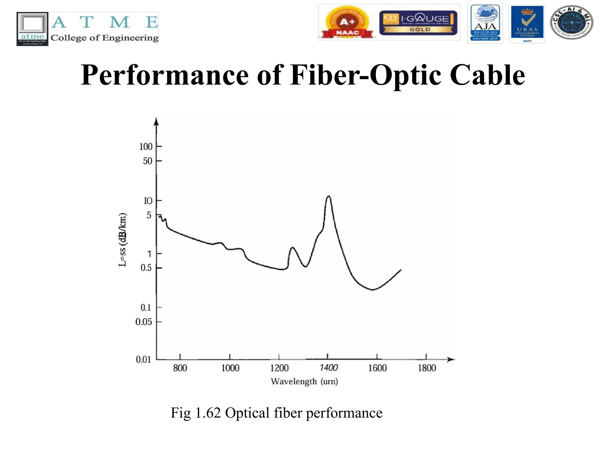
144.
Performance of FiberOptic Cable
• The plot of attenuation versus wavelength in
Fig 1.62 shows a very interesting phenomenon
in fiber-optic cable. Attenuation is flatter than
in the case of twisted-pair cable and coaxial
cable. The performance is such that we need
fewer (actually 10 times less) repeaters when
we use fiber-optic cable.
Applications of FiberOptic Cable
• Fiber-optic cable is often found in backbone networks
because its wide bandwidth is cost-effective.
• Some cable TV companies use a combination of optical
fiber and coaxial cable, thus creating a hybrid network.
Optical fiber provides the backbone structure while coaxial
cable provides the connection to the user premises.
• This is a cost-effective configuration since the narrow
bandwidth requirement at the user end does not justify the
use of optical fiber. Local-area networks such as 100Base-
FX network (Fast Ethernet) and 1000Base-X also use fiber-
optic cable.
147.
Advantages of OpticalFiber
• Fiber-optic cable has several advantages over metallic cable (twisted pair or
coaxial).
• Higher bandwidth. Fiber-optic cable can support dramatically higher bandwidths
(and hence data rates) than either twisted-pair or coaxial cable. Currently, data rates
and bandwidth utilization over fiber-optic cable are limited not by the medium but
by the signal generation and reception technology available.
• Less signal attenuation. Fiber-optic transmission distance is significantly greater
than that of other guided media. A signal can run for 50 km without requiring
regeneration. We need repeaters every 5 km for coaxial or twisted-pair cable.
• Immunity to electromagnetic interference. Electromagnetic noise cannot affect
fiber-optic cables.
• Resistance to corrosive materials. Glass is more resistant to corrosive materials
than copper.
• Lightweight. Fiber-optic cables are much lighter than copper cables.
• Greater immunity to tapping. Fiber-optic cables are more immune to tapping than
copper cables. Copper cables create antenna effects that can easily be tapped.
148.
Disadvantages of OpticalFiber
• There are some disadvantages in the use of optical fiber.
• Installation and maintenance. Fiber-optic cable is a relatively
new technology. Its installation and maintenance require
expertise that is not yet available everywhere.
• Unidirectional light propagation. Propagation of light is
unidirectional. If we need bidirectional communication, two
fibers are needed.
• Cost. The cable and the interfaces are relatively more
expensive than those of other guided media. If the demand
for bandwidth is not high, often the use of optical fiber
cannot be justified.
149.
UNGUIDED MEDIA: WIRELESS
•Unguided media transport electromagnetic
waves without using a physical conductor.
This type of communication is often referred
to as wireless communication. Signals are
normally broadcast through free space and
thus are available to anyone who has a device
capable of receiving them.
150.
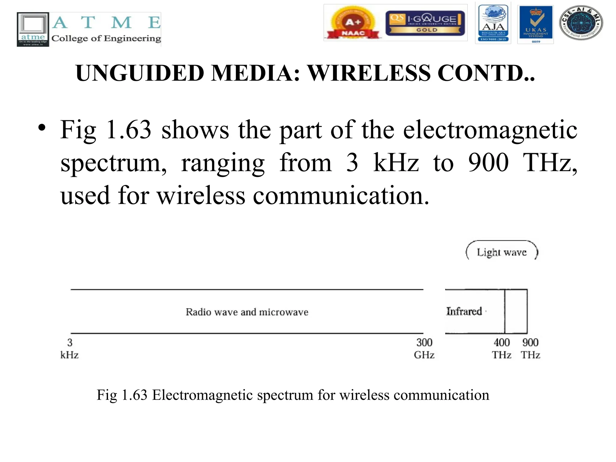
UNGUIDED MEDIA: WIRELESSCONTD..
• Fig 1.63 shows the part of the electromagnetic
spectrum, ranging from 3 kHz to 900 THz,
used for wireless communication.
Fig 1.63 Electromagnetic spectrum for wireless communication
151.
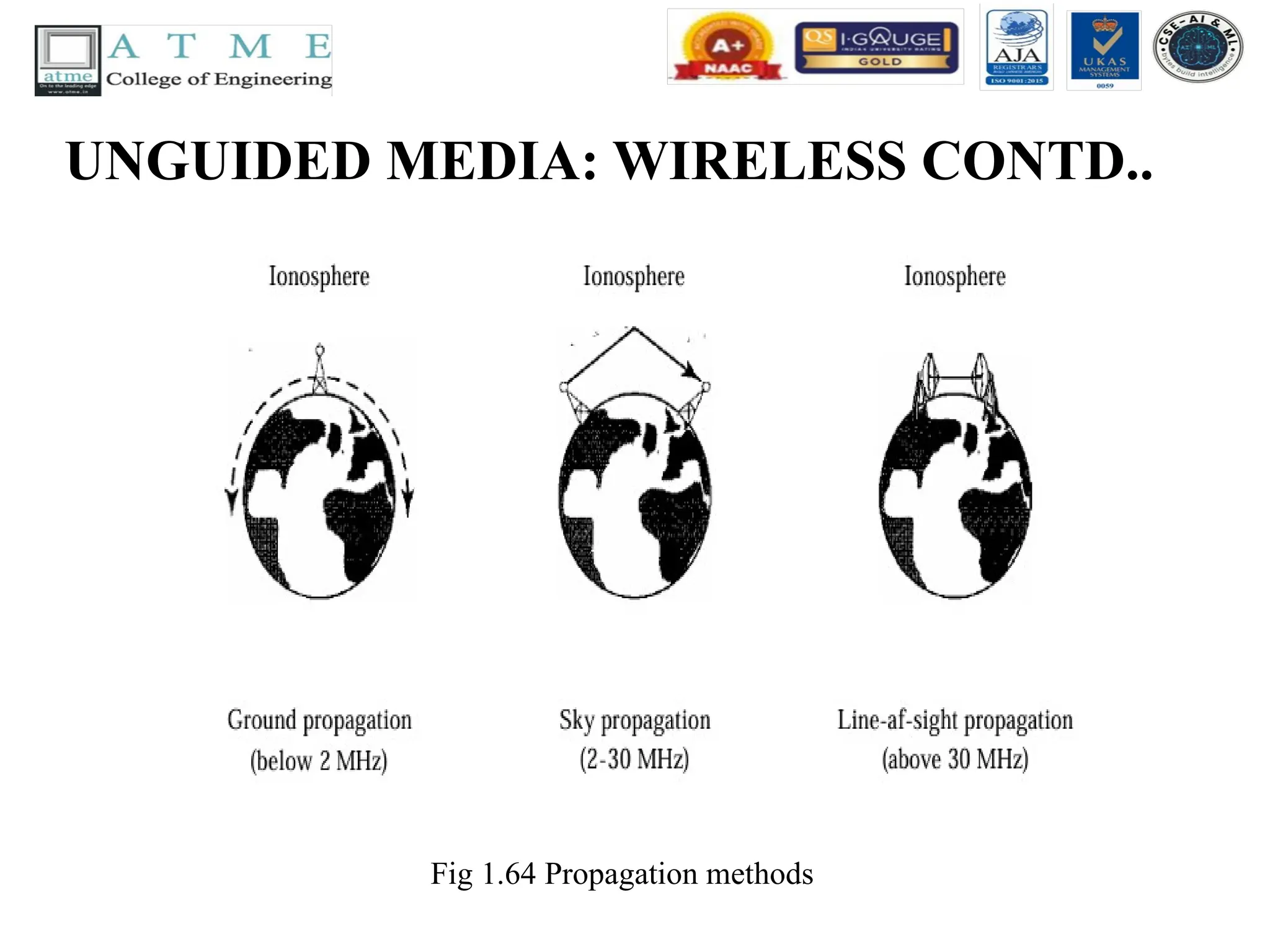
UNGUIDED MEDIA: WIRELESSCONTD..
• Unguided signals can travel from the source to destination in several ways: ground
propagation, sky propagation, and line-of-sight propagation, as shown in Fig 1.64.
• In ground propagation, radio waves travel through the lowest portion of the
atmosphere, hugging the earth. These low-frequency signals emanate in all directions
from the transmitting antenna and follow the curvature of the planet.
• Distance depends on the amount of power in the signal: The greater the power, the
greater the distance.
• In sky propagation, higher-frequency radio waves radiate upward into the ionosphere
(the layer of atmosphere where particles exist as ions) where they are reflected back to
earth. This type of transmission allows for greater distances with lower output power.
• In line-or-sight propagation, very high-frequency signals are transmitted in straight
lines directly from antenna to antenna. Antennas must be directional, facing each other,
and either tall enough or close enough together not to be affected by the curvature of
the earth. Line-of-sight propagation is tricky because radio transmissions cannot be
completely focused.
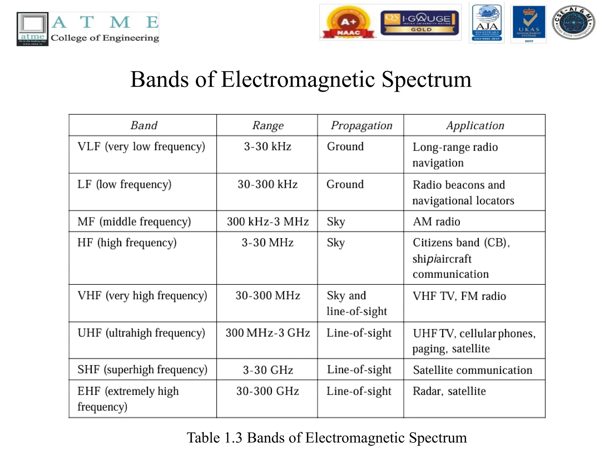
UNGUIDED MEDIA: WIRELESSCONTD..
• The section of the electromagnetic spectrum
defined as radio waves and microwaves is
divided into eight ranges, called bands, each
regulated by government authorities. These
bands are rated from very low frequency
(VLF) to extremely high frequency (EHF).
Table 1.3 lists these bands, their ranges,
propagation methods, and some applications.
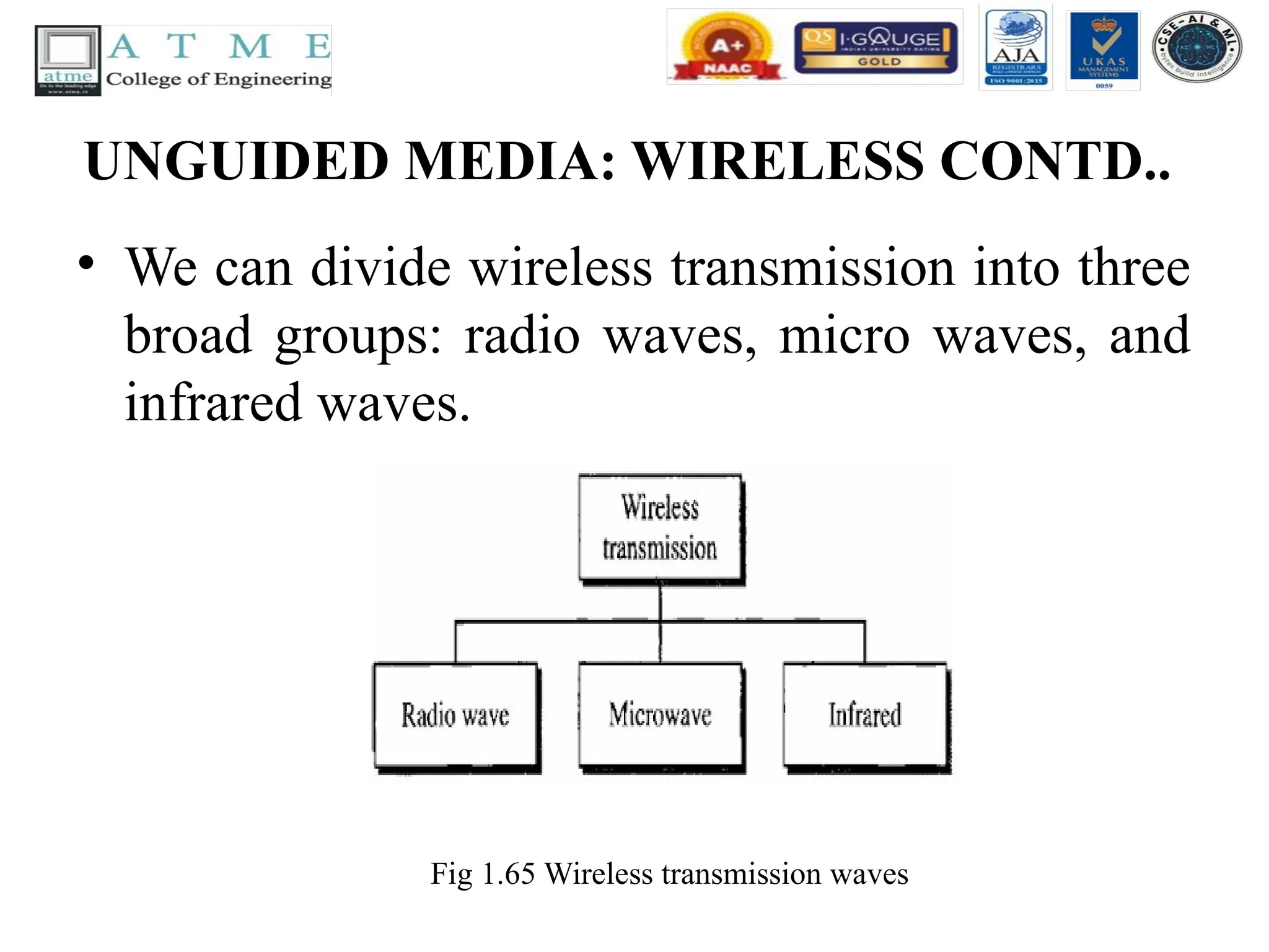
UNGUIDED MEDIA: WIRELESSCONTD..
• We can divide wireless transmission into three
broad groups: radio waves, micro waves, and
infrared waves.
Fig 1.65 Wireless transmission waves
156.
Radio Waves
• RadioWaves
• Although there is no clear-cut demarcation between radio waves and microwaves, electro magnetic waves
ranging in frequencies between 3 kHz and 1GHz are normally called radio waves;
• waves ranging in frequencies between 1 and 300 GHz are called micro waves. However, the behavior of the
waves, rather than the frequencies, is a better criterion for classification. Radio waves, for the most part, are
omnidirectional.
• When an antenna transmits radio waves, they are propagated in all directions. This means that the
sending and receiving antennas do not have to be aligned. A sending antenna sends waves that can be
received by any receiving antenna. The omnidirectional property has a disadvantage, too. The radio
waves transmitted by one antenna are susceptible to interference by another antenna that may send
signals using the same frequency or band.
• Radio waves, particularly those waves that propagate in the sky mode, can travel long distances. This
makes radio waves a good candidate for long-distance broadcasting such as AM radio. Radio waves,
particularly those of low and medium frequencies, can penetrate walls.
• This characteristic can be both an advantage and a disadvantage. It is an advantage because, for
example, an AM radio can receive signals inside a building. It is a disadvantage because we cannot
isolate a communication to just inside or outside a building. The radio wave band is relatively narrow,
just under 1 GHz, compared to the microwave band. When this band is divided into sub bands, the sub
bands are also narrow, leading to a low data rate for digital communications.
157.
Radio Waves Contd..
•Omnidirectional Antenna
• Radio waves use omnidirectional antennas that
send out signals in all directions. Based on the
wavelength, strength, and the purpose of
transmission, we can have several types of
antennas. Fig 1.65 shows an omnidirectional
antenna.
158.
Radio Waves Contd..
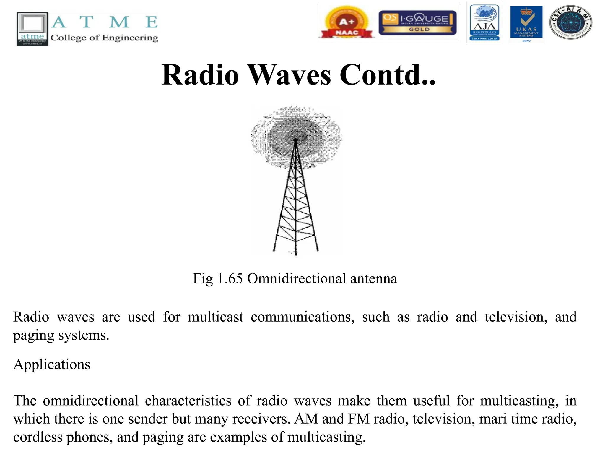
Fig1.65 Omnidirectional antenna
Radio waves are used for multicast communications, such as radio and television, and
paging systems.
Applications
The omnidirectional characteristics of radio waves make them useful for multicasting, in
which there is one sender but many receivers. AM and FM radio, television, mari time radio,
cordless phones, and paging are examples of multicasting.
159.
Microwaves
• Microwaves
• Electromagneticwaves having frequencies between 1 and 300 GHz are called micro waves.
Microwaves are unidirectional. When an antenna transmits micro waves, they can be narrowly
focused.
• This means that the sending and receiving antennas need to be aligned. The unidirectional
property has an obvious advantage.
• A pair of antennas can be aligned without interfering with another pair of aligned antennas.
The following describes some characteristics of microwave propagation:
• Microwave propagation is line-of-sight. Since the towers with the mounted antennas need to
be in direct sight of each other, towers that are far apart need to be very tall. The curvature of
the earth as well as other blocking obstacles do not allow two short towers to communicate by
using microwaves. Repeaters are often needed for long distance communication.
• Very high-frequency microwaves cannot penetrate walls. This characteristic can be a
disadvantage if receivers are inside buildings.
• The microwave band is relatively wide, almost 299 GHz. Therefore wider sub bands can be
assigned, and a high data rate is possible.
• Use of certain portions of the band requires permission from authorities.
160.
Microwaves Contd..
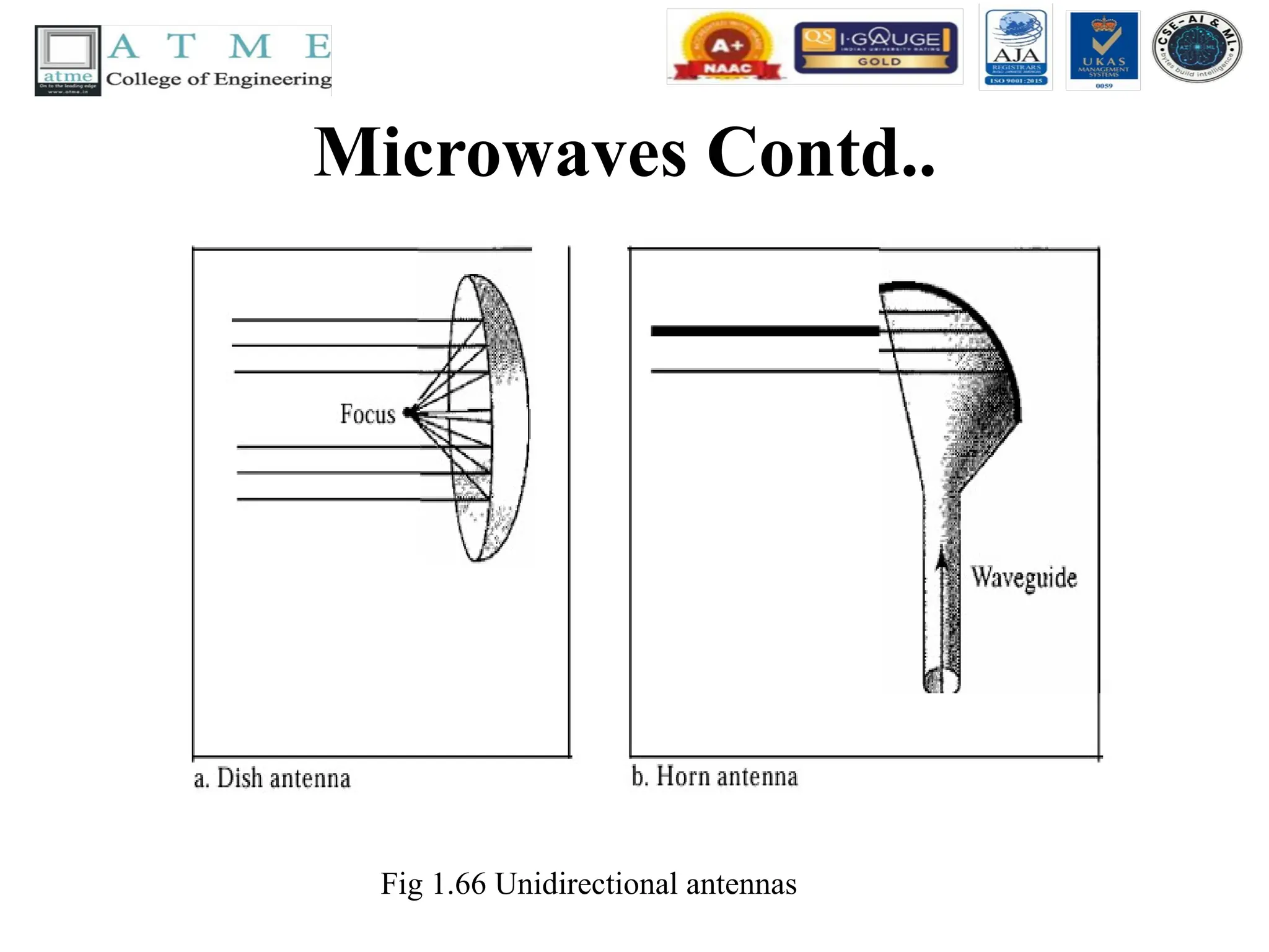
• UnidirectionalAntenna
• Microwaves need unidirectional antennas that send out signals in one direction.
Two types of antennas are used for microwave communications: the parabolic dish
and the horn (see Fig 1.66). A parabolic dish antenna is based on the geometry of a
parabola: Every line parallel to the line of symmetry (line of sight) reflects off the
curve at angles such that all the lines intersect in a common point called the focus.
• The parabolic dish works as a funnel, catching a wide range of waves and directing
them to a common point. In this way, more of the signal is recovered than would be
possible with a single-point receiver. Outgoing transmissions are broadcast through
a horn aimed at the dish. The micro waves hit the dish and are deflected outward in
a reversal of the receipt path. A horn antenna looks like a gigantic scoop. Outgoing
transmissions are broadcast up a stem (resembling a handle) and deflected outward
in a series of narrow parallel beams by the curved head. Received transmissions are
collected by the scooped shape of the horn, in a manner similar to the parabolic
dish, and are deflected down into the stem.
Microwaves Contd..
• Applications
•Microwaves, due to their unidirectional
properties, are very useful when unicast (one-to-
one) communication is needed between the
sender and the receiver. They are used in cellular
phones, satellite networks, and wireless LANs.
• Microwaves are used for unicast communication
such as cellular telephones, satellite networks,
and wireless LANs.
163.
Infrared waves
• Infrared
•Infrared waves, with frequencies from 300 GHz to 400 THz (wavelengths
from 1 mm to 770 nm), can be used for short-range communication.
• Infrared waves, having high frequencies, cannot penetrate walls. This
advantageous characteristic prevents interference between one system
and another; a short-range communication system in one room cannot be
affected by another system in the next room.
• When we use our infrared remote control, we do not interfere with the
use of the remote by our neighbors. However, this same characteristic
makes infrared signals useless for long-range communication. In
addition, we cannot use infrared waves outside a building because the
sun's rays contain infrared waves that can interfere with the
communication.
164.
Infrared waves Contd..
•Applications
• The infrared band, almost 400 THz, has an excellent potential for data
transmission. Such a wide bandwidth can be used to transmit digital data
with a very high data rate.
• The Infrared Data Association (IrDA), an association for sponsoring the
use of infrared waves, has established standards for using these signals for
communication between devices such as keyboards, mice, PCs, and
printers. For example, some manufacturers provide a special port called the
IrDA port that allows a wireless keyboard to communicate with a PC. The
standard originally defined a data rate of 75 kbps for a distance up to 8 m.
• The recent standard defines a data rate of 4 Mbps. Infrared signals defined
by IrDA transmit through line of sight; the IrDA port on the keyboard
needs to point to the PC for transmission to occur.