The document outlines the objectives and syllabus of a data communication course divided into five modules, covering topics such as digital data transmission, network types, medium access control, and LAN technologies. It discusses various communication protocols, network models, and the characteristics of data communication systems, including error detection, network topology, and performance metrics. The document also provides information on textbooks, course outcomes, and the internet's administrative structure.


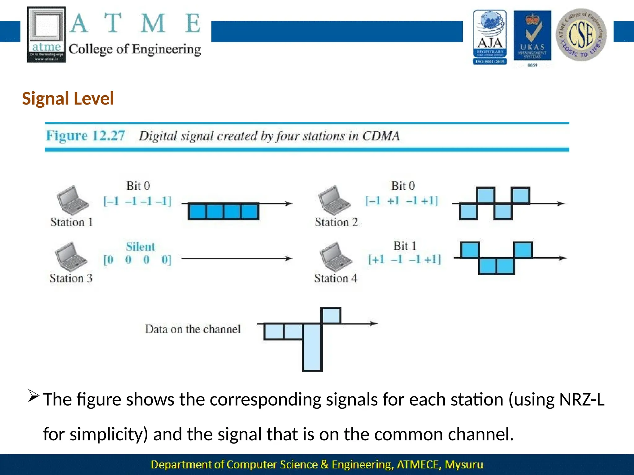
![ Now imagine that station 3, which we said is silent, is listening to station 2.
Station 3 multiplies the total data on the channel by the code for station
2, which is [+1 −1 +1 −1], to get](https://image.slidesharecdn.com/module-1-240915173347-7a8122ec/75/Module-1-pptx-Computer-Networks-BCS502-module-1-ppt-495-2048.jpg)