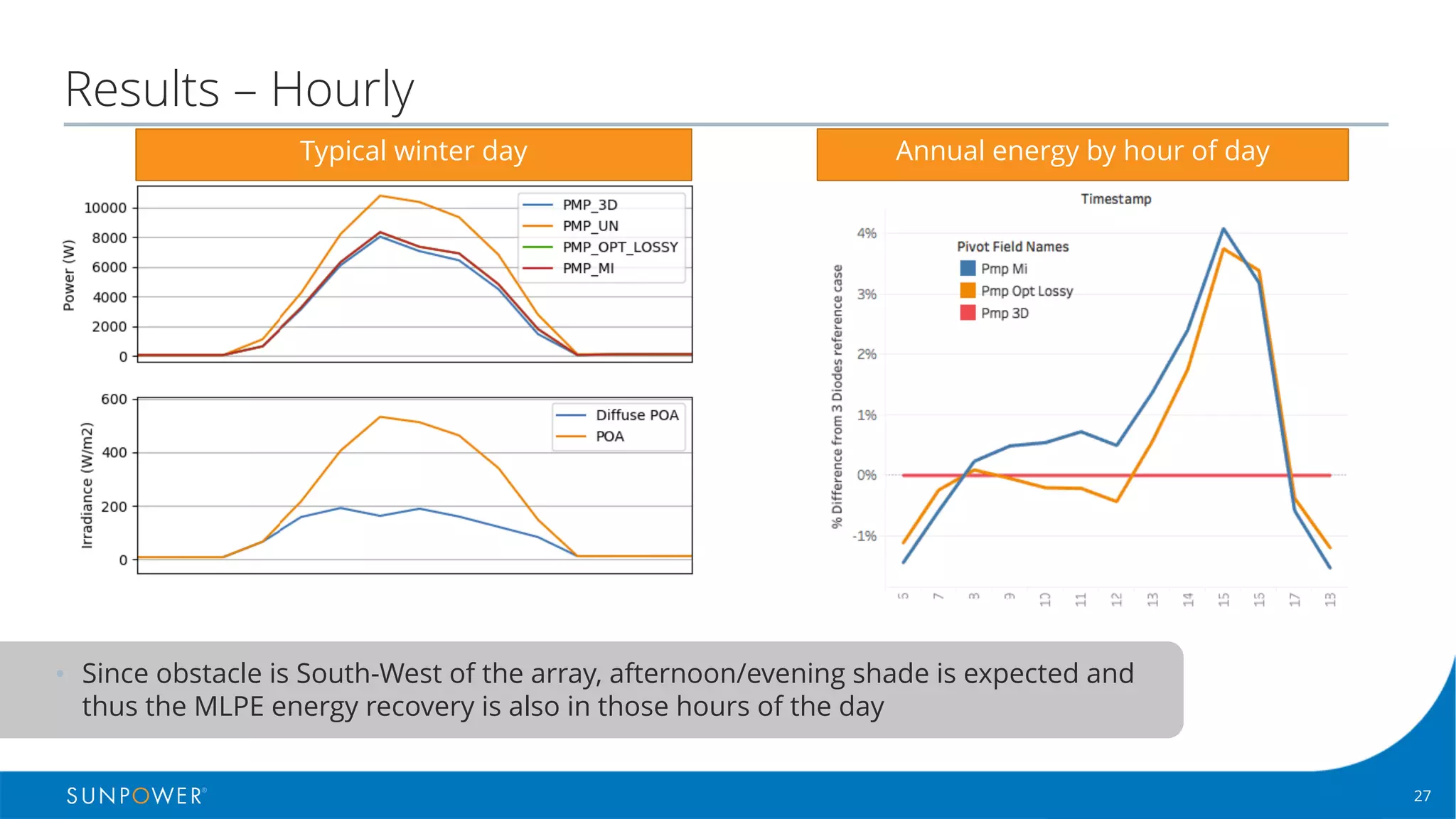
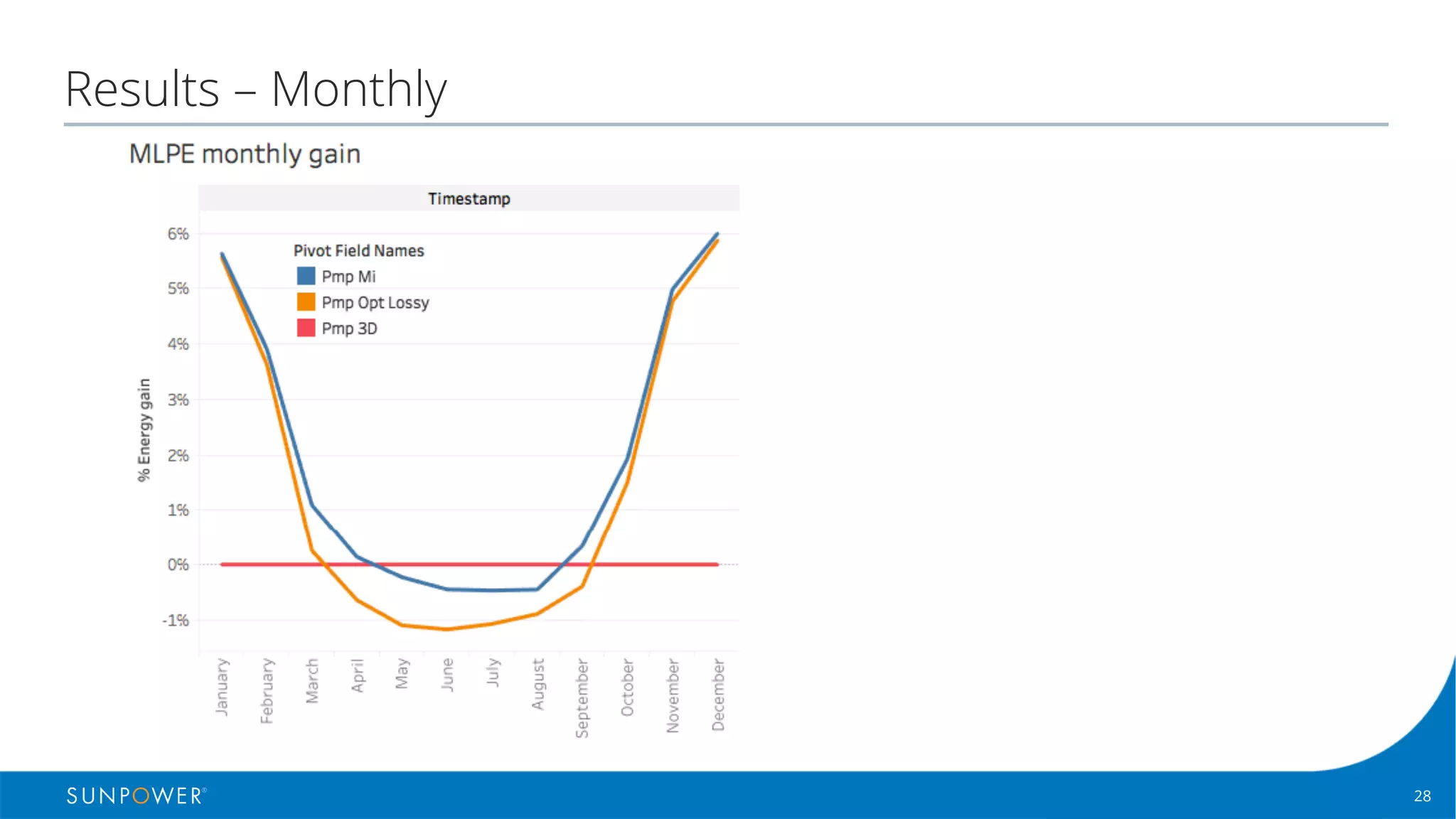
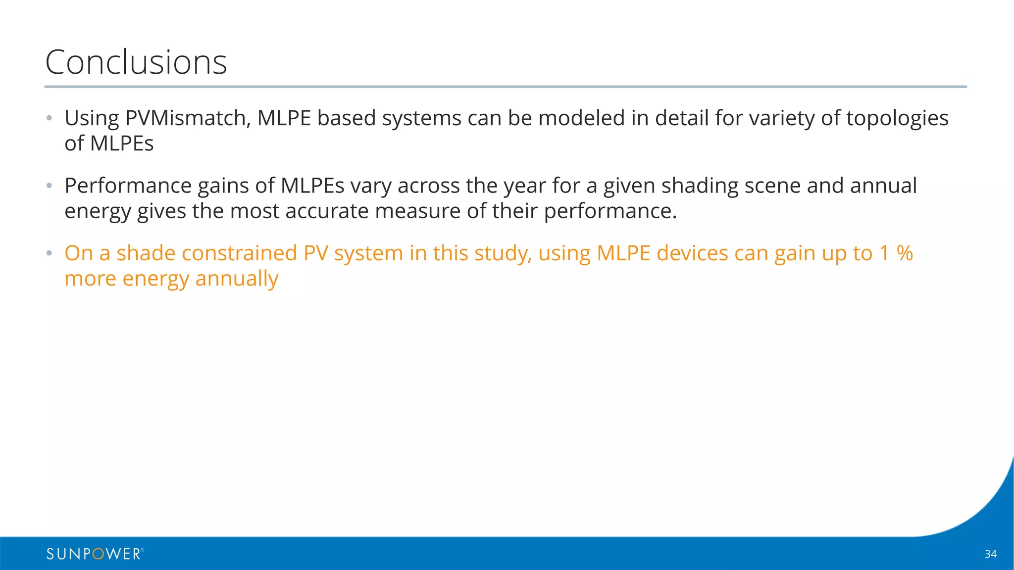
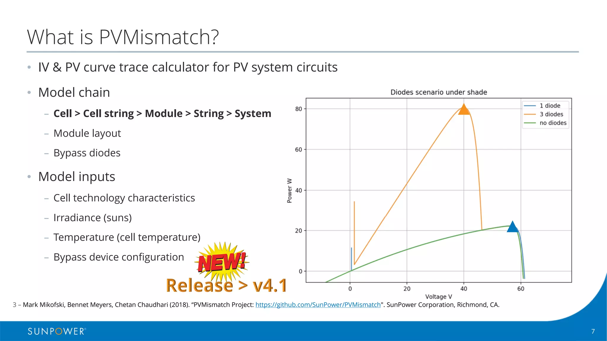
Module Level Power Electronics (MLPE) such as microinverters and power optimizers can increase the energy production of photovoltaic systems affected by shading. The PVMismatch software models different MLPE configurations and their impact on system performance over time. For a case study system in Richmond, CA with partial southwest shading, modeling showed MLPE technologies could recover up to 6% more energy in winter months and 1% more annually compared to an unoptimized string inverter system. PVMismatch allows detailed performance comparisons of MLPE solutions under different conditions.


![16Confidential | © 2016 SunPower Corporation |
Microinverters - method
1. Find MPP of each module for given irradiance
conditions
2. Find efficiency loss for that power level
3. Calculate Pmpmod[MI]
Pmp map (MI)
Available Incident
Energy](https://image.slidesharecdn.com/pvpmcmlpechetanchaudhari-track32pmslotv2-190520154349/75/MLPE-performance-modeling-16-2048.jpg)
![17Confidential | © 2016 SunPower Corporation |
Microinverters - method
1. Find MPP of each module for given irradiance
conditions
2. Find efficiency loss for that power level
3. Calculate Pmpmod[MI]
4. Sum the Pmpmod[MI] across the array to get Pmpsys
Pmp map (MI)
Available Incident
Energy](https://image.slidesharecdn.com/pvpmcmlpechetanchaudhari-track32pmslotv2-190520154349/75/MLPE-performance-modeling-17-2048.jpg)

![22Confidential | © 2016 SunPower Corporation |
DC optimizers - method
1
2
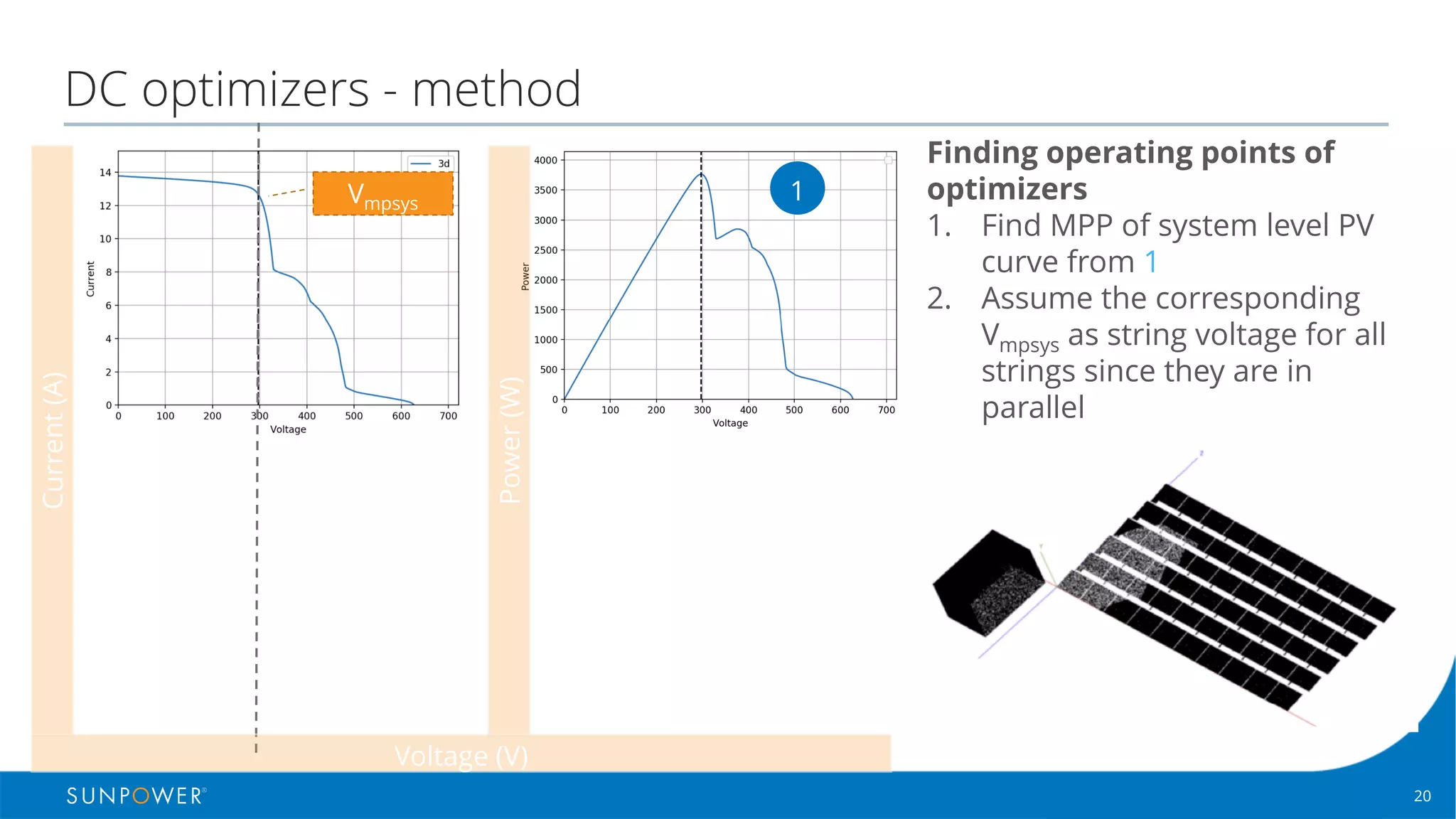
Finding operating points of
optimizers
1. Find MPP of system level PV
curve from 1
2. Assume the Vmpsys as string
voltage for all strings
3. Find Iout for each string by
locating Istring from 2 for Vmpsys
(dotted line)
4. Calculate duty cycle and
efficiency for each optimizer
and adjust module Pmpmod[OPT]
Current(A)
Power(W)
Voltage (V)](https://image.slidesharecdn.com/pvpmcmlpechetanchaudhari-track32pmslotv2-190520154349/75/MLPE-performance-modeling-22-2048.jpg)
![23Confidential | © 2016 SunPower Corporation |
DC optimizers - method
1
2
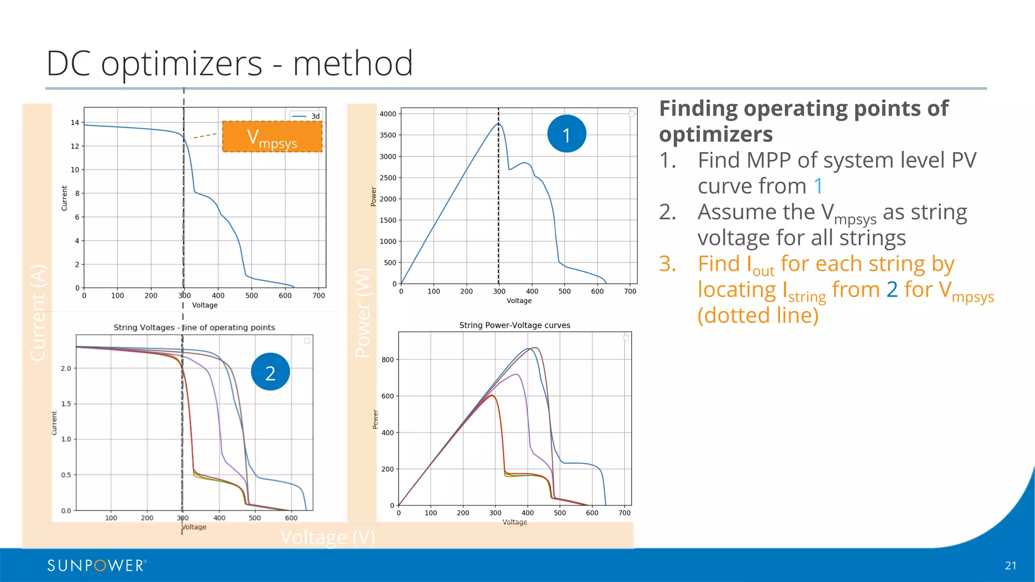
Finding operating points of
optimizers
1. Find MPP of system level PV
curve from 1
2. Assume the Vmpsys as string
voltage for all strings
3. Find Iout for each string by
locating Istring from 2 for Vmpsys
(dotted line)
4. Calculate duty cycle and
efficiency for each optimizer
and adjust module Pmpmod[OPT]
5. Sum the Pmpmod[OPT] to get
Pmpsys[OPT]
Current(A)
Power(W)
Voltage (V)](https://image.slidesharecdn.com/pvpmcmlpechetanchaudhari-track32pmslotv2-190520154349/75/MLPE-performance-modeling-23-2048.jpg)
![24Confidential | © 2016 SunPower Corporation |
DC optimizers - method
1
2
Finding operating points of
optimizers
1. Find MPP of system level PV
curve from 1
2. Assume the Vmpsys as string
voltage for all strings
3. Find Iout for each string by
locating Istring from 2 for Vmpsys
(dotted line)
4. Calculate duty cycle and
efficiency for each optimizer
and adjust module Pmpmod[OPT]
5. Sum the Pmpmod[OPT] to get
Pmpsys[OPT]
6. Apply String inverter
efficiency to get power value
Current(A)
Power(W)
Voltage (V)](https://image.slidesharecdn.com/pvpmcmlpechetanchaudhari-track32pmslotv2-190520154349/75/MLPE-performance-modeling-24-2048.jpg)
![25Confidential | © 2016 SunPower Corporation |
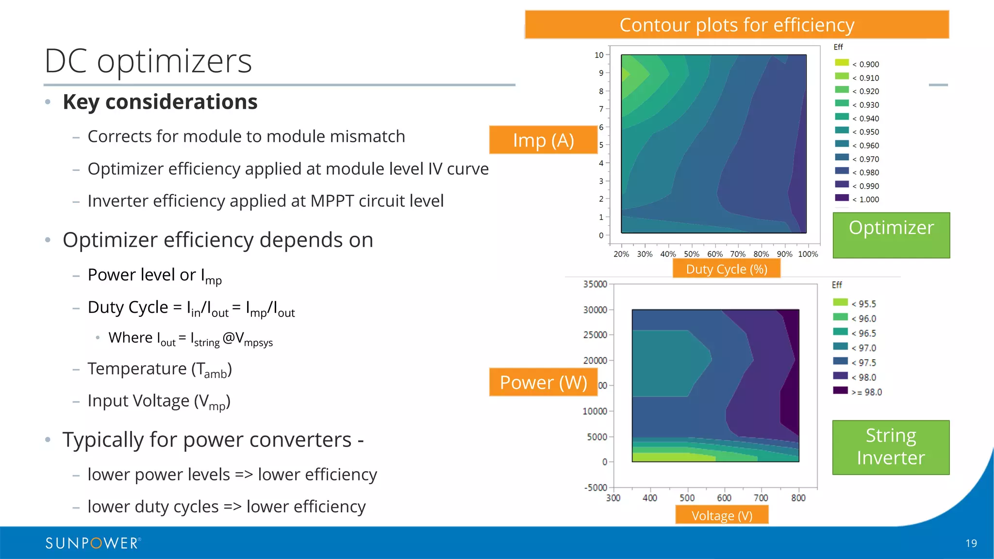
DC optimizers - equations
Where
Isys : PV system current (A)
Vmpsys : Voltage at max. power point - system level (V)
Imp : module current at max. power point (A)
Pmpmod , Vmpmod , Impmod : module power, voltage and current at max. power point
OptEff(duty cycle, input current) : optimizer efficiency at given duty cycle and input current (%)
StrInvEff(power, voltage) : string inverter efficiency at given input power and voltage (%)
Psys : System Power
𝐷𝑢𝑡𝑦𝐶𝑦𝑐𝑙𝑒 𝑛 = 𝐼 𝑚𝑝 𝑛
𝐼 𝑠𝑡𝑟𝑖𝑛𝑔 𝑠𝑡𝑟
… (2) j
𝑃 𝑚𝑜𝑑 𝑛 = 𝑃 𝑚𝑝𝑚𝑜𝑑[𝑛] ∗ 𝑂𝑝𝑡𝐸𝑓𝑓(𝐷𝑢𝑡𝑦𝐶𝑦𝑙𝑒 𝑛 , 𝐼 𝑚𝑝𝑚𝑜𝑑 𝑛 ) … (3)
𝐼 𝑠𝑡𝑟𝑖𝑛𝑔 𝑠𝑡𝑟 = 𝐼 𝑠𝑦𝑠 𝑉 𝑚𝑝𝑠𝑦𝑠
… (1)
𝑃 𝑠𝑦𝑠 = (' 𝑃 𝑚𝑜𝑑 𝑛 ) × 𝑆𝑡𝑟𝐼𝑛𝑣𝐸𝑓𝑓 𝑃 𝑚𝑝𝑚𝑜𝑑 𝑛 , 𝑉 𝑚𝑝𝑚𝑜𝑑 𝑛 … (4)
5
678](https://image.slidesharecdn.com/pvpmcmlpechetanchaudhari-track32pmslotv2-190520154349/75/MLPE-performance-modeling-25-2048.jpg)