Download as ODP, PPTX
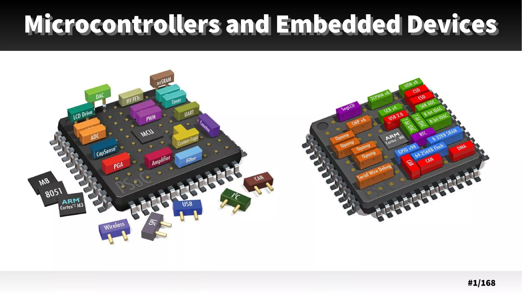


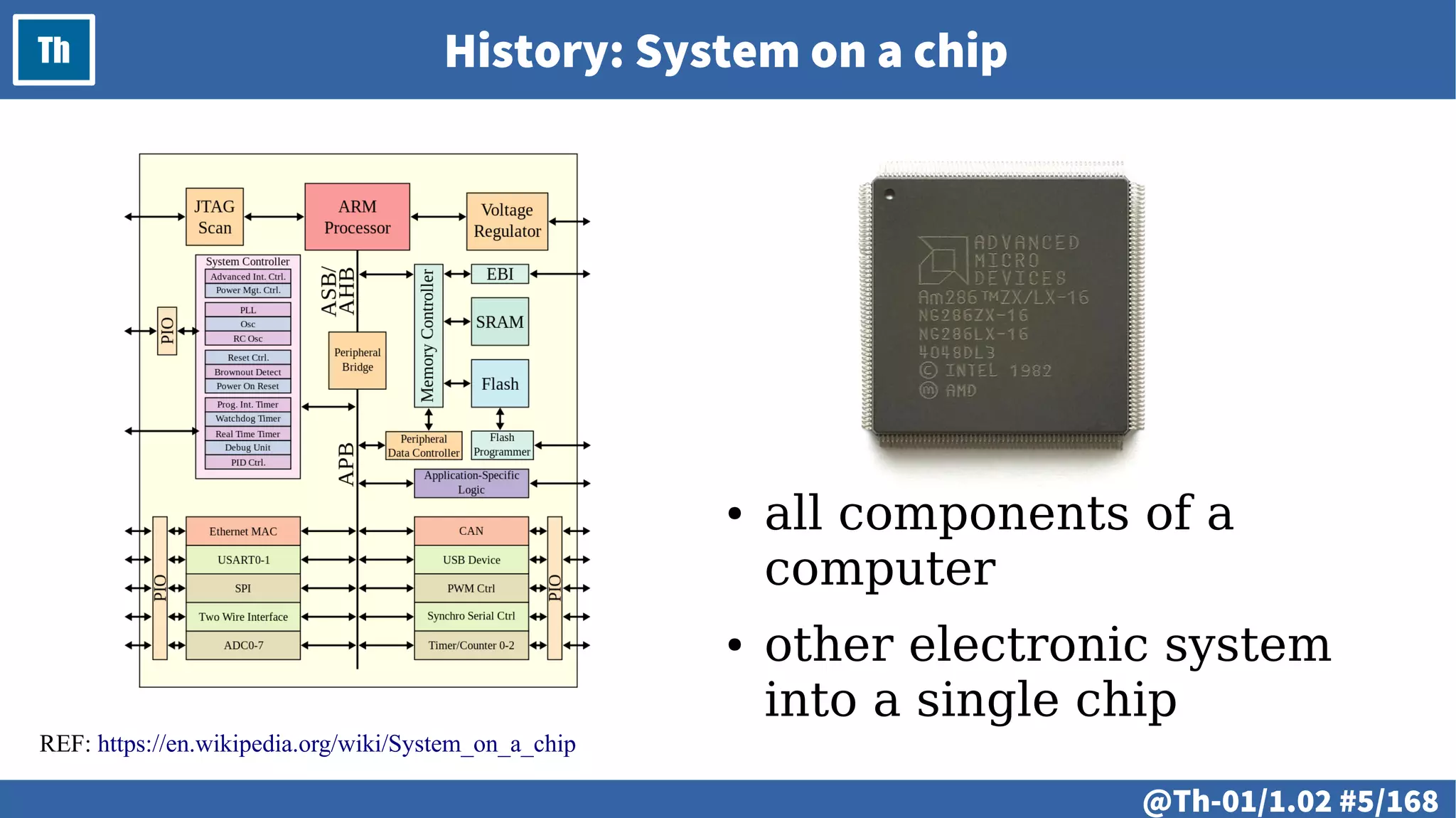
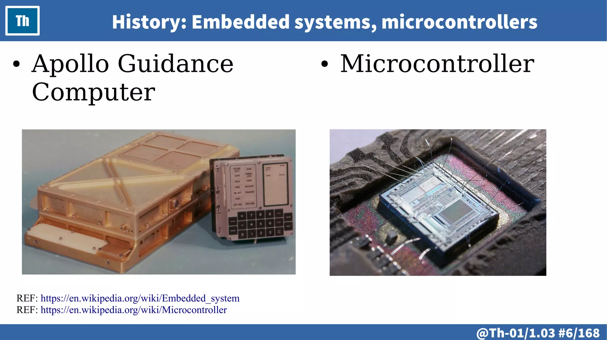
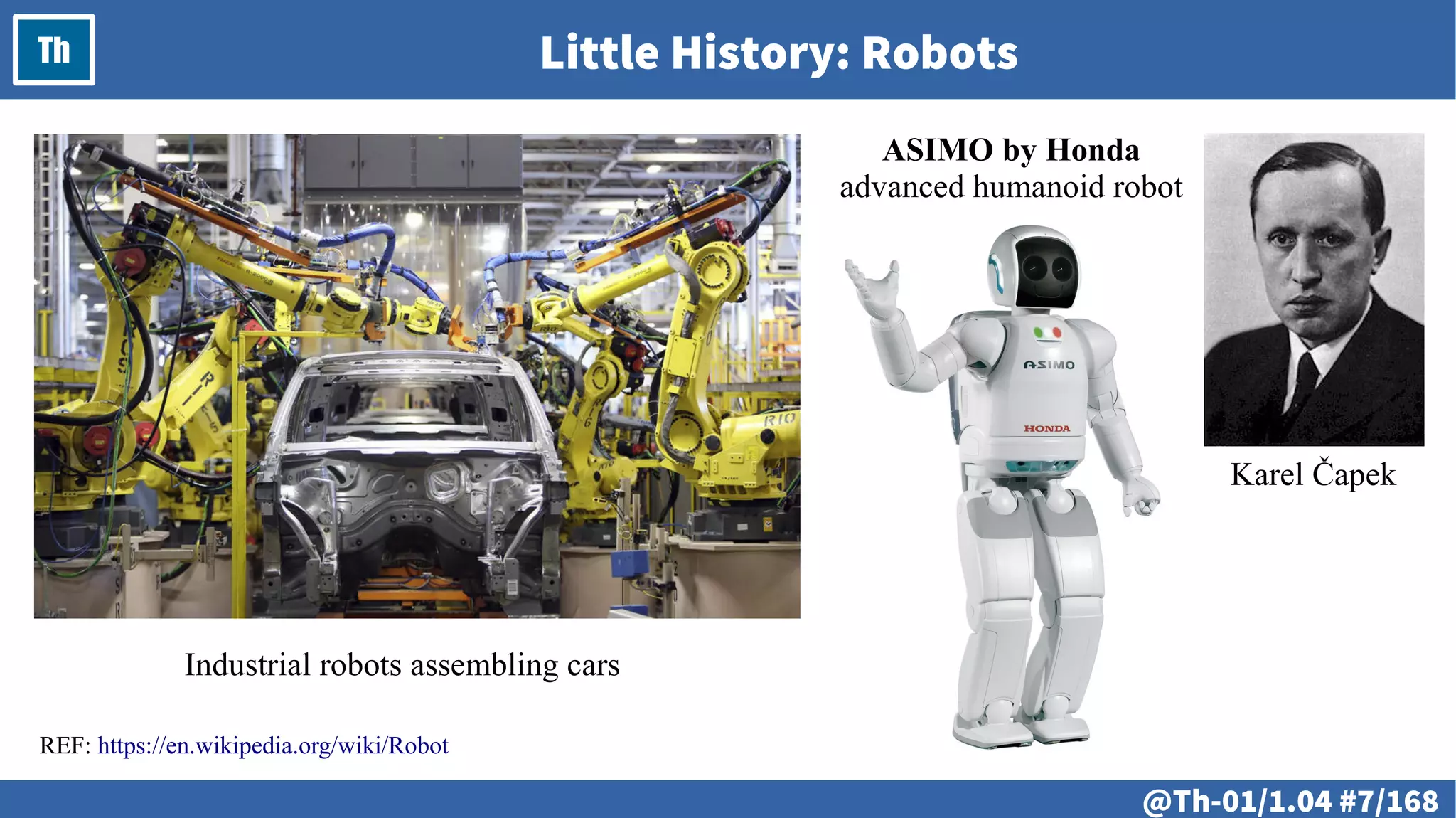
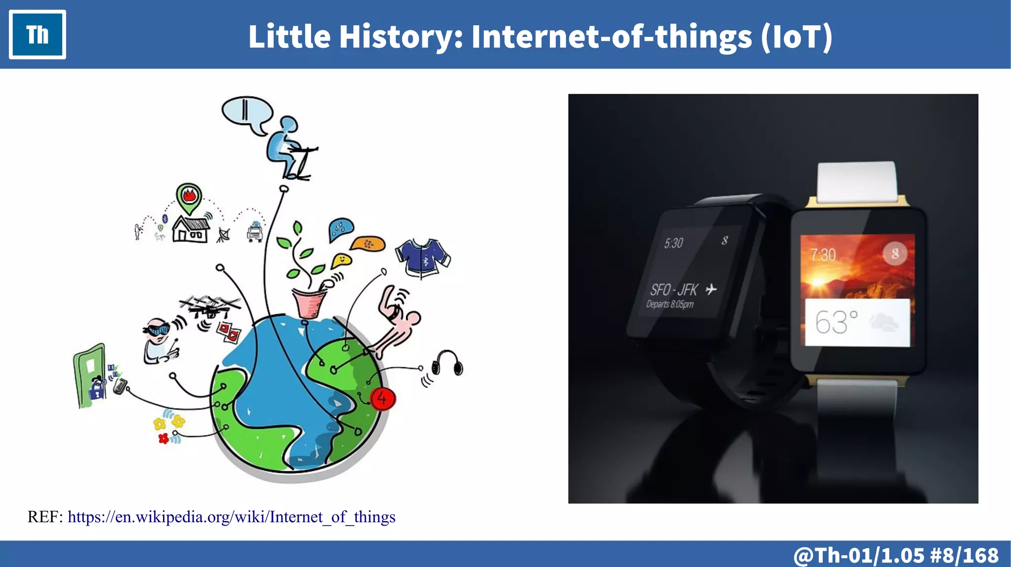

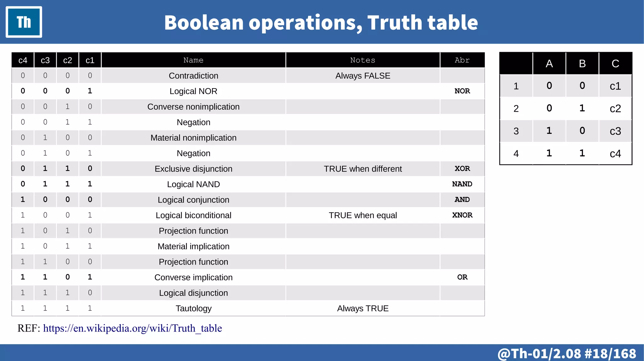
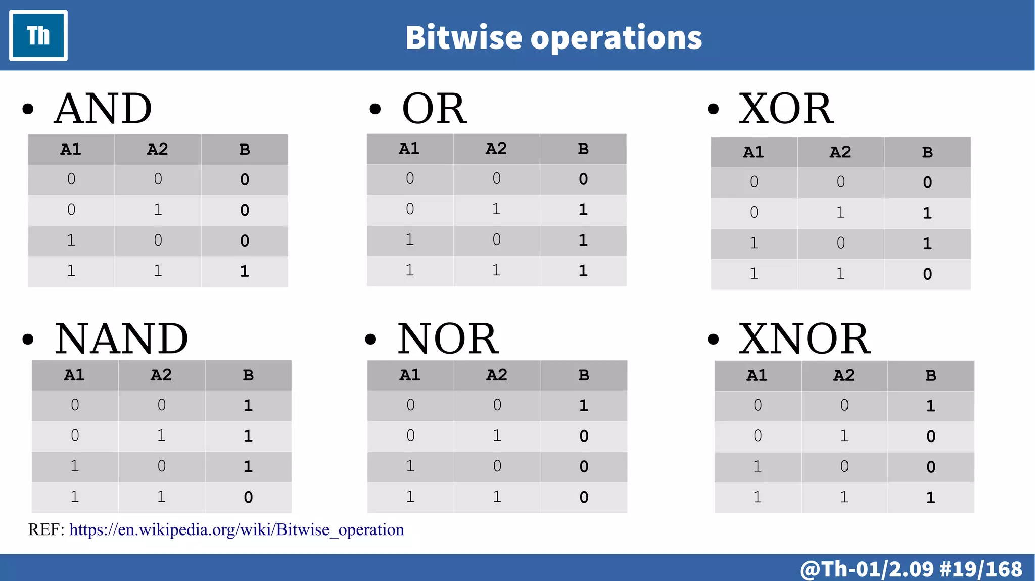
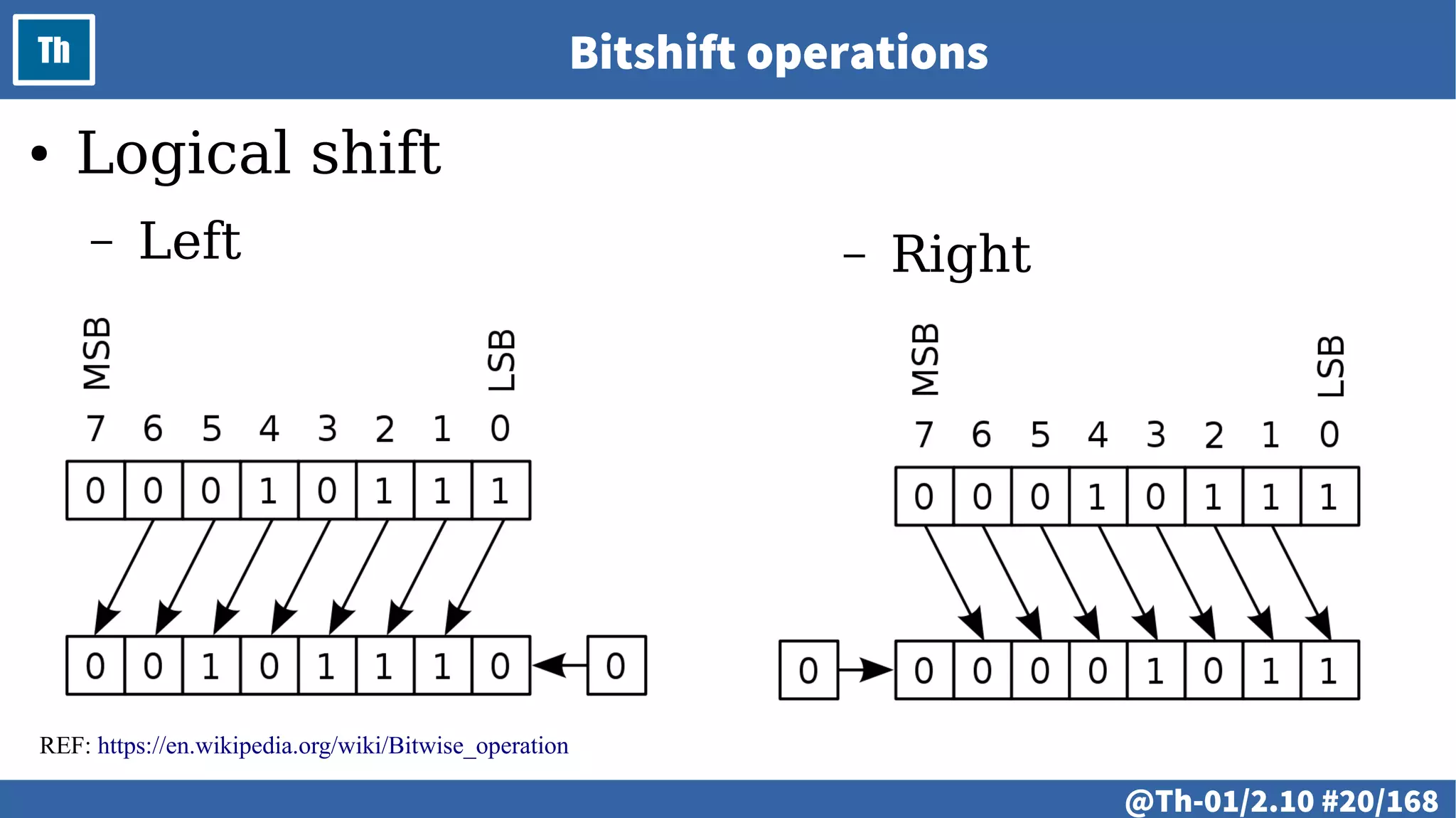
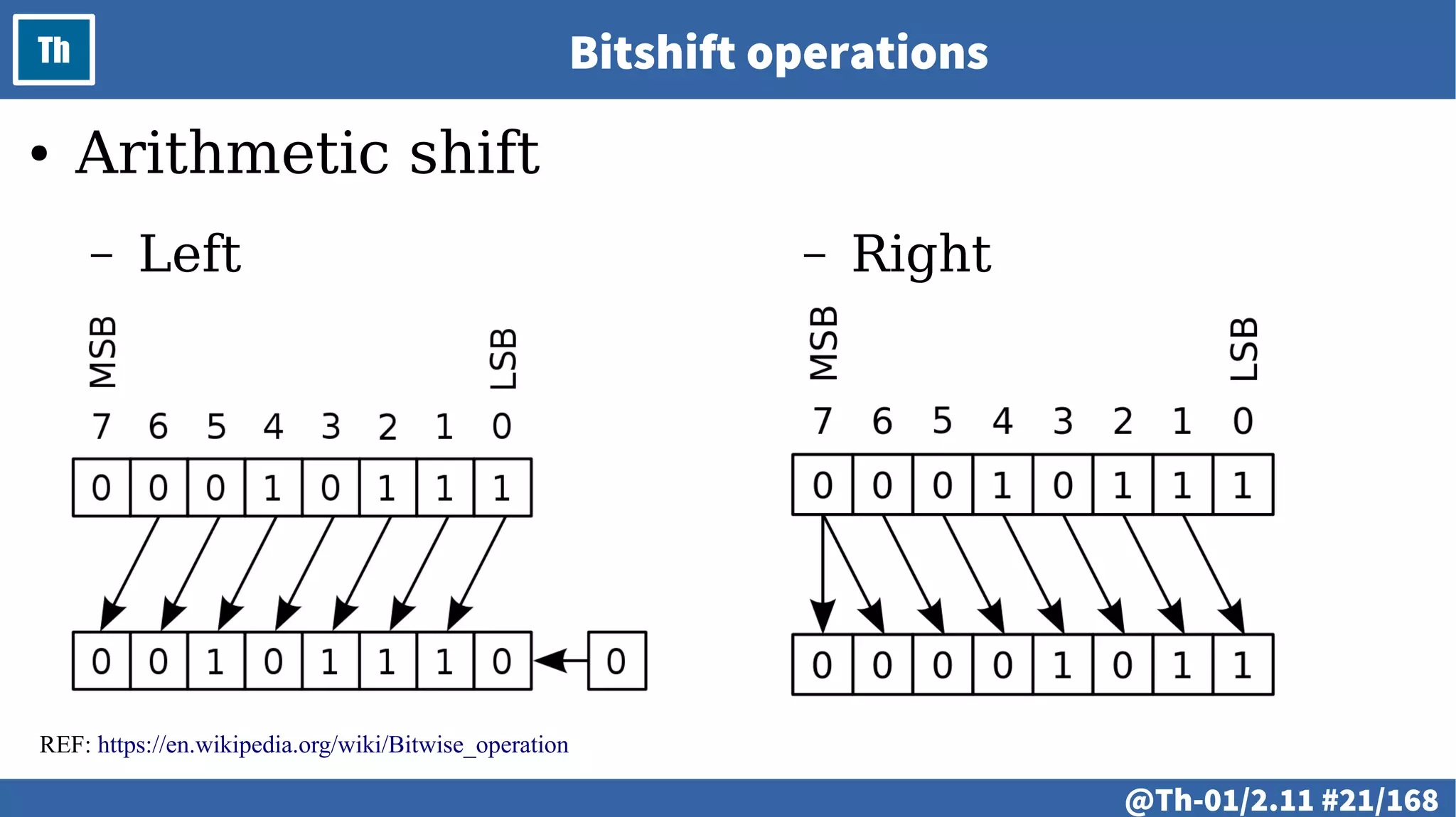
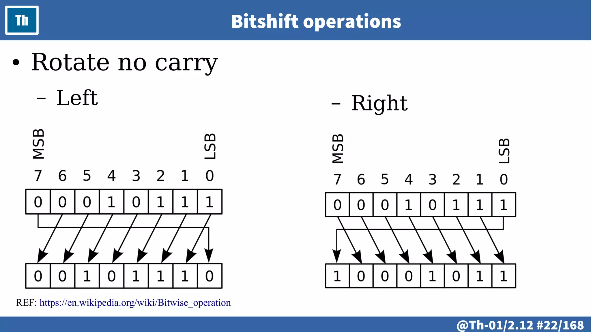
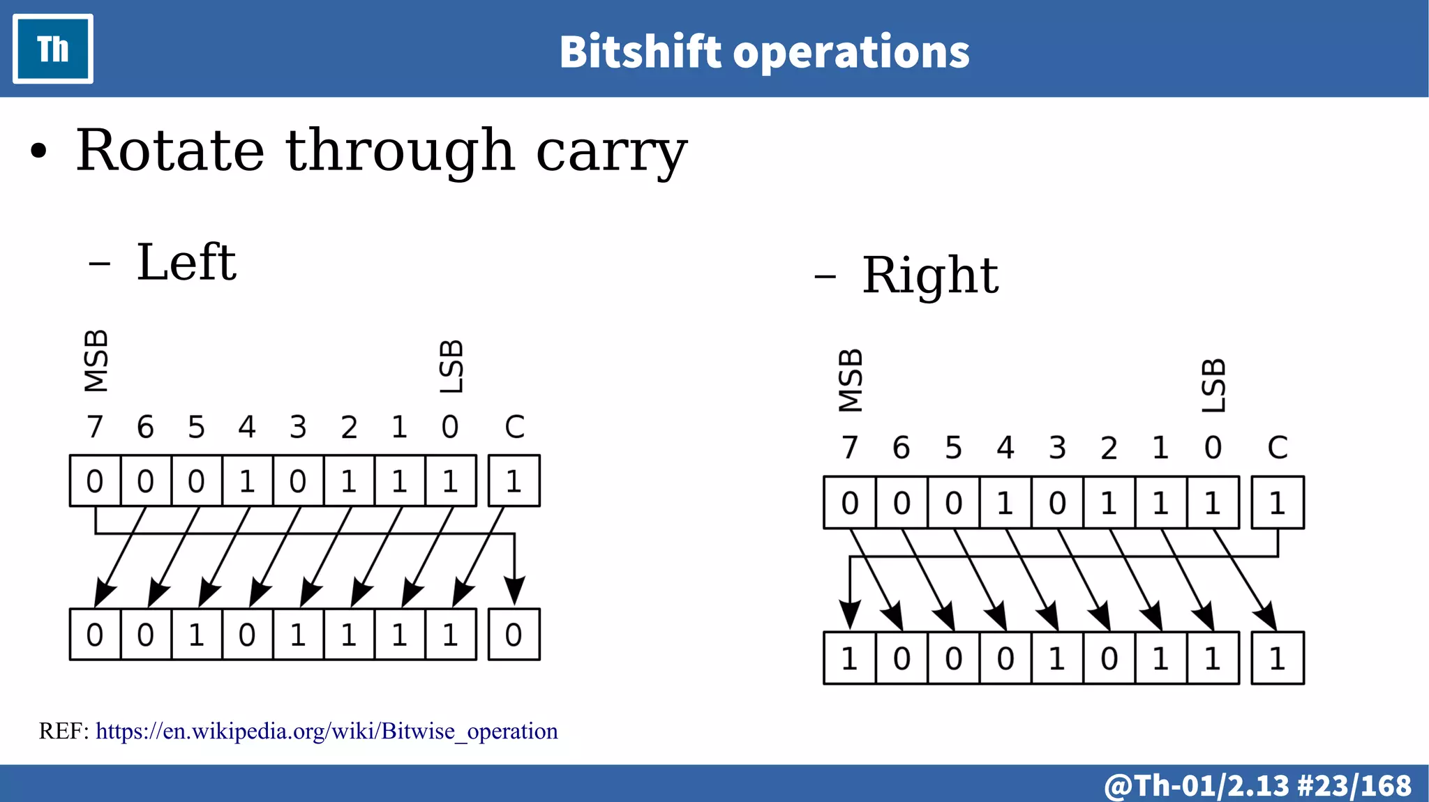

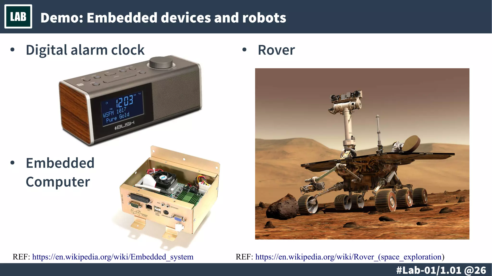
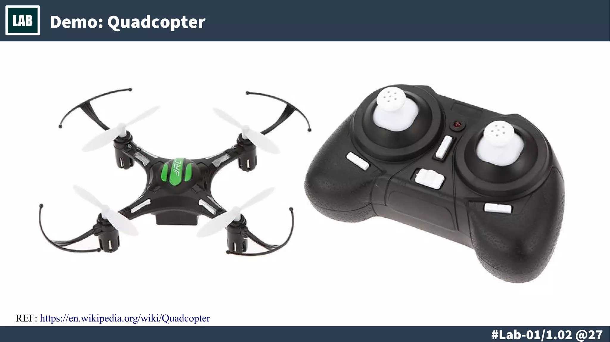
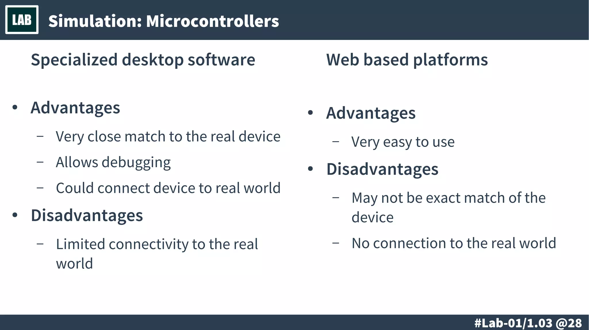
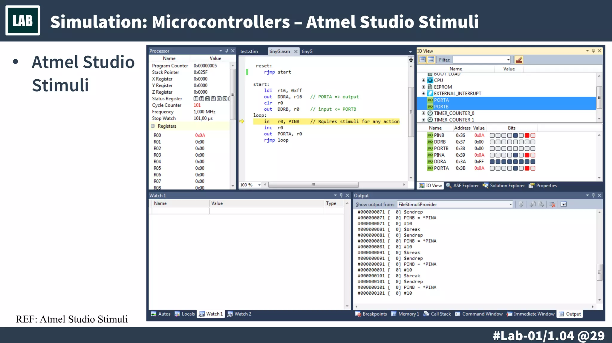
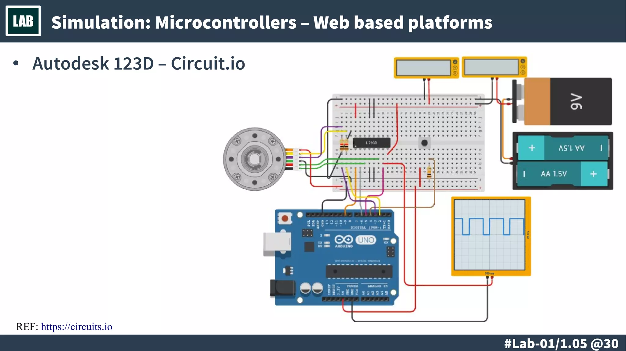
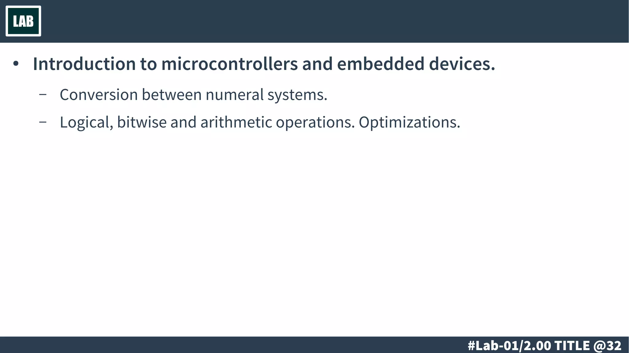
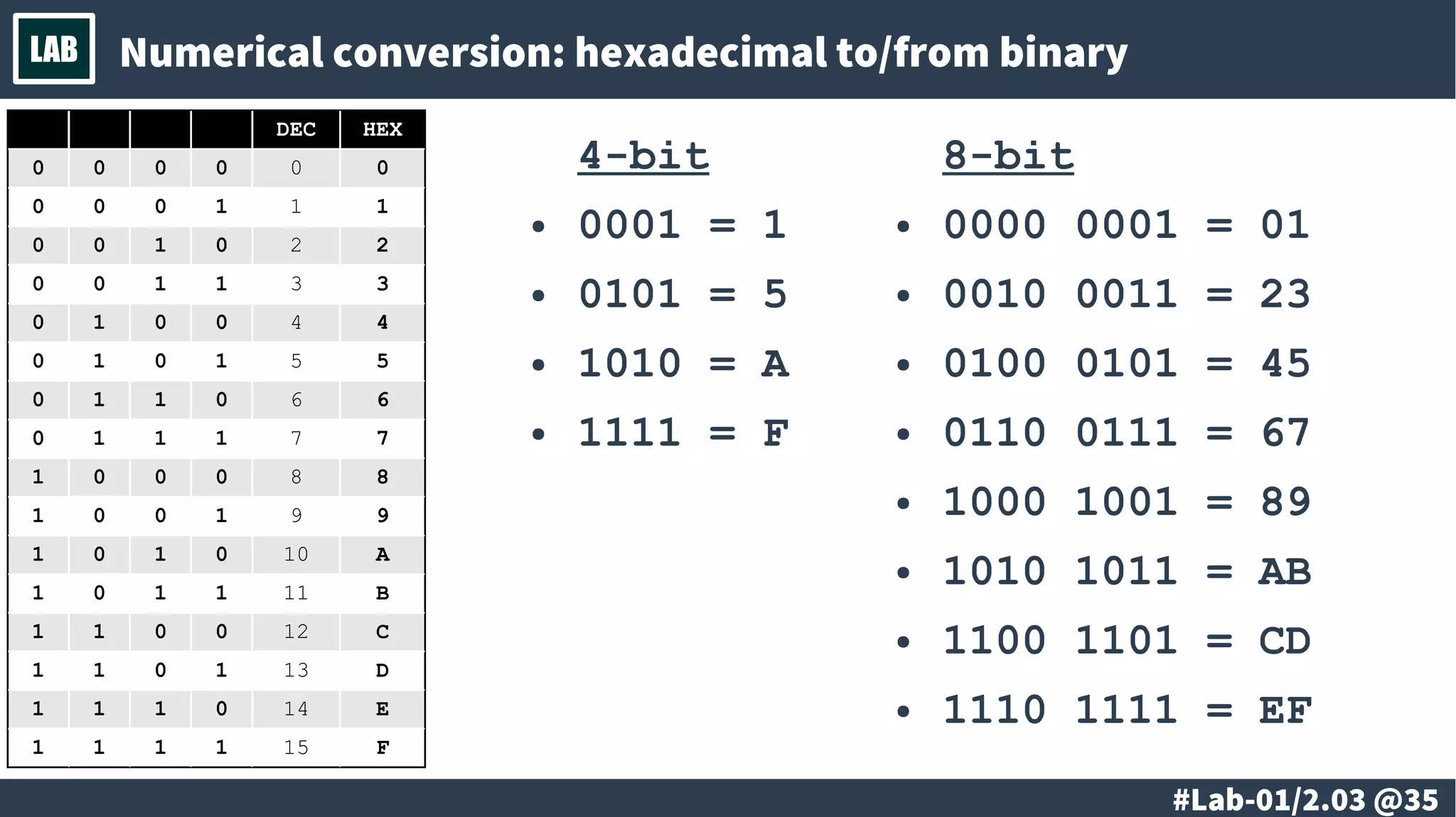
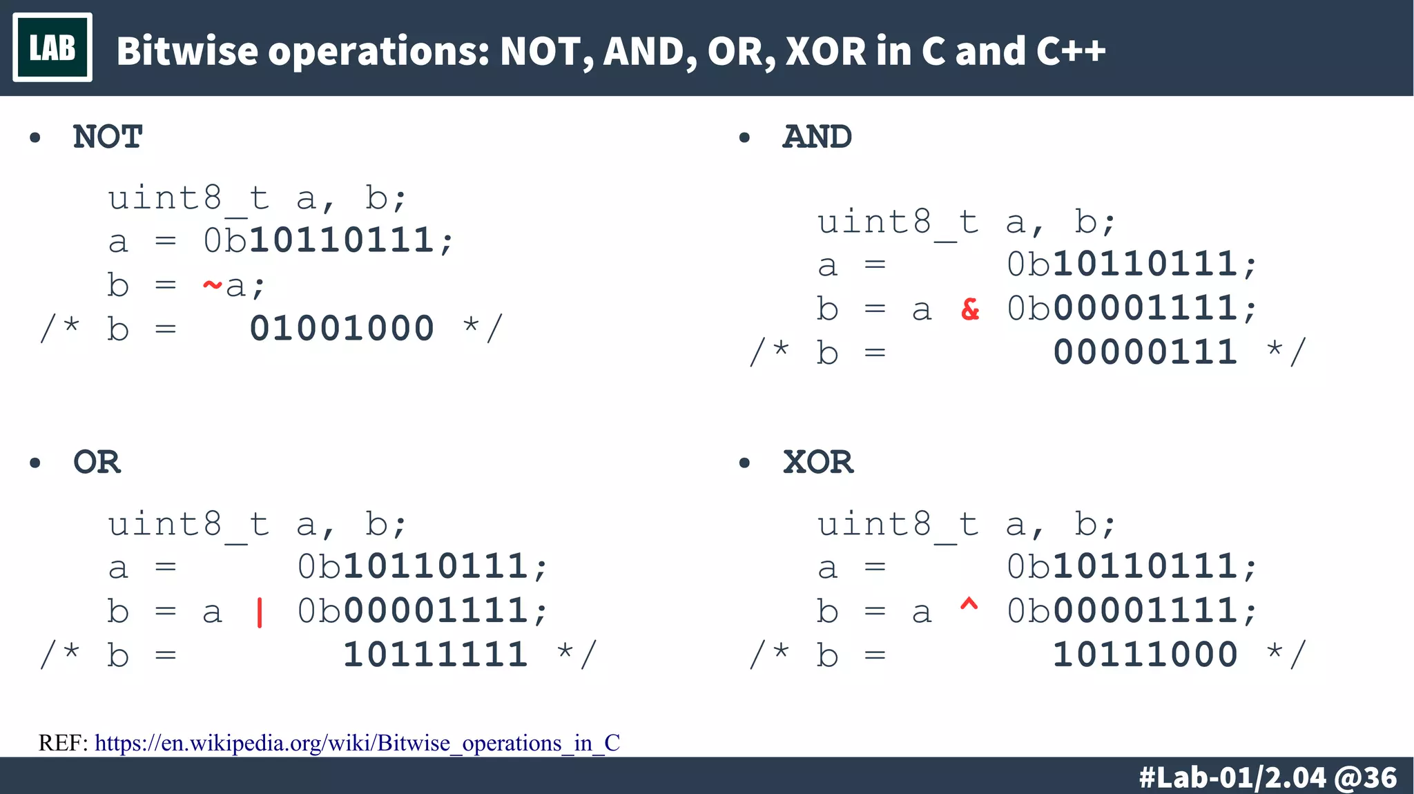
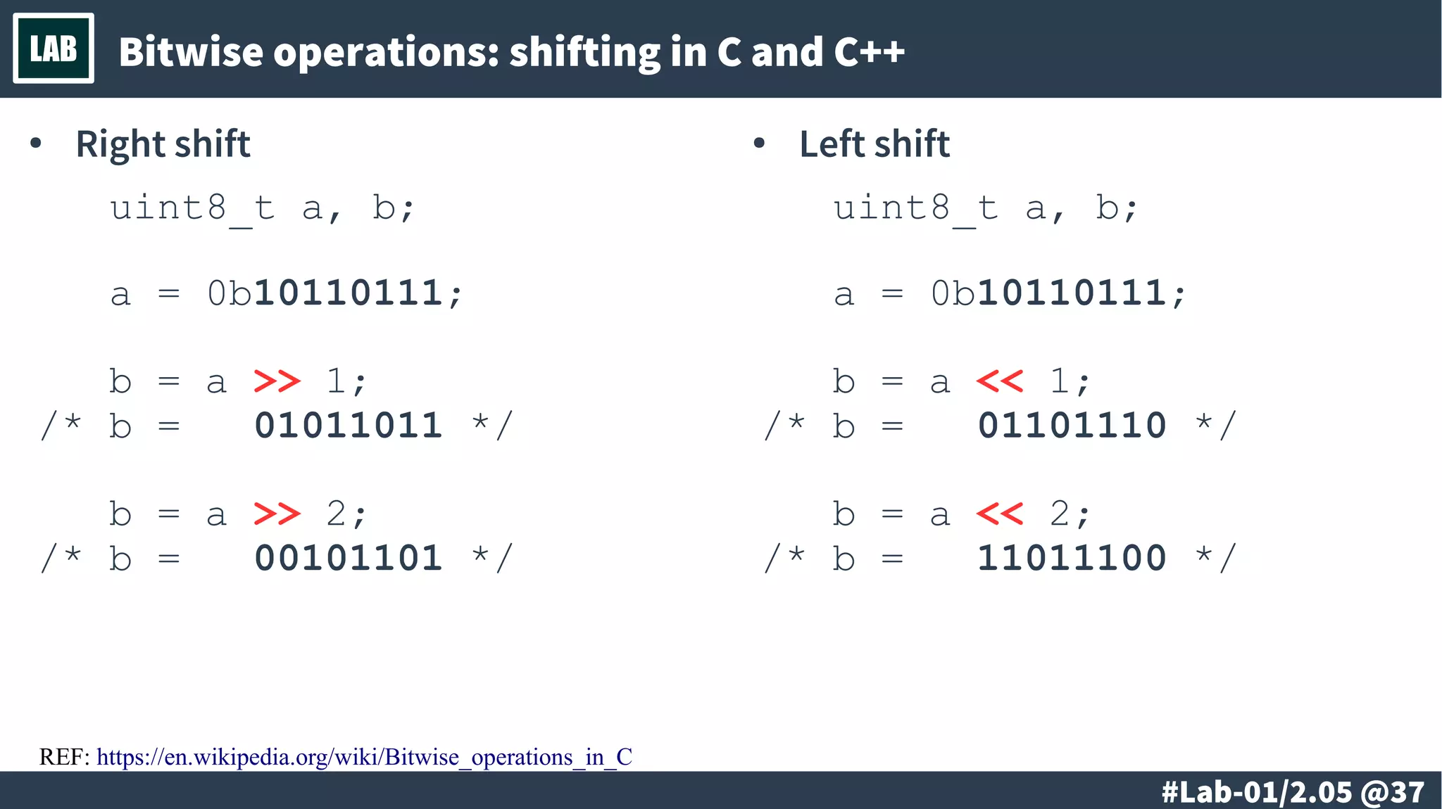
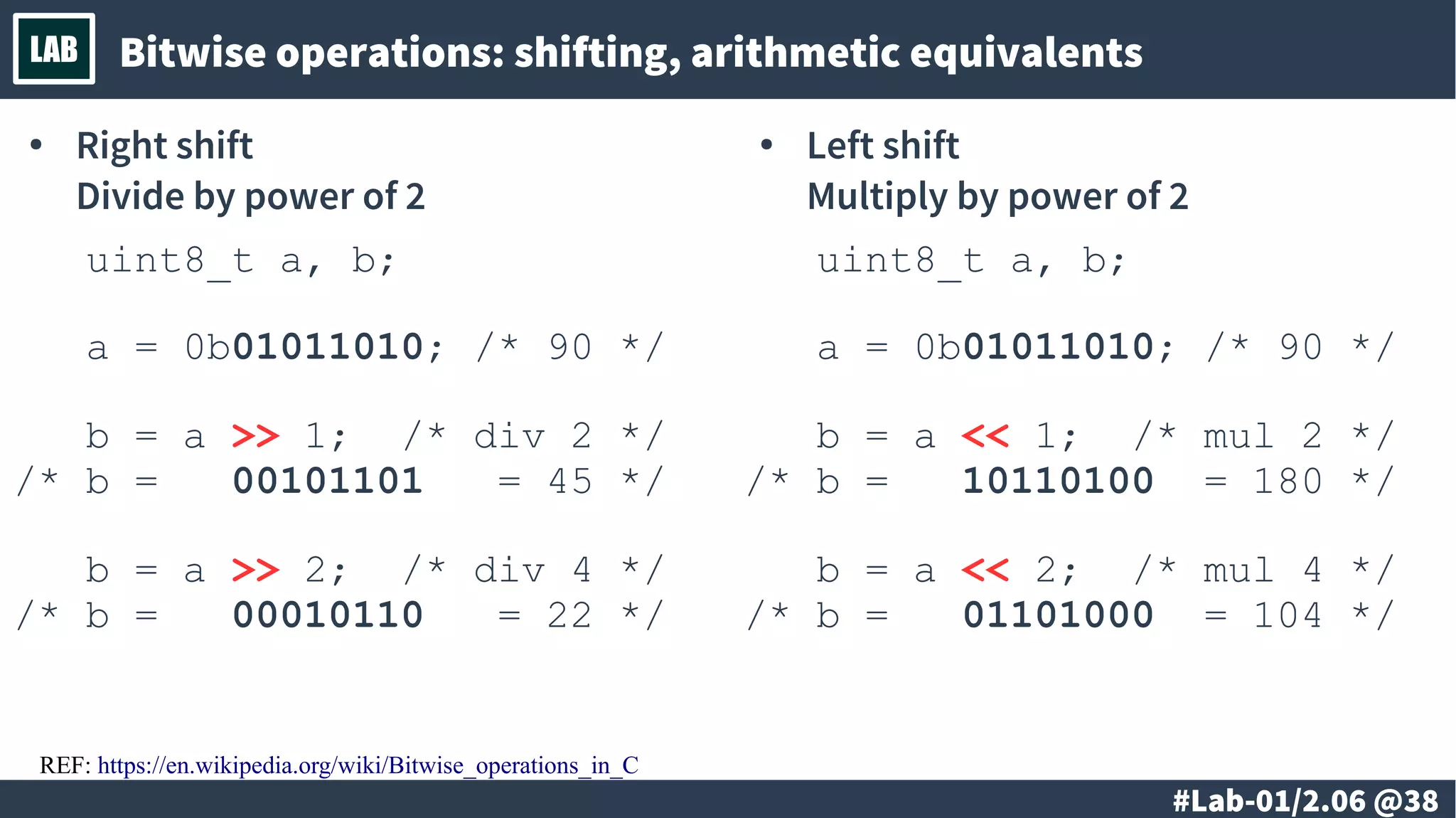
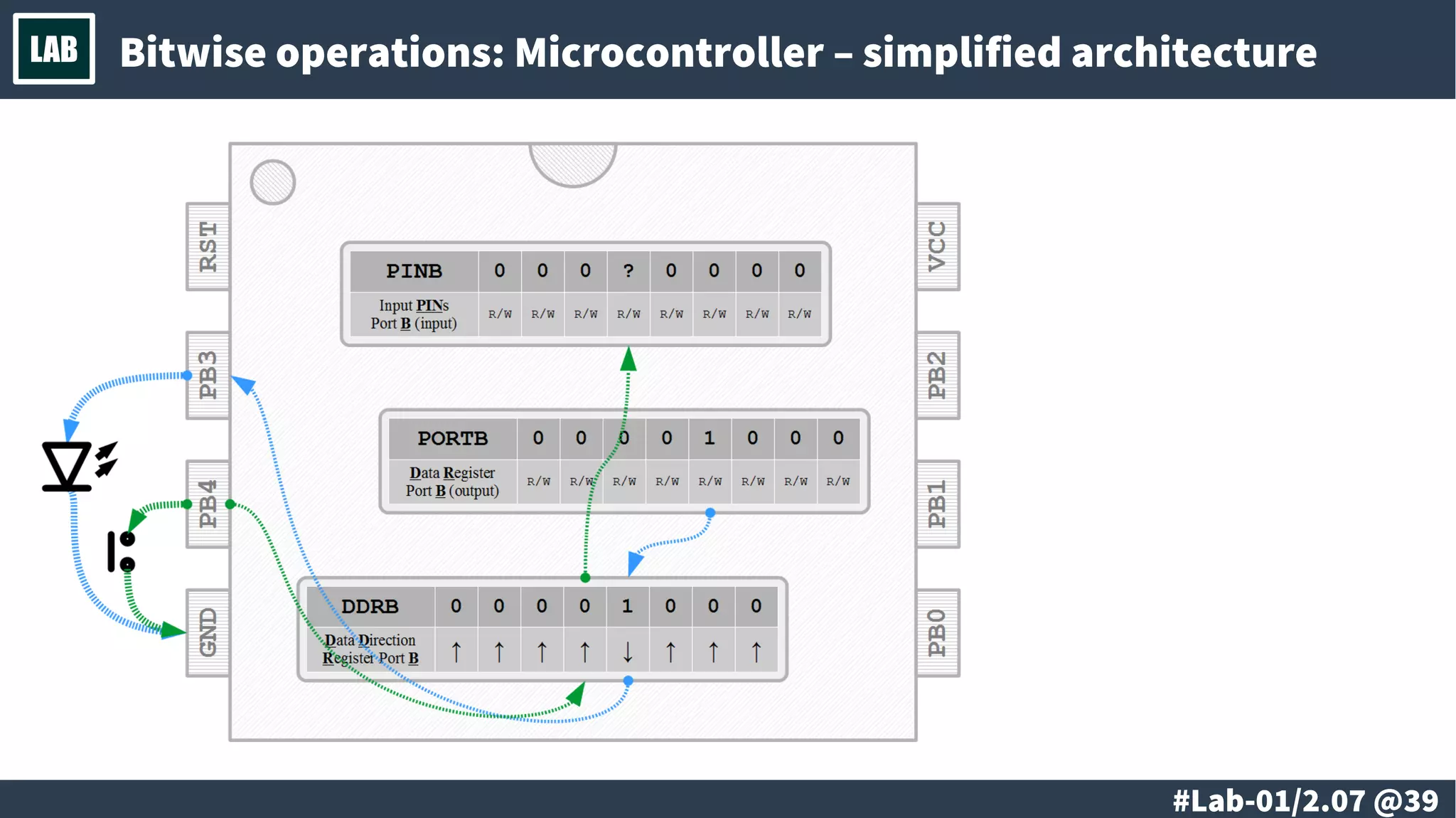
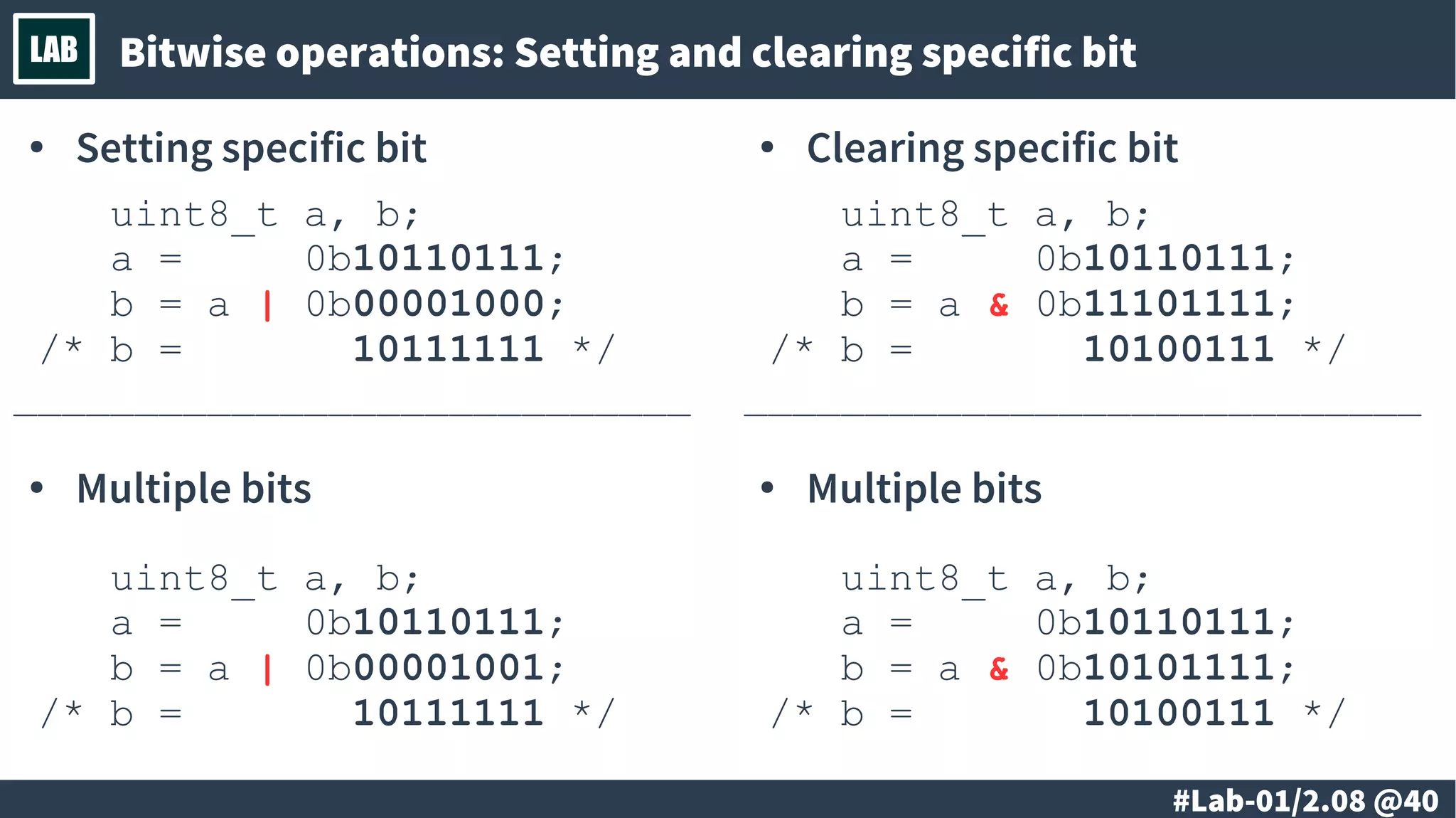
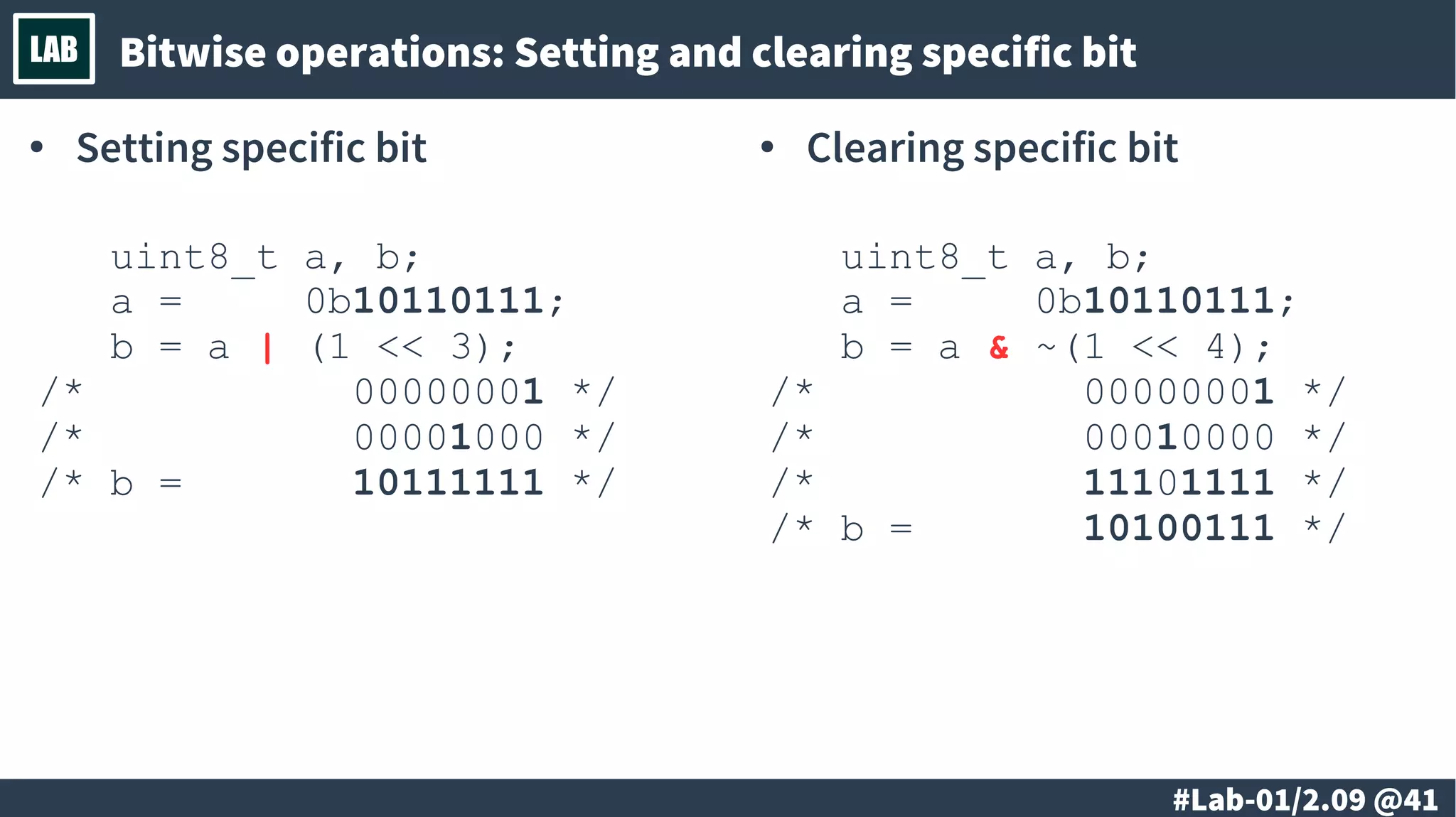
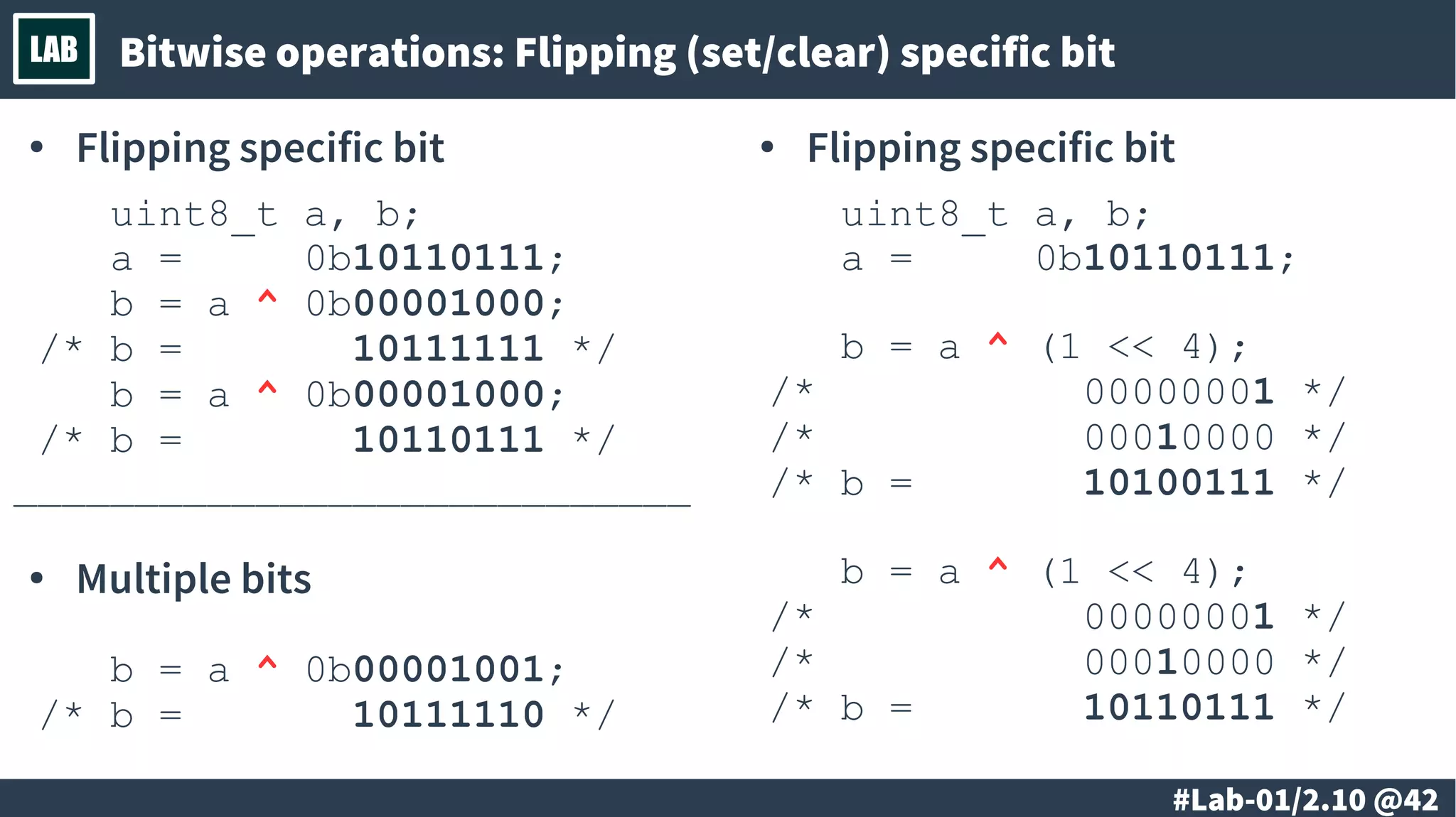
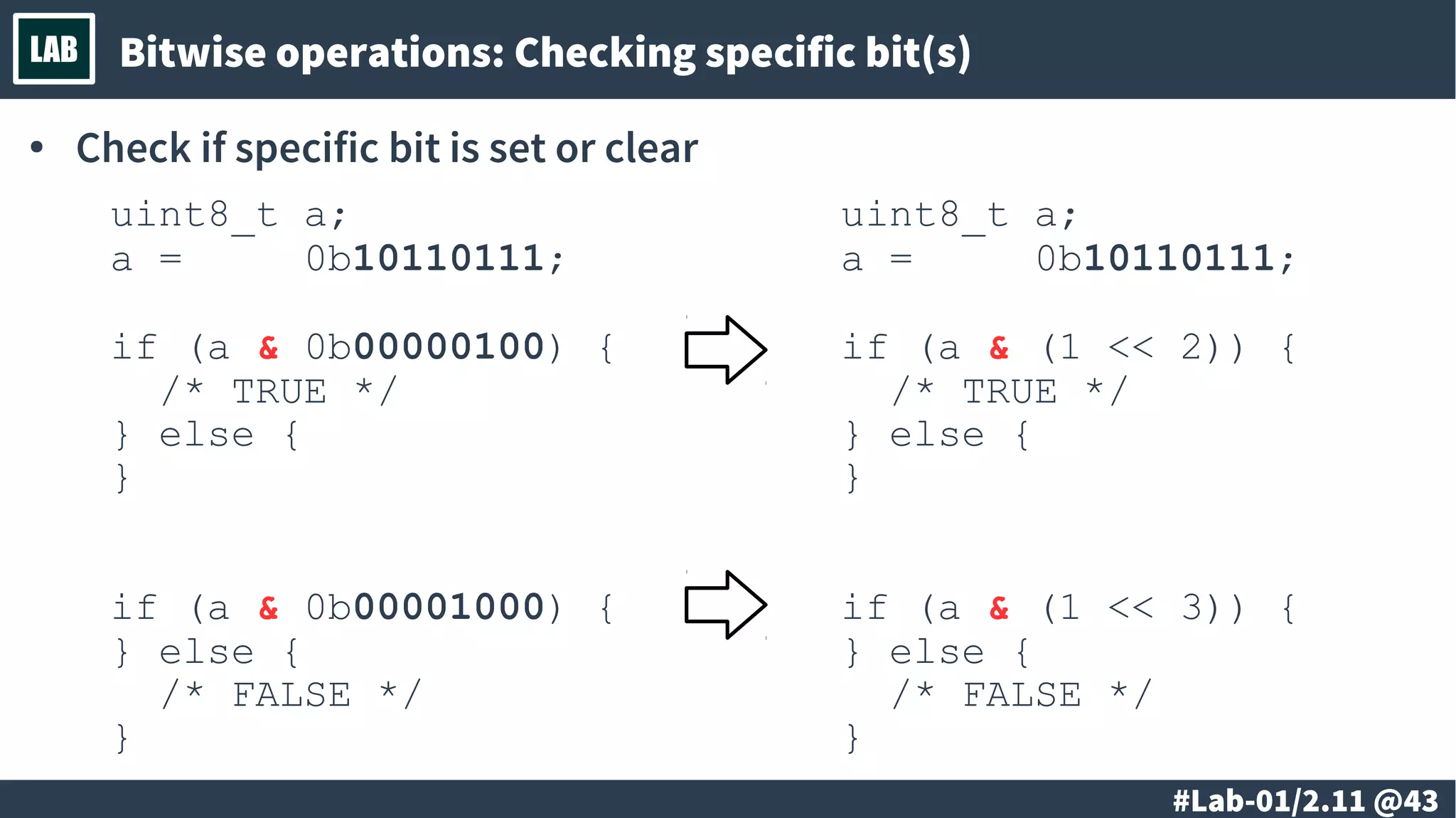

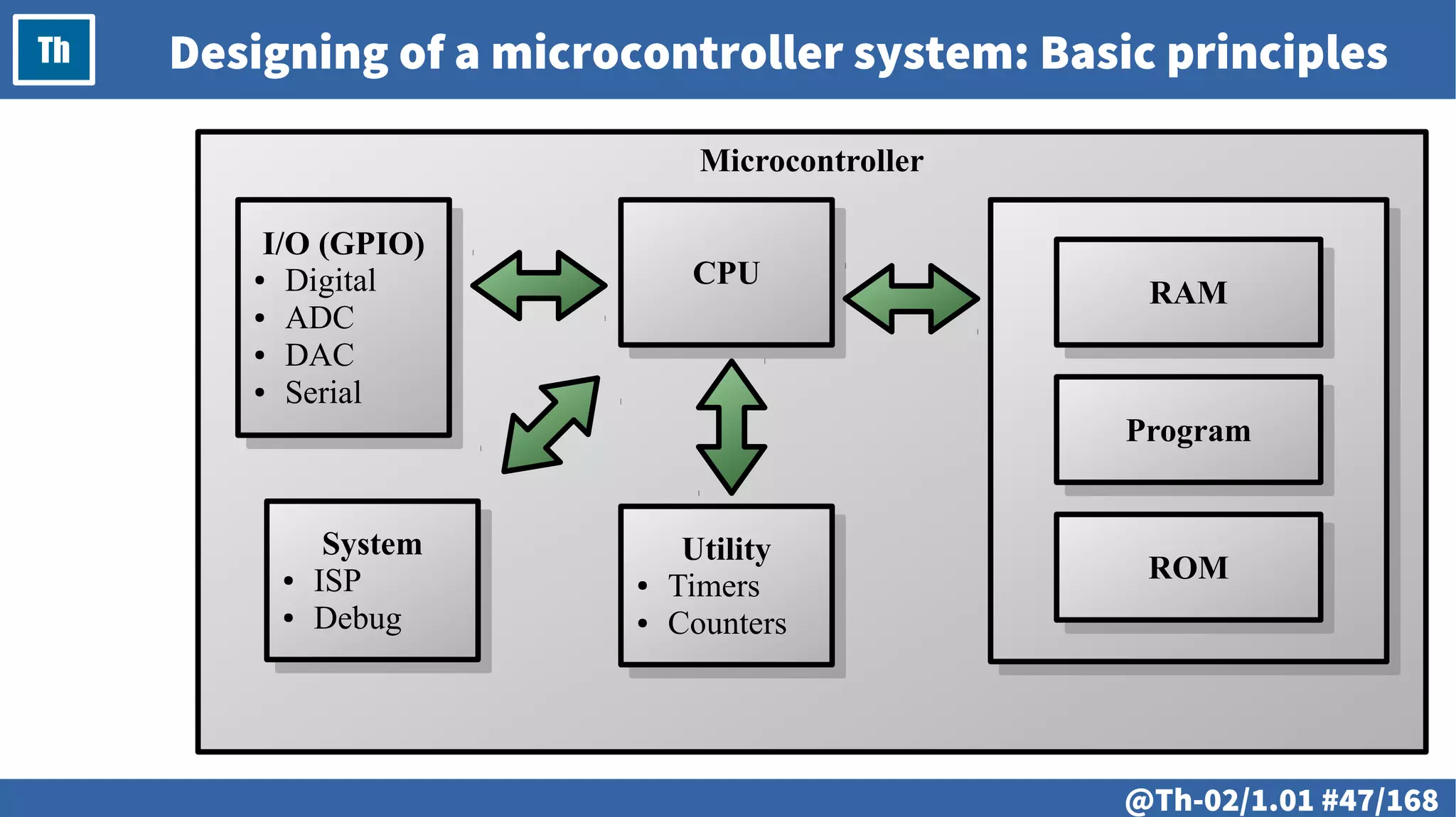
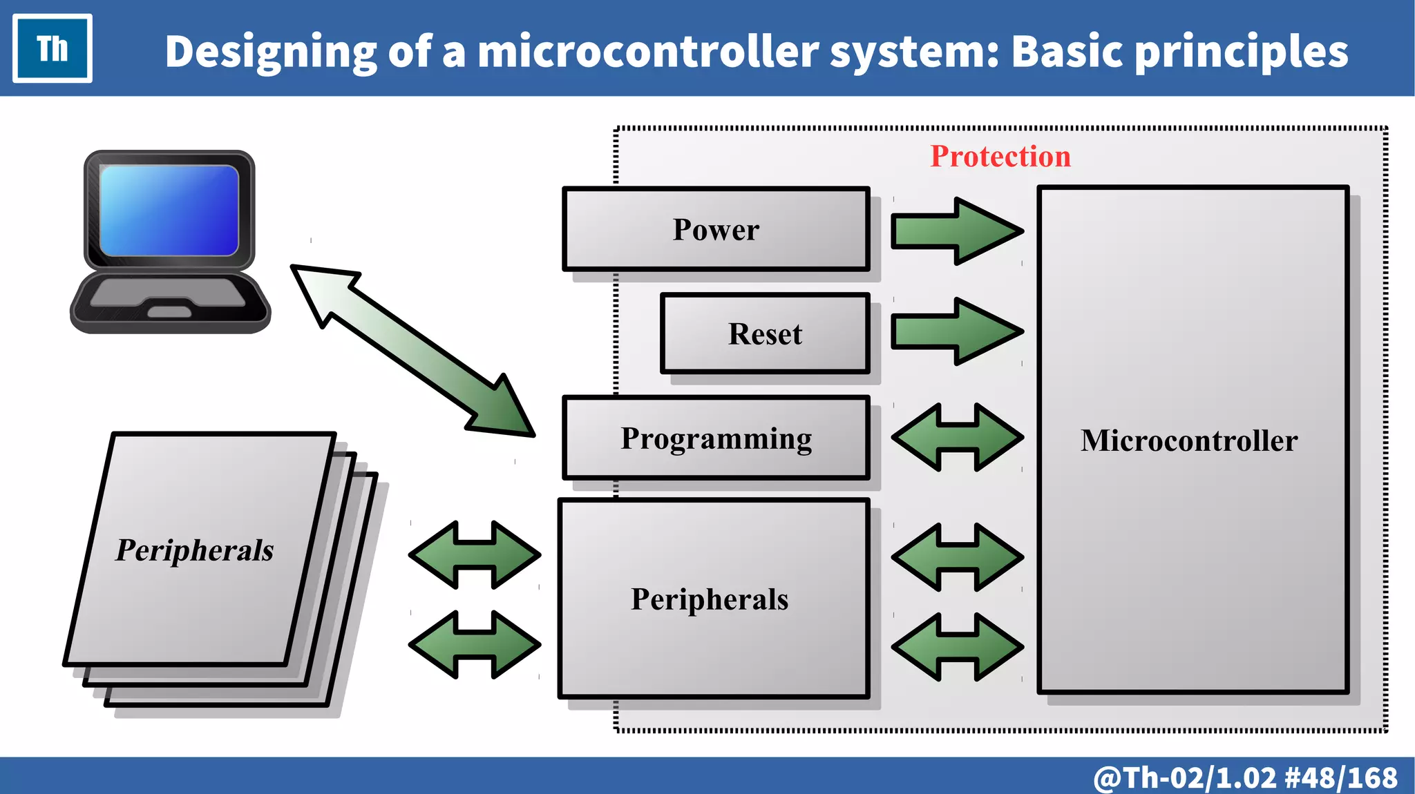

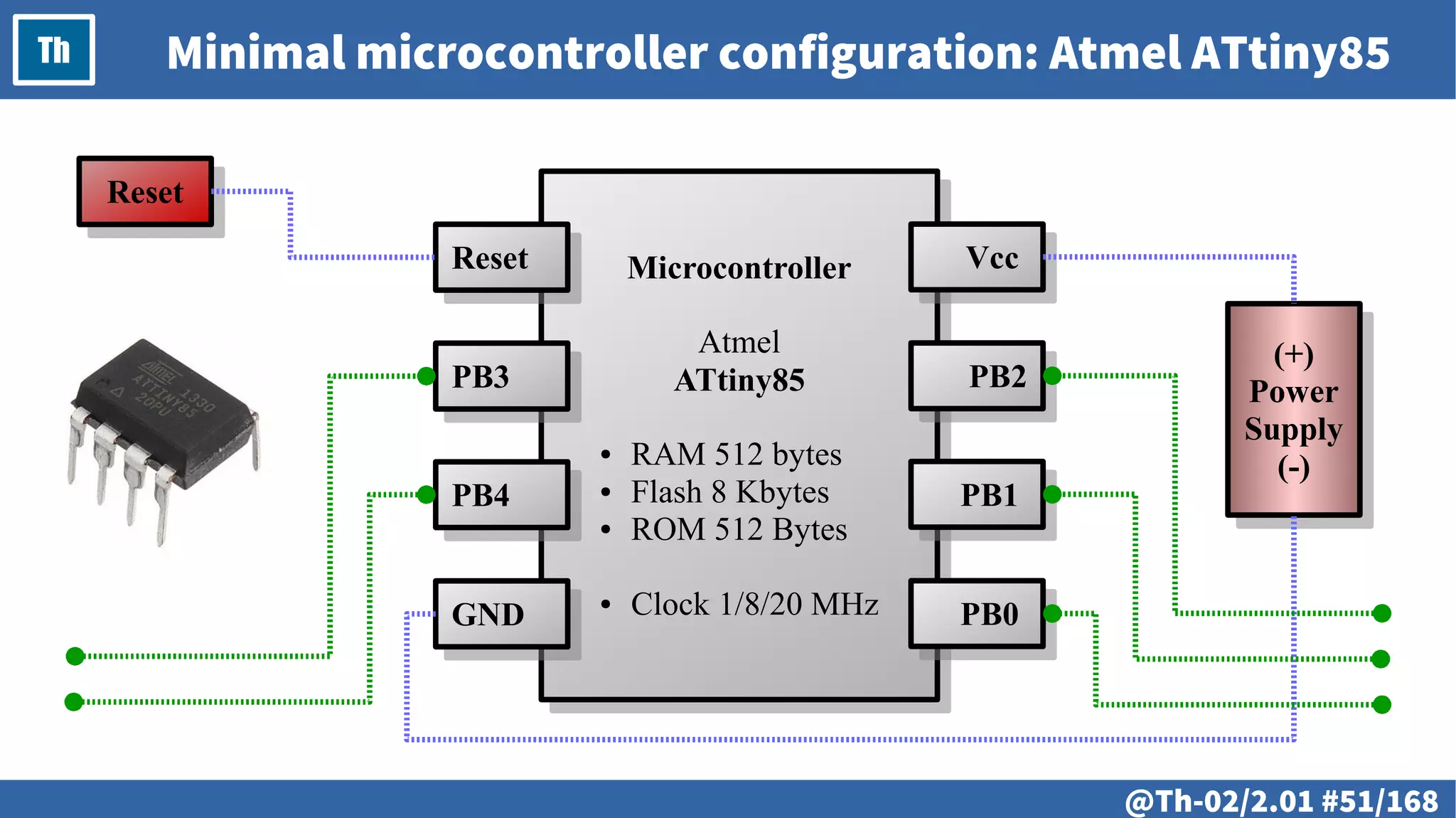
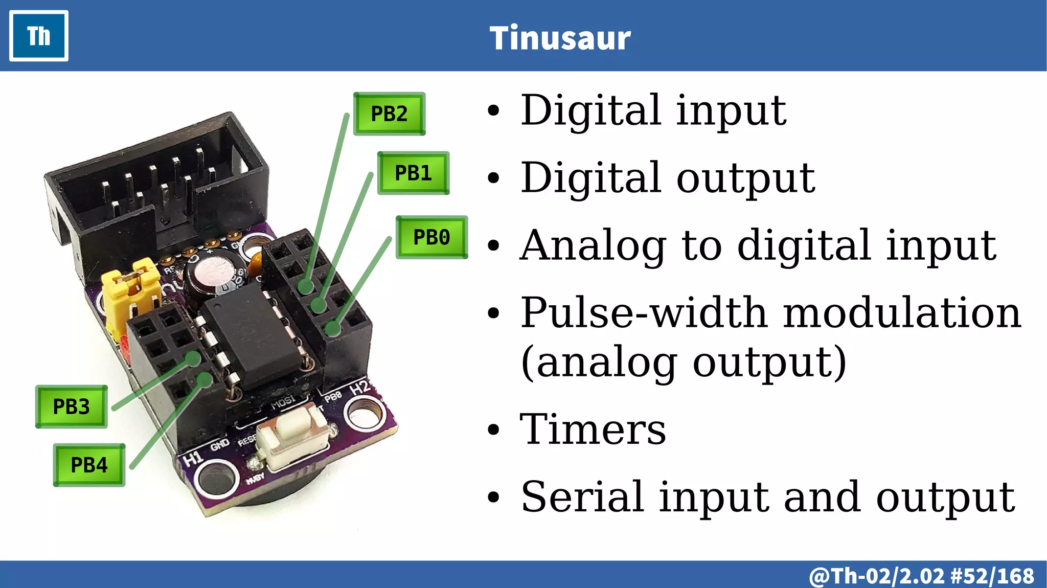


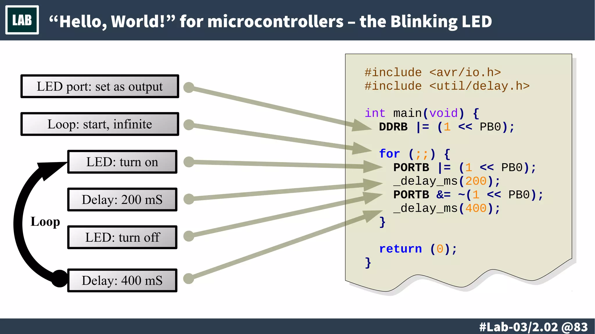
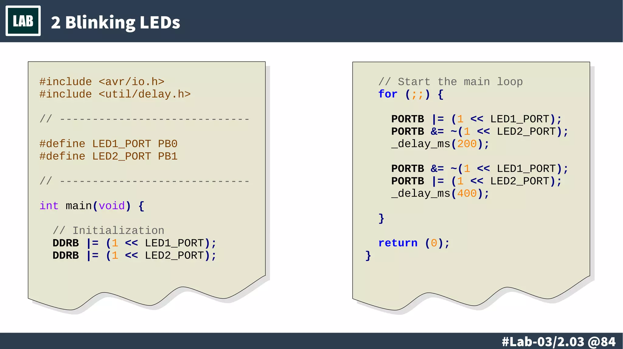
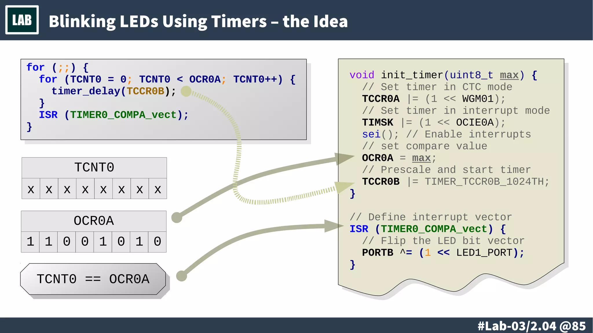

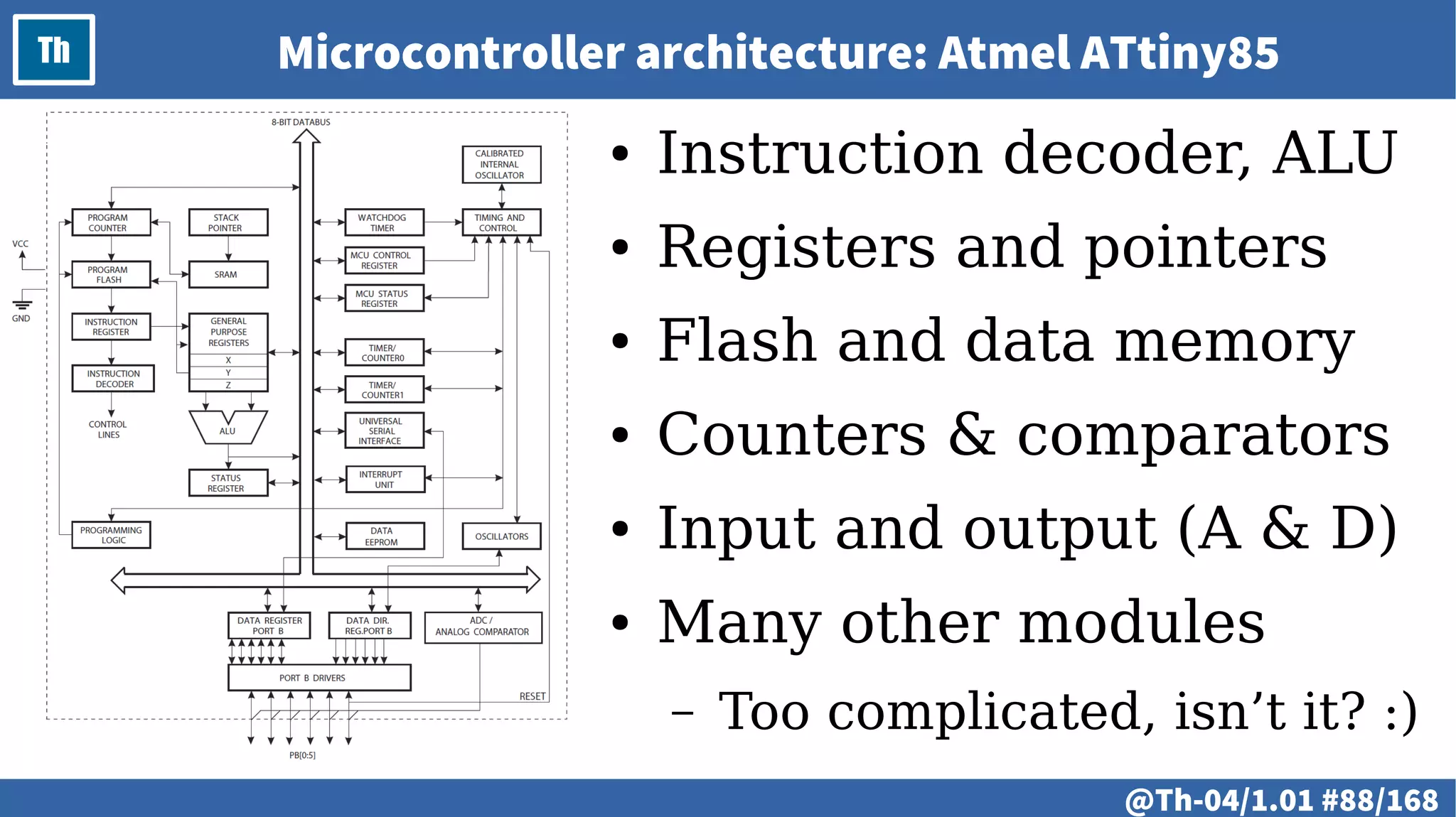
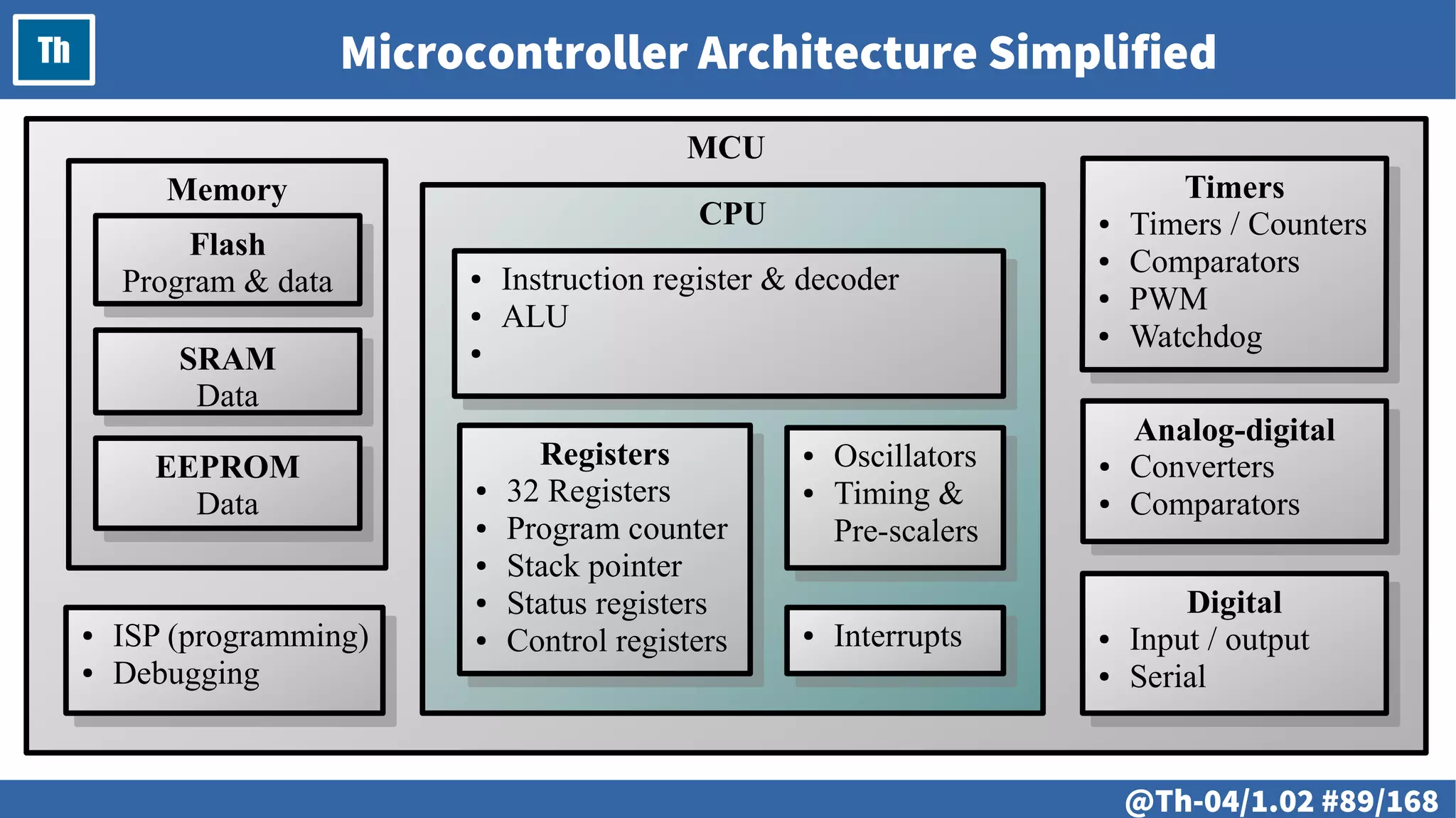
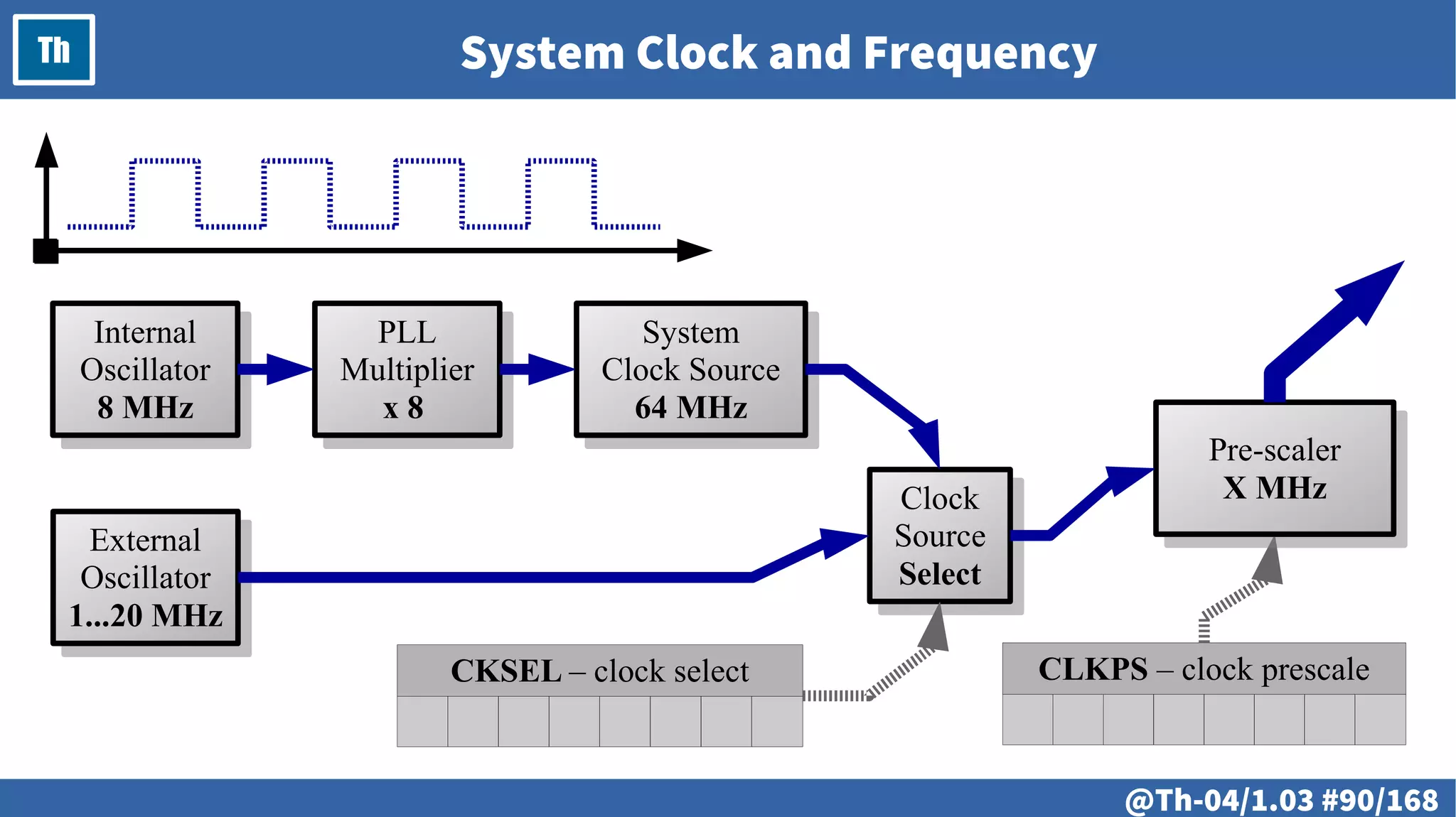
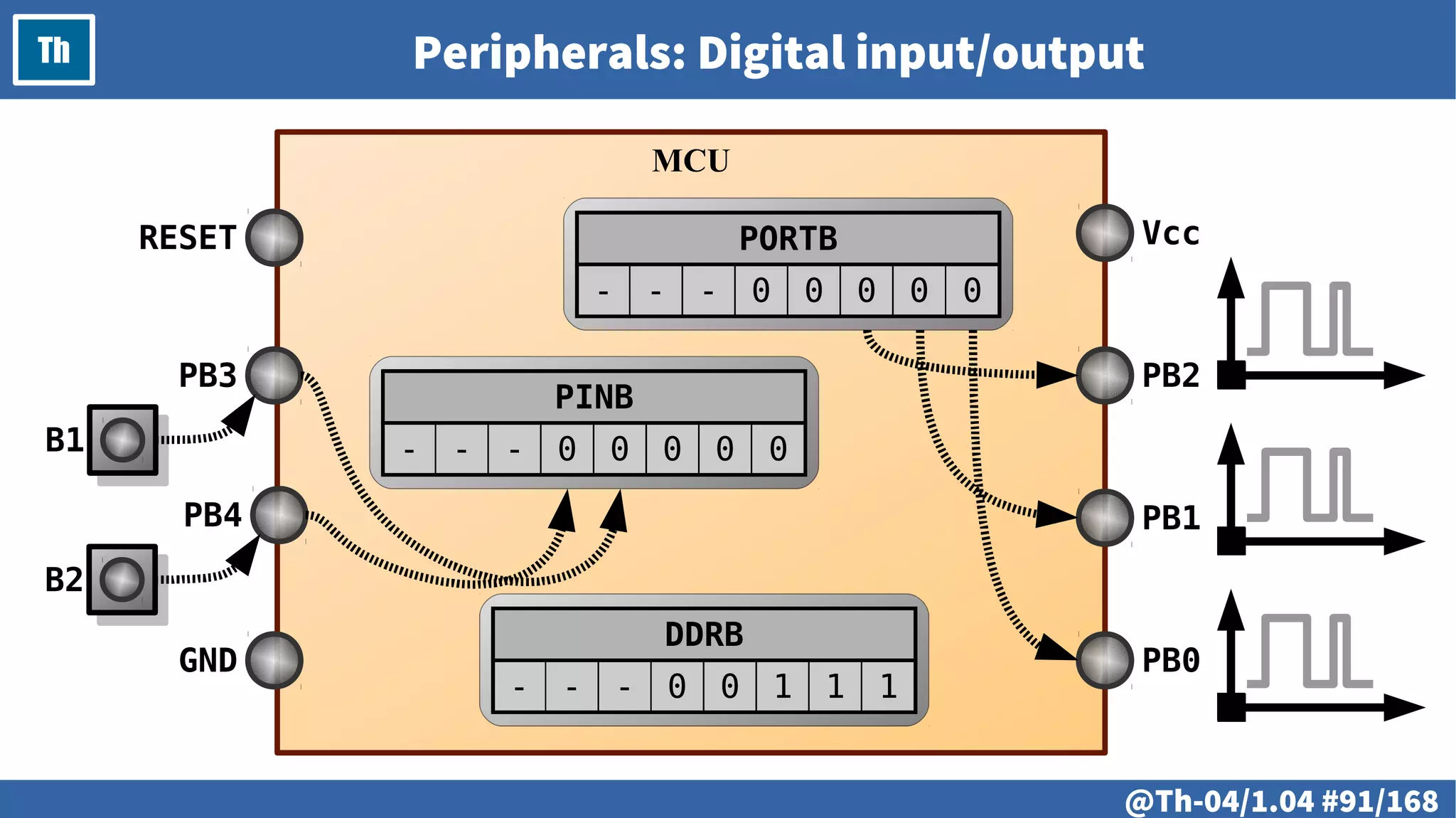


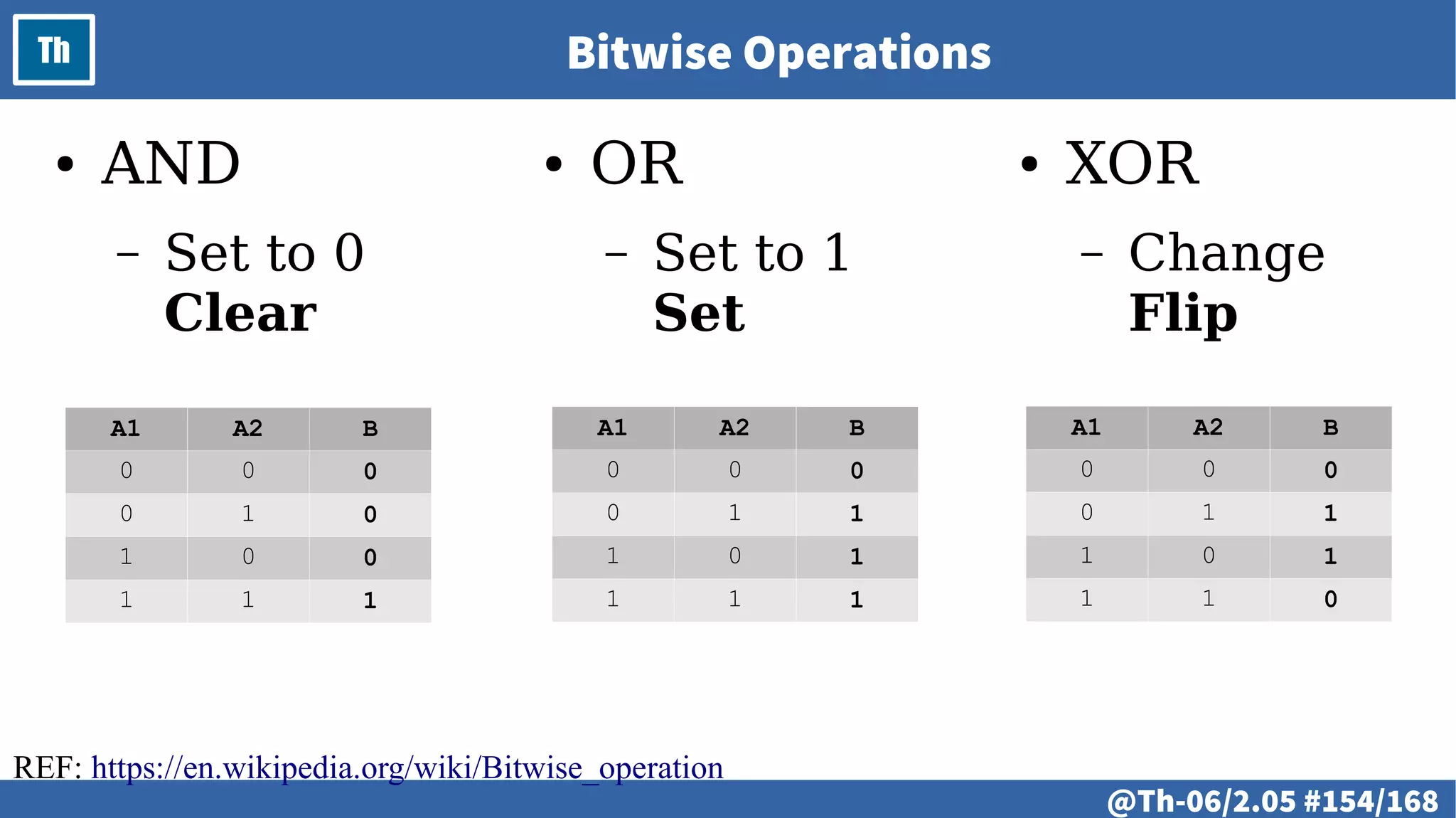

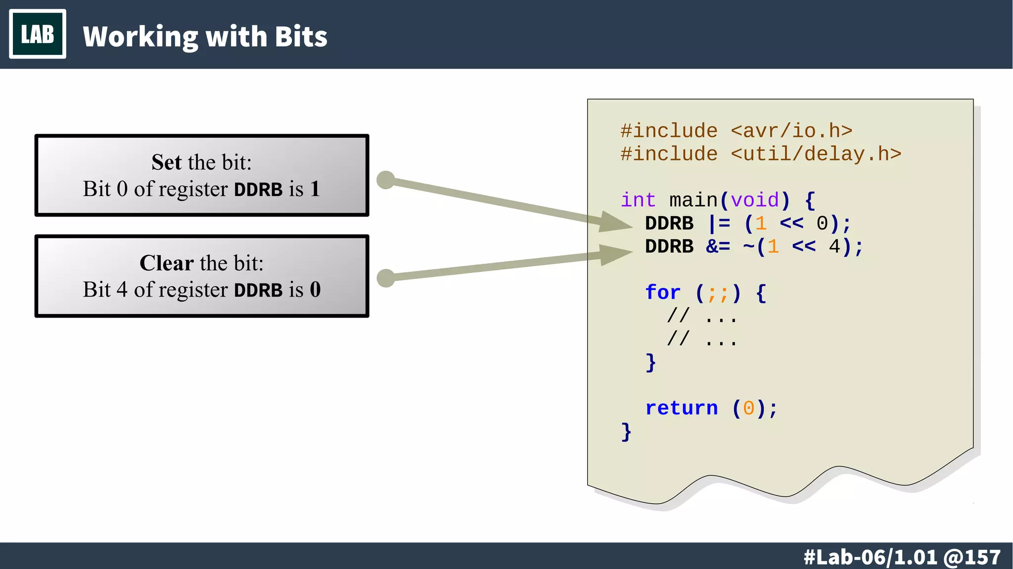
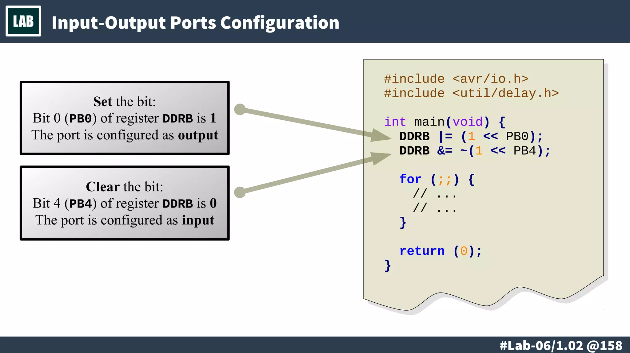
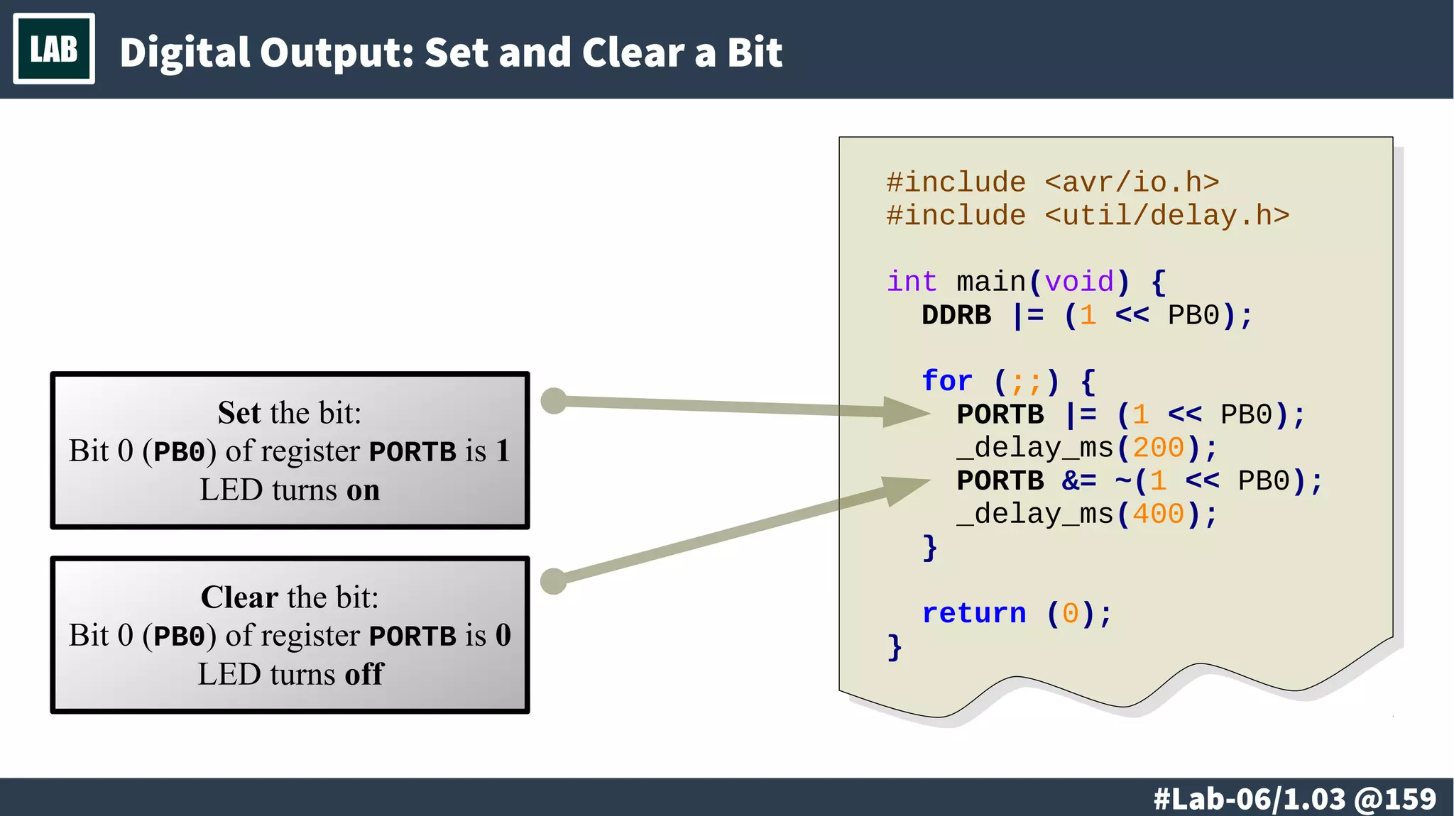

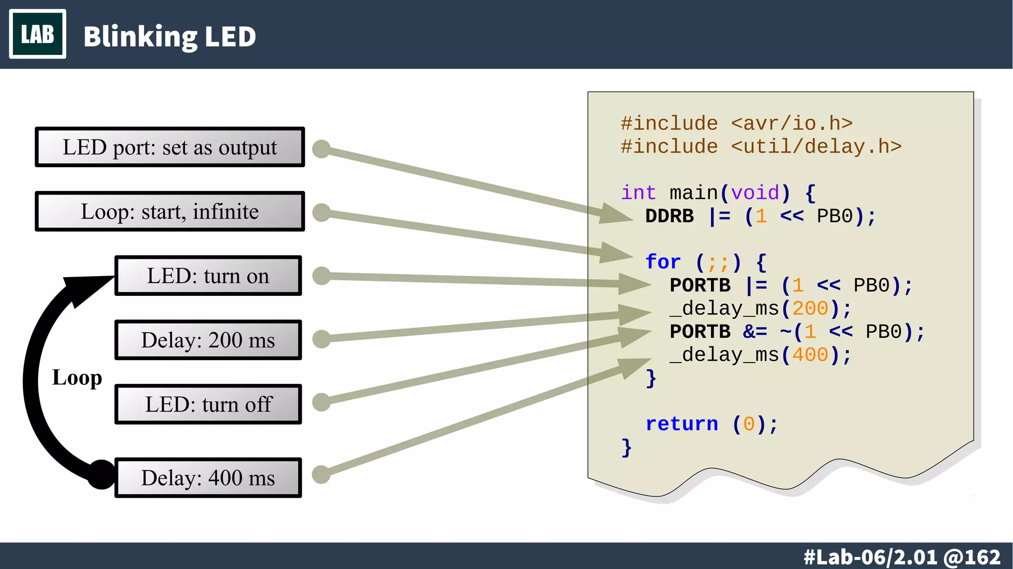
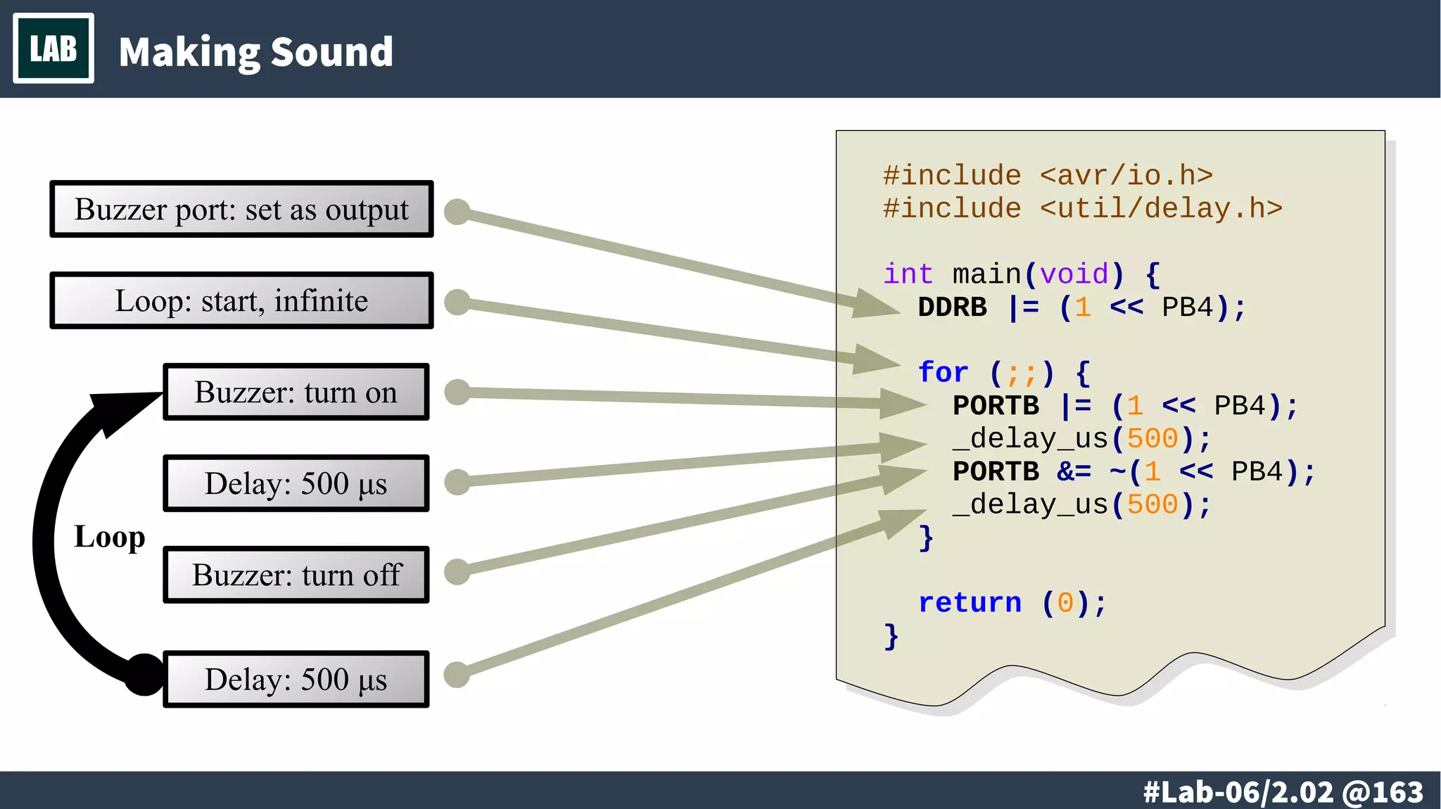
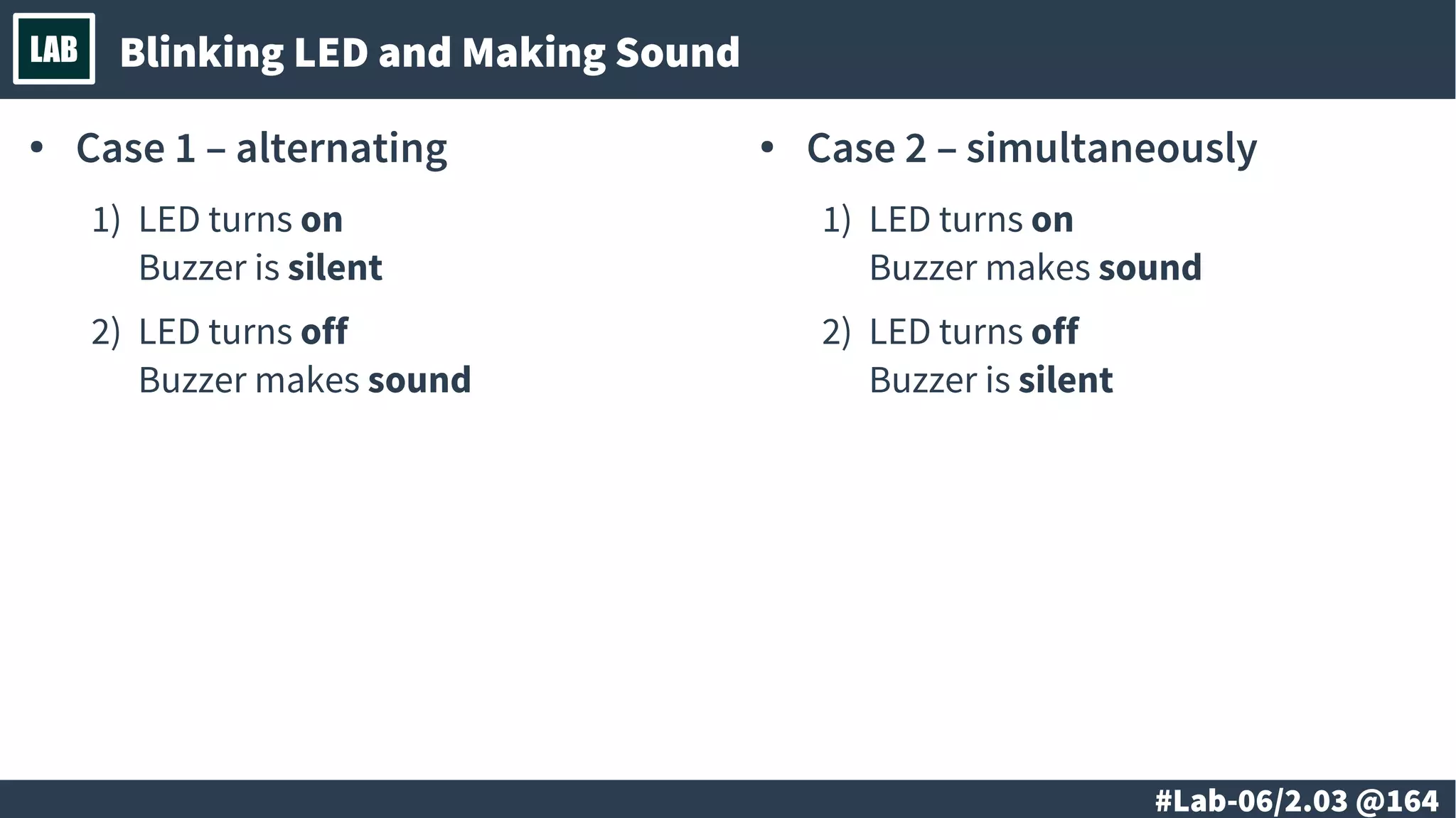


The document discusses microcontrollers and embedded devices, covering their history, functionality, numeral systems, and design principles. It includes details on logical, bitwise, and arithmetic operations, with examples of applications such as digital clocks and robots. The material also presents lab demonstrations for simulating microcontroller systems and practical considerations in designing embedded systems.