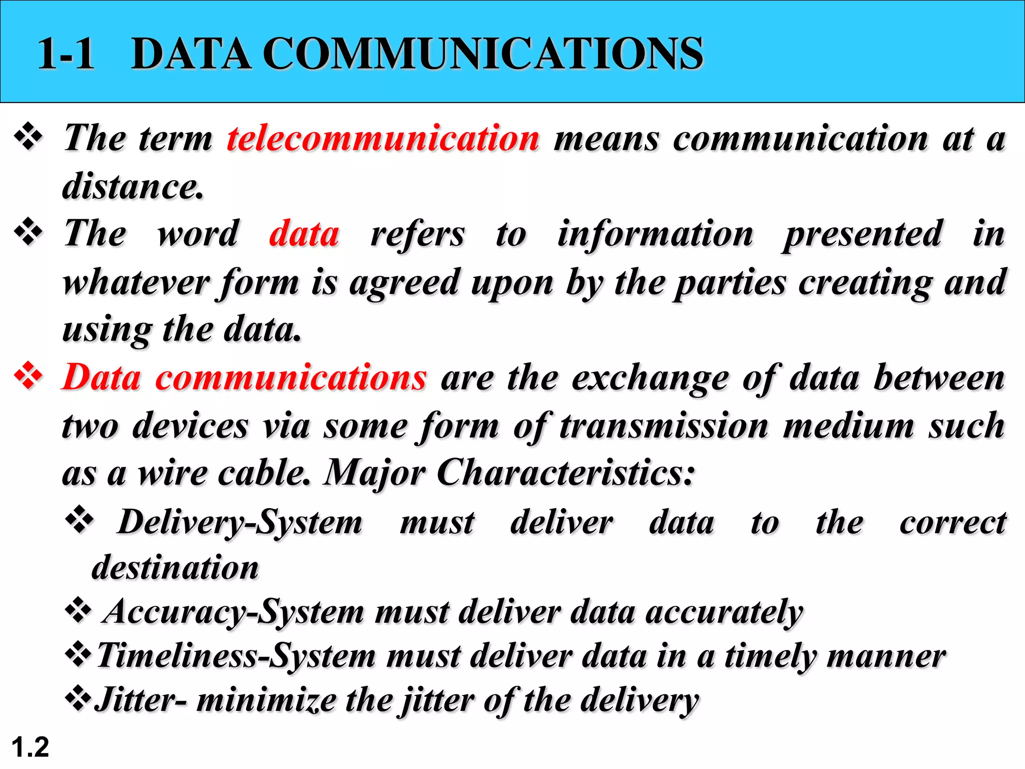
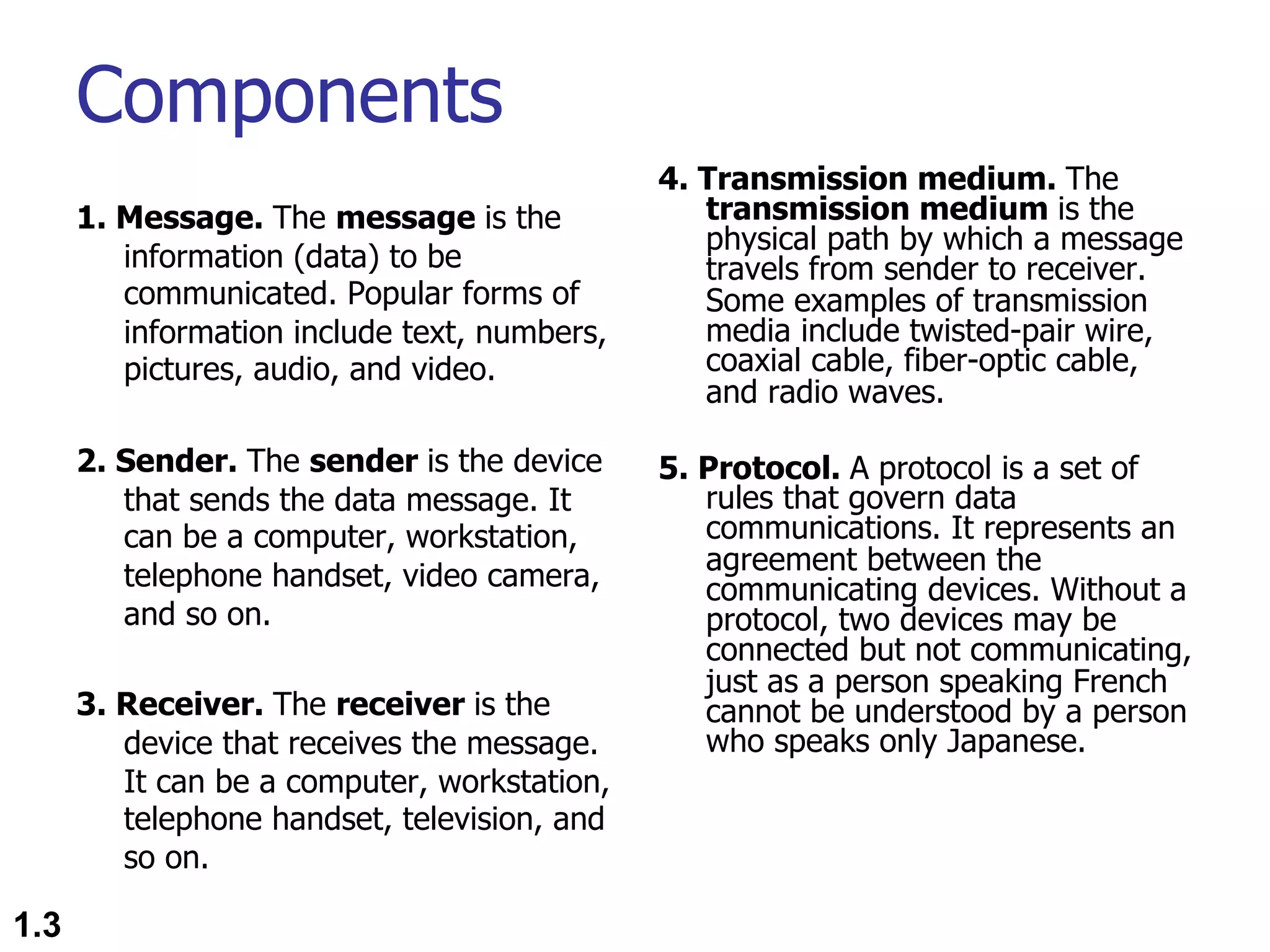
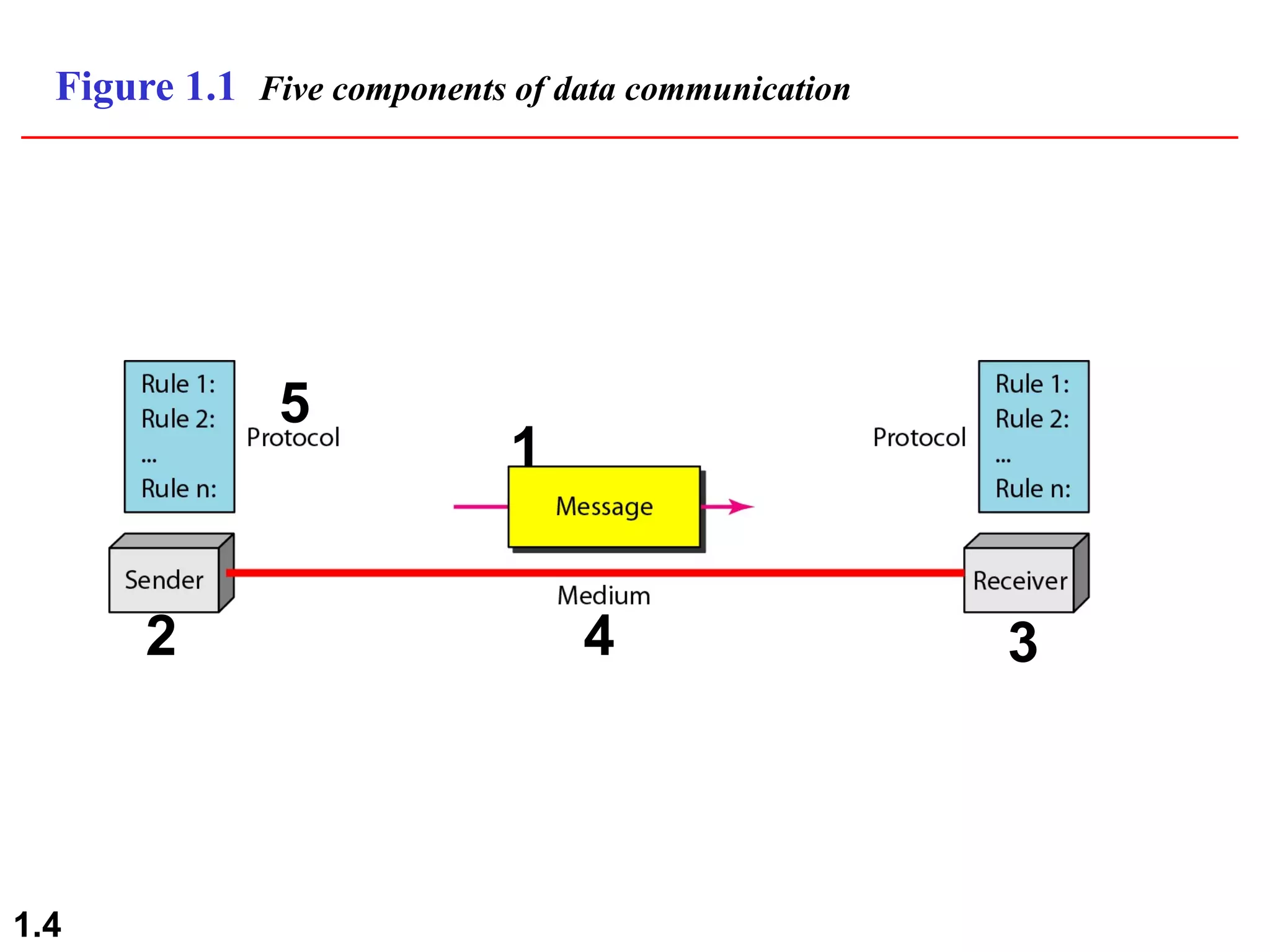
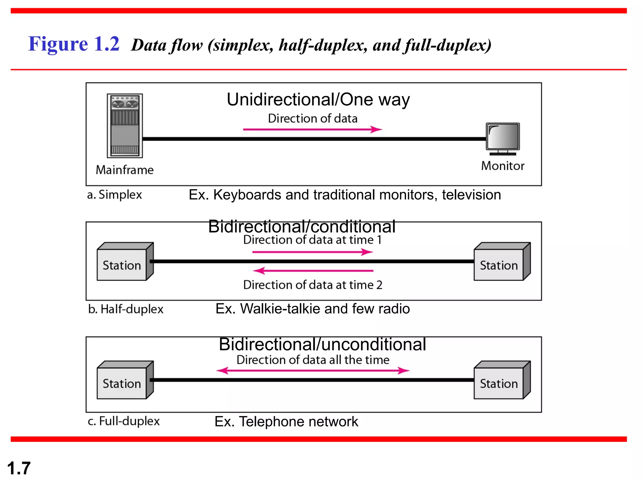
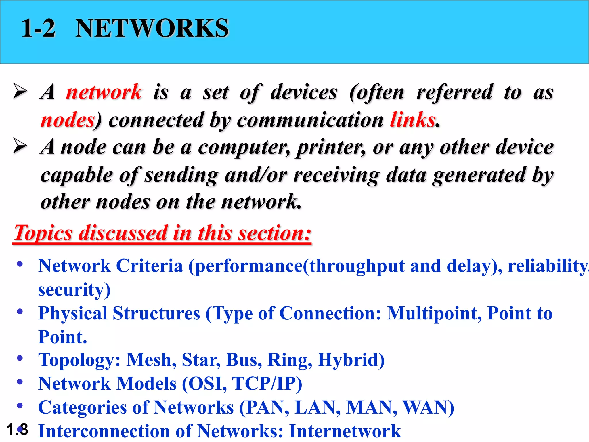
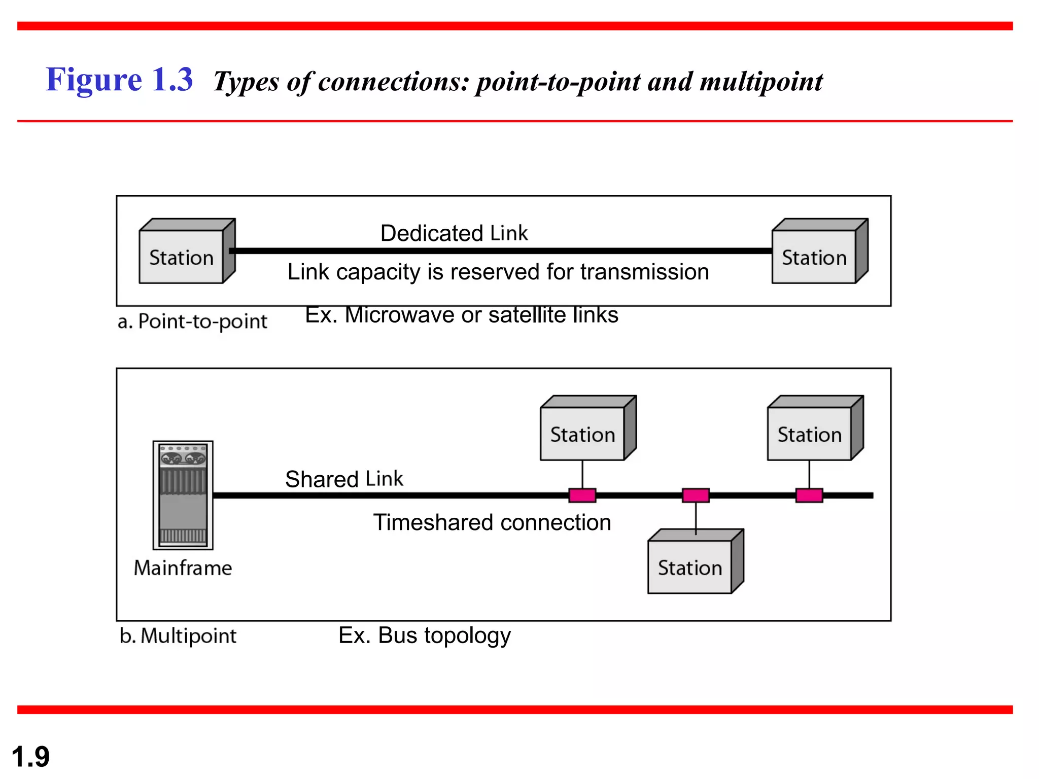
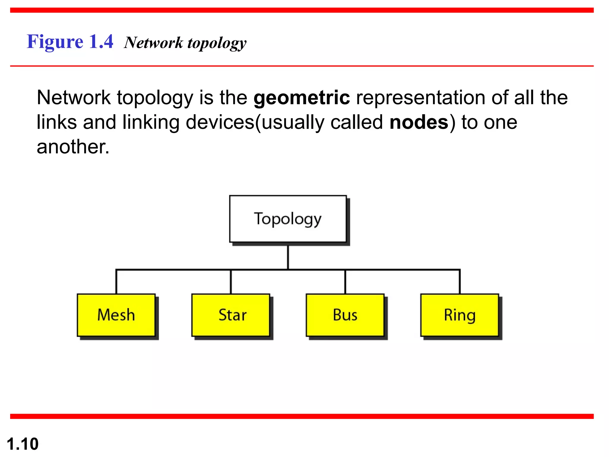
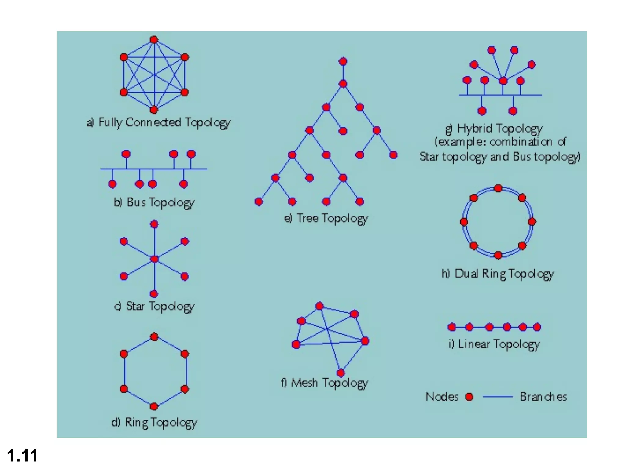
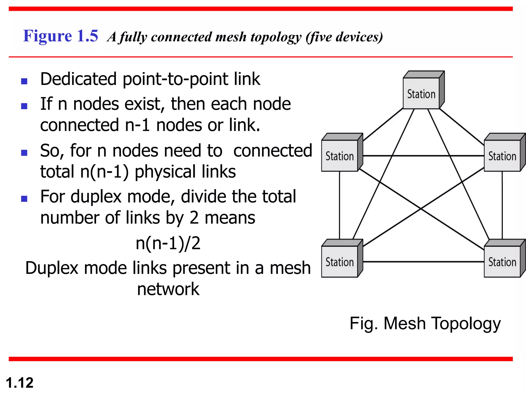
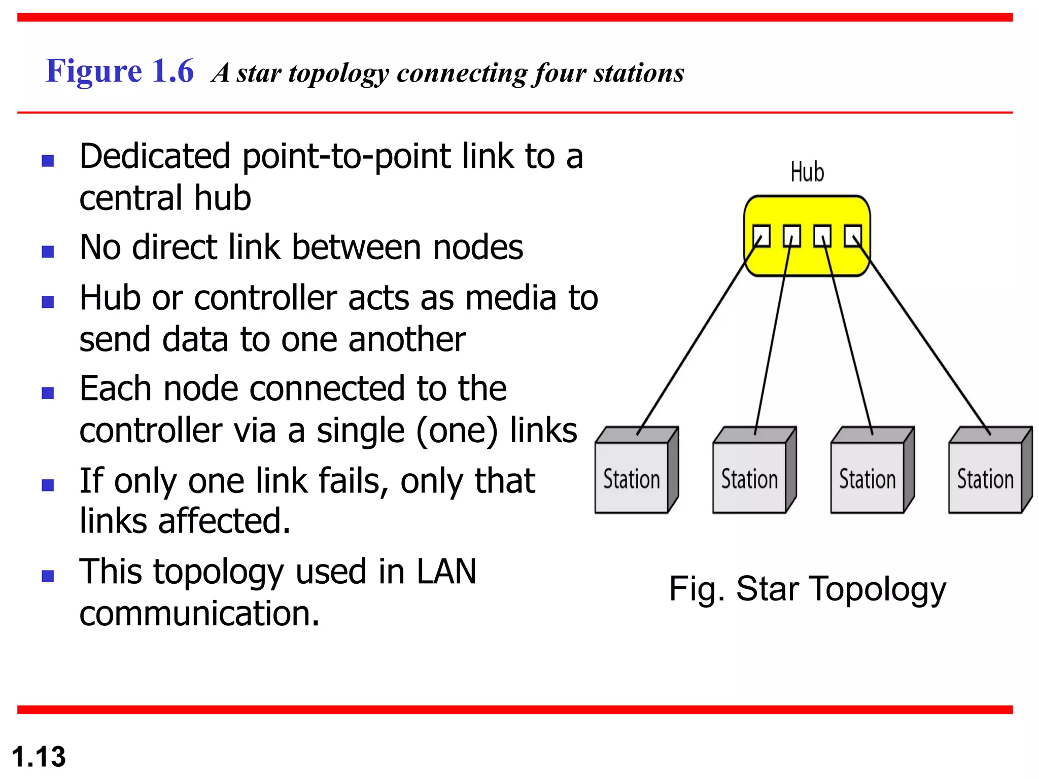
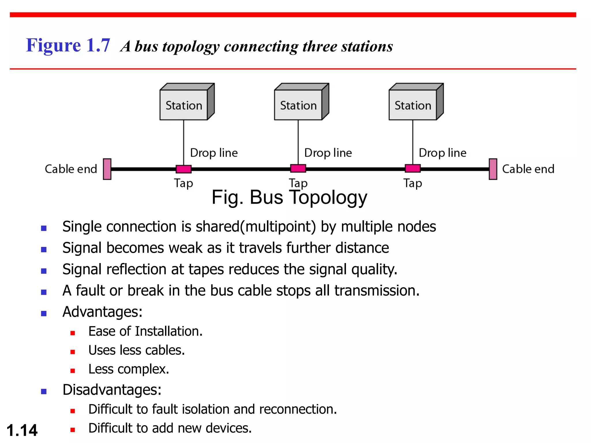
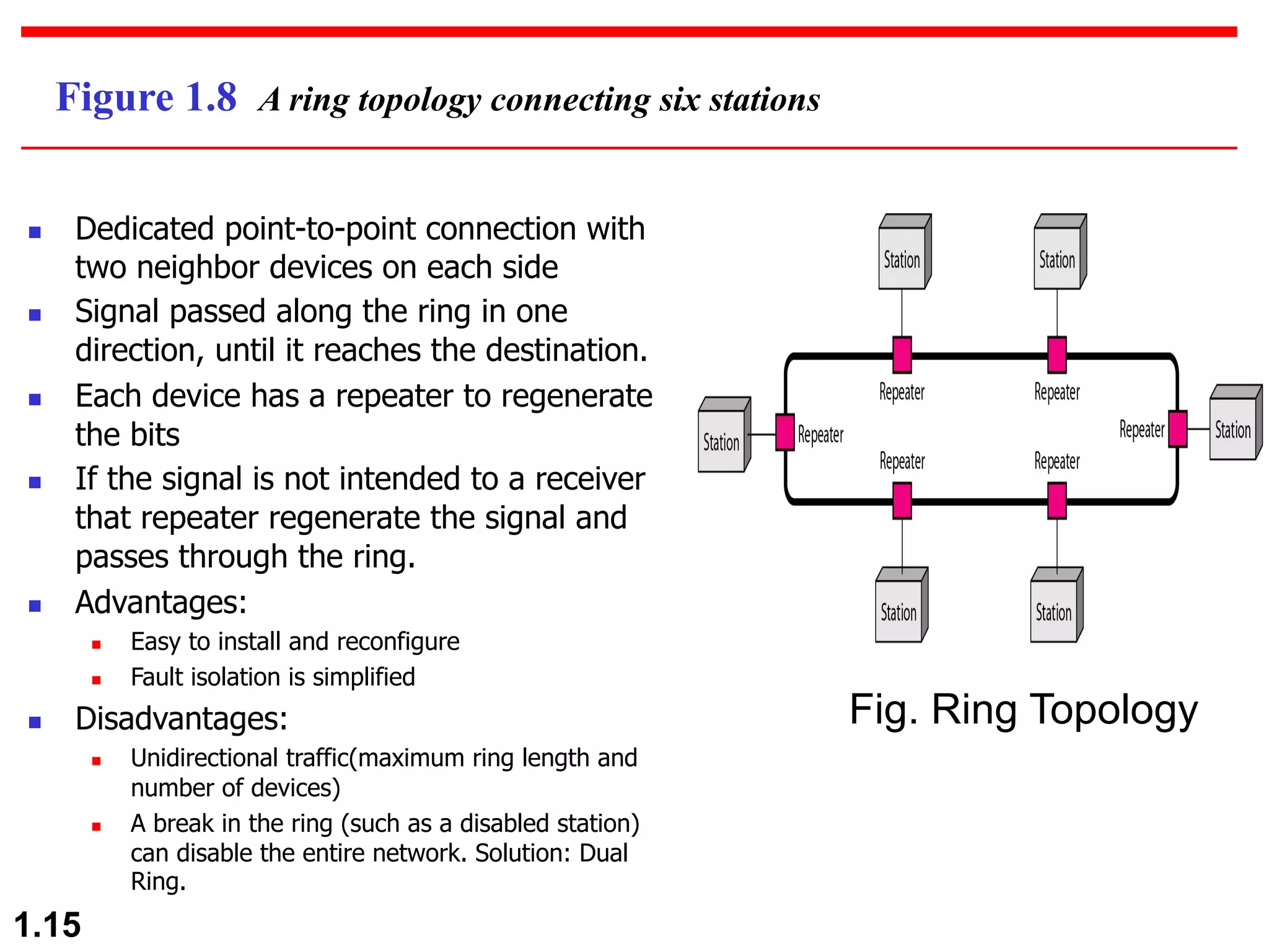
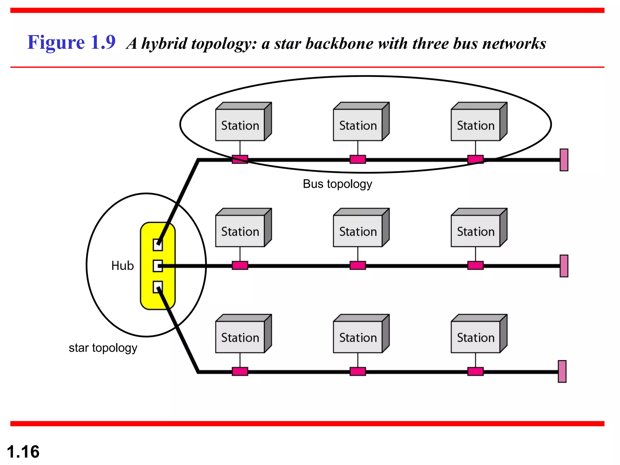
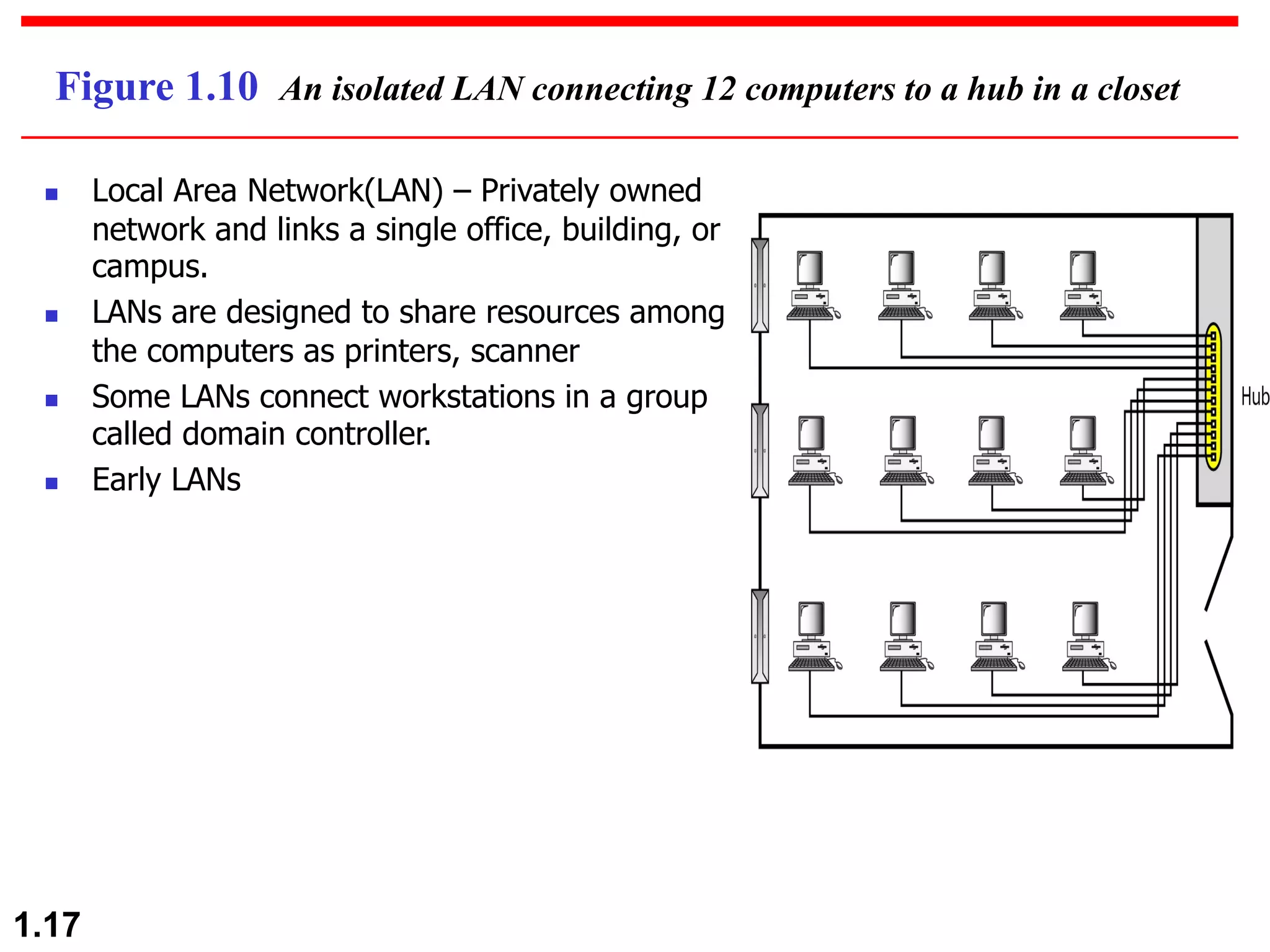
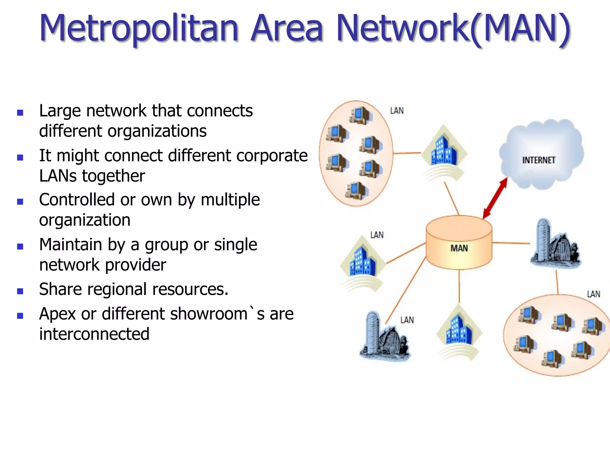
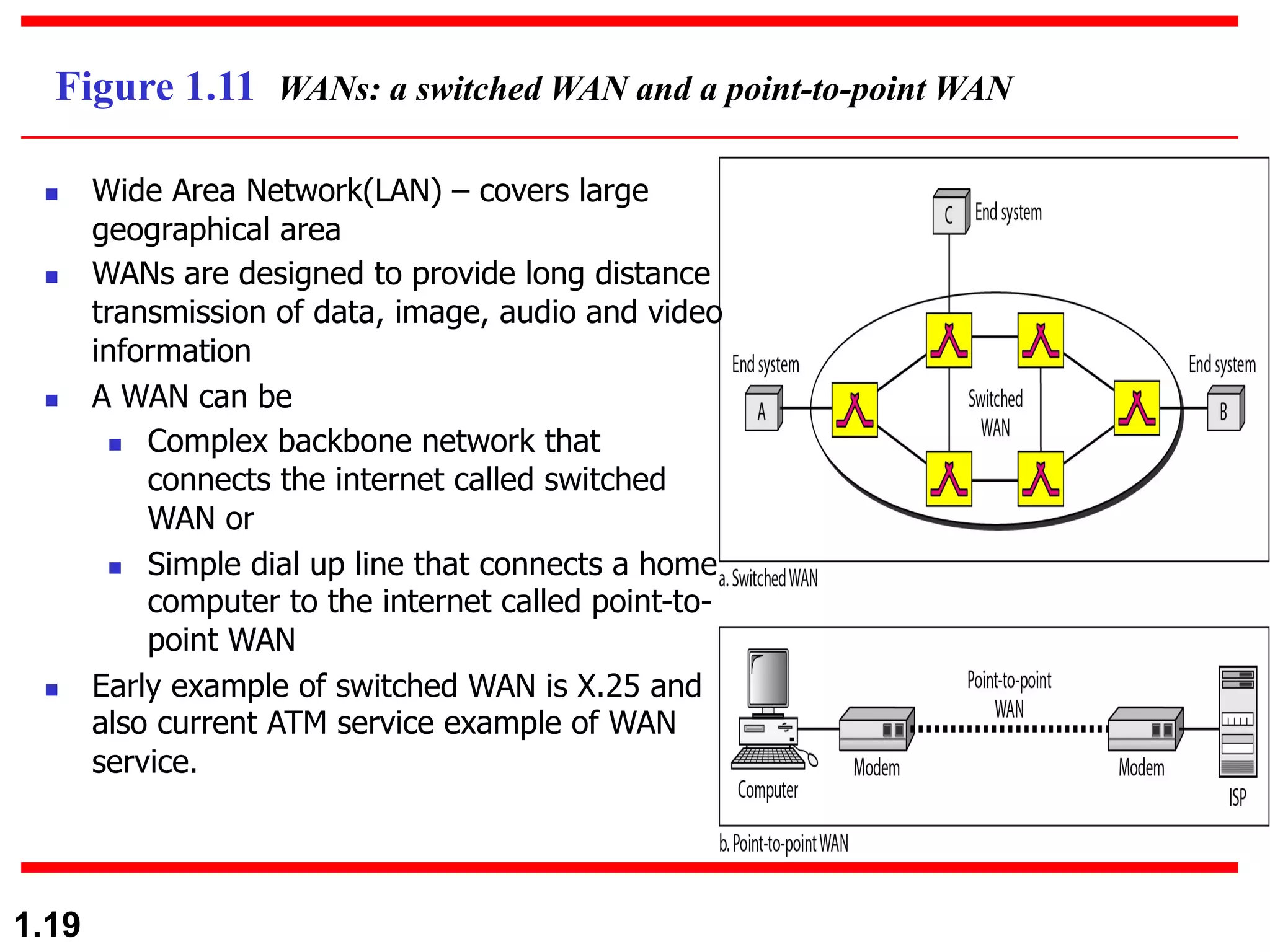
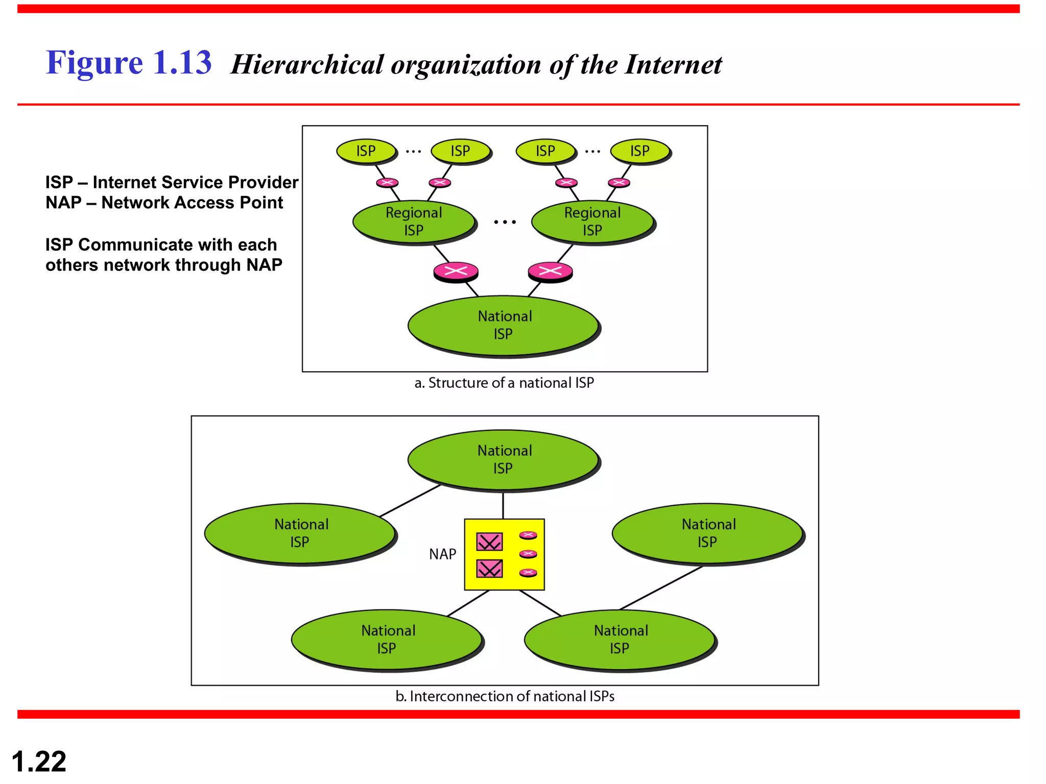
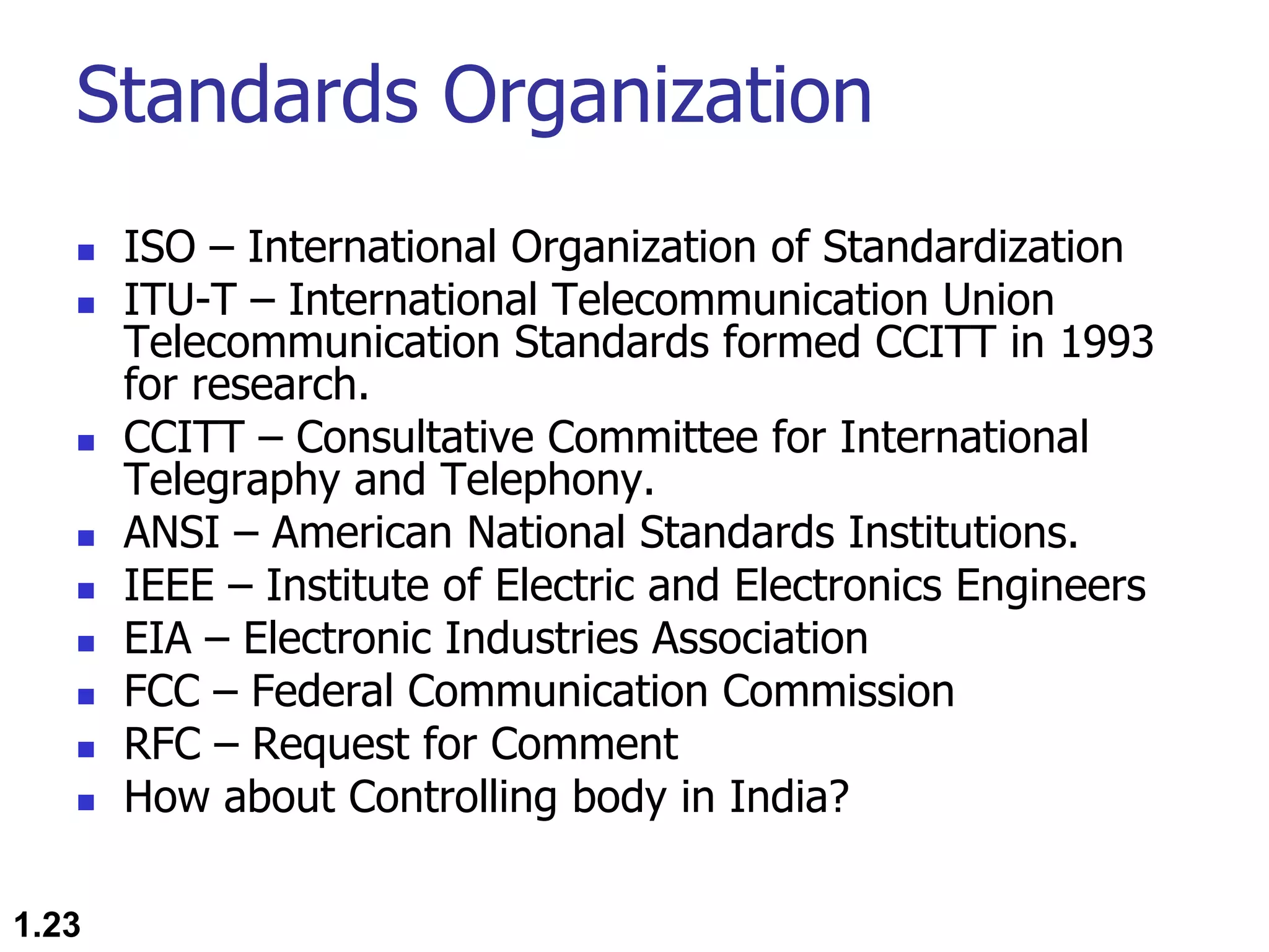
1.1
Chapter 1
Introduction
Copyright © The McGraw-Hill Companies, Inc. Permission required for reproduction or display.
Partially Edited and
Presented by
Dr. Md. Abir Hossain
1.2
1-1 DATA COMMUNICATIONS
v The term telecommunication means communication at a
distance.
v The word data refers to information presented in
whatever form is agreed upon by the parties creating and
using the data.
v Data communications are the exchange of data between
two devices via some form of transmission medium such
as a wire cable. Major Characteristics:
v Delivery-System must deliver data to the correct
destination
v Accuracy-System must deliver data accurately
vTimeliness-System must deliver data in a timely manner
vJitter- minimize the jitter of the delivery
Components
1. Message. The message is the
information (data) to be
communicated. Popular forms of
information include text, numbers,
pictures, audio, and video.
2. Sender. The sender is the device
that sends the data message. It
can be a computer, workstation,
telephone handset, video camera,
and so on.
3. Receiver. The receiver is the
device that receives the message.
It can be a computer, workstation,
telephone handset, television, and
so on.
4. Transmission medium. The
transmission medium is the
physical path by which a message
travels from sender to receiver.
Some examples of transmission
media include twisted-pair wire,
coaxial cable, fiber-optic cable,
and radio waves.
5. Protocol. A protocol is a set of
rules that govern data
communications. It represents an
agreement between the
communicating devices. Without a
protocol, two devices may be
connected but not communicating,
just as a person speaking French
cannot be understood by a person
who speaks only Japanese.
1.3
1.4
Figure 1.1 Five components of data communication
1
2 3
4
5
Data Representation
n Text (Unicode, American Standard Code
for Information Interchange (ASCII))
n Numbers
n Images ( Divided into pixel with size in bit
patterns, has color scheme of RGB- red,
green, and blue or YCM- yellow, cyan, and
magenta.
n Audio
n Video
1.5
Data Flow
n Simplex
n Duplex
n Half Duplex
n Full Duplex
1.6
1.7
Figure 1.2 Data flow (simplex, half-duplex, and full-duplex)
Unidirectional/One way
Ex. Keyboards and traditional monitors, television
Ex. Walkie-talkie and few radio
Ex. Telephone network
Bidirectional/unconditional
Bidirectional/conditional
1.8
1-2 NETWORKS
Ø A network is a set of devices (often referred to as
nodes) connected by communication links.
Ø A node can be a computer, printer, or any other device
capable of sending and/or receiving data generated by
other nodes on the network.
• Network Criteria (performance(throughput and delay), reliability,
security)
• Physical Structures (Type of Connection: Multipoint, Point to
Point.
• Topology: Mesh, Star, Bus, Ring, Hybrid)
• Network Models (OSI, TCP/IP)
• Categories of Networks (PAN, LAN, MAN, WAN)
• Interconnection of Networks: Internetwork
Topics discussed in this section:
1.9
Figure 1.3 Types of connections: point-to-point and multipoint
Dedicated
Link capacity is reserved for transmission
Shared
Ex. Microwave or satellite links
Timeshared connection
Ex. Bus topology
1.10
Figure 1.4 Network topology
Network topology is the geometric representation of all the
links and linking devices(usually called nodes) to one
another.
1.11
1.12
Figure 1.5 A fully connected mesh topology (five devices)
n Dedicated point-to-point link
n If n nodes exist, then each node
connected n-1 nodes or link.
n So, for n nodes need to connected
total n(n-1) physical links
n For duplex mode, divide the total
number of links by 2 means
n(n-1)/2
Duplex mode links present in a mesh
network
Fig. Mesh Topology
1.13
Figure 1.6 A star topology connecting four stations
Fig. Star Topology
n Dedicated point-to-point link to a
central hub
n No direct link between nodes
n Hub or controller acts as media to
send data to one another
n Each node connected to the
controller via a single (one) links
n If only one link fails, only that
links affected.
n This topology used in LAN
communication.
1.14
Figure 1.7 A bus topology connecting three stations
n Single connection is shared(multipoint) by multiple nodes
n Signal becomes weak as it travels further distance
n Signal reflection at tapes reduces the signal quality.
n A fault or break in the bus cable stops all transmission.
n Advantages:
n Ease of Installation.
n Uses less cables.
n Less complex.
n Disadvantages:
n Difficult to fault isolation and reconnection.
n Difficult to add new devices.
Fig. Bus Topology
1.15
Figure 1.8 A ring topology connecting six stations
Fig. Ring Topology
n Dedicated point-to-point connection with
two neighbor devices on each side
n Signal passed along the ring in one
direction, until it reaches the destination.
n Each device has a repeater to regenerate
the bits
n If the signal is not intended to a receiver
that repeater regenerate the signal and
passes through the ring.
n Advantages:
n Easy to install and reconfigure
n Fault isolation is simplified
n Disadvantages:
n Unidirectional traffic(maximum ring length and
number of devices)
n A break in the ring (such as a disabled station)
can disable the entire network. Solution: Dual
Ring.
1.16
Figure 1.9 A hybrid topology: a star backbone with three bus networks
Bus topology
star topology
1.17
Figure 1.10 An isolated LAN connecting 12 computers to a hub in a closet
n Local Area Network(LAN) – Privately owned
network and links a single office, building, or
campus.
n LANs are designed to share resources among
the computers as printers, scanner
n Some LANs connect workstations in a group
called domain controller.
n Early LANs
Metropolitan Area Network(MAN)
n Large network that connects
different organizations
n It might connect different corporate
LANs together
n Controlled or own by multiple
organization
n Maintain by a group or single
network provider
n Share regional resources.
n Apex or different showroom`s are
interconnected
1.19
Figure 1.11 WANs: a switched WAN and a point-to-point WAN
n Wide Area Network(LAN) – covers large
geographical area
n WANs are designed to provide long distance
transmission of data, image, audio and video
information
n A WAN can be
n Complex backbone network that
connects the internet called switched
WAN or
n Simple dial up line that connects a home
computer to the internet called point-to-
point WAN
n Early example of switched WAN is X.25 and
also current ATM service example of WAN
service.
1.20
1-3 THE INTERNET
v The Internet has revolutionized many aspects of our
daily lives.
v It has affected the way we do business as well as the
way we spend our leisure time.
v The Internet is a communication system that has
brought a wealth of information to our fingertips and
organized it for our use.
A Brief History
The Internet Today (ISPs)
Topics discussed in this section:
n Came into existence in 1969 only after Packet Switched Network was invented in 1961 at
MIT by Leonard Kleinrock.
n DoD (Dept of Defense) through ARPA (Advanced Research Projects Agency) represented
ARPANET in ACM (Association of Comuting Machinery) meeting in 1967.
n Introduced IMP (Interface Message Processor).
n In 1969, UCLA – UCSB – SRI – UoU got connected.
n University of California Los Angeles – UCLA
n University of California Santa Barbara – UCSB
n University of Utah – UoU
n Sanford Research Institute (SRI)
n Software Support by NCP – Network Control Protocol.
n 1972, Vint Cerf and Bob Kahn came up with paper on TCP with networking concepts of
encapsulation, datagram, gateways, end to end delivery of packets.
n Soon TCP was split into TCP and IP.
n In 1981, UC Berkeley modified the UNIX operating system to include TCP/IP which
popularized Internetworking.
n Then came creation of CSNET in 1981. Computer Science Network (CSNET) was a
network sponsored by the National Science Foundation (NSF).
n In 1983, ARPANET split into two networks: Military Network (MILNET) for military
users and ARPANET for nonmilitary users.
n Today, it is managed by ISP – Internet Service Providers.
1.21
Brief History
1.22
Figure 1.13 Hierarchical organization of the Internet
ISP – Internet Service Provider
NAP – Network Access Point
ISP Communicate with each
others network through NAP
Standards Organization
n ISO – International Organization of Standardization
n ITU-T – International Telecommunication Union
Telecommunication Standards formed CCITT in 1993
for research.
n CCITT – Consultative Committee for International
Telegraphy and Telephony.
n ANSI – American National Standards Institutions.
n IEEE – Institute of Electric and Electronics Engineers
n EIA – Electronic Industries Association
n FCC – Federal Communication Commission
n RFC – Request for Comment
n How about Controlling body in India?
1.23
1.24

Introduction to Computer Networking

  • 1.
    1.1 Chapter 1 Introduction Copyright ©The McGraw-Hill Companies, Inc. Permission required for reproduction or display. Partially Edited and Presented by Dr. Md. Abir Hossain
  • 2.
    1.2 1-1 DATA COMMUNICATIONS vThe term telecommunication means communication at a distance. v The word data refers to information presented in whatever form is agreed upon by the parties creating and using the data. v Data communications are the exchange of data between two devices via some form of transmission medium such as a wire cable. Major Characteristics: v Delivery-System must deliver data to the correct destination v Accuracy-System must deliver data accurately vTimeliness-System must deliver data in a timely manner vJitter- minimize the jitter of the delivery
  • 3.
    Components 1. Message. Themessage is the information (data) to be communicated. Popular forms of information include text, numbers, pictures, audio, and video. 2. Sender. The sender is the device that sends the data message. It can be a computer, workstation, telephone handset, video camera, and so on. 3. Receiver. The receiver is the device that receives the message. It can be a computer, workstation, telephone handset, television, and so on. 4. Transmission medium. The transmission medium is the physical path by which a message travels from sender to receiver. Some examples of transmission media include twisted-pair wire, coaxial cable, fiber-optic cable, and radio waves. 5. Protocol. A protocol is a set of rules that govern data communications. It represents an agreement between the communicating devices. Without a protocol, two devices may be connected but not communicating, just as a person speaking French cannot be understood by a person who speaks only Japanese. 1.3
  • 4.
    1.4 Figure 1.1 Fivecomponents of data communication 1 2 3 4 5
  • 5.
    Data Representation n Text(Unicode, American Standard Code for Information Interchange (ASCII)) n Numbers n Images ( Divided into pixel with size in bit patterns, has color scheme of RGB- red, green, and blue or YCM- yellow, cyan, and magenta. n Audio n Video 1.5
  • 6.
    Data Flow n Simplex nDuplex n Half Duplex n Full Duplex 1.6
  • 7.
    1.7 Figure 1.2 Dataflow (simplex, half-duplex, and full-duplex) Unidirectional/One way Ex. Keyboards and traditional monitors, television Ex. Walkie-talkie and few radio Ex. Telephone network Bidirectional/unconditional Bidirectional/conditional
  • 8.
    1.8 1-2 NETWORKS Ø Anetwork is a set of devices (often referred to as nodes) connected by communication links. Ø A node can be a computer, printer, or any other device capable of sending and/or receiving data generated by other nodes on the network. • Network Criteria (performance(throughput and delay), reliability, security) • Physical Structures (Type of Connection: Multipoint, Point to Point. • Topology: Mesh, Star, Bus, Ring, Hybrid) • Network Models (OSI, TCP/IP) • Categories of Networks (PAN, LAN, MAN, WAN) • Interconnection of Networks: Internetwork Topics discussed in this section:
  • 9.
    1.9 Figure 1.3 Typesof connections: point-to-point and multipoint Dedicated Link capacity is reserved for transmission Shared Ex. Microwave or satellite links Timeshared connection Ex. Bus topology
  • 10.
    1.10 Figure 1.4 Networktopology Network topology is the geometric representation of all the links and linking devices(usually called nodes) to one another.
  • 11.
  • 12.
    1.12 Figure 1.5 Afully connected mesh topology (five devices) n Dedicated point-to-point link n If n nodes exist, then each node connected n-1 nodes or link. n So, for n nodes need to connected total n(n-1) physical links n For duplex mode, divide the total number of links by 2 means n(n-1)/2 Duplex mode links present in a mesh network Fig. Mesh Topology
  • 13.
    1.13 Figure 1.6 Astar topology connecting four stations Fig. Star Topology n Dedicated point-to-point link to a central hub n No direct link between nodes n Hub or controller acts as media to send data to one another n Each node connected to the controller via a single (one) links n If only one link fails, only that links affected. n This topology used in LAN communication.
  • 14.
    1.14 Figure 1.7 Abus topology connecting three stations n Single connection is shared(multipoint) by multiple nodes n Signal becomes weak as it travels further distance n Signal reflection at tapes reduces the signal quality. n A fault or break in the bus cable stops all transmission. n Advantages: n Ease of Installation. n Uses less cables. n Less complex. n Disadvantages: n Difficult to fault isolation and reconnection. n Difficult to add new devices. Fig. Bus Topology
  • 15.
    1.15 Figure 1.8 Aring topology connecting six stations Fig. Ring Topology n Dedicated point-to-point connection with two neighbor devices on each side n Signal passed along the ring in one direction, until it reaches the destination. n Each device has a repeater to regenerate the bits n If the signal is not intended to a receiver that repeater regenerate the signal and passes through the ring. n Advantages: n Easy to install and reconfigure n Fault isolation is simplified n Disadvantages: n Unidirectional traffic(maximum ring length and number of devices) n A break in the ring (such as a disabled station) can disable the entire network. Solution: Dual Ring.
  • 16.
    1.16 Figure 1.9 Ahybrid topology: a star backbone with three bus networks Bus topology star topology
  • 17.
    1.17 Figure 1.10 Anisolated LAN connecting 12 computers to a hub in a closet n Local Area Network(LAN) – Privately owned network and links a single office, building, or campus. n LANs are designed to share resources among the computers as printers, scanner n Some LANs connect workstations in a group called domain controller. n Early LANs
  • 18.
    Metropolitan Area Network(MAN) nLarge network that connects different organizations n It might connect different corporate LANs together n Controlled or own by multiple organization n Maintain by a group or single network provider n Share regional resources. n Apex or different showroom`s are interconnected
  • 19.
    1.19 Figure 1.11 WANs:a switched WAN and a point-to-point WAN n Wide Area Network(LAN) – covers large geographical area n WANs are designed to provide long distance transmission of data, image, audio and video information n A WAN can be n Complex backbone network that connects the internet called switched WAN or n Simple dial up line that connects a home computer to the internet called point-to- point WAN n Early example of switched WAN is X.25 and also current ATM service example of WAN service.
  • 20.
    1.20 1-3 THE INTERNET vThe Internet has revolutionized many aspects of our daily lives. v It has affected the way we do business as well as the way we spend our leisure time. v The Internet is a communication system that has brought a wealth of information to our fingertips and organized it for our use. A Brief History The Internet Today (ISPs) Topics discussed in this section:
  • 21.
    n Came intoexistence in 1969 only after Packet Switched Network was invented in 1961 at MIT by Leonard Kleinrock. n DoD (Dept of Defense) through ARPA (Advanced Research Projects Agency) represented ARPANET in ACM (Association of Comuting Machinery) meeting in 1967. n Introduced IMP (Interface Message Processor). n In 1969, UCLA – UCSB – SRI – UoU got connected. n University of California Los Angeles – UCLA n University of California Santa Barbara – UCSB n University of Utah – UoU n Sanford Research Institute (SRI) n Software Support by NCP – Network Control Protocol. n 1972, Vint Cerf and Bob Kahn came up with paper on TCP with networking concepts of encapsulation, datagram, gateways, end to end delivery of packets. n Soon TCP was split into TCP and IP. n In 1981, UC Berkeley modified the UNIX operating system to include TCP/IP which popularized Internetworking. n Then came creation of CSNET in 1981. Computer Science Network (CSNET) was a network sponsored by the National Science Foundation (NSF). n In 1983, ARPANET split into two networks: Military Network (MILNET) for military users and ARPANET for nonmilitary users. n Today, it is managed by ISP – Internet Service Providers. 1.21 Brief History
  • 22.
    1.22 Figure 1.13 Hierarchicalorganization of the Internet ISP – Internet Service Provider NAP – Network Access Point ISP Communicate with each others network through NAP
  • 23.
    Standards Organization n ISO– International Organization of Standardization n ITU-T – International Telecommunication Union Telecommunication Standards formed CCITT in 1993 for research. n CCITT – Consultative Committee for International Telegraphy and Telephony. n ANSI – American National Standards Institutions. n IEEE – Institute of Electric and Electronics Engineers n EIA – Electronic Industries Association n FCC – Federal Communication Commission n RFC – Request for Comment n How about Controlling body in India? 1.23
  • 24.