Downloaded 193 times
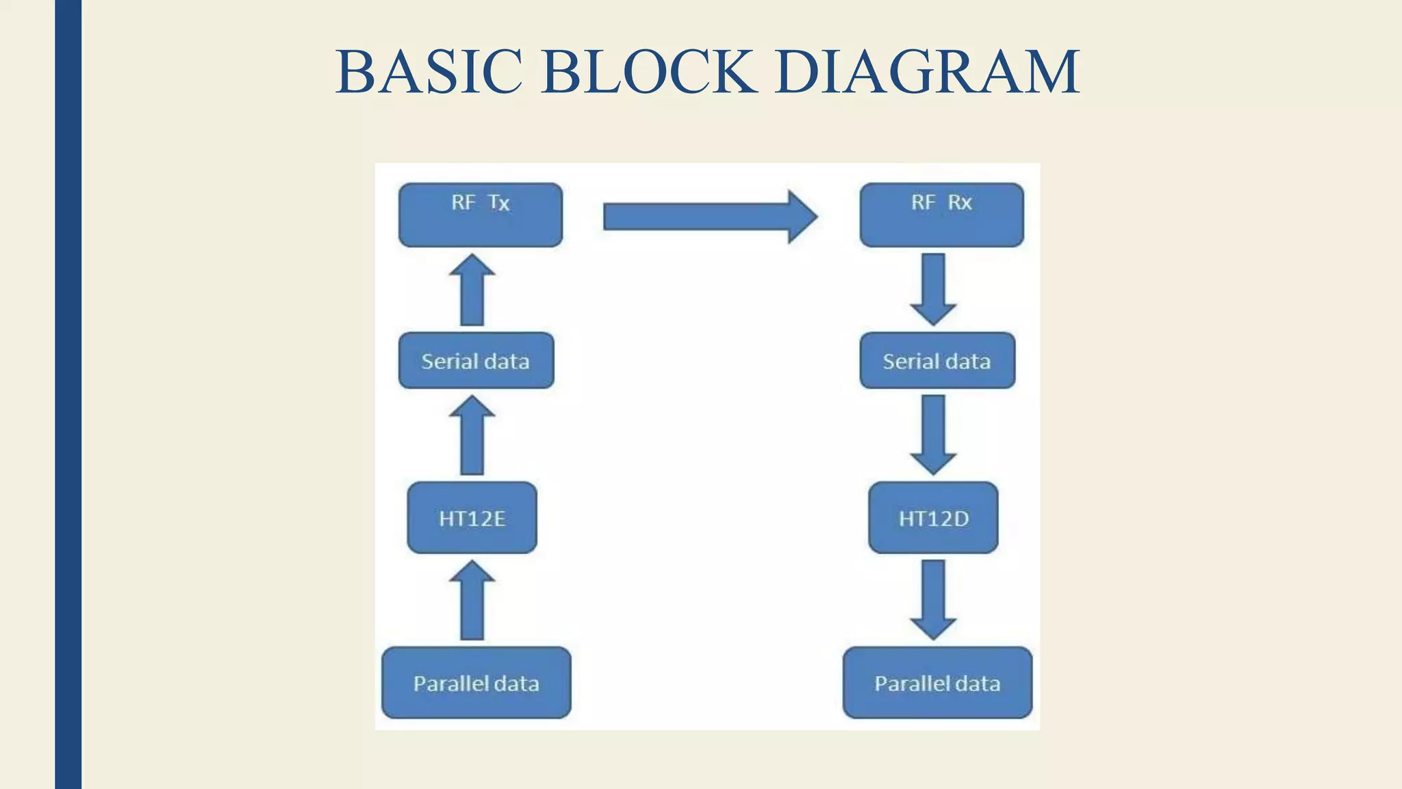
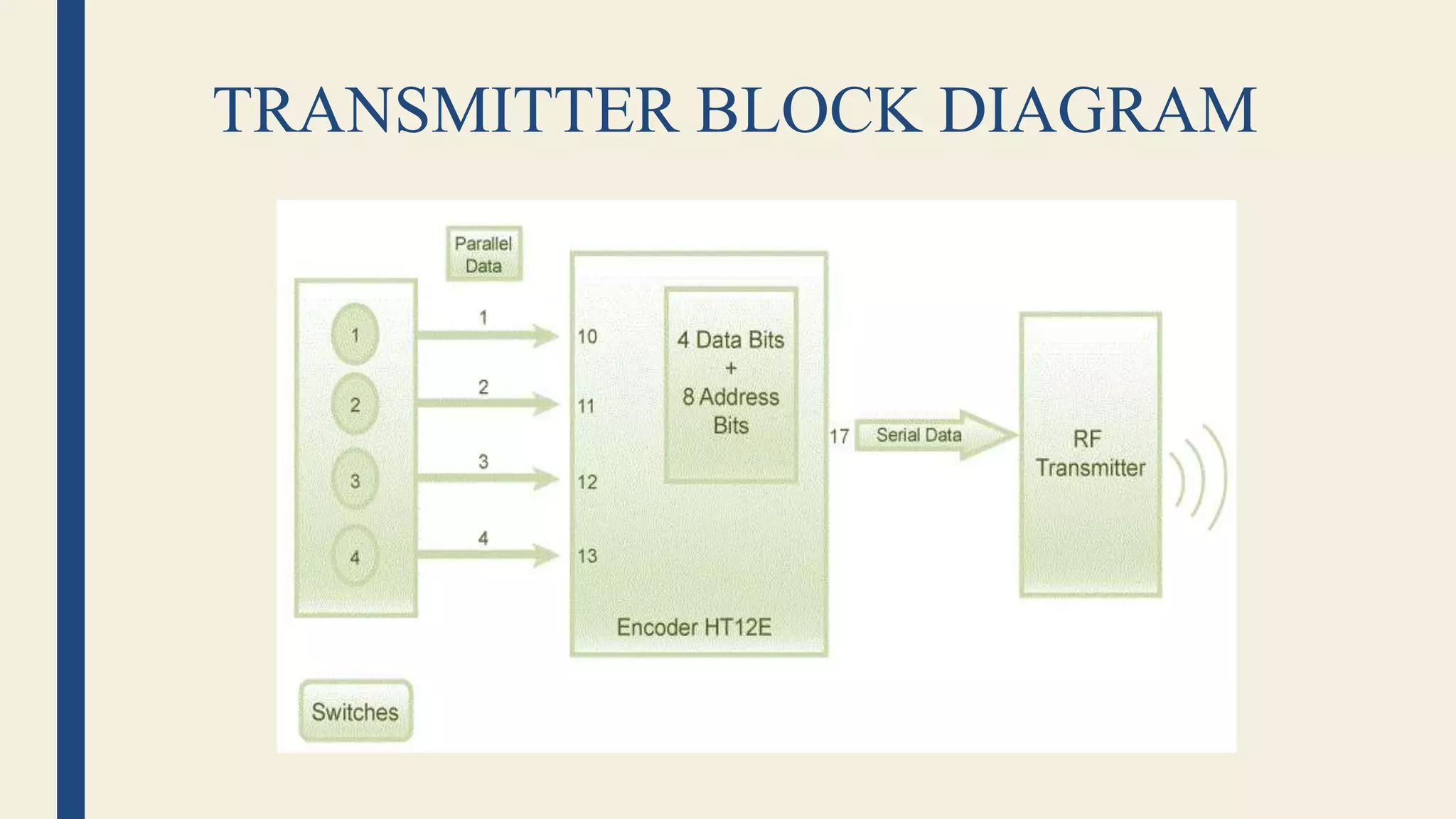
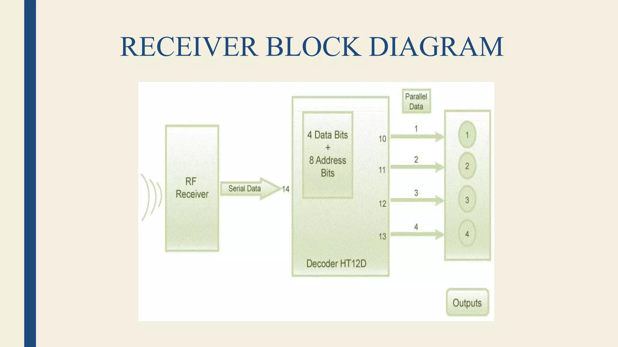
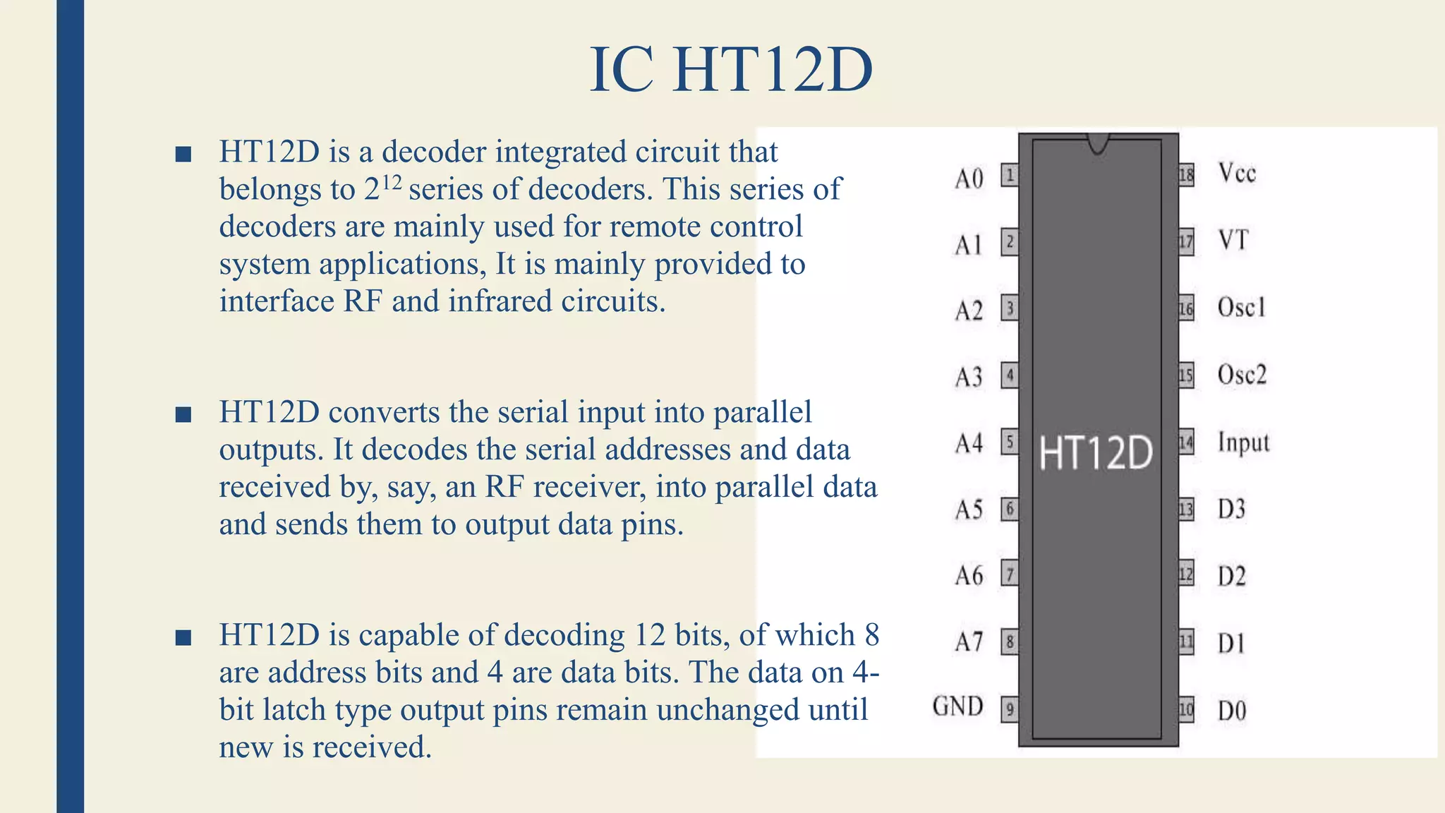
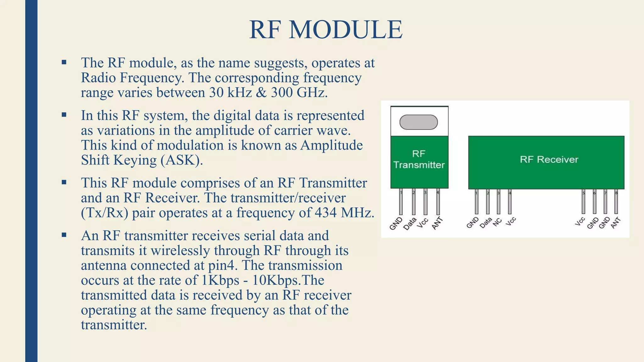
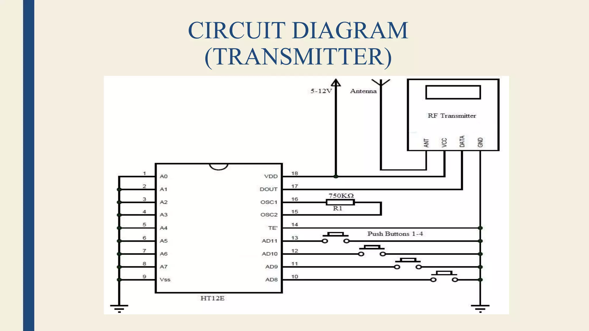
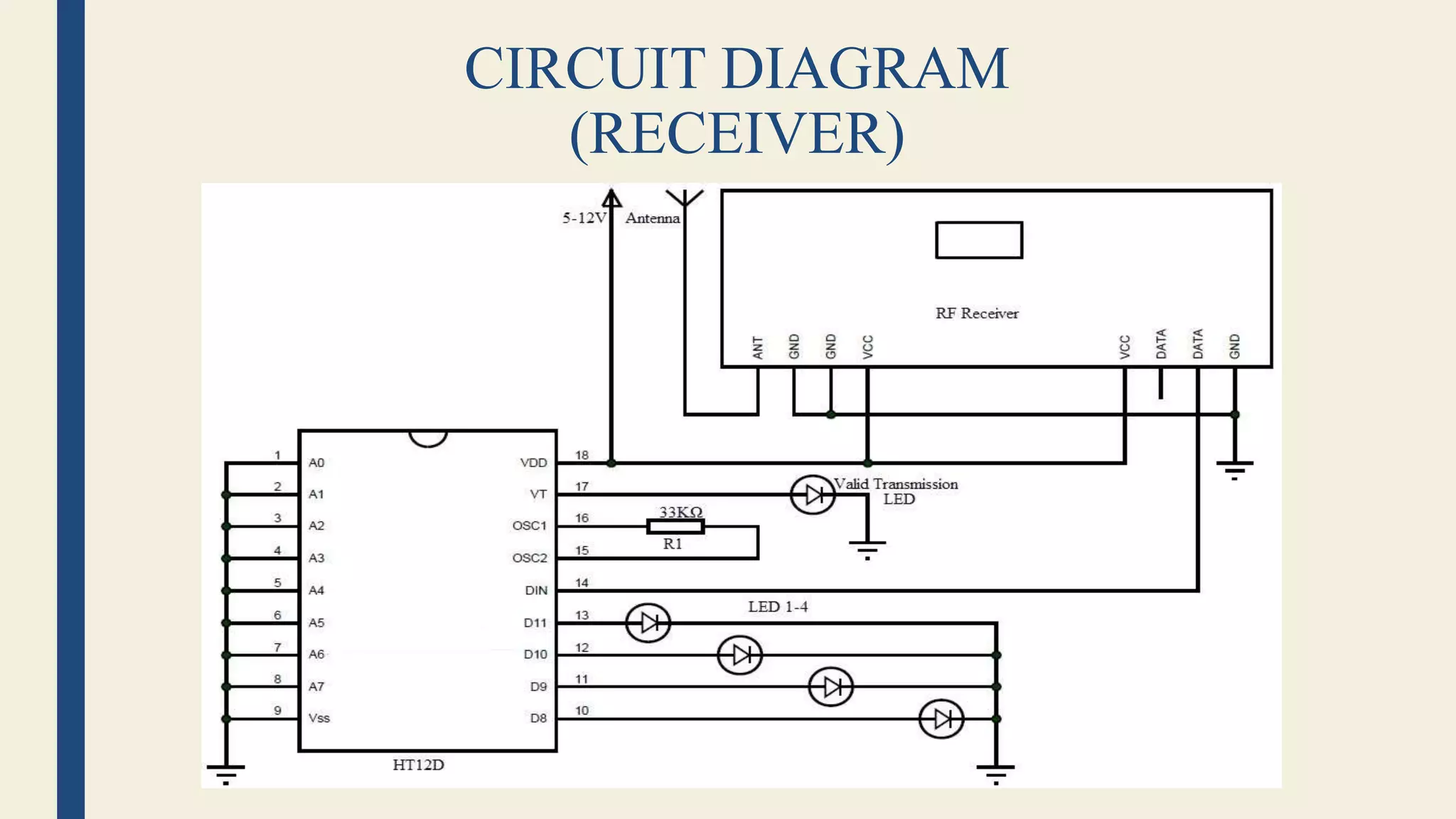


This document describes a home automation system using radio frequency (RF) communication. It consists of a transmitter section and receiver section that communicate wirelessly. The transmitter section contains an HT12E encoder IC and ASK transmitter that encode button presses into a serial RF signal. The receiver section contains an HT12D decoder IC and ASK receiver that receive the RF signal, decode it into parallel data, and control connected loads like lights and appliances. The system allows wireless control of home devices from a distance of up to 20 meters and finds applications in home automation and remote control systems.