System modeling
Systemmodeling is the process of developing abstract
models of a system, with each model presenting a
different view or perspective of that system.
System modeling has now come to mean representing a
system using some kind of graphical notation, which is
now almost always based on notations in the Unified
Modeling Language (UML).
System modelling helps the analyst to understand the
functionality of the system and models are used to
communicate with customers.
3
Chapter 5 System modeling
4.
Existing and plannedsystem models
Models of the existing system are used during requirements
engineering. They help clarify what the existing system does
and can be used as a basis for discussing its strengths and
weaknesses. These then lead to requirements for the new
system.
Models of the new system are used during requirements
engineering to help explain the proposed requirements to
other system stakeholders. Engineers use these models to
discuss design proposals and to document the system for
implementation.
In a model-driven engineering process, it is possible to
generate a complete or partial system implementation from
the system model.
4
Chapter 5 System modeling
5.
System perspectives
Anexternal perspective, where you model the context or
environment of the system.
An interaction perspective, where you model the
interactions between a system and its environment, or
between the components of a system.
A structural perspective, where you model the
organization of a system or the structure of the data that
is processed by the system.
A behavioral perspective, where you model the dynamic
behavior of the system and how it responds to events.
5
Chapter 5 System modeling
6.
UML diagram types
Activity diagrams, which show the activities involved in a
process or in data processing .
Use case diagrams, which show the interactions
between a system and its environment.
Sequence diagrams, which show interactions between
actors and the system and between system components.
Class diagrams, which show the object classes in the
system and the associations between these classes.
State diagrams, which show how the system reacts to
internal and external events.
6
Chapter 5 System modeling
7.
Use of graphicalmodels
As a means of facilitating discussion about an existing or
proposed system
Incomplete and incorrect models are OK as their role is to
support discussion.
As a way of documenting an existing system
Models should be an accurate representation of the system but
need not be complete.
As a detailed system description that can be used to
generate a system implementation
Models have to be both correct and complete.
7
Chapter 5 System modeling
Interaction models
Modelinguser interaction is important as it helps to
identify user requirements.
Modeling system-to-system interaction highlights the
communication problems that may arise.
Modeling component interaction helps us understand if a
proposed system structure is likely to deliver the required
system performance and dependability.
Use case diagrams and sequence diagrams may be
used for interaction modeling.
9
Chapter 5 System modeling
10.
Use case modeling
Use cases were developed originally to support
requirements elicitation and now incorporated into the
UML.
Each use case represents a discrete task that involves
external interaction with a system.
Actors in a use case may be people or other systems.
Represented diagramatically to provide an overview of
the use case and in a more detailed textual form.
10
Chapter 5 System modeling
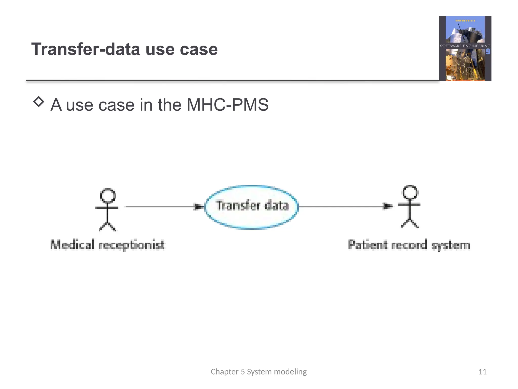
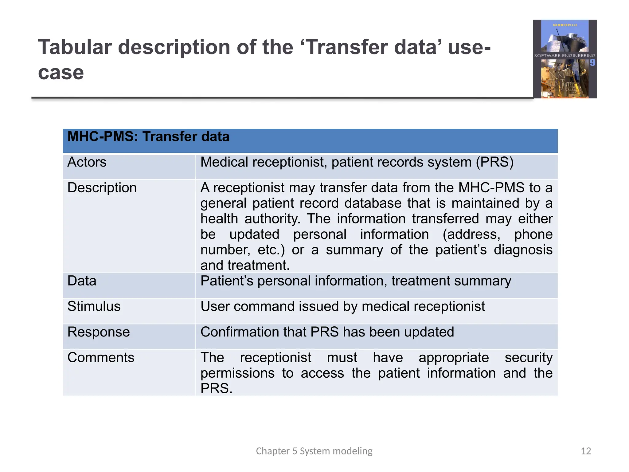
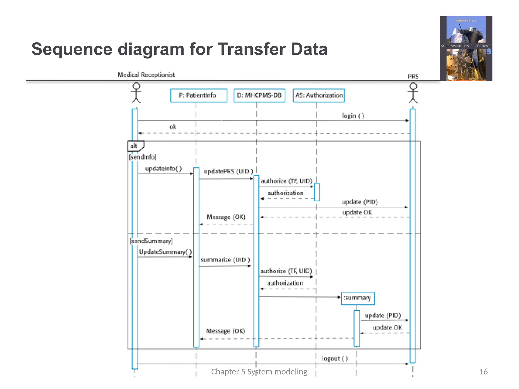
Tabular description ofthe ‘Transfer data’ use-
case
MHC-PMS: Transfer data
Actors Medical receptionist, patient records system (PRS)
Description A receptionist may transfer data from the MHC-PMS to a
general patient record database that is maintained by a
health authority. The information transferred may either
be updated personal information (address, phone
number, etc.) or a summary of the patient’s diagnosis
and treatment.
Data Patient’s personal information, treatment summary
Stimulus User command issued by medical receptionist
Response Confirmation that PRS has been updated
Comments The receptionist must have appropriate security
permissions to access the patient information and the
PRS.
12
Chapter 5 System modeling
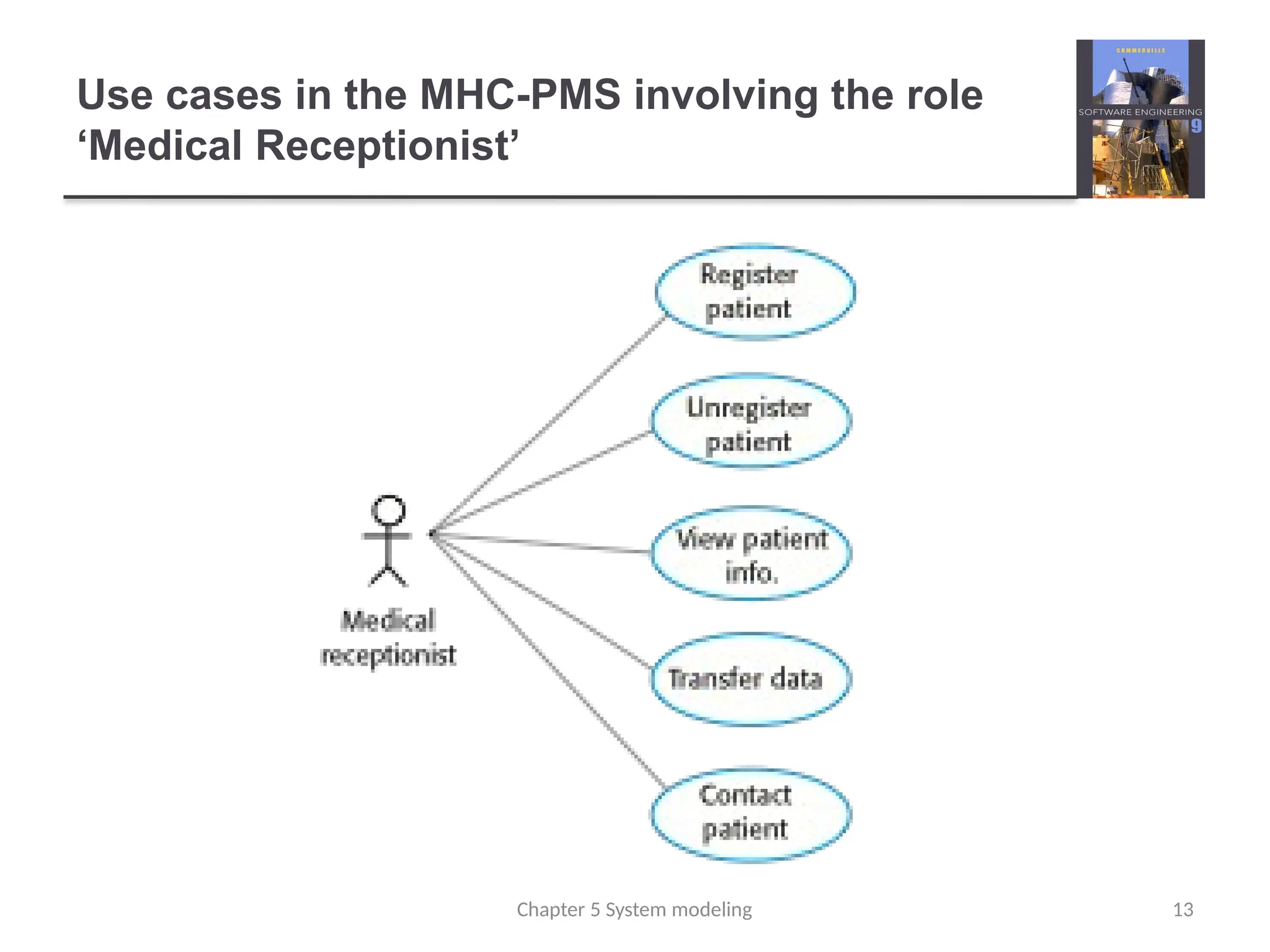
13.
Use cases inthe MHC-PMS involving the role
‘Medical Receptionist’
13
Chapter 5 System modeling
14.
Sequence diagrams
Sequencediagrams are part of the UML and are used to
model the interactions between the actors and the
objects within a system.
A sequence diagram shows the sequence of interactions
that take place during a particular use case or use case
instance.
The objects and actors involved are listed along the top
of the diagram, with a dotted line drawn vertically from
these.
Interactions between objects are indicated by annotated
arrows.
14
Chapter 5 System modeling
Structural models
Structuralmodels of software display the organization of
a system in terms of the components that make up that
system and their relationships.
Structural models may be static models, which show the
structure of the system design, or dynamic models,
which show the organization of the system when it is
executing.
You create structural models of a system when you are
discussing and designing the system architecture.
17
Chapter 5 System modeling
18.
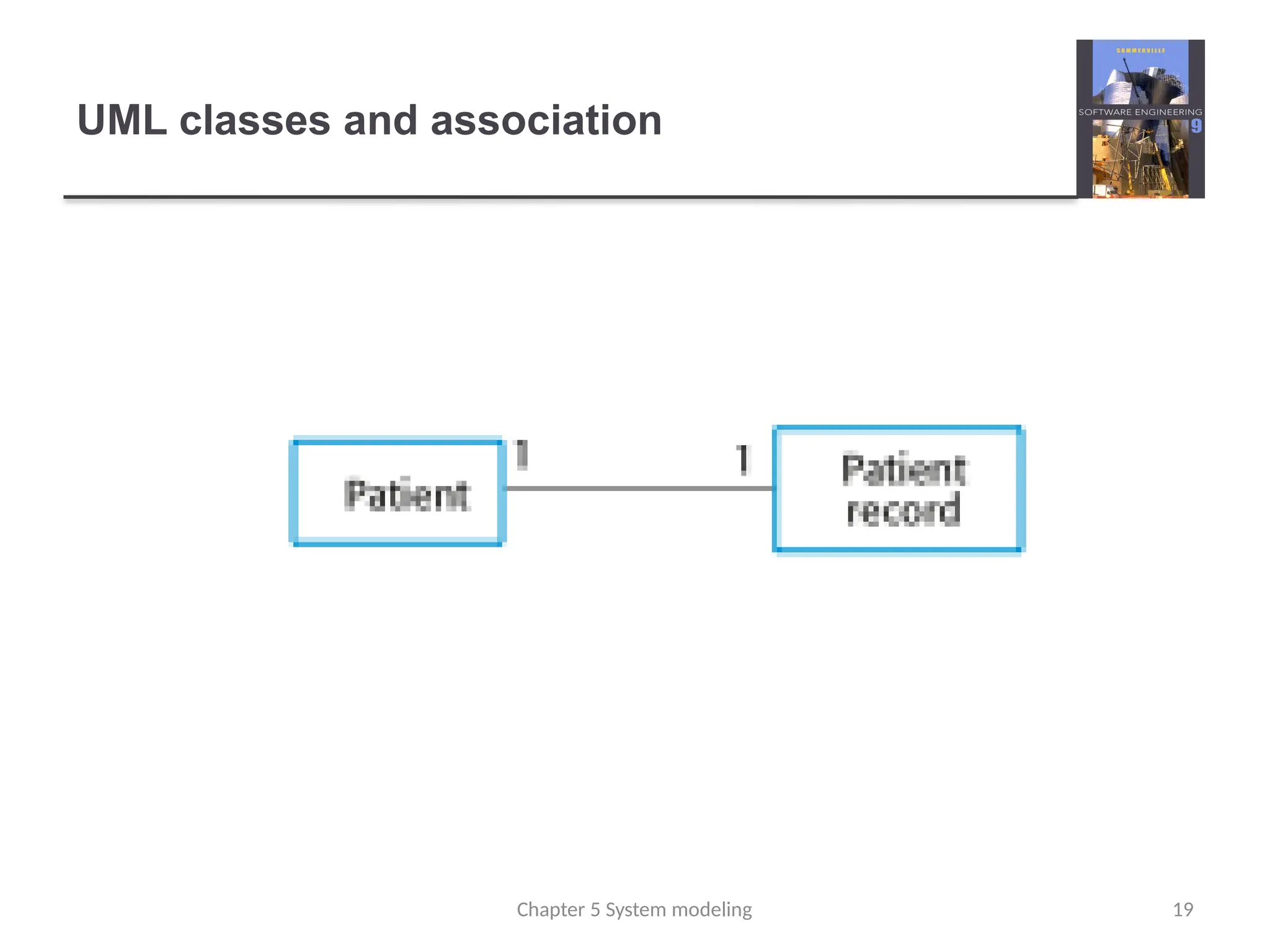
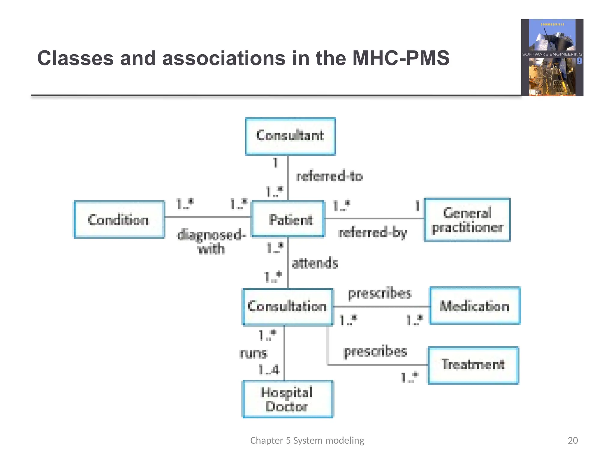
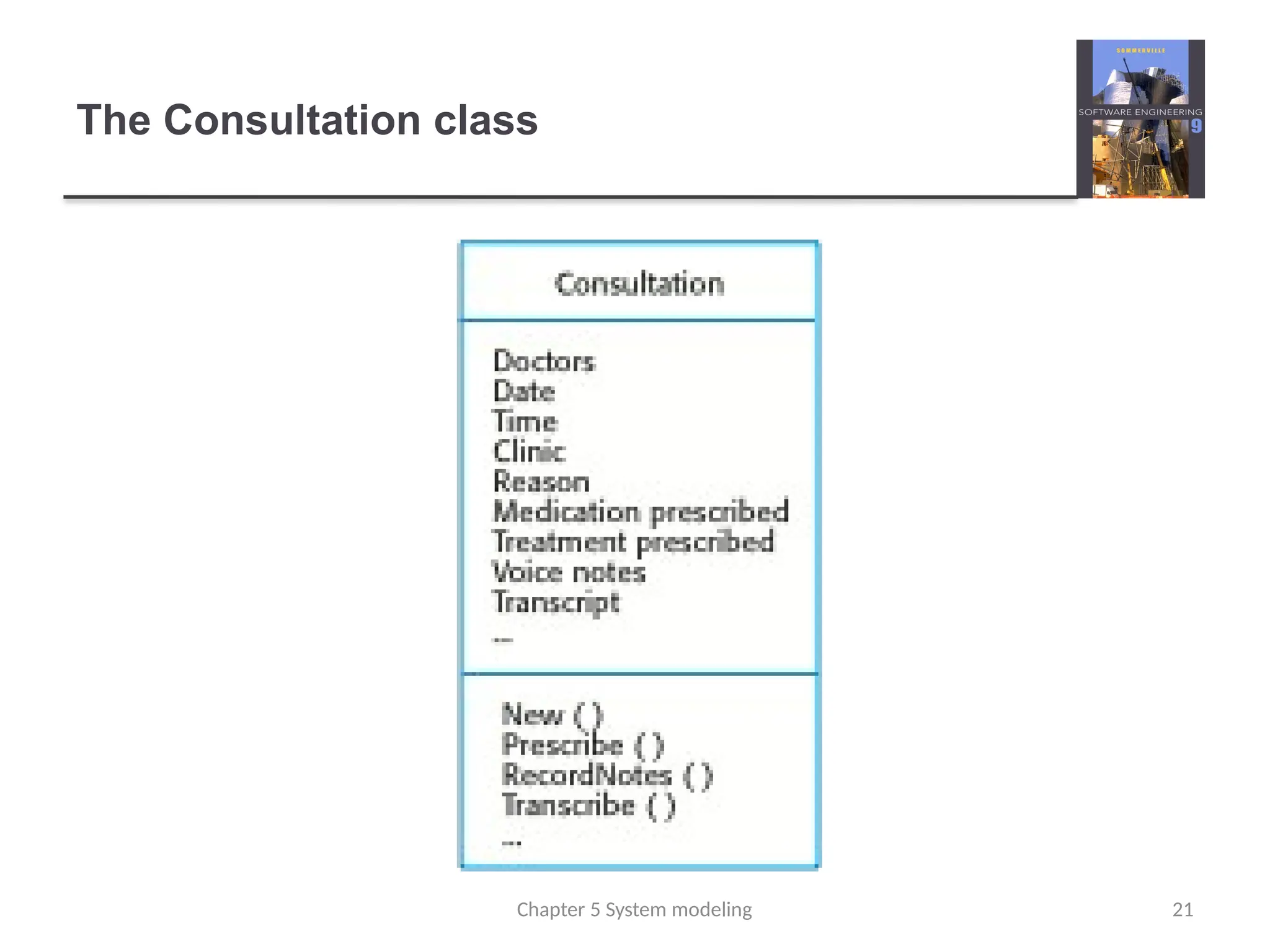
Class diagrams
Classdiagrams are used when developing an object-
oriented system model to show the classes in a system
and the associations between these classes.
An object class can be thought of as a general definition
of one kind of system object.
An association is a link between classes that indicates
that there is some relationship between these classes.
When you are developing models during the early stages
of the software engineering process, objects represent
something in the real world, such as a patient, a
prescription, doctor, etc.
18
Chapter 5 System modeling
Key points
Amodel is an abstract view of a system that ignores system details.
Complementary system models can be developed to show the
system’s context, interactions, structure and behavior.
Context models show how a system that is being modeled is
positioned in an environment with other systems and processes.
Use case diagrams and sequence diagrams are used to describe
the interactions between users and systems in the system being
designed. Use cases describe interactions between a system and
external actors; sequence diagrams add more information to these
by showing interactions between system objects.
Structural models show the organization and architecture of a
system. Class diagrams are used to define the static structure of
classes in a system and their associations.
Chapter 5 System modeling 22
Generalization
Generalization isan everyday technique that we use to
manage complexity.
Rather than learn the detailed characteristics of every
entity that we experience, we place these entities in
more general classes (animals, cars, houses, etc.) and
learn the characteristics of these classes.
This allows us to infer that different members of these
classes have some common characteristics e.g.
squirrels and rats are rodents.
Chapter 5 System modeling 24
25.
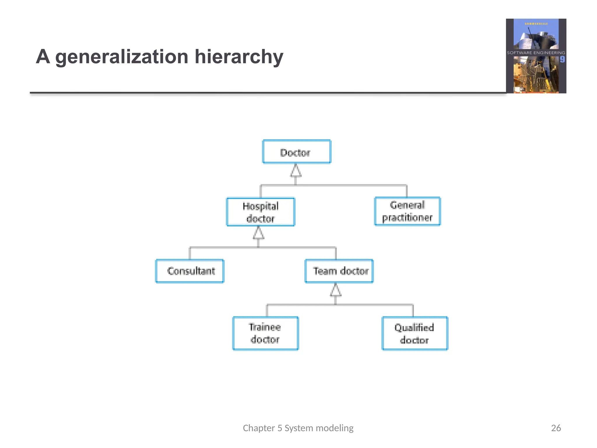
Generalization
In modelingsystems, it is often useful to examine the classes in
a system to see if there is scope for generalization. If changes
are proposed, then you do not have to look at all classes in the
system to see if they are affected by the change.
In object-oriented languages, such as Java, generalization is
implemented using the class inheritance mechanisms built into
the language.
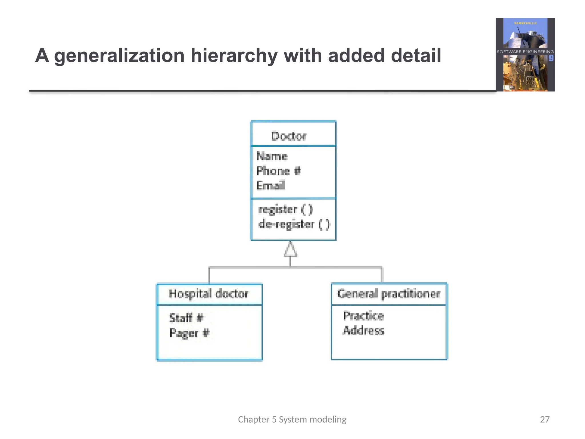
In a generalization, the attributes and operations associated with
higher-level classes are also associated with the lower-level
classes.
The lower-level classes are subclasses inherit the attributes and
operations from their superclasses. These lower-level classes
then add more specific attributes and operations.
Chapter 5 System modeling 25
Behavioral models
Behavioralmodels are models of the dynamic behavior
of a system as it is executing. They show what happens
or what is supposed to happen when a system responds
to a stimulus from its environment.
You can think of these stimuli as being of two types:
Data Some data arrives that has to be processed by the system.
Events Some event happens that triggers system processing.
Events may have associated data, although this is not always
the case.
30
Chapter 5 System modeling
31.
Data-driven modeling
Manybusiness systems are data-processing systems
that are primarily driven by data. They are controlled by
the data input to the system, with relatively little external
event processing.
Data-driven models show the sequence of actions
involved in processing input data and generating an
associated output.
They are particularly useful during the analysis of
requirements as they can be used to show end-to-end
processing in a system.
31
Chapter 5 System modeling
32.
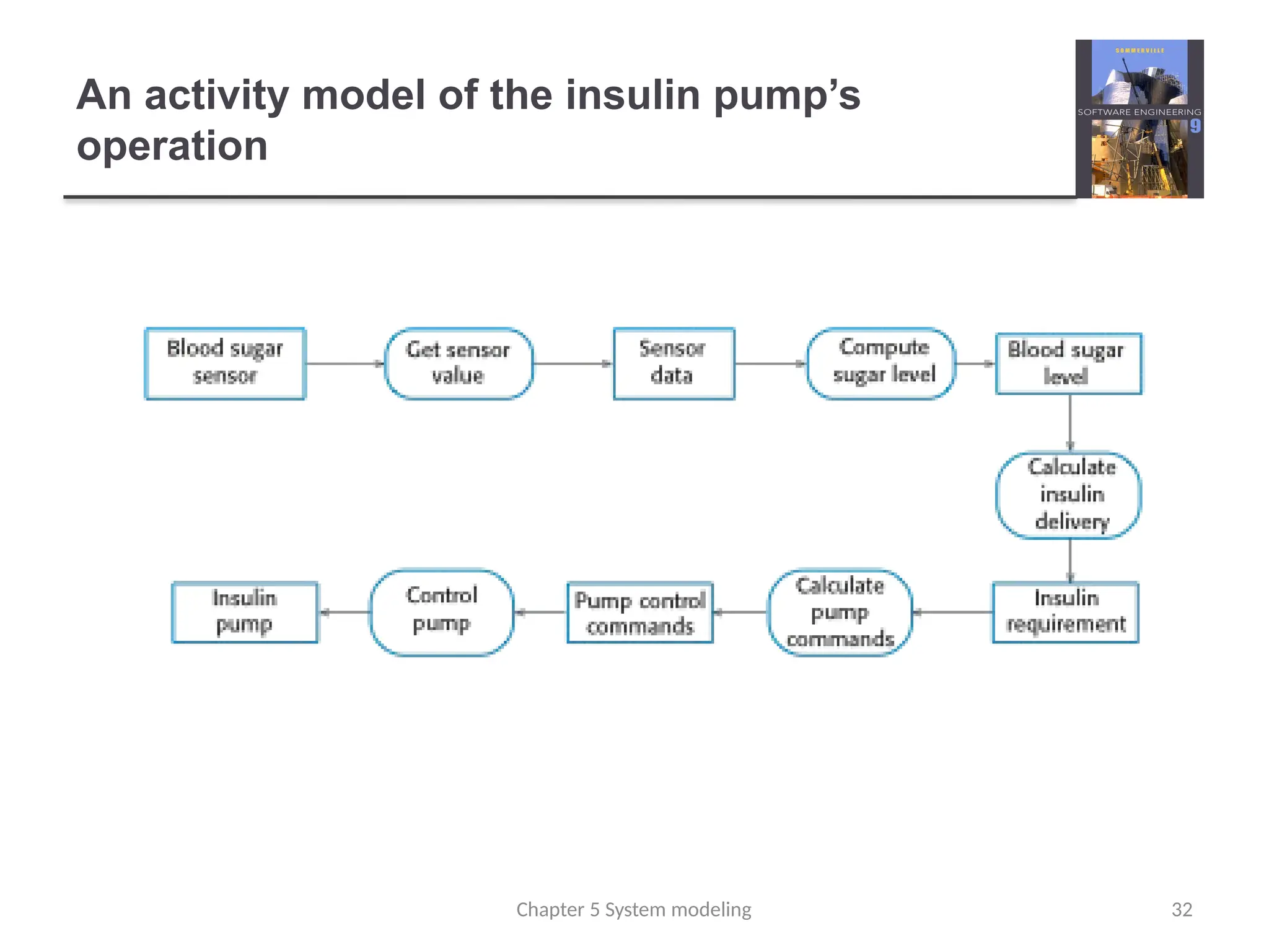
An activity modelof the insulin pump’s
operation
32
Chapter 5 System modeling
33.
Event-driven modeling
Real-timesystems are often event-driven, with minimal
data processing. For example, a landline phone
switching system responds to events such as ‘receiver
off hook’ by generating a dial tone.
Event-driven modeling shows how a system responds to
external and internal events.
It is based on the assumption that a system has a finite
number of states and that events (stimuli) may cause a
transition from one state to another.
Chapter 5 System modeling 33
34.
State machine models
These model the behaviour of the system in response to
external and internal events.
They show the system’s responses to stimuli so are
often used for modelling real-time systems.
State machine models show system states as nodes and
events as arcs between these nodes. When an event
occurs, the system moves from one state to another.
Statecharts are an integral part of the UML and are used
to represent state machine models.
34
Chapter 5 System modeling
Model-driven engineering
Model-drivenengineering (MDE) is an approach to
software development where models rather than
programs are the principal outputs of the development
process.
The programs that execute on a hardware/software
platform are then generated automatically from the
models.
Proponents of MDE argue that this raises the level of
abstraction in software engineering so that engineers no
longer have to be concerned with programming language
details or the specifics of execution platforms.
Chapter 5 System modeling 36
37.
Usage of model-drivenengineering
Model-driven engineering is still at an early stage of
development, and it is unclear whether or not it will have
a significant effect on software engineering practice.
Pros
Allows systems to be considered at higher levels of abstraction
Generating code automatically means that it is cheaper to adapt
systems to new platforms.
Cons
Models for abstraction and not necessarily right for
implementation.
Savings from generating code may be outweighed by the costs
of developing translators for new platforms.
Chapter 5 System modeling 37
38.
Model driven architecture
Model-driven architecture (MDA) was the precursor of
more general model-driven engineering
MDA is a model-focused approach to software design
and implementation that uses a subset of UML models to
describe a system.
Models at different levels of abstraction are created.
From a high-level, platform independent model, it is
possible, in principle, to generate a working program
without manual intervention.
Chapter 5 System modeling 38
39.
Key points
Behavioralmodels are used to describe the dynamic behavior
of an executing system. This behavior can be modeled from
the perspective of the data processed by the system, or by
the events that stimulate responses from a system.
Activity diagrams may be used to model the processing of
data, where each activity represents one process step.
State diagrams are used to model a system’s behavior in
response to internal or external events.
Model-driven engineering is an approach to software
development in which a system is represented as a set of
models that can be automatically transformed to executable
code.
Chapter 5 System modeling 39