COMPUTER
• A computeris an electronic machine capable of solving and processing problems by
executing pre-defined instructions. It enables:
• Acquiring information
• Storing information
• Processing information
• Outputting information
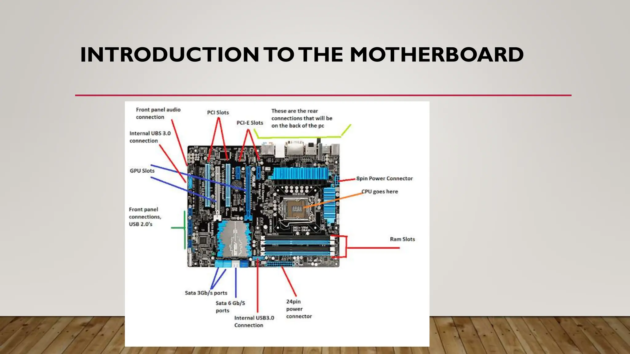
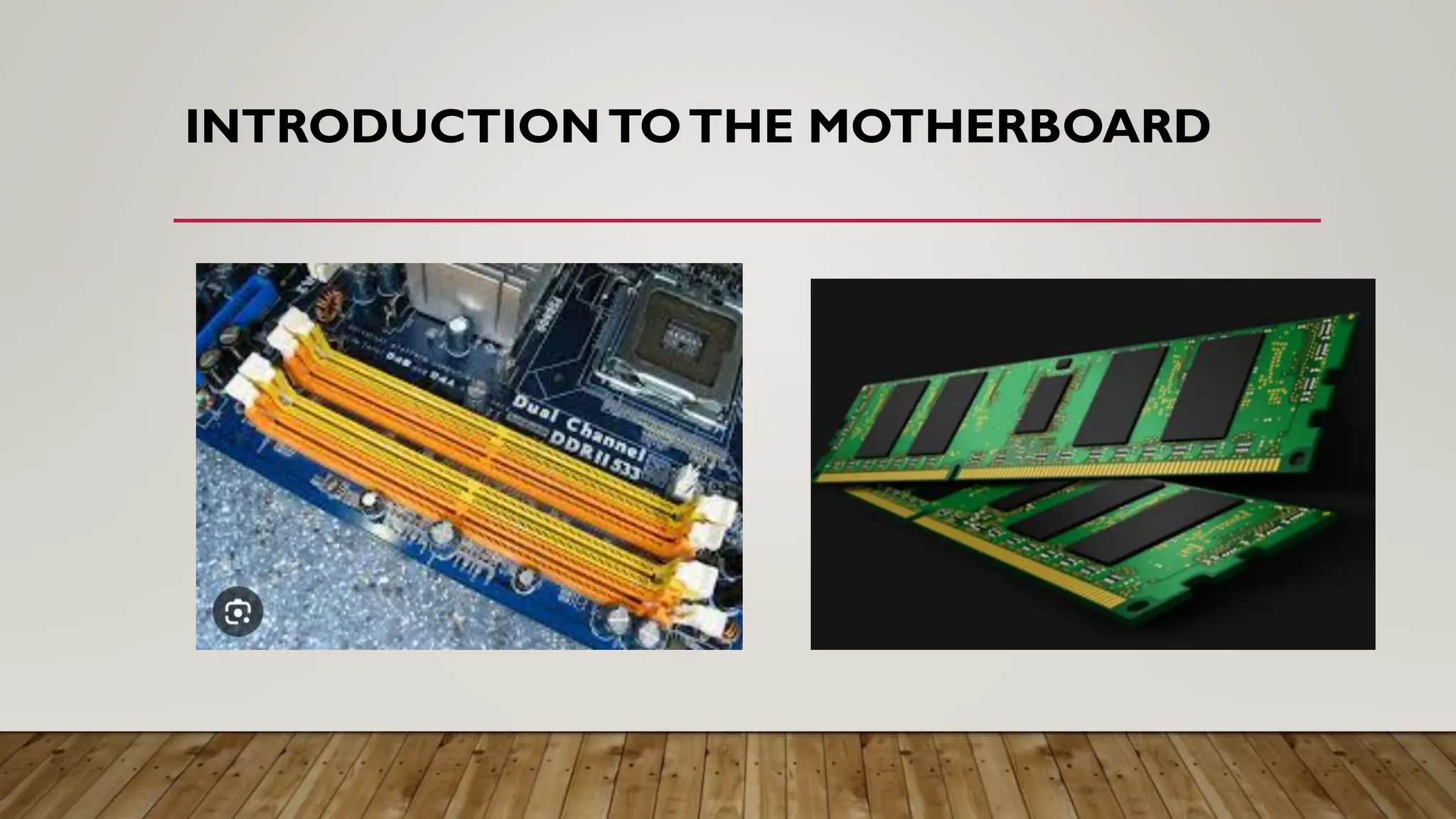
CHARACTERISTICS OF AMOTHERBOARD
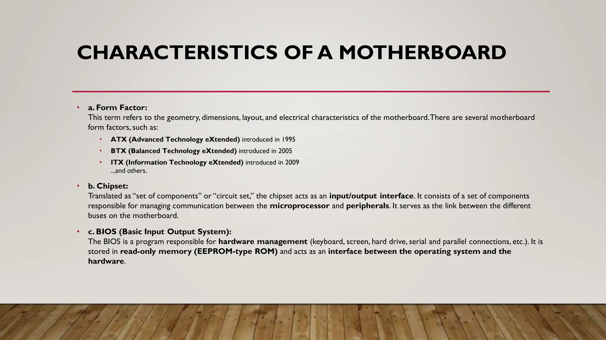
• a. Form Factor:
This term refers to the geometry, dimensions, layout, and electrical characteristics of the motherboard.There are several motherboard
form factors, such as:
• ATX (Advanced Technology eXtended) introduced in 1995
• BTX (Balanced Technology eXtended) introduced in 2005
• ITX (Information Technology eXtended) introduced in 2009
...and others.
• b. Chipset:
Translated as “set of components” or “circuit set,” the chipset acts as an input/output interface. It consists of a set of components
responsible for managing communication between the microprocessor and peripherals. It serves as the link between the different
buses on the motherboard.
• c. BIOS (Basic Input Output System):
The BIOS is a program responsible for hardware management (keyboard, screen, hard drive, serial and parallel connections, etc.). It is
stored in read-only memory (EEPROM-type ROM) and acts as an interface between the operating system and the
hardware.
7.
CHARACTERISTICS OF AMOTHERBOARD
• d. Socket Types: There are two main categories of processor mounts:
• Sockets: A socket is the connector designed for the processor. It is a square-shaped connector with a large number of small pins into which the processor is directly inserted.
• Slots: A slot is a rectangular slot into which a component is inserted. Depending on the type of component accommodated, other terms may be used to refer to slots:
• e. Connection Ports: These allow peripherals to be connected to the various buses on the motherboard. There are two types of connectors (or ports):
• Internal Connectors: These include connectors for:
• Expansion cards (PCI – Peripheral Component Interconnect, ISA – Industry Standard Architecture, AGP – Accelerated Graphics Port)
• Mass storage devices (IDE also called PATA – Parallel ATA, SCSI – Small Computer System Interface, SATA – Serial ATA)
• External Connectors (also called I/O Panel – Input/Output Panel): These include ports for connecting external peripherals to the computer:
• USB (Universal Serial Bus)
• RJ45 (Registered Jack)
• VGA (Video Graphics Array)
• DVI (Digital Visual Interface)
• HDMI (High Definition Multimedia Interface)
• DisplayPort
• Analog audio
• Digital audio
• FireWire
8.
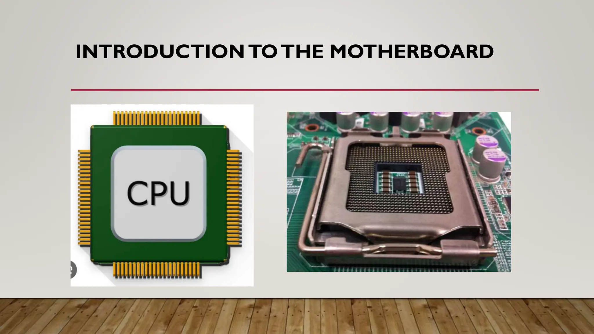
PROCESSOR
• The processor(CPU, for Central Processing Unit) is the brain of the computer. It
enables data exchange between the various components (hard drive, RAM, graphics card,
etc.), manipulates digital information – meaning information encoded in binary form – and
executes instructions stored in memory. Its performance is measured in Hertz.
PROCESSOR
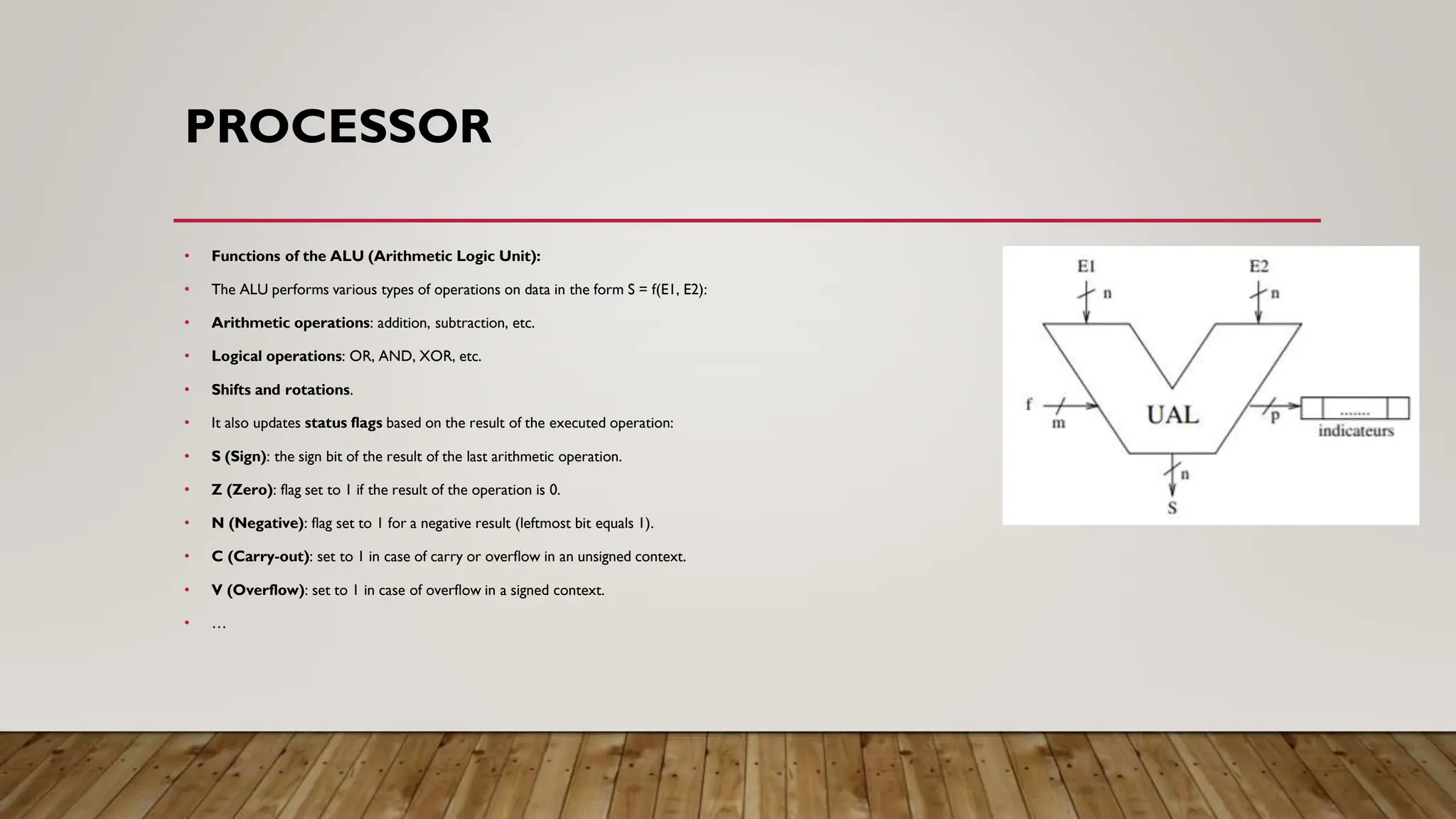
• Functions ofthe ALU (Arithmetic Logic Unit):
• The ALU performs various types of operations on data in the form S = f(E1, E2):
• Arithmetic operations: addition, subtraction, etc.
• Logical operations: OR, AND, XOR, etc.
• Shifts and rotations.
• It also updates status flags based on the result of the executed operation:
• S (Sign): the sign bit of the result of the last arithmetic operation.
• Z (Zero): flag set to 1 if the result of the operation is 0.
• N (Negative): flag set to 1 for a negative result (leftmost bit equals 1).
• C (Carry-out): set to 1 in case of carry or overflow in an unsigned context.
• V (Overflow): set to 1 in case of overflow in a signed context.
• …
11.
BUS
• A busis a set of wires (electrical conductors) that enables the transmission of binary information between computer components. There are several specialized
buses depending on the types of peripherals involved and the nature of the information being transmitted: addresses, commands, or data.
• 2.4.1. Characteristics of a Bus
• A bus is characterized by:
• a. Width:
A bus is characterized by the volume of information that can be sent in parallel (expressed in bits), corresponding to the number of physical lines on which data is
sent simultaneously. Thus, the width refers to the number of bits a bus can transmit at the same time.
• 1 wire transmits 1 bit
• 1 bus with n wires = n-bit bus
Example: A 32-wire ribbon cable can transmit 32 bits in parallel.
• b. Speed:
This is the number of data packets sent or received per second. It is also defined by its frequency (expressed in Hertz).
A cycle refers to each sending or receiving of data. A memory cycle ensures the transfer of one memory word:
Memory cycle (s) = 1 / frequency
12.
BUS
• c.Throughput:
The maximumthroughput of a bus (or maximum transfer rate) is the amount of data it can transfer per unit of time, calculated by
multiplying its width by its frequency.
• Throughput (bytes/s) = (number of transfers per second * width) / 8
Bandwidth (in MB/s) = bus width (in bytes) * frequency (in Hz)
• Exercise:
A 8-bit bus, clocked at a frequency of 100 MHz. Calculate the transfer rate.
• Solution:
The bus has a transfer rate equal to:
Transfer rate = bus width * frequency
= 8 * 100 × 10⁶
= 8 × 10⁸ bits/s
= 10⁸ bytes/s
= 10⁵ KB/s
= 100 MB/s
13.
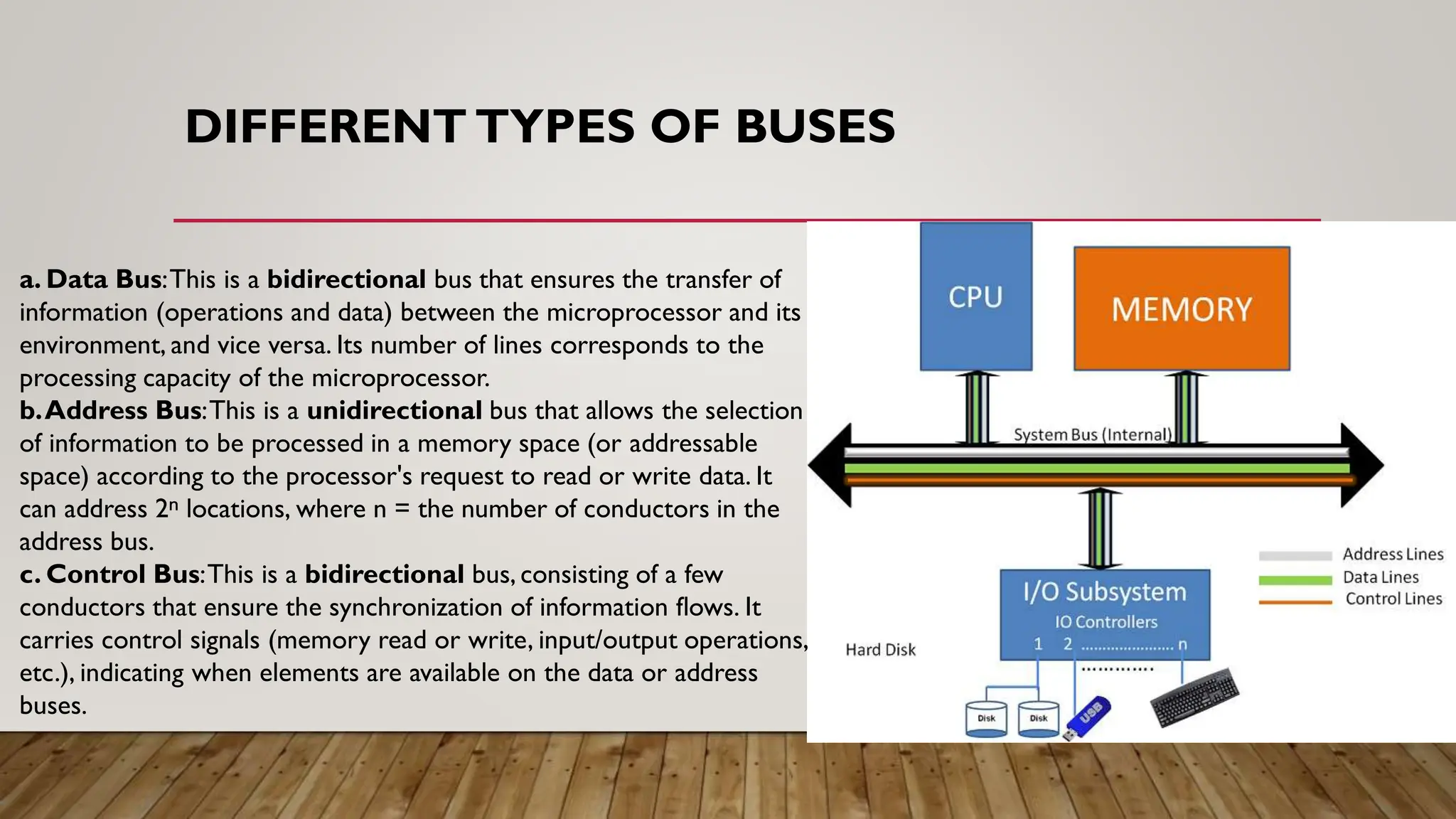
DIFFERENT TYPES OFBUSES
a. Data Bus:This is a bidirectional bus that ensures the transfer of
information (operations and data) between the microprocessor and its
environment, and vice versa. Its number of lines corresponds to the
processing capacity of the microprocessor.
b.Address Bus:This is a unidirectional bus that allows the selection
of information to be processed in a memory space (or addressable
space) according to the processor's request to read or write data. It
can address 2ⁿ locations, where n = the number of conductors in the
address bus.
c. Control Bus:This is a bidirectional bus, consisting of a few
conductors that ensure the synchronization of information flows. It
carries control signals (memory read or write, input/output operations,
etc.), indicating when elements are available on the data or address
buses.
14.
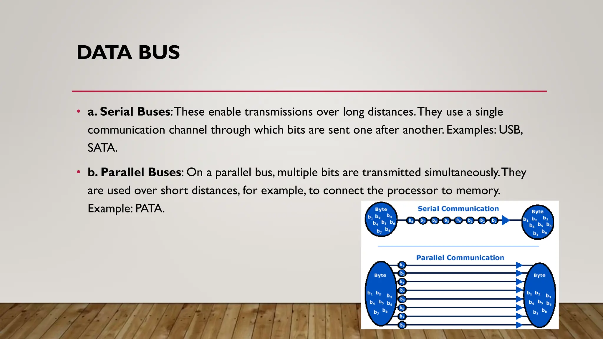
DATA BUS
• a.Serial Buses:These enable transmissions over long distances.They use a single
communication channel through which bits are sent one after another. Examples: USB,
SATA.
• b. Parallel Buses: On a parallel bus, multiple bits are transmitted simultaneously.They
are used over short distances, for example, to connect the processor to memory.
Example: PATA.
15.
MAIN BUSES
• Acomputer typically has two main buses:
• a. System Bus (internal bus or front-side bus, abbreviated FSB):Allows the processor to
communicate with the system's main memory (RAM or random-access memory) through the
address and data buses.
• b. Expansion Bus (input/output bus):Allows various components connected to the
motherboard (USB, serial, parallel ports, cards plugged into PCI connectors, hard drives, CD-
ROM readers and burners, etc.) to communicate with each other. It also enables the addition
of new peripherals through the expansion connectors (called slots) connected to it.
• Note:
• The performance of a bus depends on its simultaneous transport capacity (16, 32, 64 bits,etc.) and
the electronics that control it (the chipset).
16.
REGISTERS
• When theprocessor executes instructions during processing, data is temporarily stored in small, fast
memory units (8, 16, 32, or 64 bits) called registers. Depending on the type of processor, the total
number of registers can range from about ten to several hundred.
• a. User-Visible Registers (can be manipulated by the programmer):A user register is a register that
can be referenced by instructions executed by the processor.There are different categories:
• Data Registers:Cannot be used for address calculation.
• Address Registers:Often dedicated to a specific addressing mode (containing base or index values).
• Condition Registers (flags): Consist of a series of independent bits,each set according to the result of an
operation.
• Other Registers:Have no specific function.
17.
REGISTERS
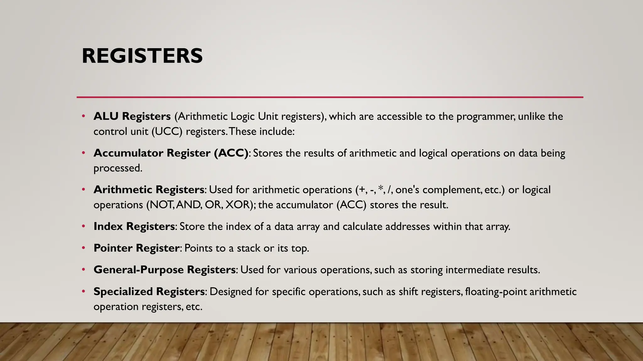
• ALU Registers(Arithmetic Logic Unit registers), which are accessible to the programmer, unlike the
control unit (UCC) registers.These include:
• Accumulator Register (ACC): Stores the results of arithmetic and logical operations on data being
processed.
• Arithmetic Registers: Used for arithmetic operations (+, -, *, /, one's complement,etc.) or logical
operations (NOT,AND, OR, XOR); the accumulator (ACC) stores the result.
• Index Registers: Store the index of a data array and calculate addresses within that array.
• Pointer Register: Points to a stack or its top.
• General-Purpose Registers: Used for various operations, such as storing intermediate results.
• Specialized Registers: Designed for specific operations,such as shift registers, floating-point arithmetic
operation registers, etc.
18.
REGISTERS
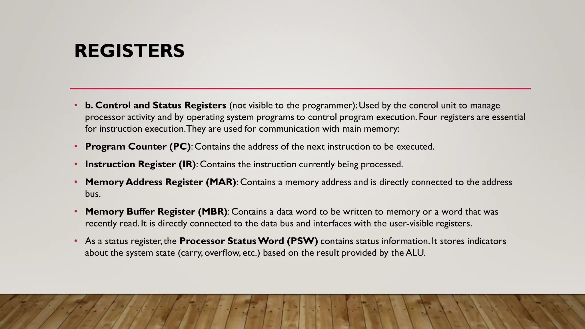
• b. Controland Status Registers (not visible to the programmer):Used by the control unit to manage
processor activity and by operating system programs to control program execution.Four registers are essential
for instruction execution.They are used for communication with main memory:
• Program Counter (PC): Contains the address of the next instruction to be executed.
• Instruction Register (IR): Contains the instruction currently being processed.
• Memory Address Register (MAR): Contains a memory address and is directly connected to the address
bus.
• Memory Buffer Register (MBR): Contains a data word to be written to memory or a word that was
recently read. It is directly connected to the data bus and interfaces with the user-visible registers.
• As a status register,the Processor Status Word (PSW) contains status information.It stores indicators
about the system state (carry, overflow, etc.) based on the result provided by the ALU.