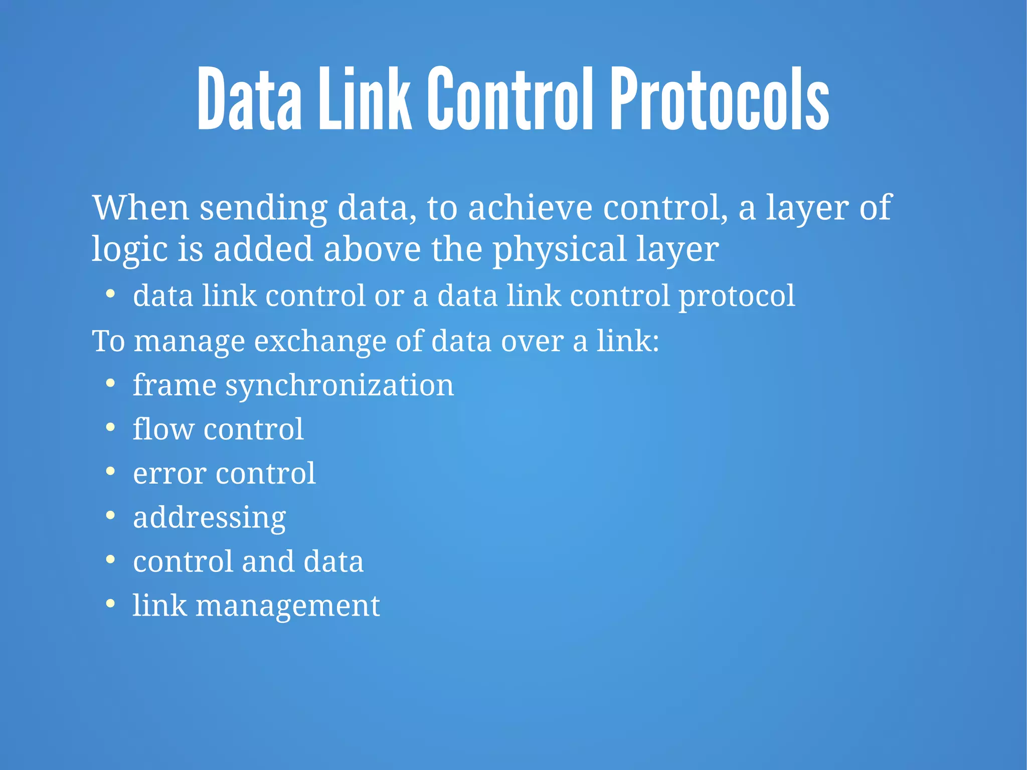
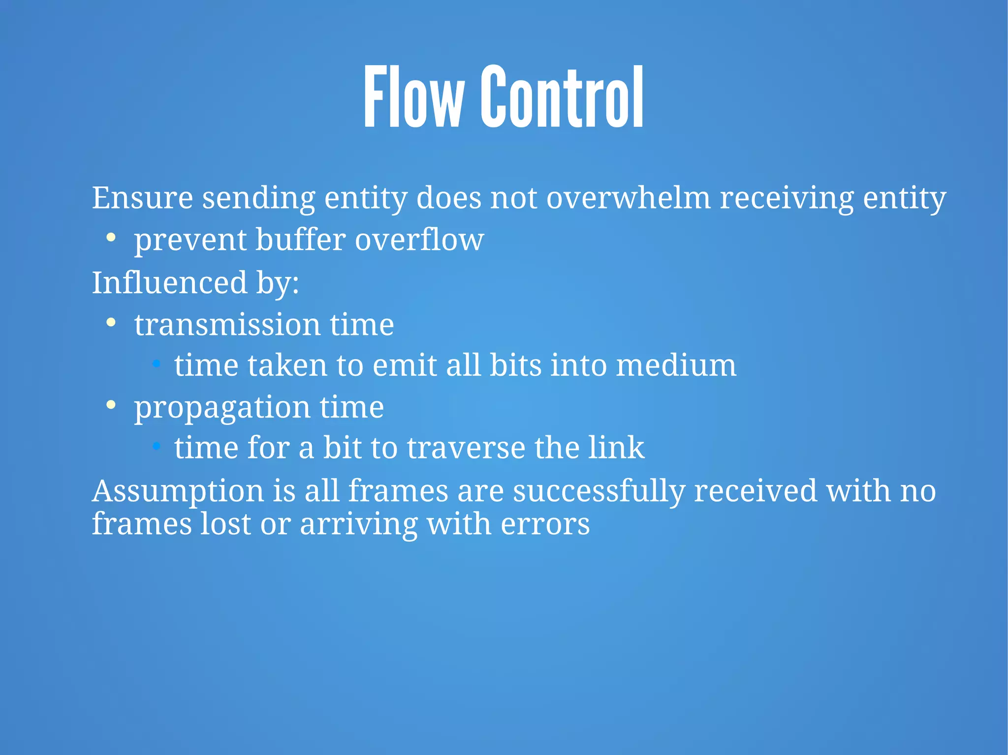
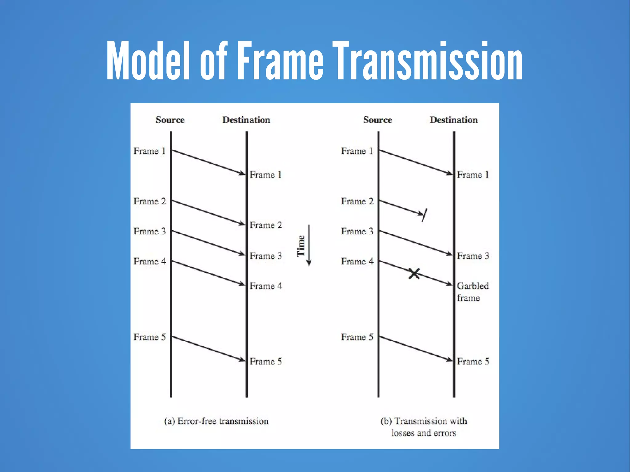
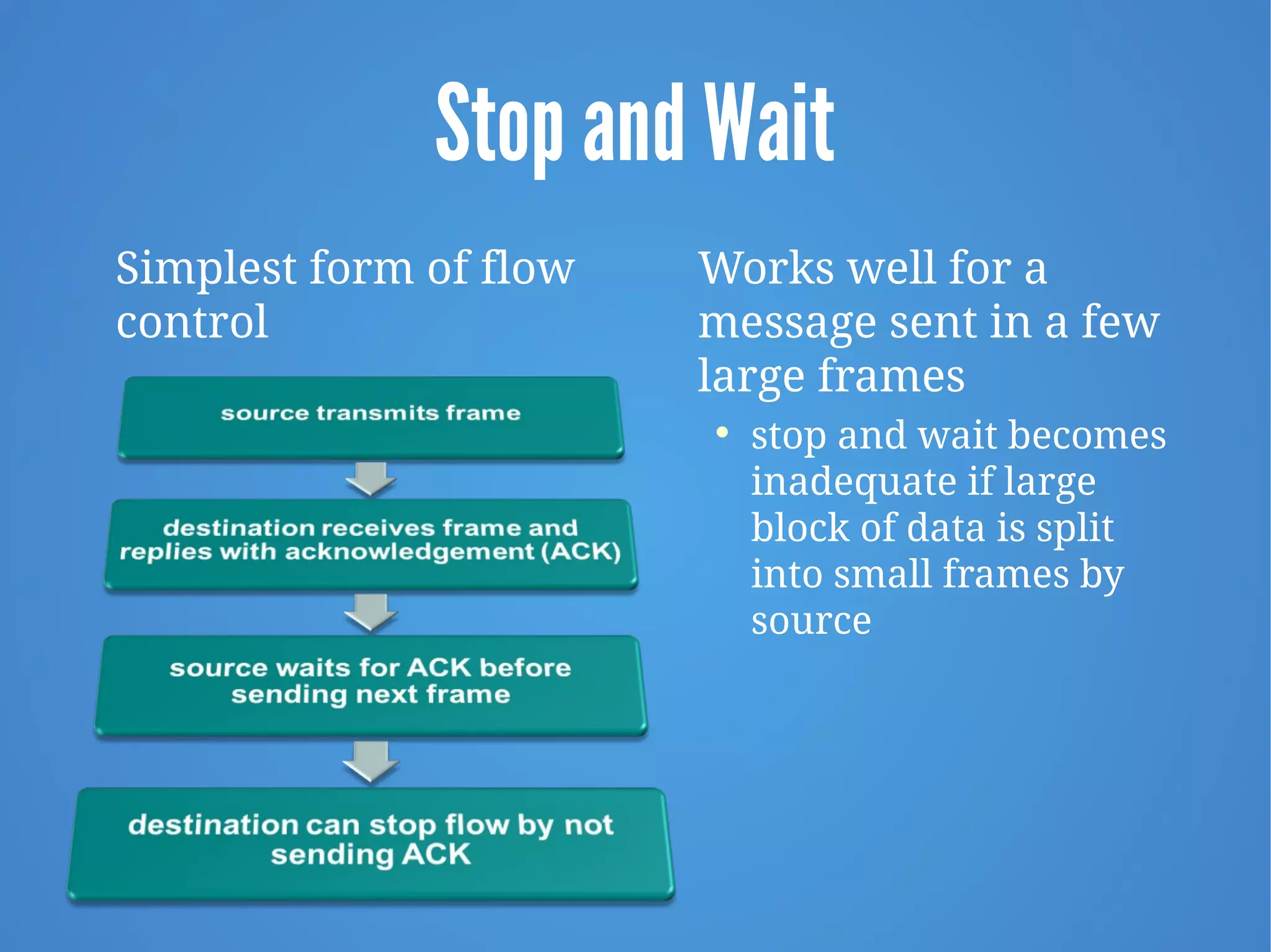
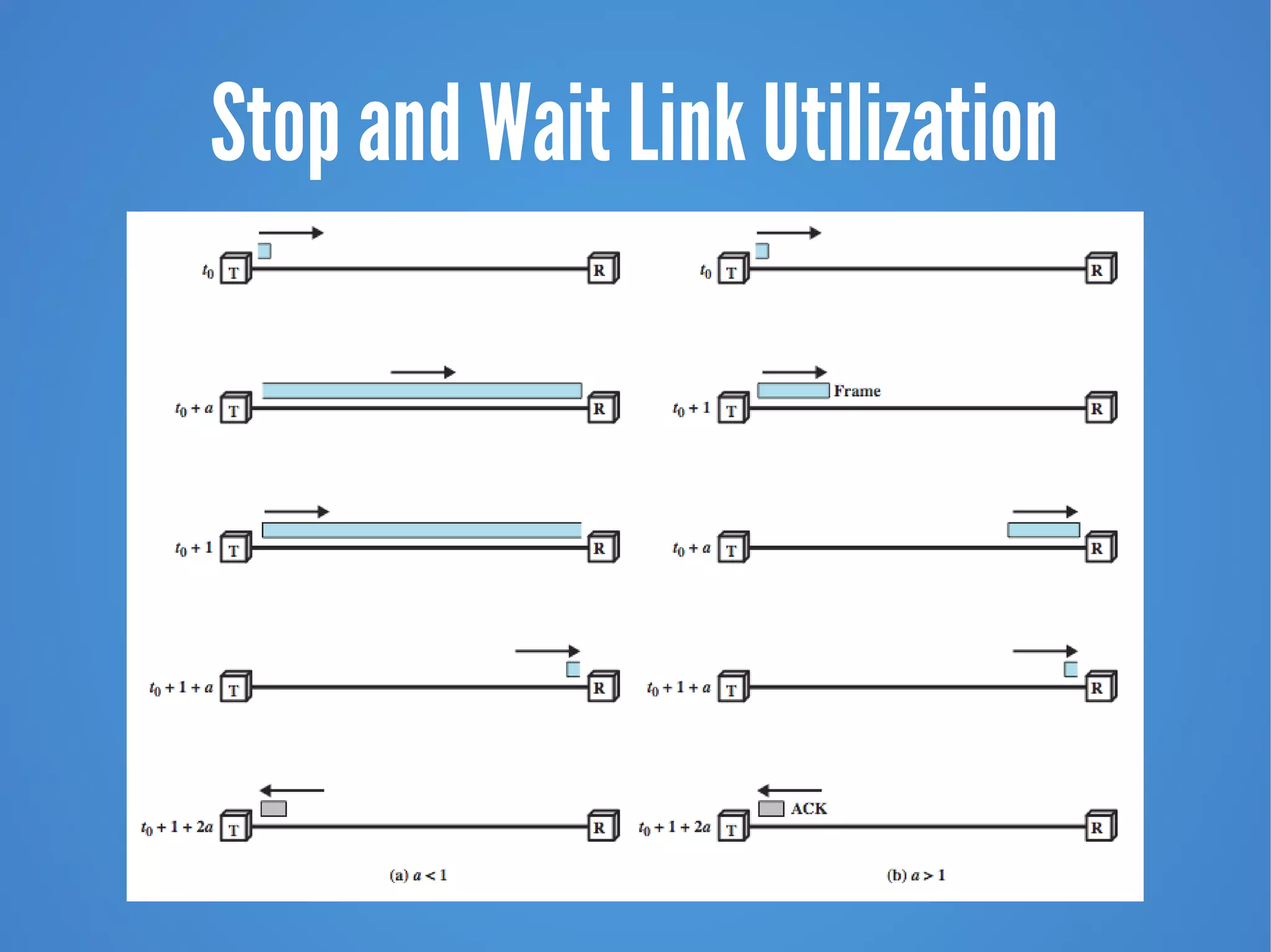
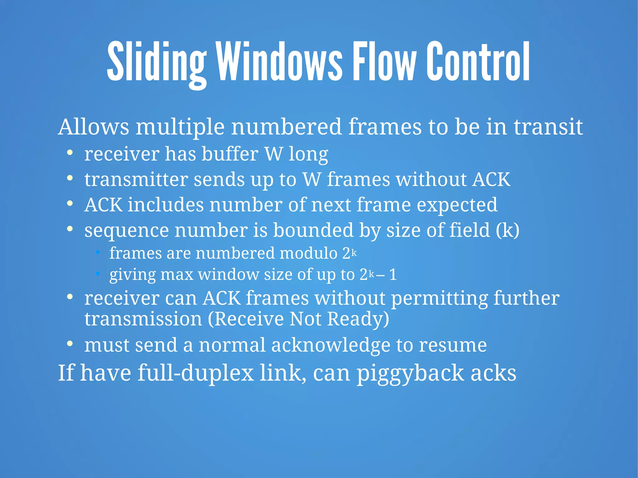
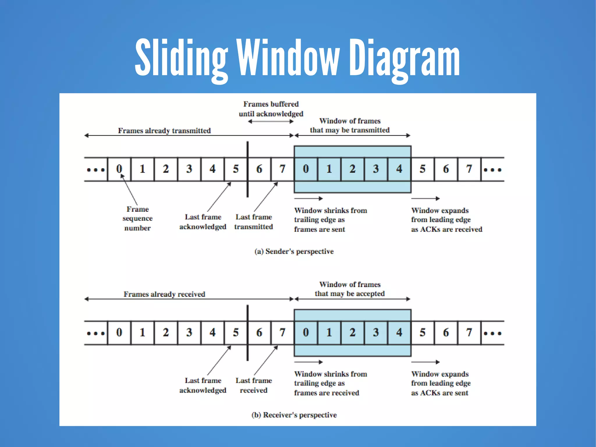
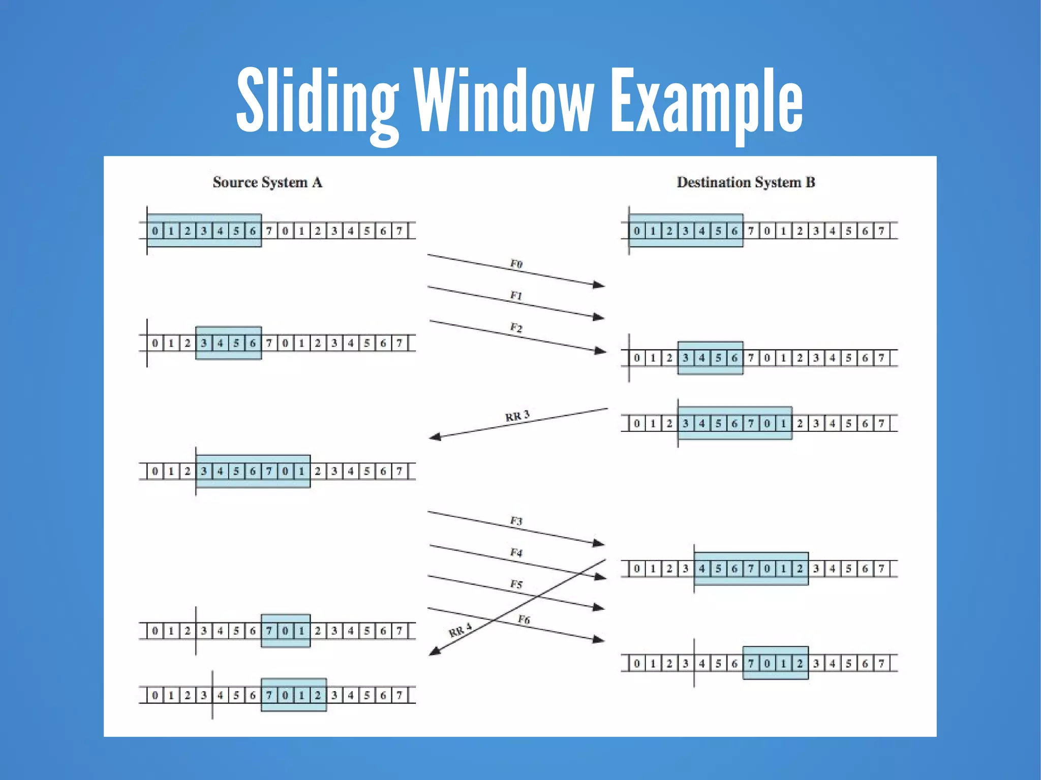
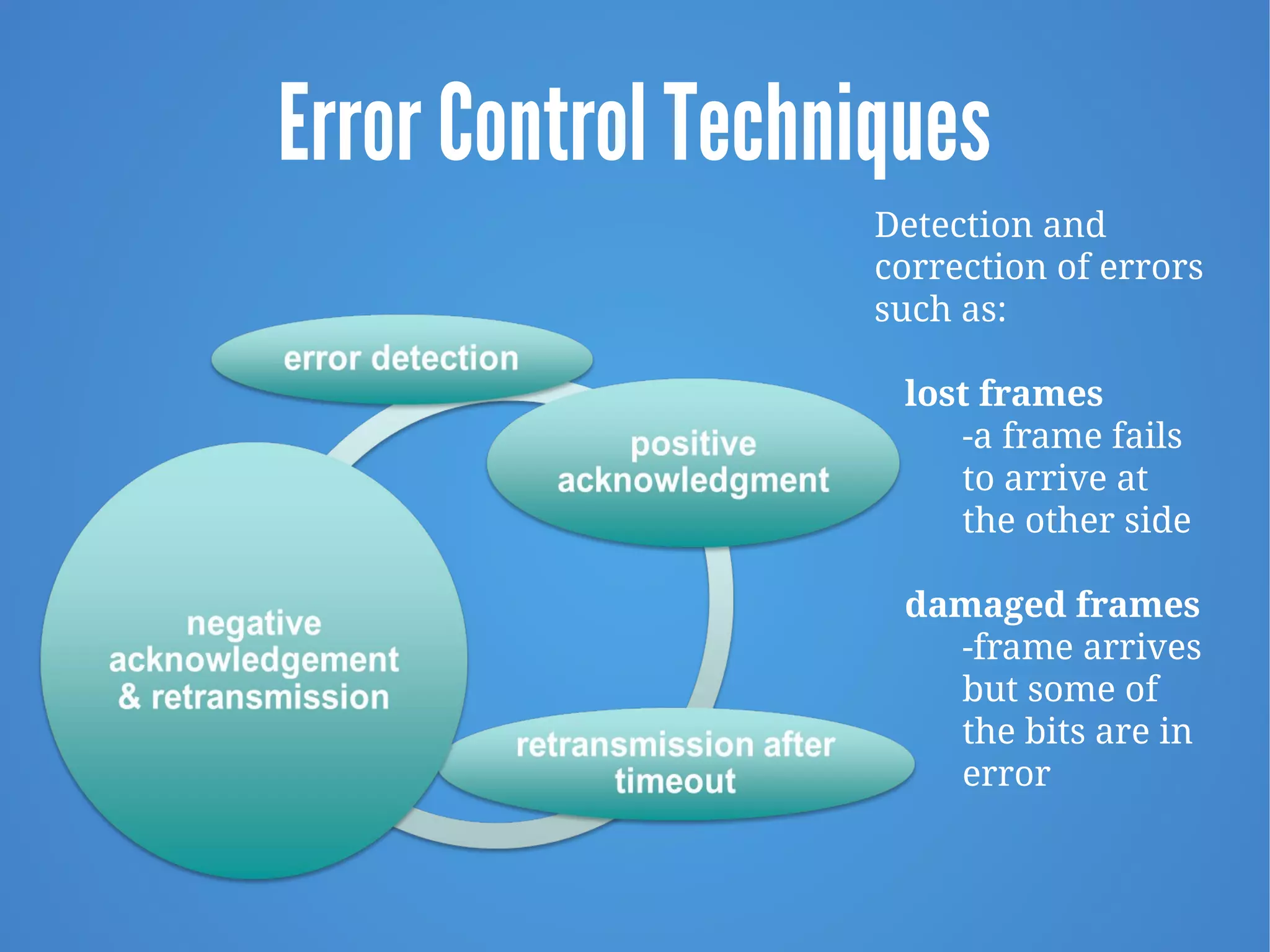
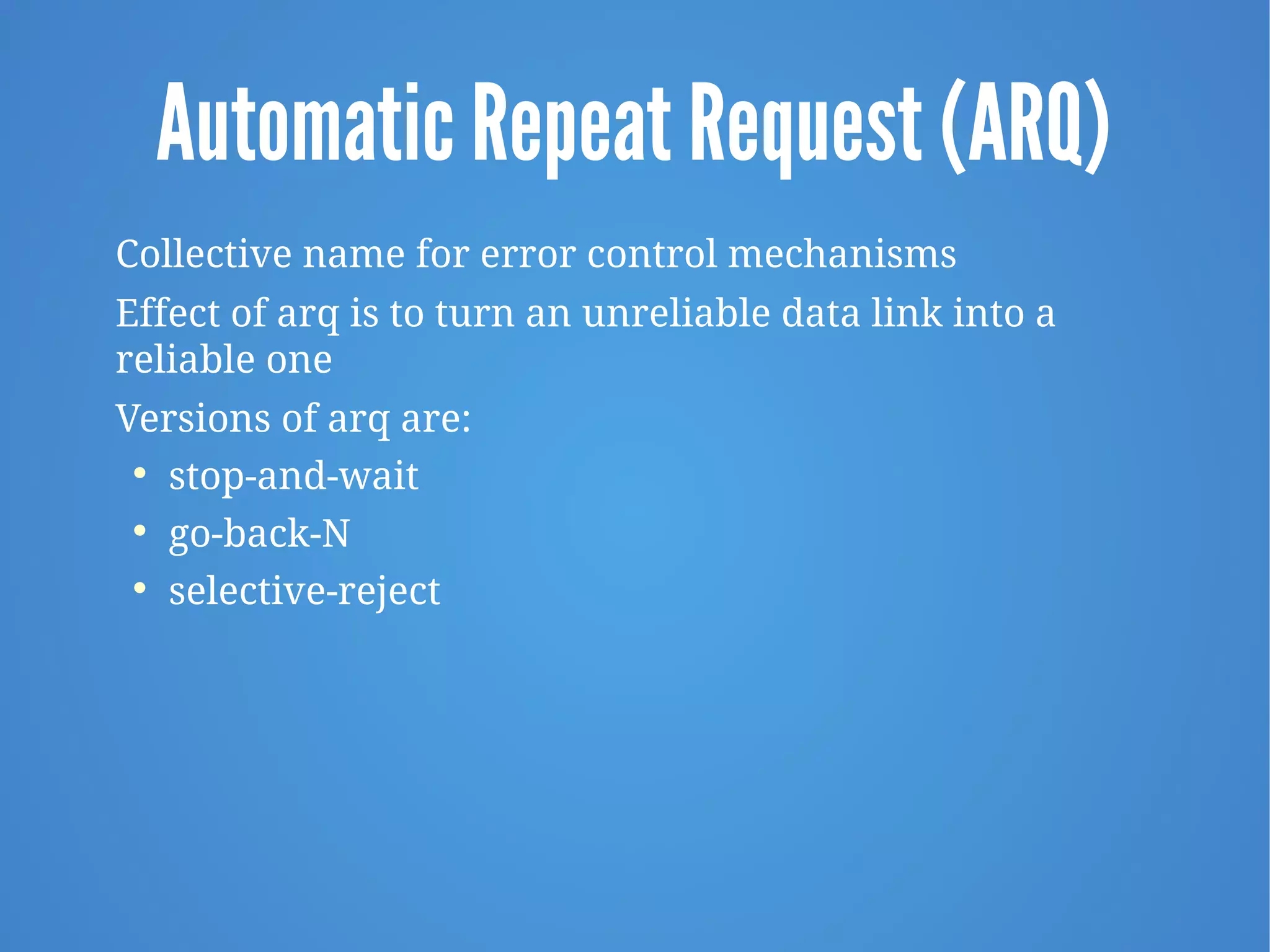
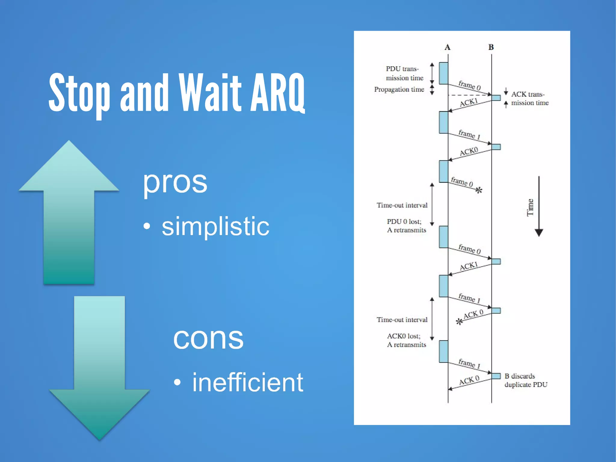
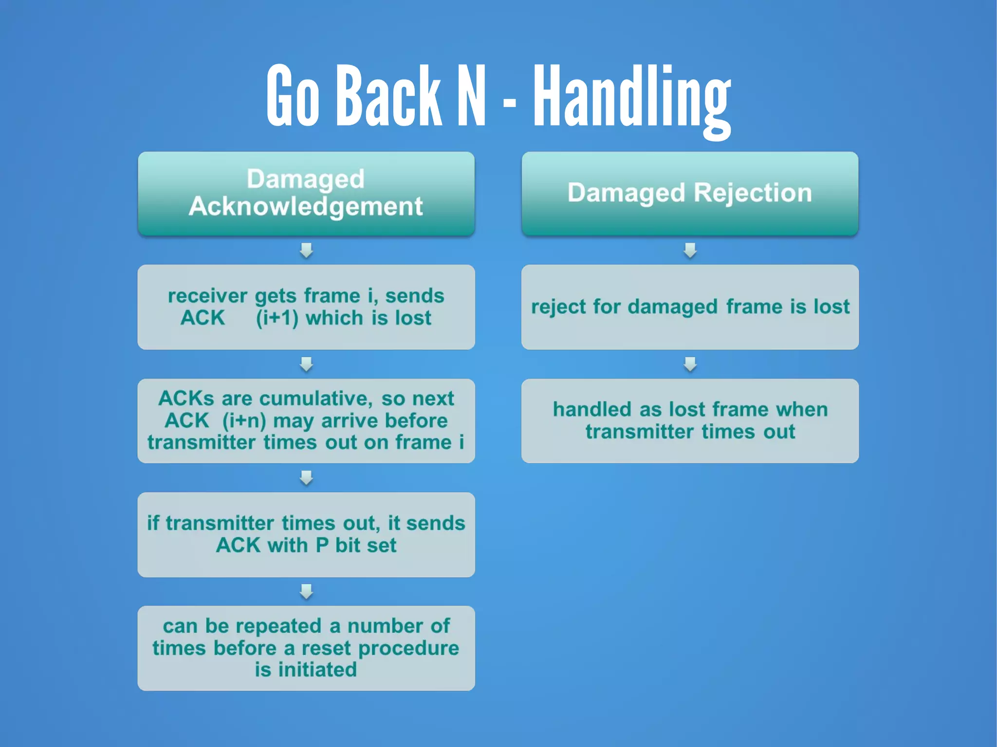
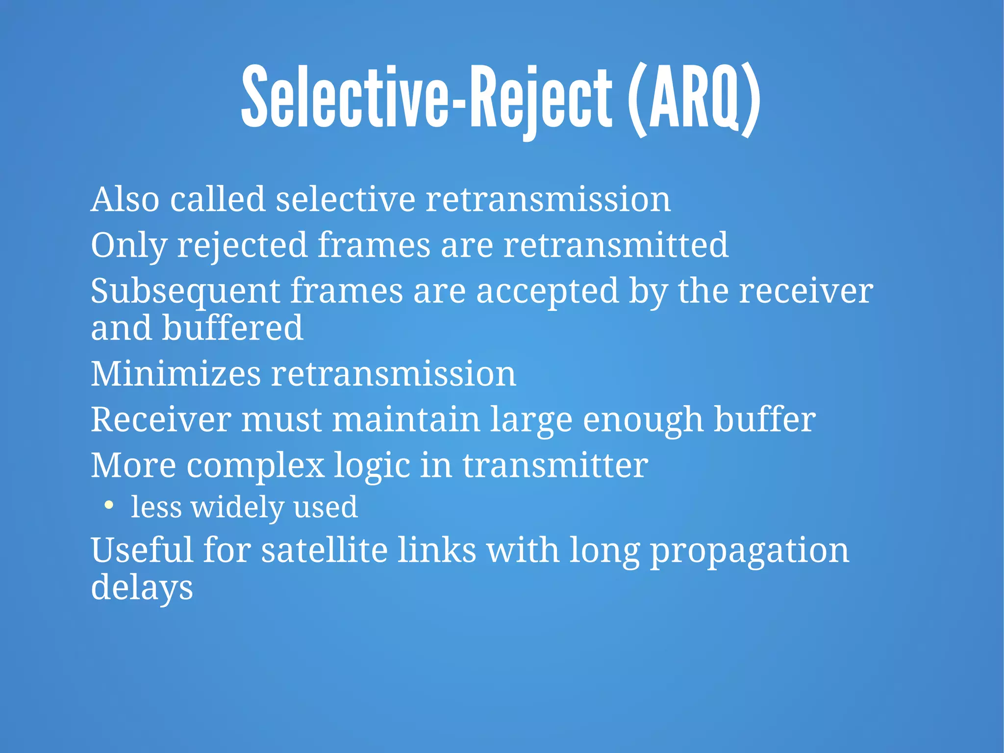
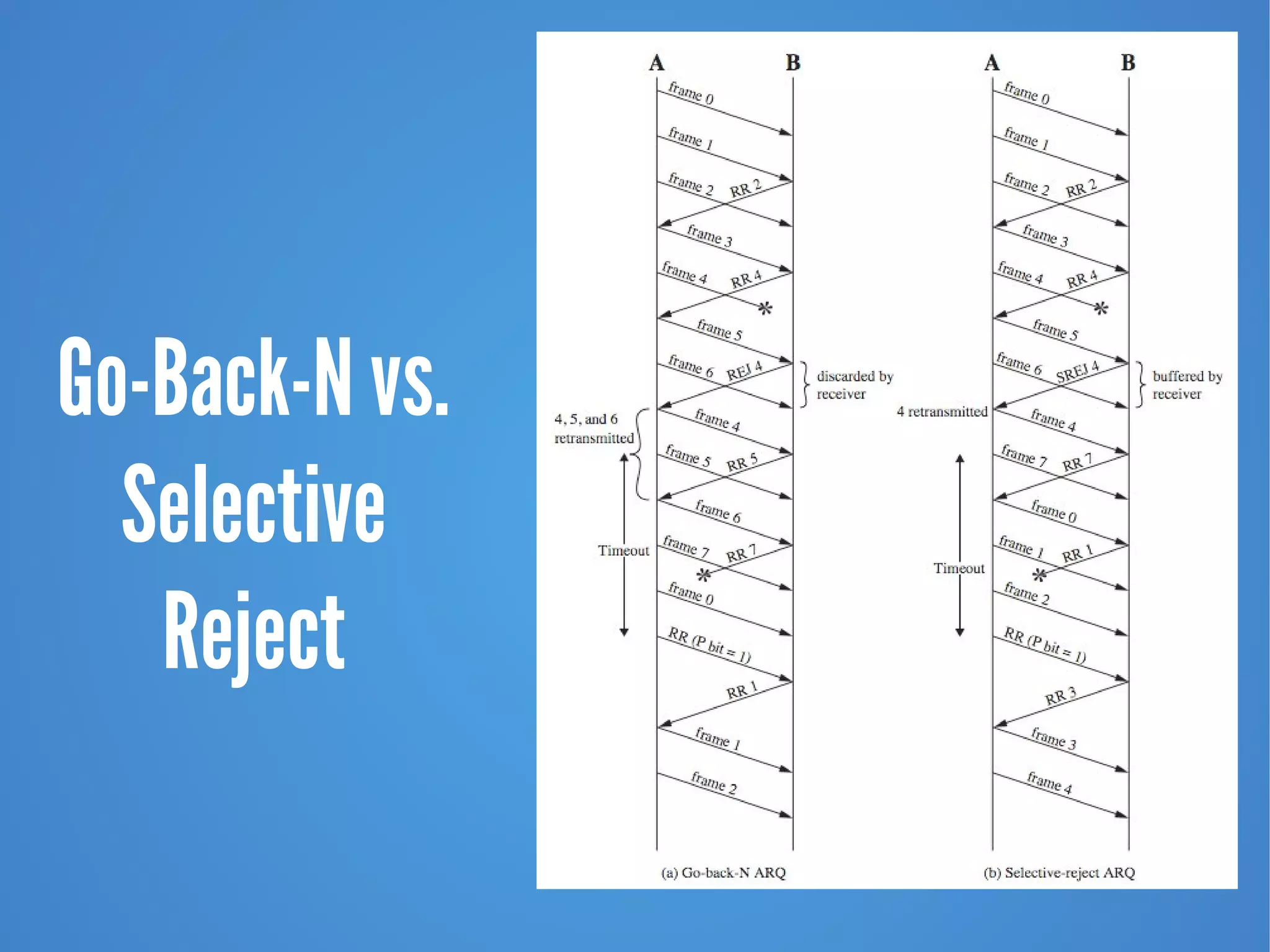
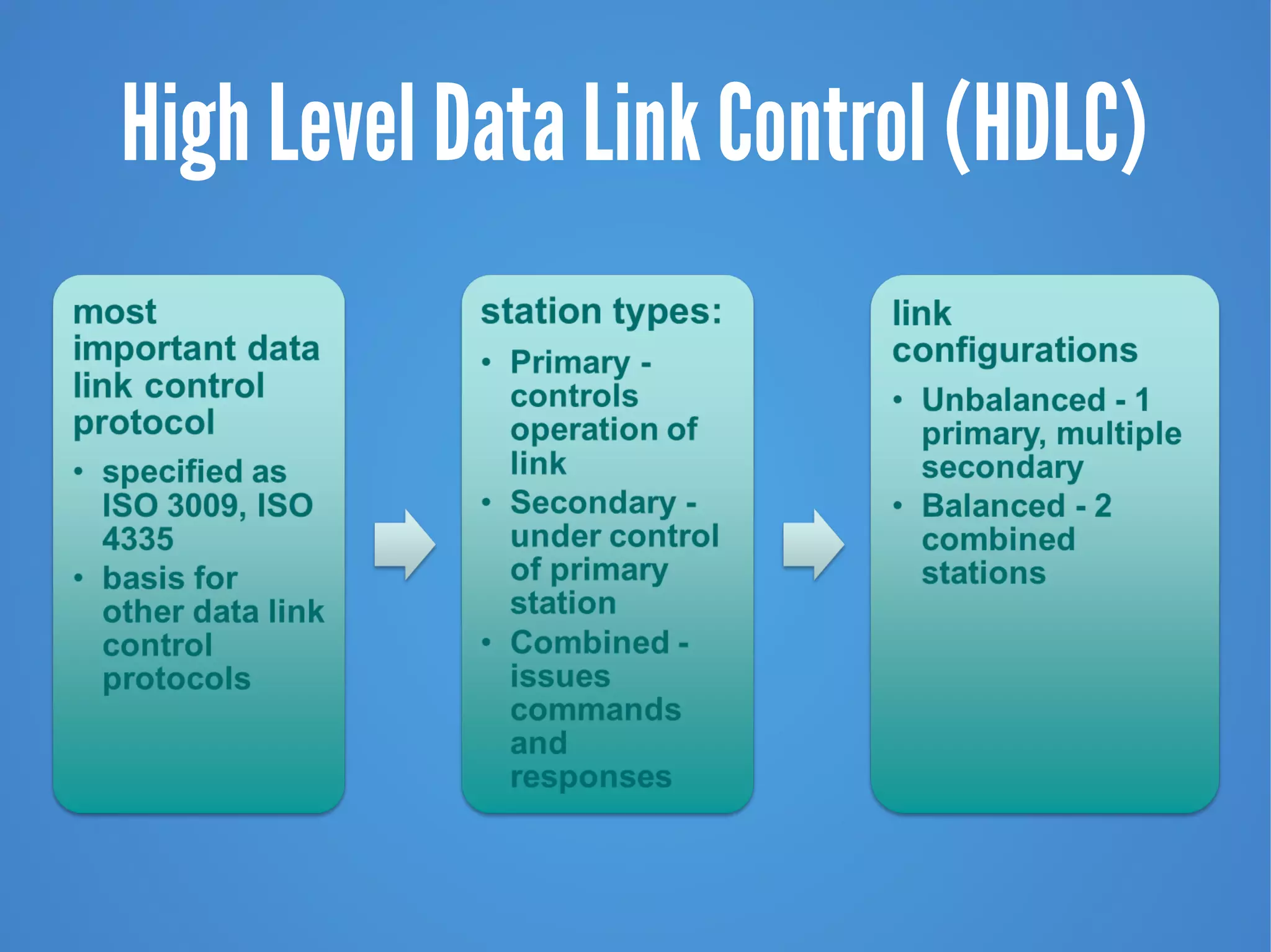
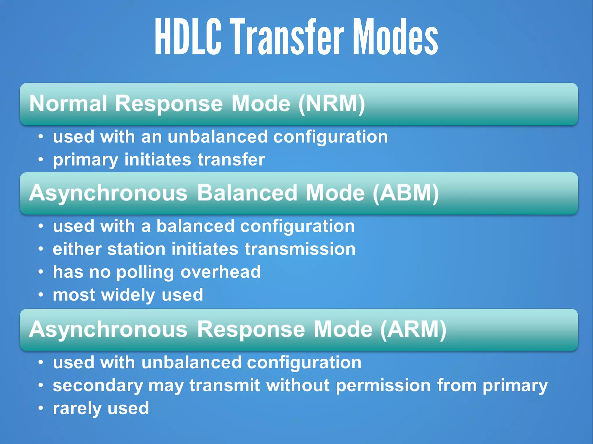
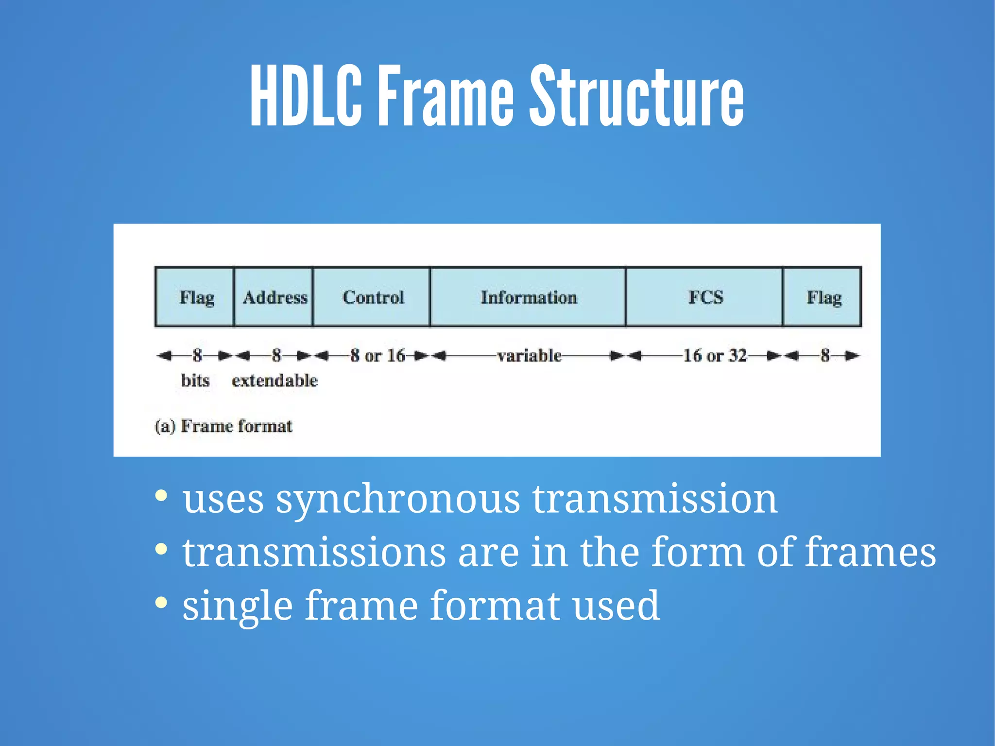
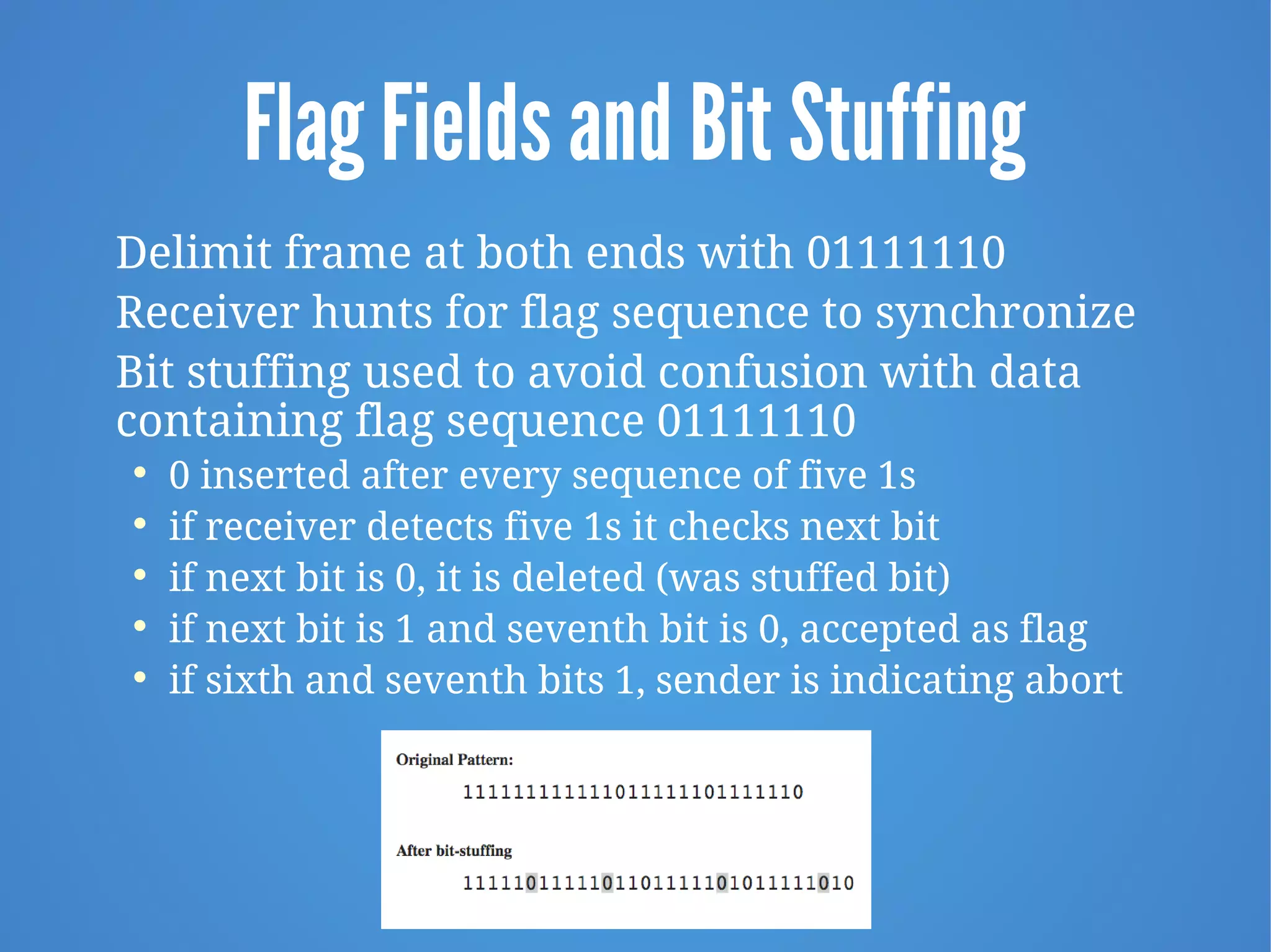
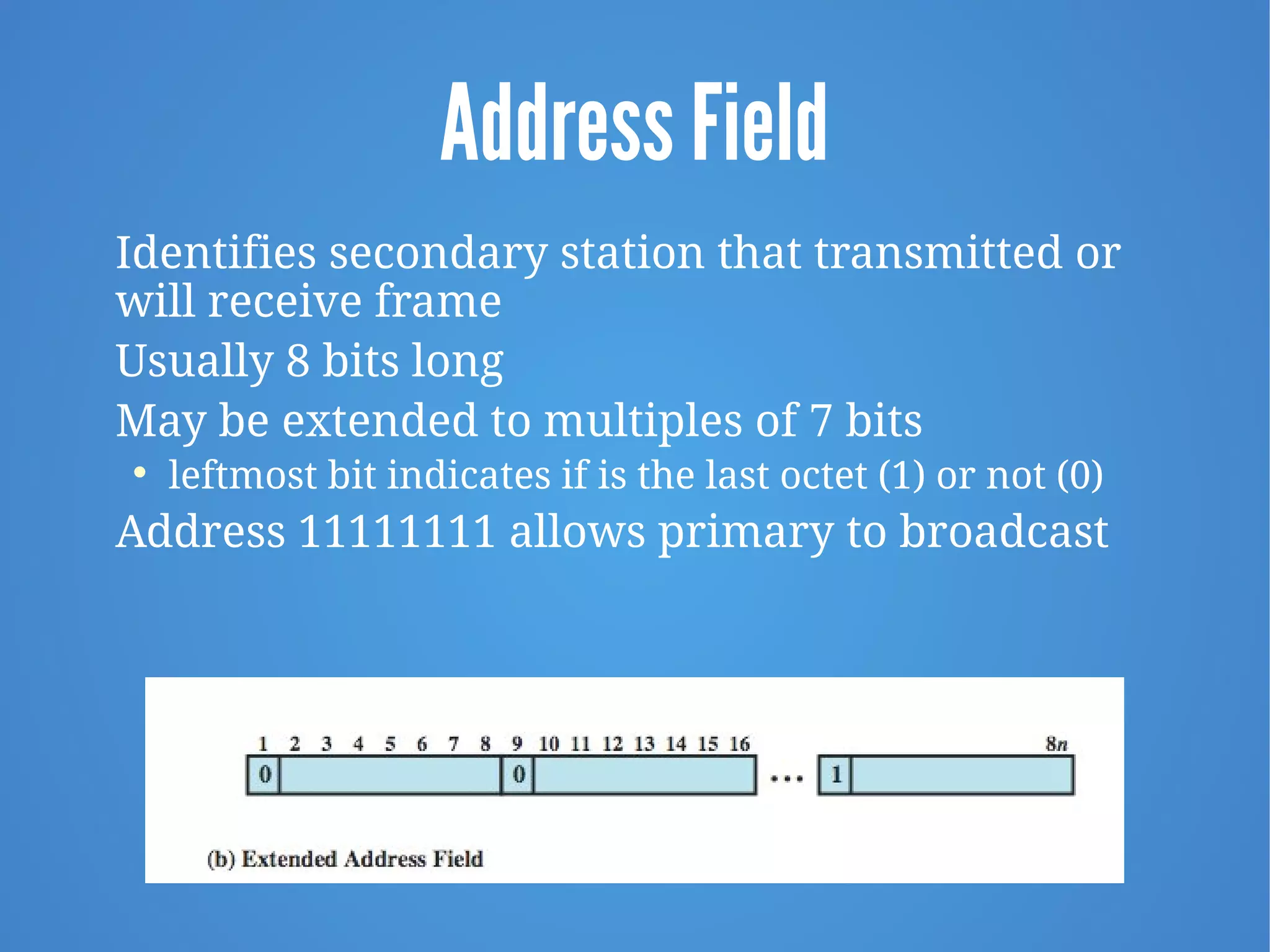
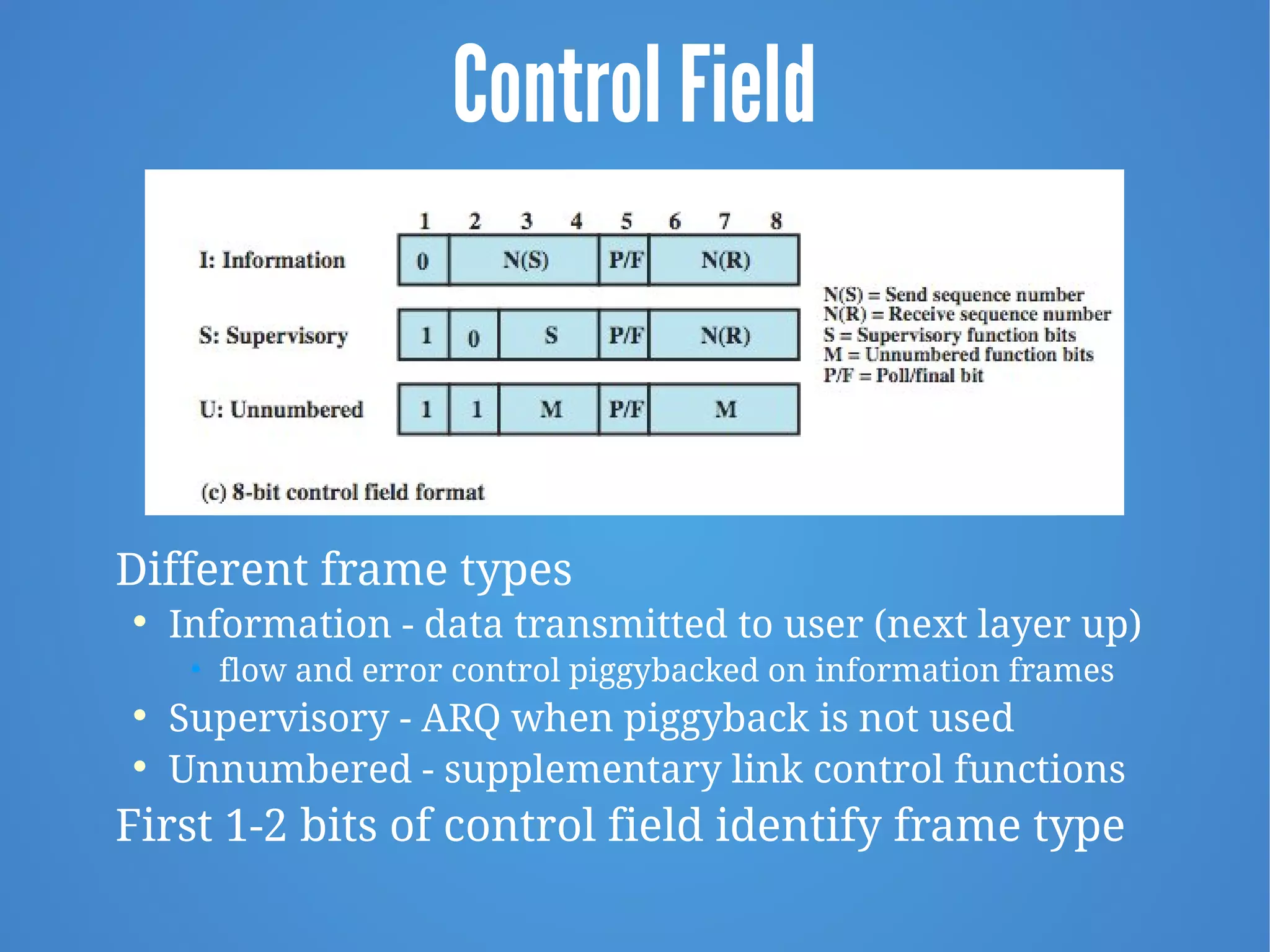
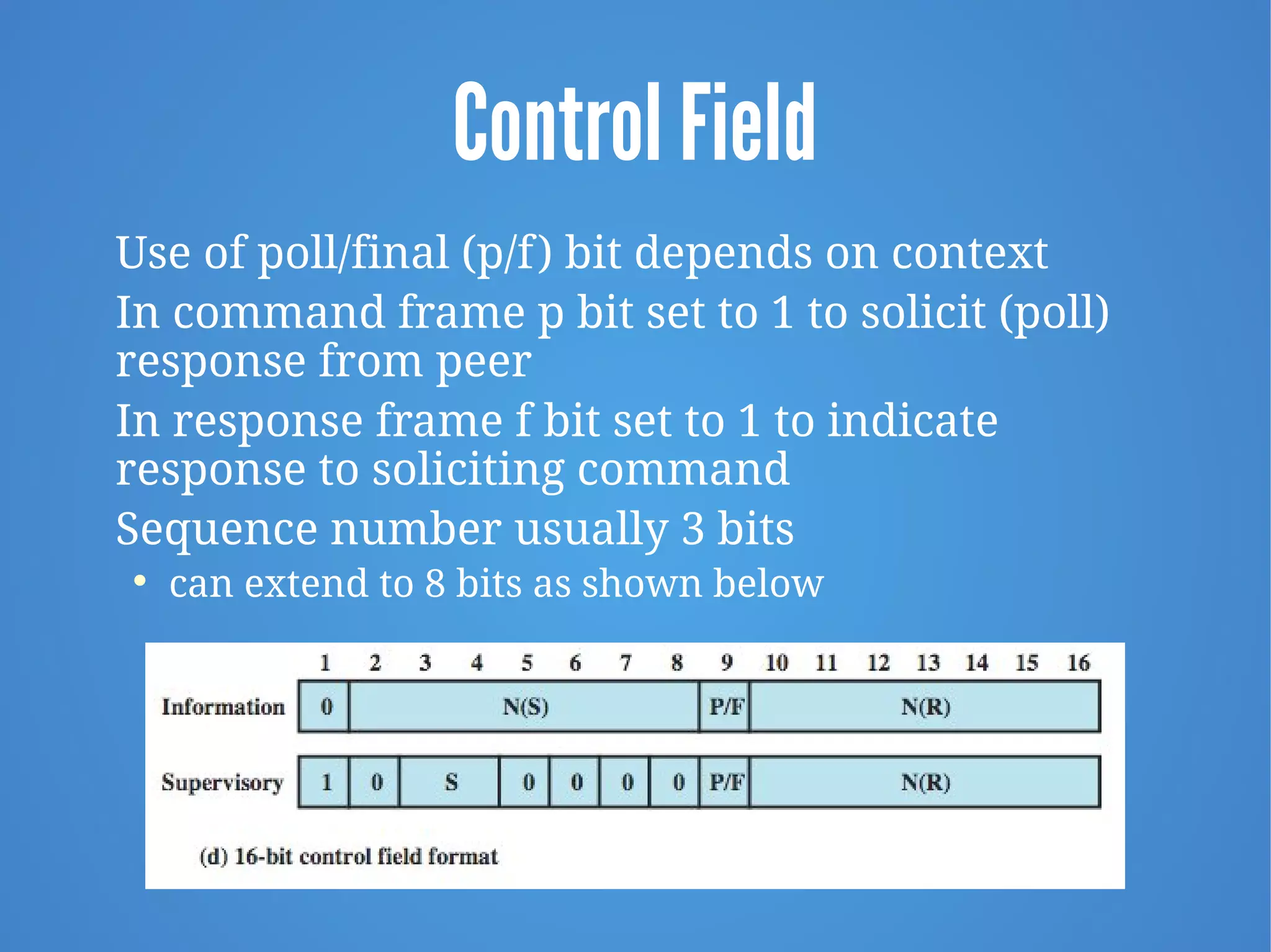
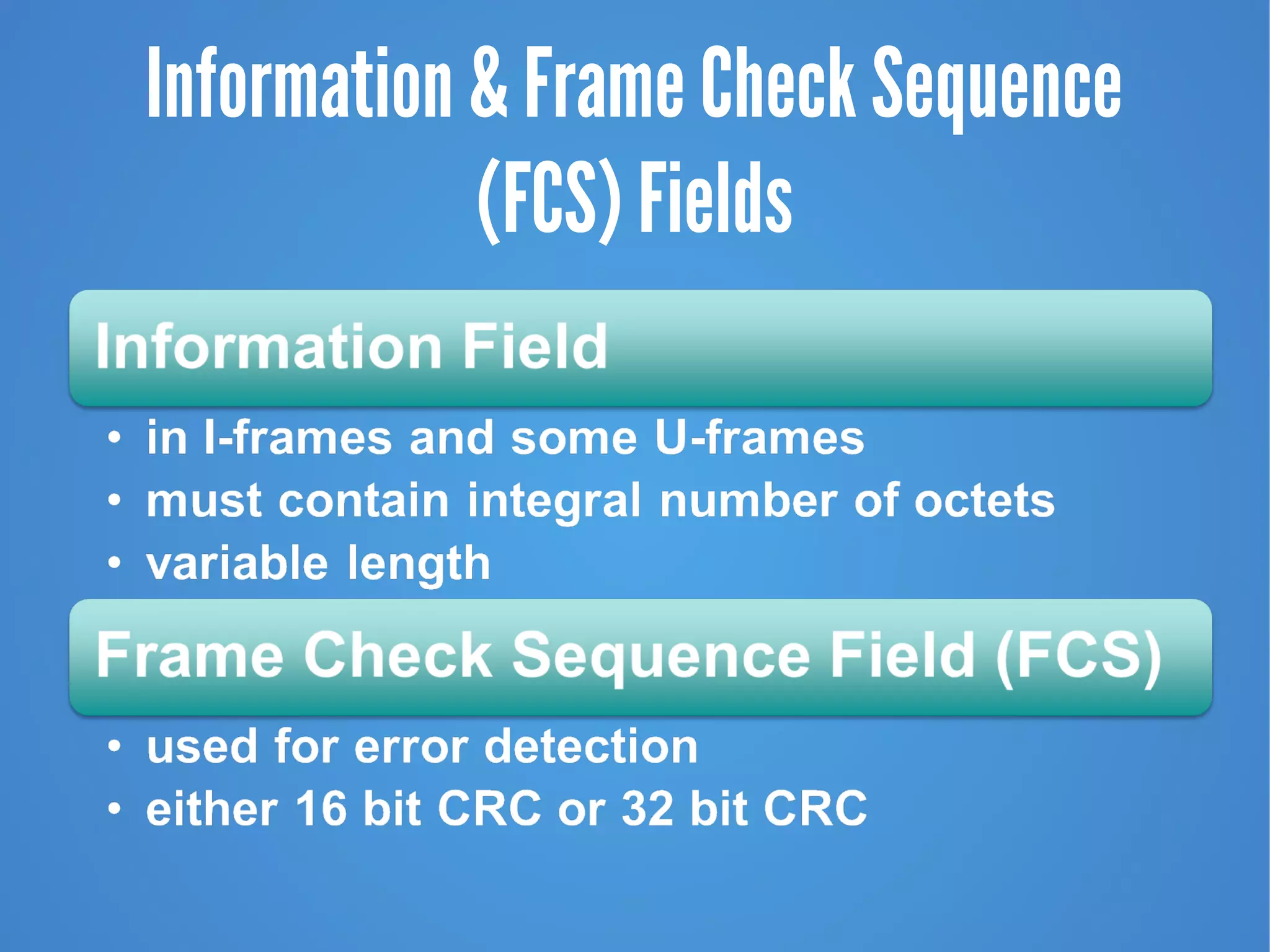
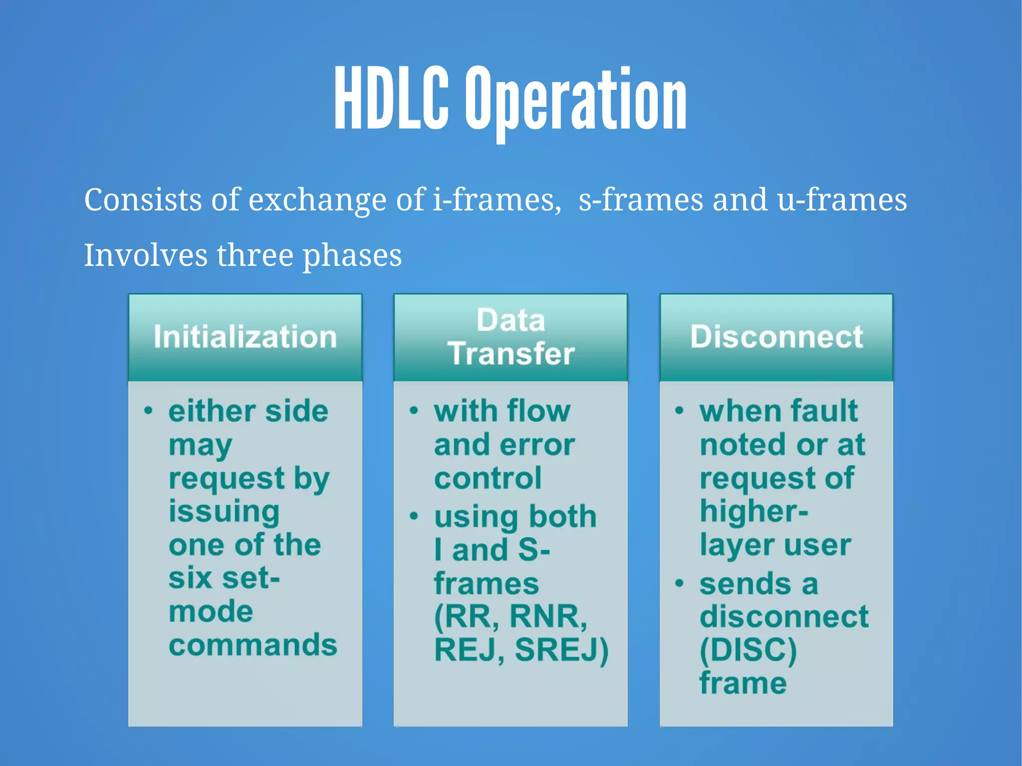
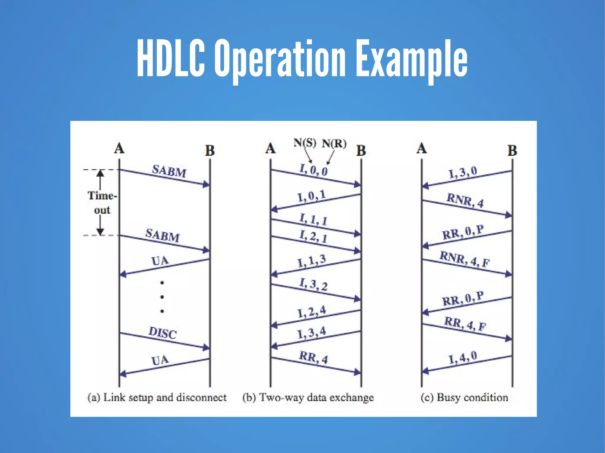
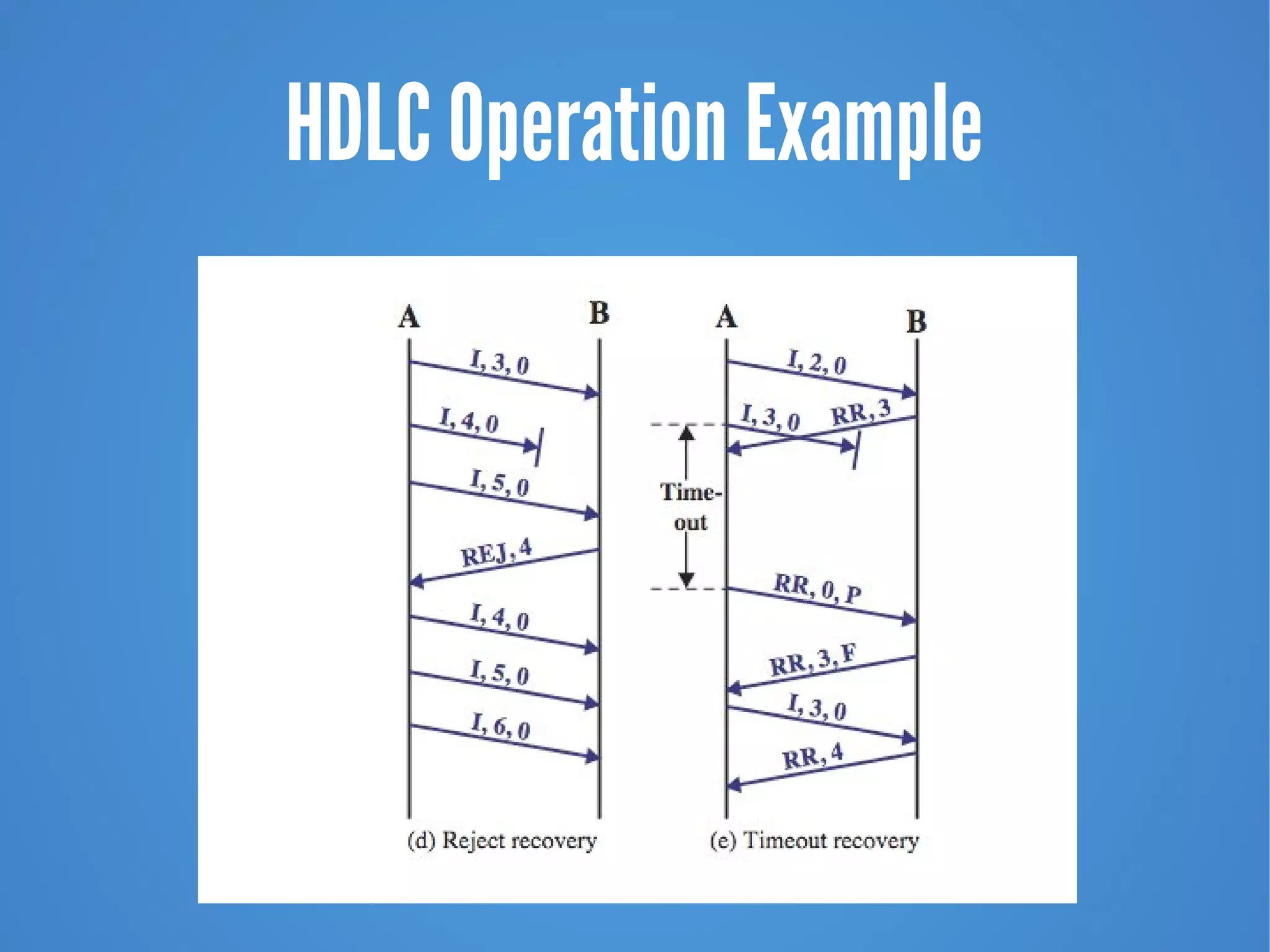
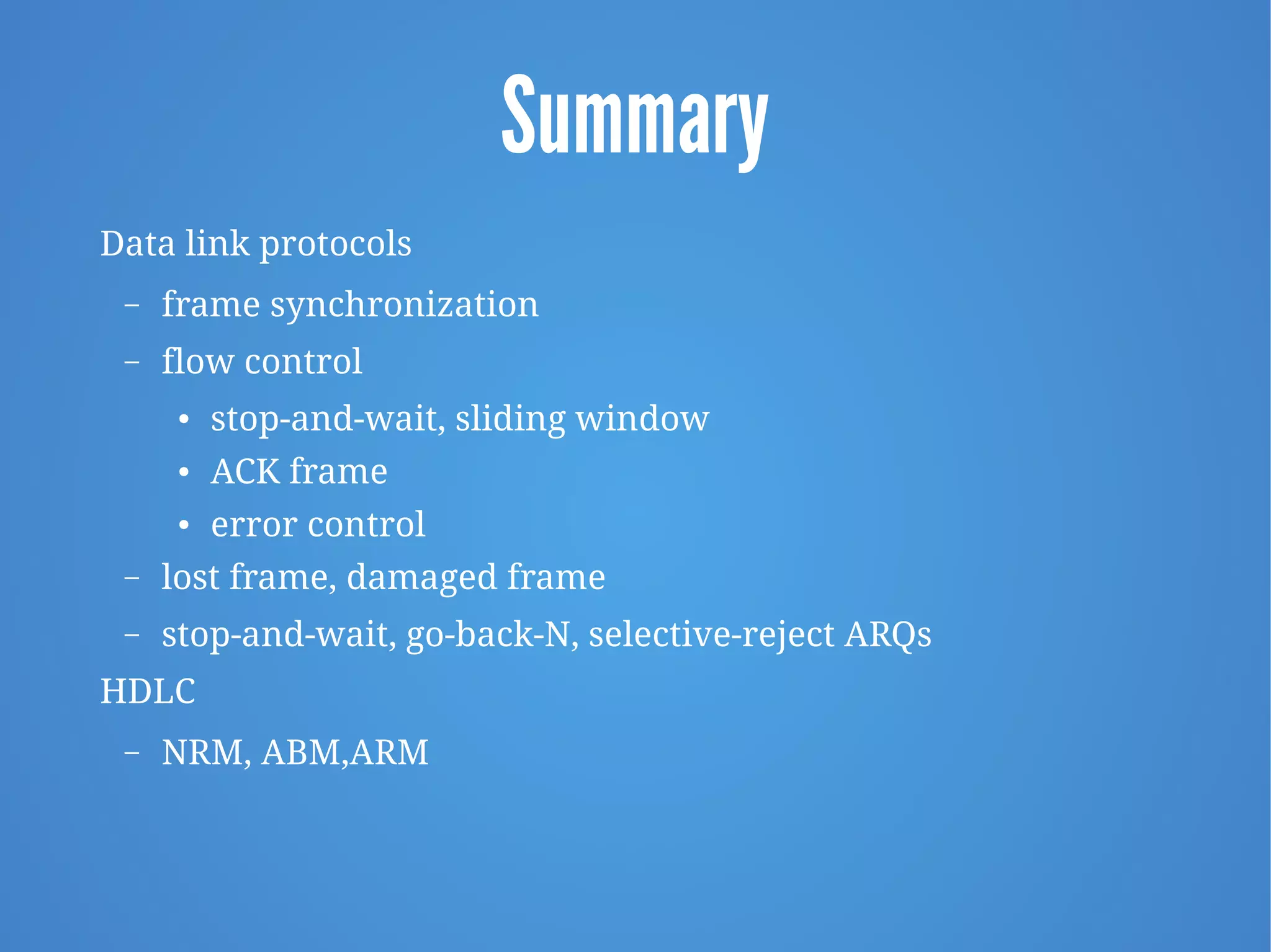
Data Link Control Protocols
CEN 220/CIS 192 Advanced Data Communications and Networking
Data and Computer Communications, W. Stallings 9/E, Chapter 7
Data Link Control Protocols
“Great and enlightened one,” said Ten-teh, as soon as his
stupor was lifted, “has this person delivered his message
competently, for his mind was still a seared vision of snow
and sand and perchance his tongue has stumbled?”
“Bend your ears to the wall,” replied the Emperor, “and be
assured.”
—Kai Lung's Golden Hours,
Earnest Bramah
Data Link Control Protocols
When sending data, to achieve control, a layer of
logic is added above the physical layer

data link control or a data link control protocol
To manage exchange of data over a link:

frame synchronization

flow control

error control

addressing

control and data

link management
Flow Control
Ensure sending entity does not overwhelm receiving entity

prevent buffer overflow
Influenced by:

transmission time
• time taken to emit all bits into medium

propagation time
• time for a bit to traverse the link
Assumption is all frames are successfully received with no
frames lost or arriving with errors
Model of Frame Transmission
Stop and Wait
Simplest form of flow
control
Works well for a
message sent in a few
large frames

stop and wait becomes
inadequate if large
block of data is split
into small frames by
source
Stop and Wait Link Utilization
Sliding Windows Flow Control
Allows multiple numbered frames to be in transit

receiver has buffer W long

transmitter sends up to W frames without ACK

ACK includes number of next frame expected

sequence number is bounded by size of field (k)
• frames are numbered modulo 2k
• giving max window size of up to 2k – 1

receiver can ACK frames without permitting further
transmission (Receive Not Ready)

must send a normal acknowledge to resume
If have full-duplex link, can piggyback acks
Sliding Window Diagram
Sliding Window Example
Error Control Techniques
Detection and
correction of errors
such as:
lost frames
-a frame fails
to arrive at
the other side
damaged frames
-frame arrives
but some of
the bits are in
error
Automatic Repeat Request (ARQ)
Collective name for error control mechanisms
Effect of arq is to turn an unreliable data link into a
reliable one
Versions of arq are:

stop-and-wait

go-back-N

selective-reject
Stop and Wait ARQ
Source transmits single frame
Waits for ack
• no other data can be sent until destination’s reply arrives
If frame received is damaged, discard it
 transmitter has timeout
 if no ACK within timeout, retransmit
If ack is damaged, transmitter will not recognize
 transmitter will retransmit
 receiver gets two copies of frame
 use alternate numbering and ACK0 / ACK1
Stop and Wait ARQ
Go-Back-N ARQ
Most commonly used error control
Based on sliding-window
Use window size to control number of outstanding frames
If no error, ack as usual
If error, reply with rejection

destination will discard that frame and all future
frames until frame in error is received correctly

transmitter must go back and retransmit that frame
and all subsequent frames
Go Back N - Handling
Damaged frame

error in frame i so receiver rejects frame i

transmitter retransmits frames from i
Lost frame

frame i lost and either
• transmitter sends i+1 and receiver gets frame i+1 out
of sequence and rejects frame i
• or transmitter times out and sends ACK with P bit set
which receiver responds to with ACK i

transmitter then retransmits frames from i
Go Back N - Handling
Selective-Reject (ARQ)
Also called selective retransmission
Only rejected frames are retransmitted
Subsequent frames are accepted by the receiver
and buffered
Minimizes retransmission
Receiver must maintain large enough buffer
More complex logic in transmitter

less widely used
Useful for satellite links with long propagation
delays
Go-Back-N vs.
Selective
Reject
High Level Data Link Control (HDLC)
HDLC Transfer Modes
HDLC Frame Structure

uses synchronous transmission

transmissions are in the form of frames

single frame format used
Flag Fields and Bit Stuffing
Delimit frame at both ends with 01111110
Receiver hunts for flag sequence to synchronize
Bit stuffing used to avoid confusion with data
containing flag sequence 01111110

0 inserted after every sequence of five 1s

if receiver detects five 1s it checks next bit

if next bit is 0, it is deleted (was stuffed bit)

if next bit is 1 and seventh bit is 0, accepted as flag

if sixth and seventh bits 1, sender is indicating abort
Address Field
Identifies secondary station that transmitted or
will receive frame
Usually 8 bits long
May be extended to multiples of 7 bits

leftmost bit indicates if is the last octet (1) or not (0)
Address 11111111 allows primary to broadcast
Control Field
Different frame types

Information - data transmitted to user (next layer up)
• flow and error control piggybacked on information frames

Supervisory - ARQ when piggyback is not used

Unnumbered - supplementary link control functions
First 1-2 bits of control field identify frame type
Control Field
Use of poll/final (p/f) bit depends on context
In command frame p bit set to 1 to solicit (poll)
response from peer
In response frame f bit set to 1 to indicate
response to soliciting command
Sequence number usually 3 bits

can extend to 8 bits as shown below
Information & Frame Check Sequence
(FCS) Fields
HDLC Operation
Consists of exchange of i-frames, s-frames and u-frames
Involves three phases
HDLC Operation Example
Summary
Data link protocols
– frame synchronization
– flow control
● stop-and-wait, sliding window
● ACK frame
● error control
– lost frame, damaged frame
– stop-and-wait, go-back-N, selective-reject ARQs
HDLC
– NRM, ABM,ARM

Chapter 7 - Data Link Control Protocols 9e

  • 1.
    Data Link ControlProtocols CEN 220/CIS 192 Advanced Data Communications and Networking Data and Computer Communications, W. Stallings 9/E, Chapter 7
  • 2.
    Data Link ControlProtocols “Great and enlightened one,” said Ten-teh, as soon as his stupor was lifted, “has this person delivered his message competently, for his mind was still a seared vision of snow and sand and perchance his tongue has stumbled?” “Bend your ears to the wall,” replied the Emperor, “and be assured.” —Kai Lung's Golden Hours, Earnest Bramah
  • 3.
    Data Link ControlProtocols When sending data, to achieve control, a layer of logic is added above the physical layer  data link control or a data link control protocol To manage exchange of data over a link:  frame synchronization  flow control  error control  addressing  control and data  link management
  • 4.
    Flow Control Ensure sendingentity does not overwhelm receiving entity  prevent buffer overflow Influenced by:  transmission time • time taken to emit all bits into medium  propagation time • time for a bit to traverse the link Assumption is all frames are successfully received with no frames lost or arriving with errors
  • 5.
    Model of FrameTransmission
  • 6.
    Stop and Wait Simplestform of flow control Works well for a message sent in a few large frames  stop and wait becomes inadequate if large block of data is split into small frames by source
  • 7.
    Stop and WaitLink Utilization
  • 8.
    Sliding Windows FlowControl Allows multiple numbered frames to be in transit  receiver has buffer W long  transmitter sends up to W frames without ACK  ACK includes number of next frame expected  sequence number is bounded by size of field (k) • frames are numbered modulo 2k • giving max window size of up to 2k – 1  receiver can ACK frames without permitting further transmission (Receive Not Ready)  must send a normal acknowledge to resume If have full-duplex link, can piggyback acks
  • 9.
  • 10.
  • 11.
    Error Control Techniques Detectionand correction of errors such as: lost frames -a frame fails to arrive at the other side damaged frames -frame arrives but some of the bits are in error
  • 12.
    Automatic Repeat Request(ARQ) Collective name for error control mechanisms Effect of arq is to turn an unreliable data link into a reliable one Versions of arq are:  stop-and-wait  go-back-N  selective-reject
  • 13.
    Stop and WaitARQ Source transmits single frame Waits for ack • no other data can be sent until destination’s reply arrives If frame received is damaged, discard it  transmitter has timeout  if no ACK within timeout, retransmit If ack is damaged, transmitter will not recognize  transmitter will retransmit  receiver gets two copies of frame  use alternate numbering and ACK0 / ACK1
  • 14.
  • 15.
    Go-Back-N ARQ Most commonlyused error control Based on sliding-window Use window size to control number of outstanding frames If no error, ack as usual If error, reply with rejection  destination will discard that frame and all future frames until frame in error is received correctly  transmitter must go back and retransmit that frame and all subsequent frames
  • 16.
    Go Back N- Handling Damaged frame  error in frame i so receiver rejects frame i  transmitter retransmits frames from i Lost frame  frame i lost and either • transmitter sends i+1 and receiver gets frame i+1 out of sequence and rejects frame i • or transmitter times out and sends ACK with P bit set which receiver responds to with ACK i  transmitter then retransmits frames from i
  • 17.
    Go Back N- Handling
  • 18.
    Selective-Reject (ARQ) Also calledselective retransmission Only rejected frames are retransmitted Subsequent frames are accepted by the receiver and buffered Minimizes retransmission Receiver must maintain large enough buffer More complex logic in transmitter  less widely used Useful for satellite links with long propagation delays
  • 19.
  • 20.
    High Level DataLink Control (HDLC)
  • 21.
  • 22.
    HDLC Frame Structure  usessynchronous transmission  transmissions are in the form of frames  single frame format used
  • 23.
    Flag Fields andBit Stuffing Delimit frame at both ends with 01111110 Receiver hunts for flag sequence to synchronize Bit stuffing used to avoid confusion with data containing flag sequence 01111110  0 inserted after every sequence of five 1s  if receiver detects five 1s it checks next bit  if next bit is 0, it is deleted (was stuffed bit)  if next bit is 1 and seventh bit is 0, accepted as flag  if sixth and seventh bits 1, sender is indicating abort
  • 24.
    Address Field Identifies secondarystation that transmitted or will receive frame Usually 8 bits long May be extended to multiples of 7 bits  leftmost bit indicates if is the last octet (1) or not (0) Address 11111111 allows primary to broadcast
  • 25.
    Control Field Different frametypes  Information - data transmitted to user (next layer up) • flow and error control piggybacked on information frames  Supervisory - ARQ when piggyback is not used  Unnumbered - supplementary link control functions First 1-2 bits of control field identify frame type
  • 26.
    Control Field Use ofpoll/final (p/f) bit depends on context In command frame p bit set to 1 to solicit (poll) response from peer In response frame f bit set to 1 to indicate response to soliciting command Sequence number usually 3 bits  can extend to 8 bits as shown below
  • 27.
    Information & FrameCheck Sequence (FCS) Fields
  • 28.
    HDLC Operation Consists ofexchange of i-frames, s-frames and u-frames Involves three phases
  • 29.
  • 30.
  • 31.
    Summary Data link protocols –frame synchronization – flow control ● stop-and-wait, sliding window ● ACK frame ● error control – lost frame, damaged frame – stop-and-wait, go-back-N, selective-reject ARQs HDLC – NRM, ABM,ARM