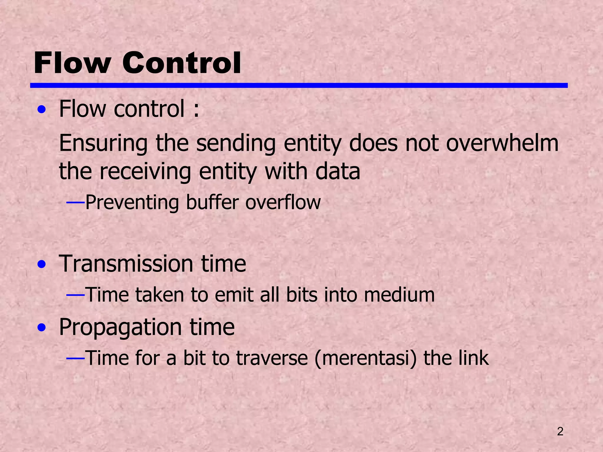
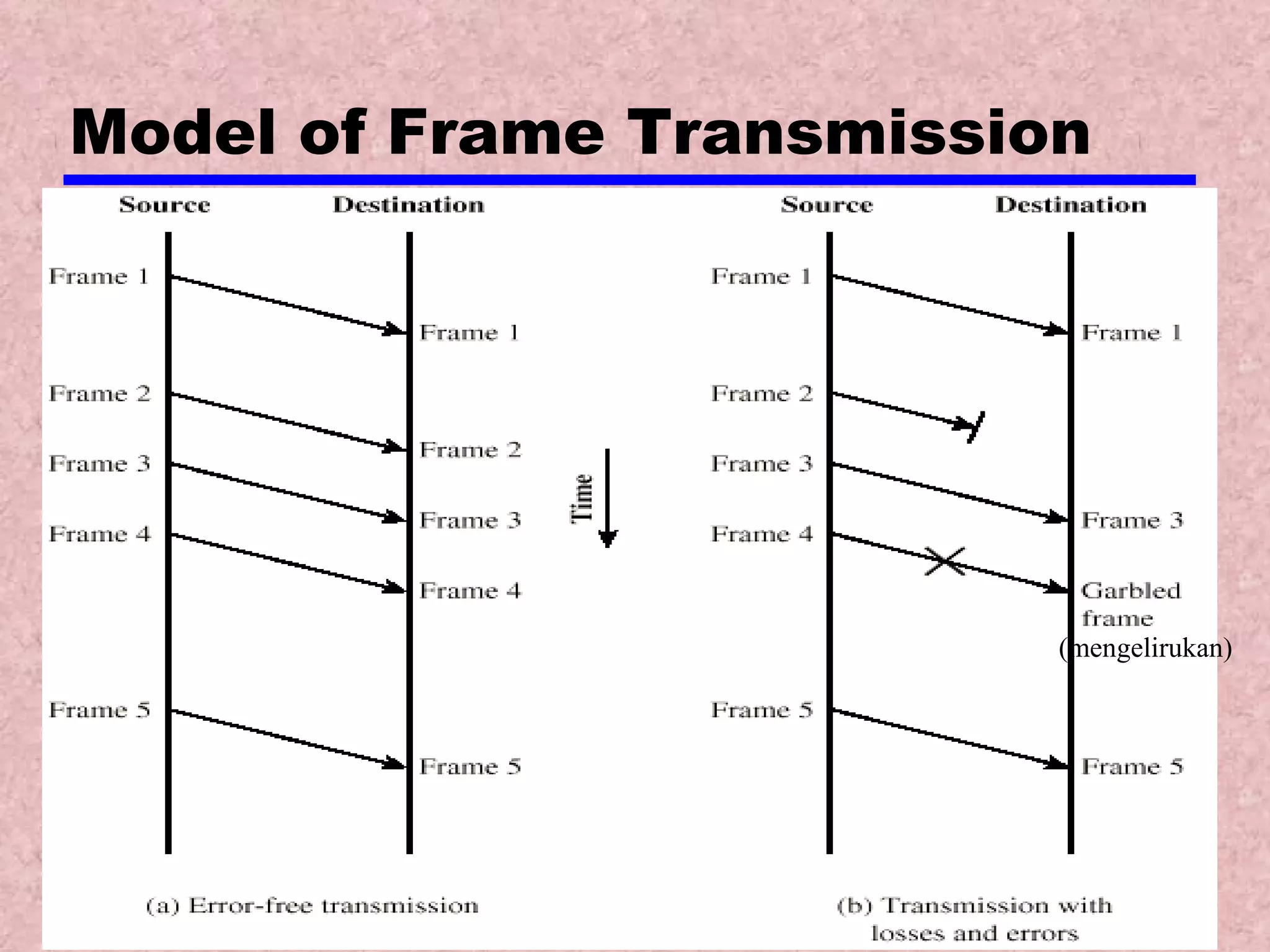
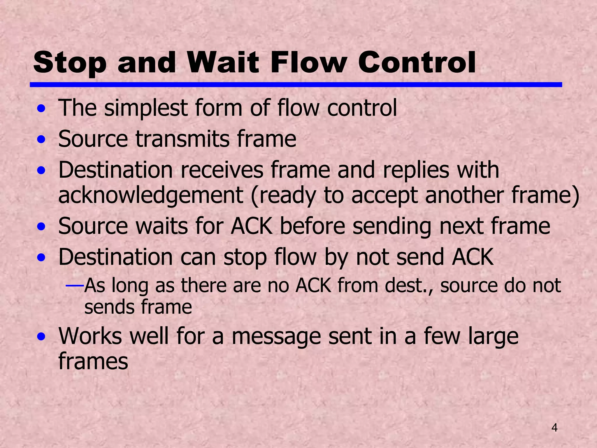
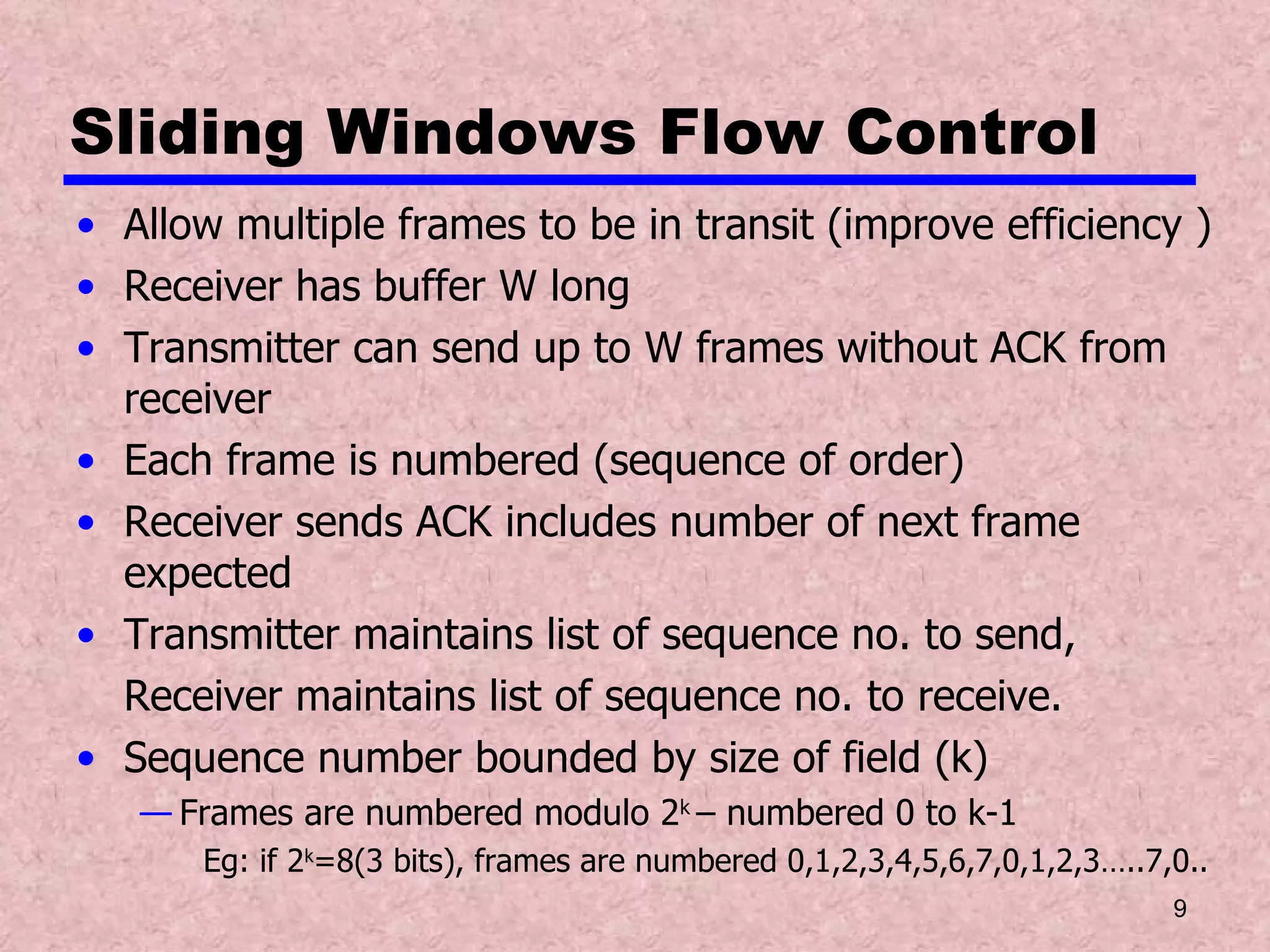
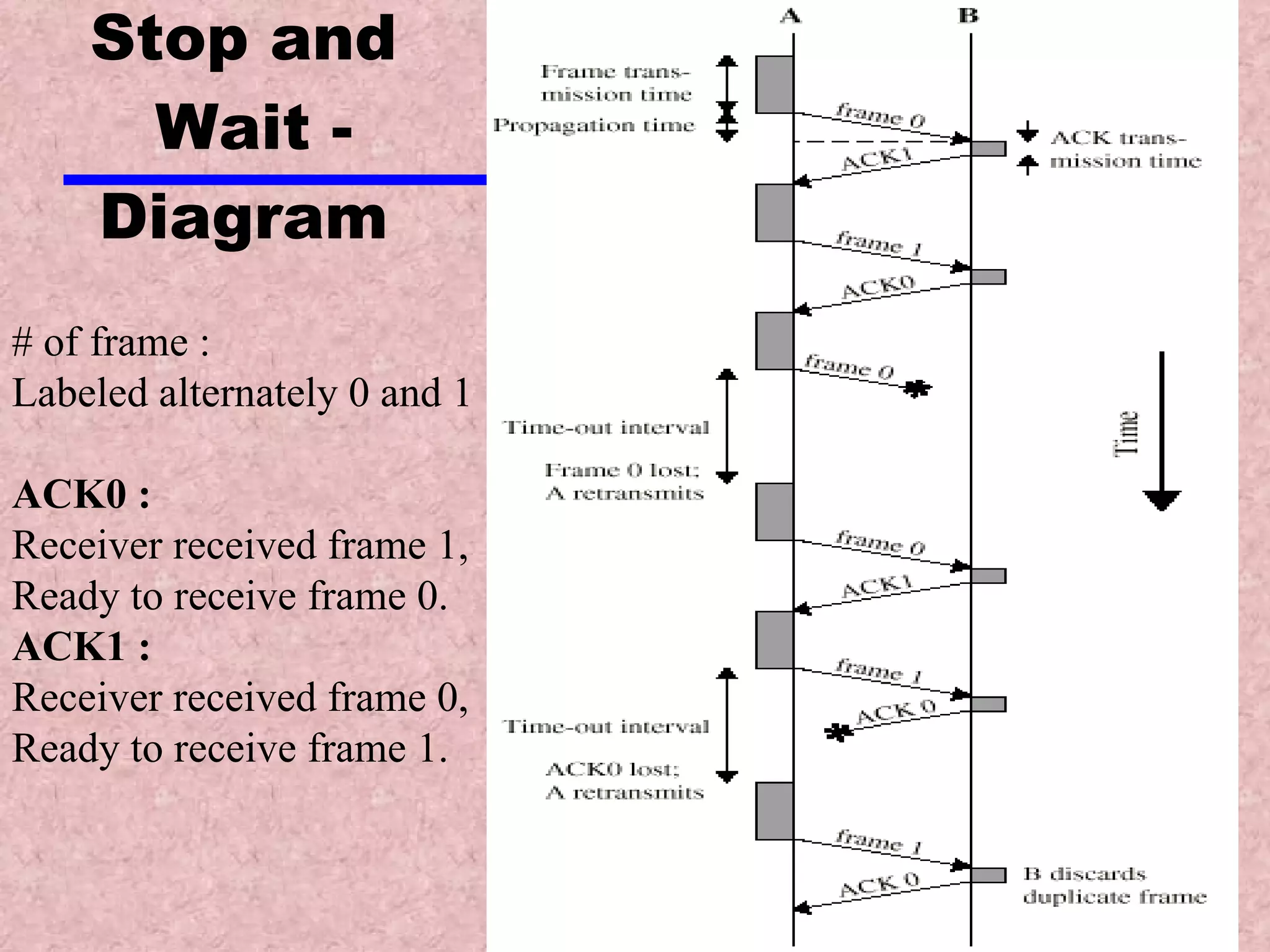
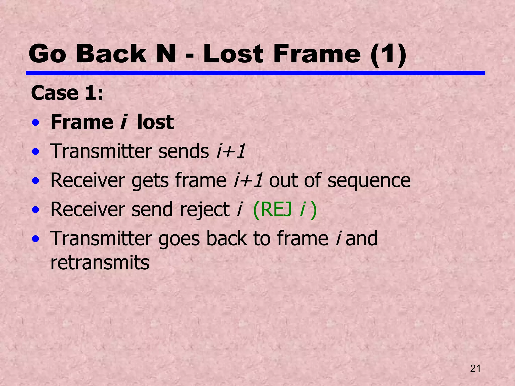
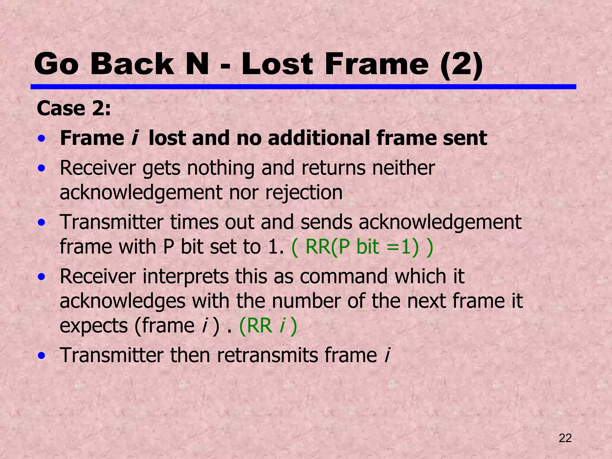
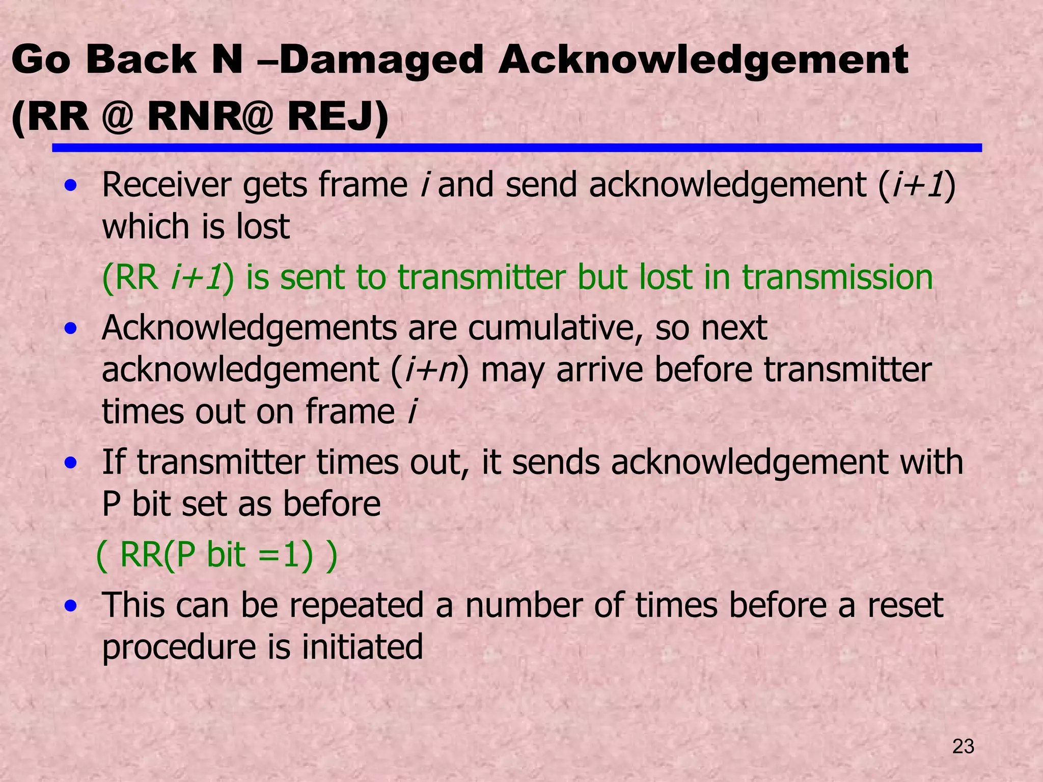
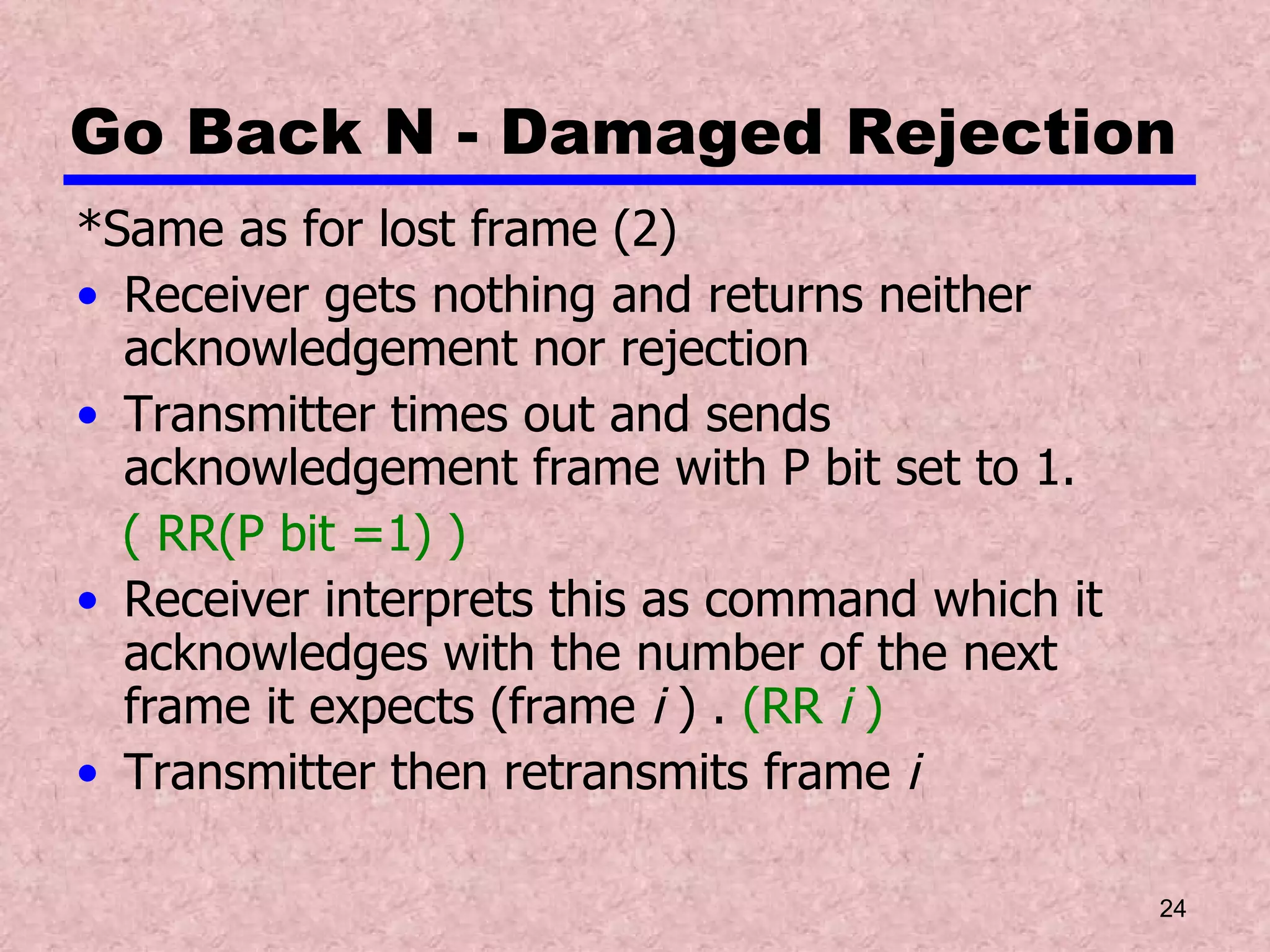
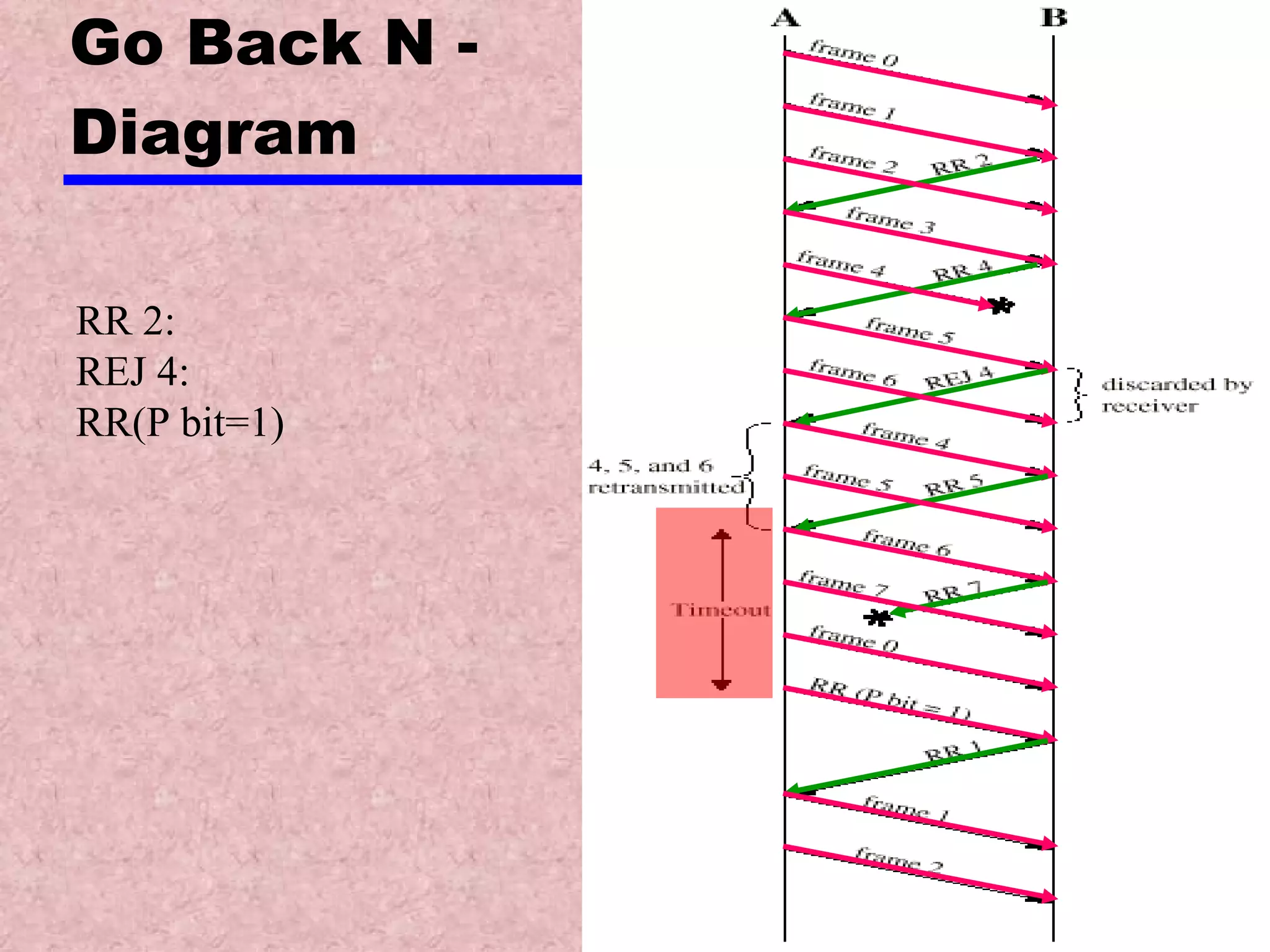
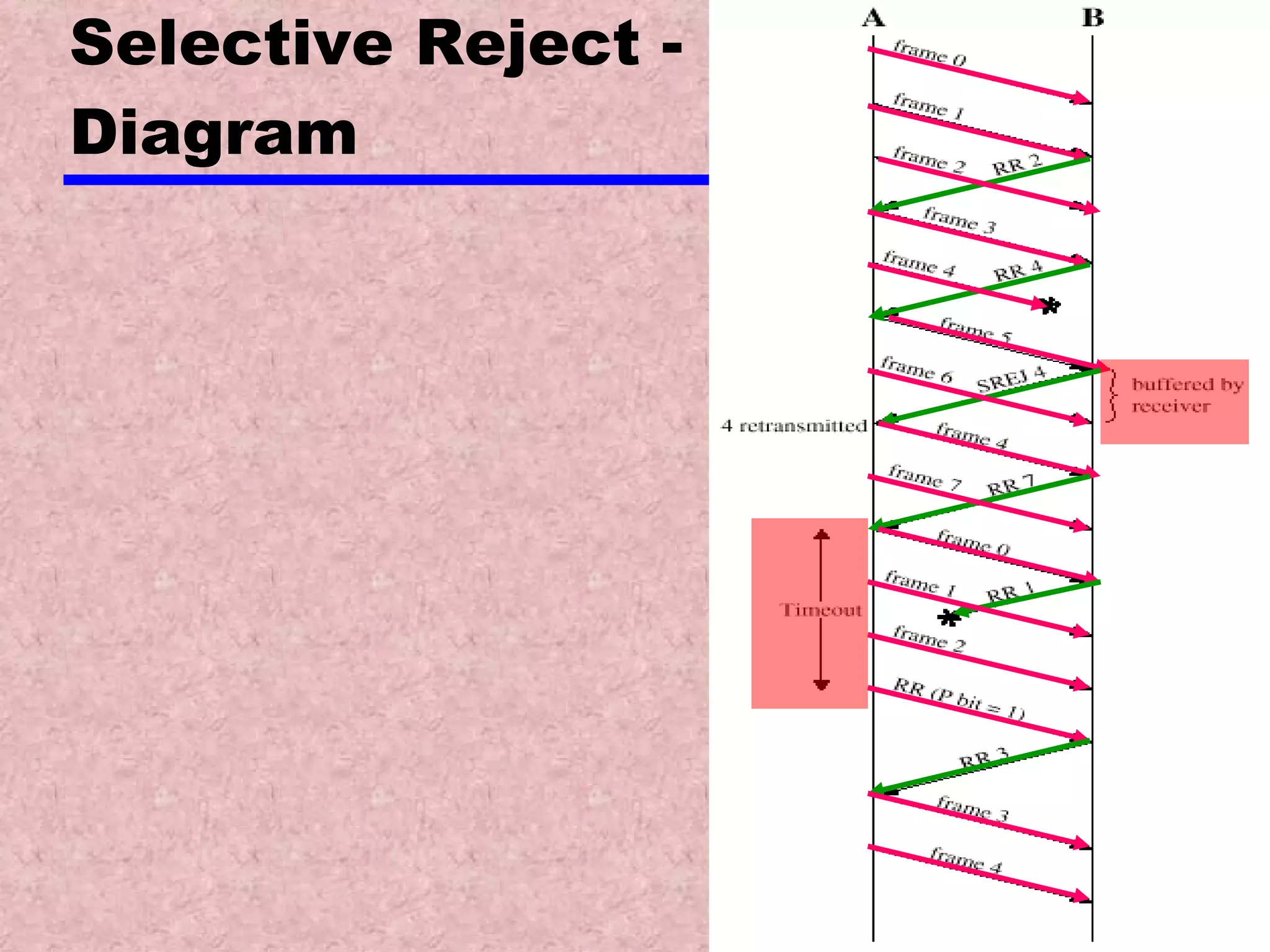
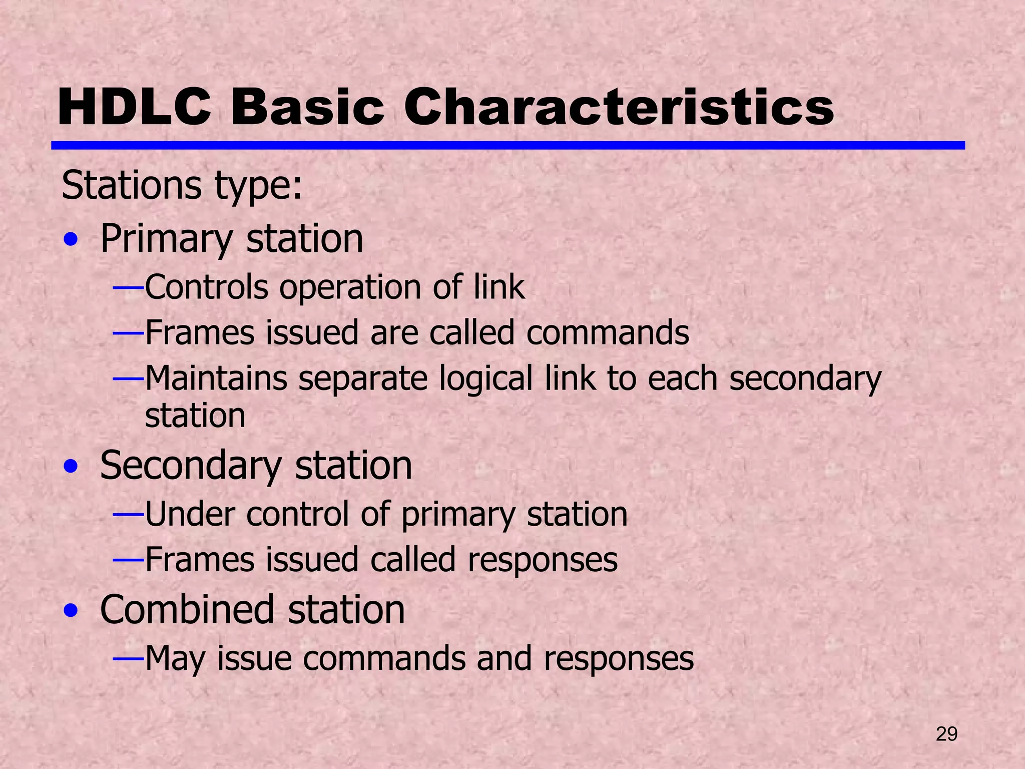
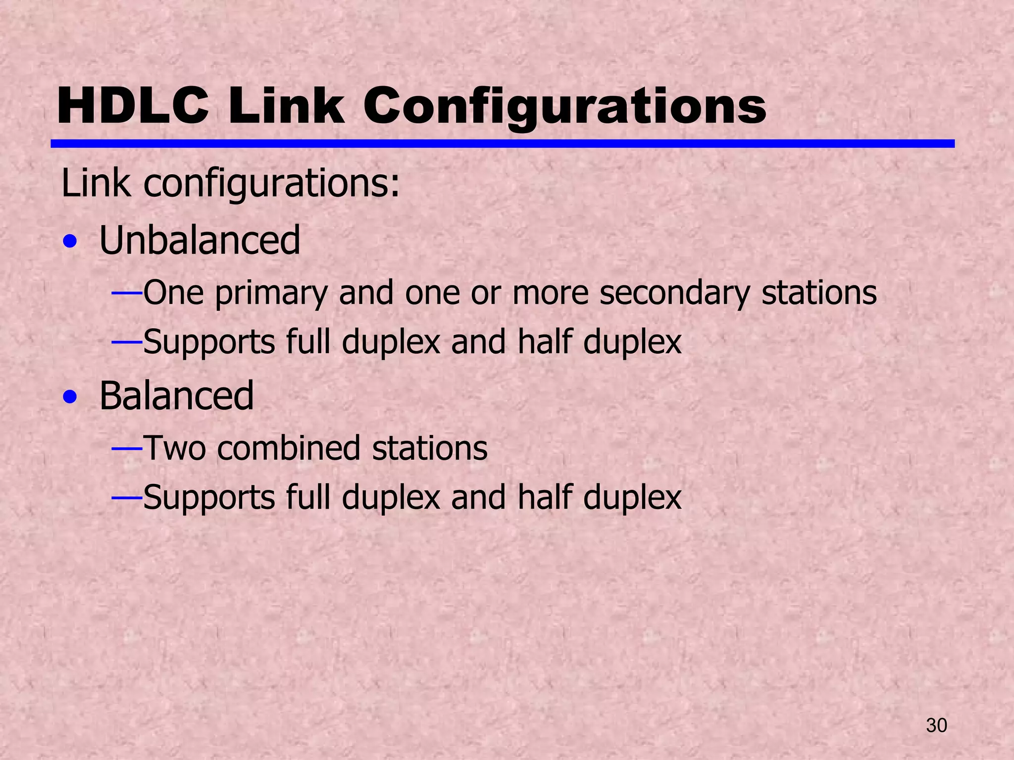
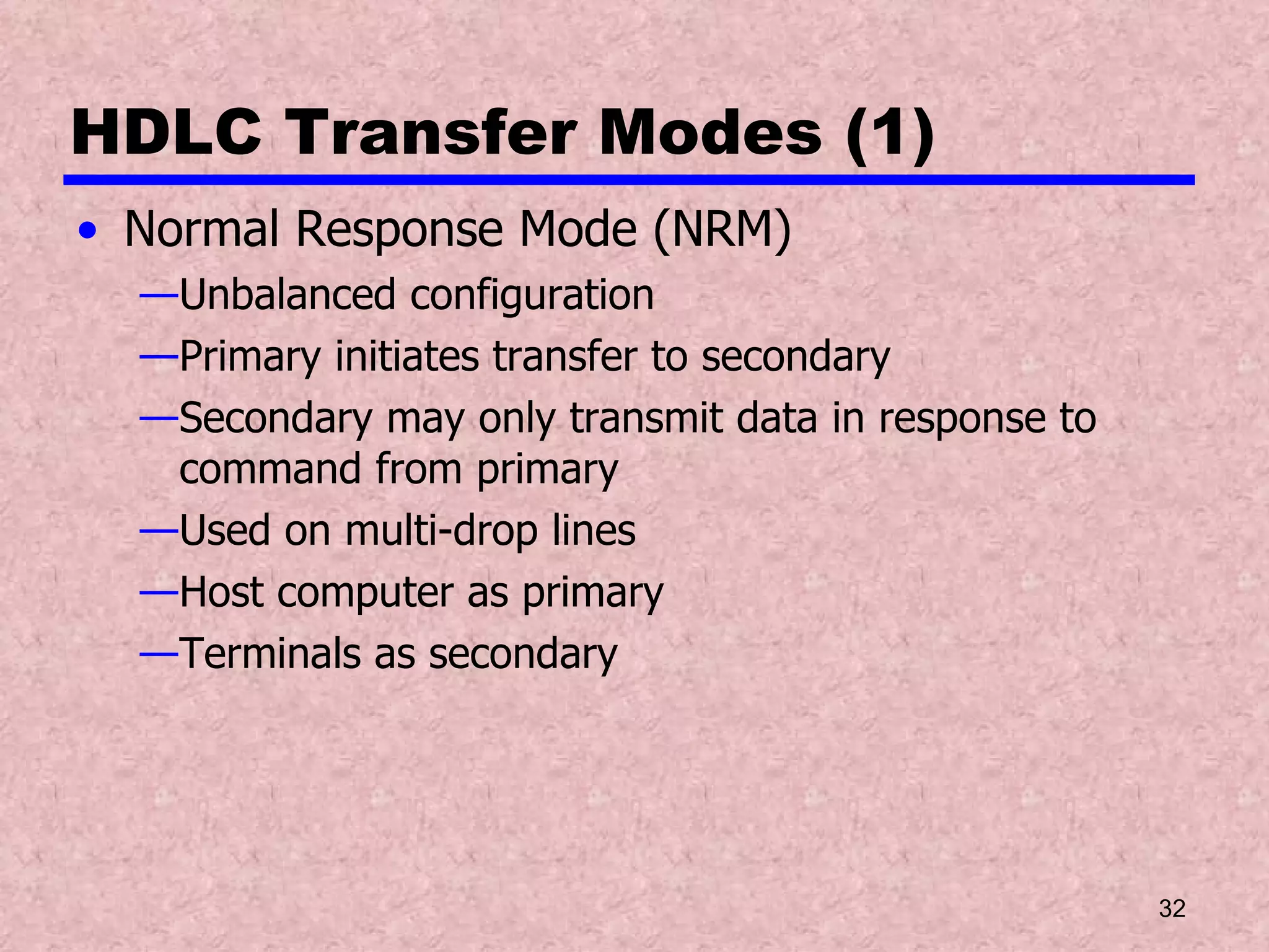
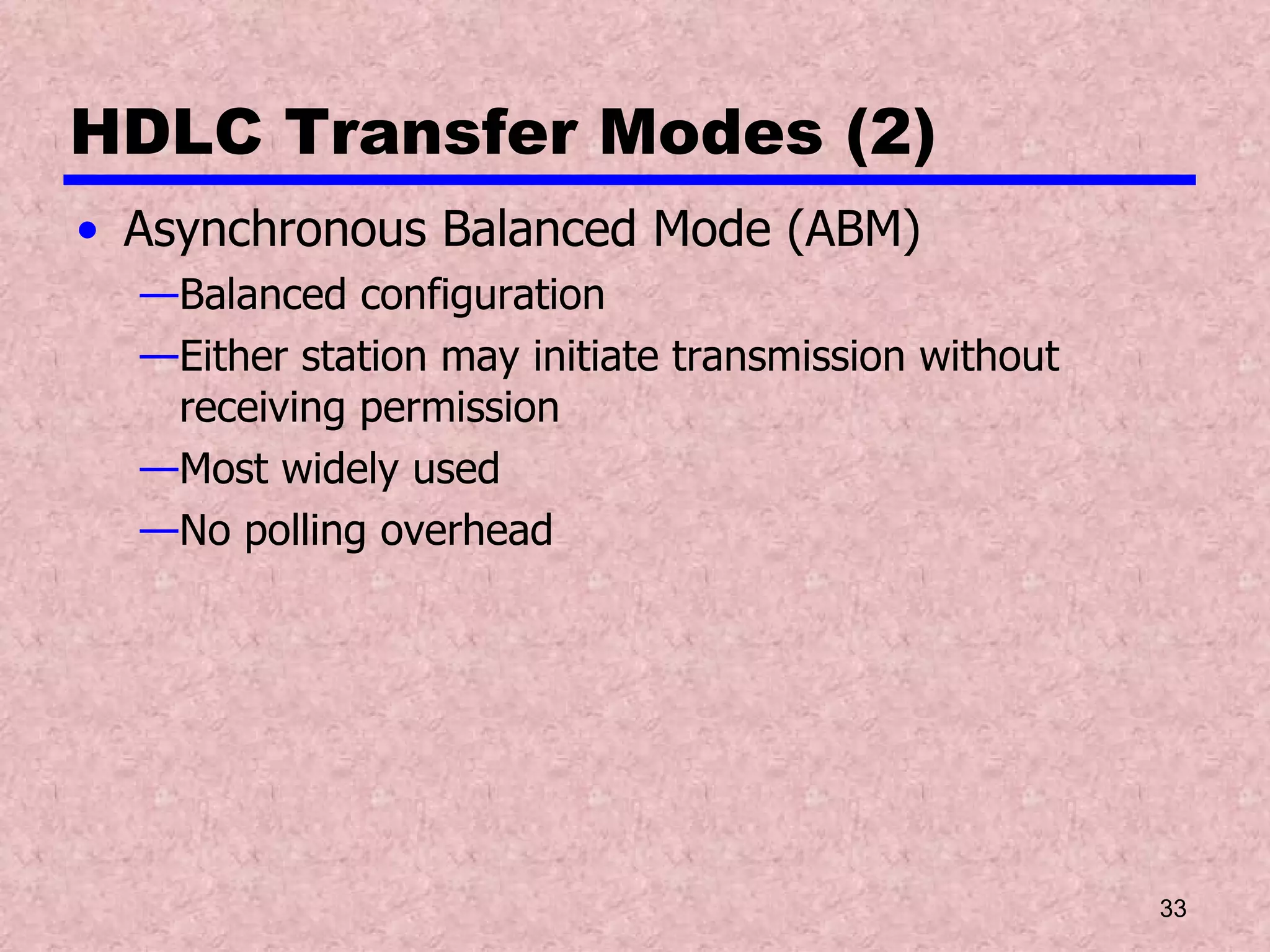
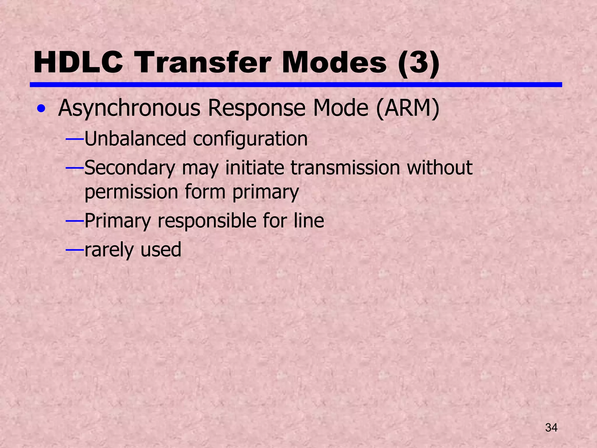
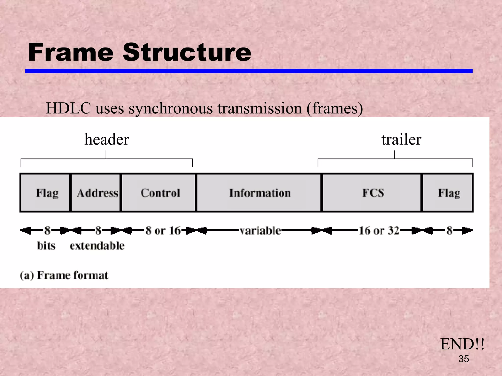
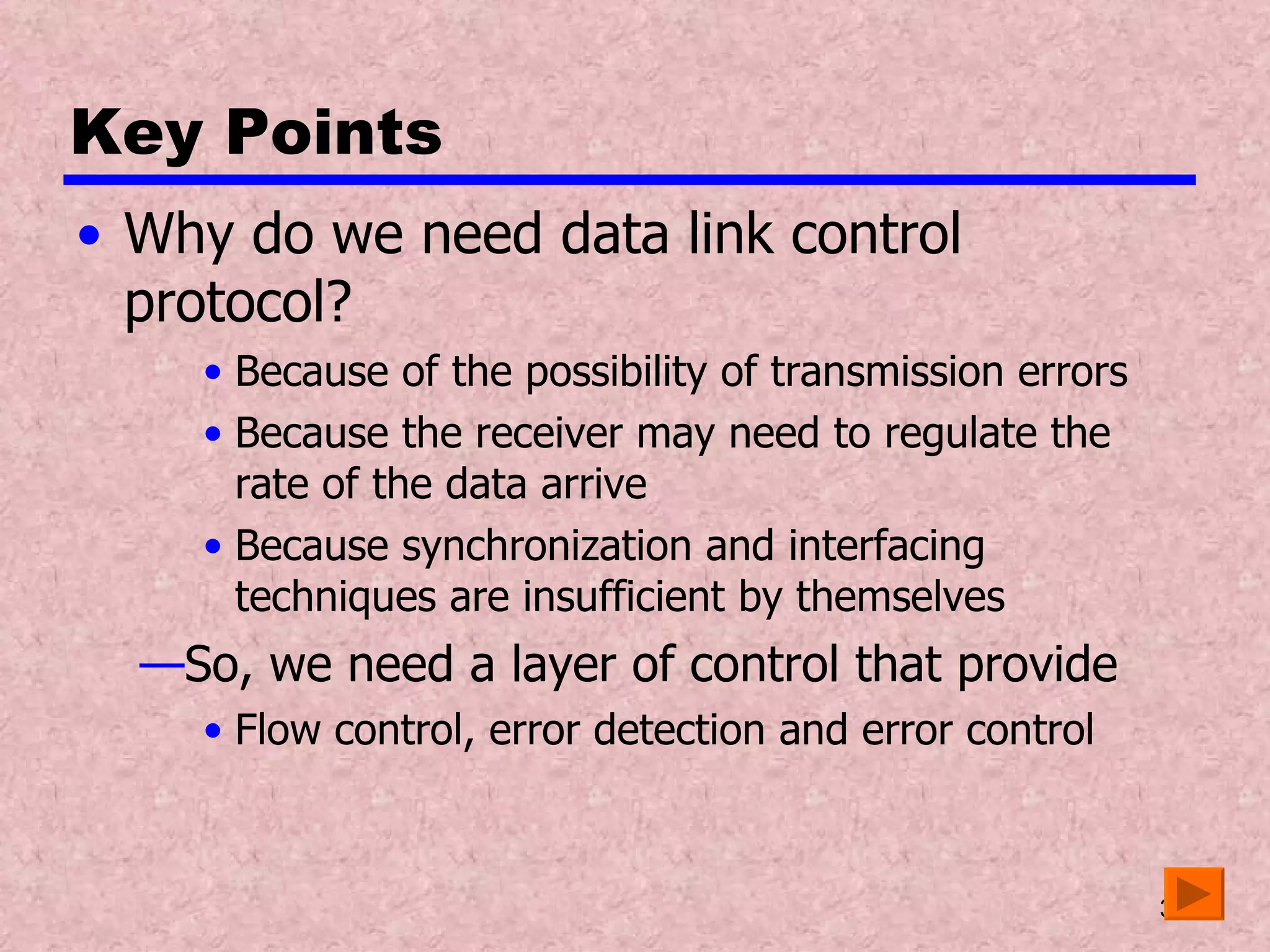
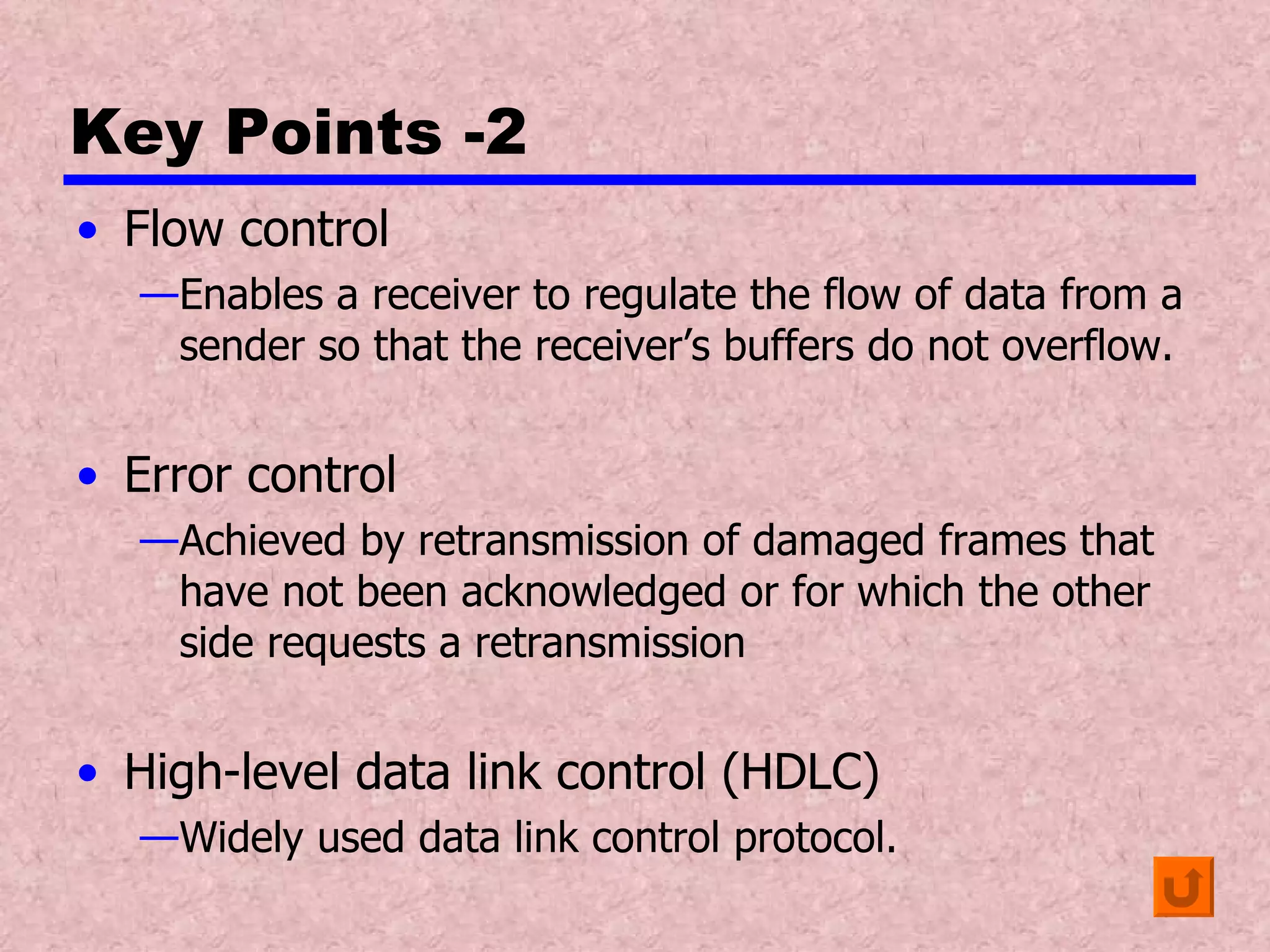
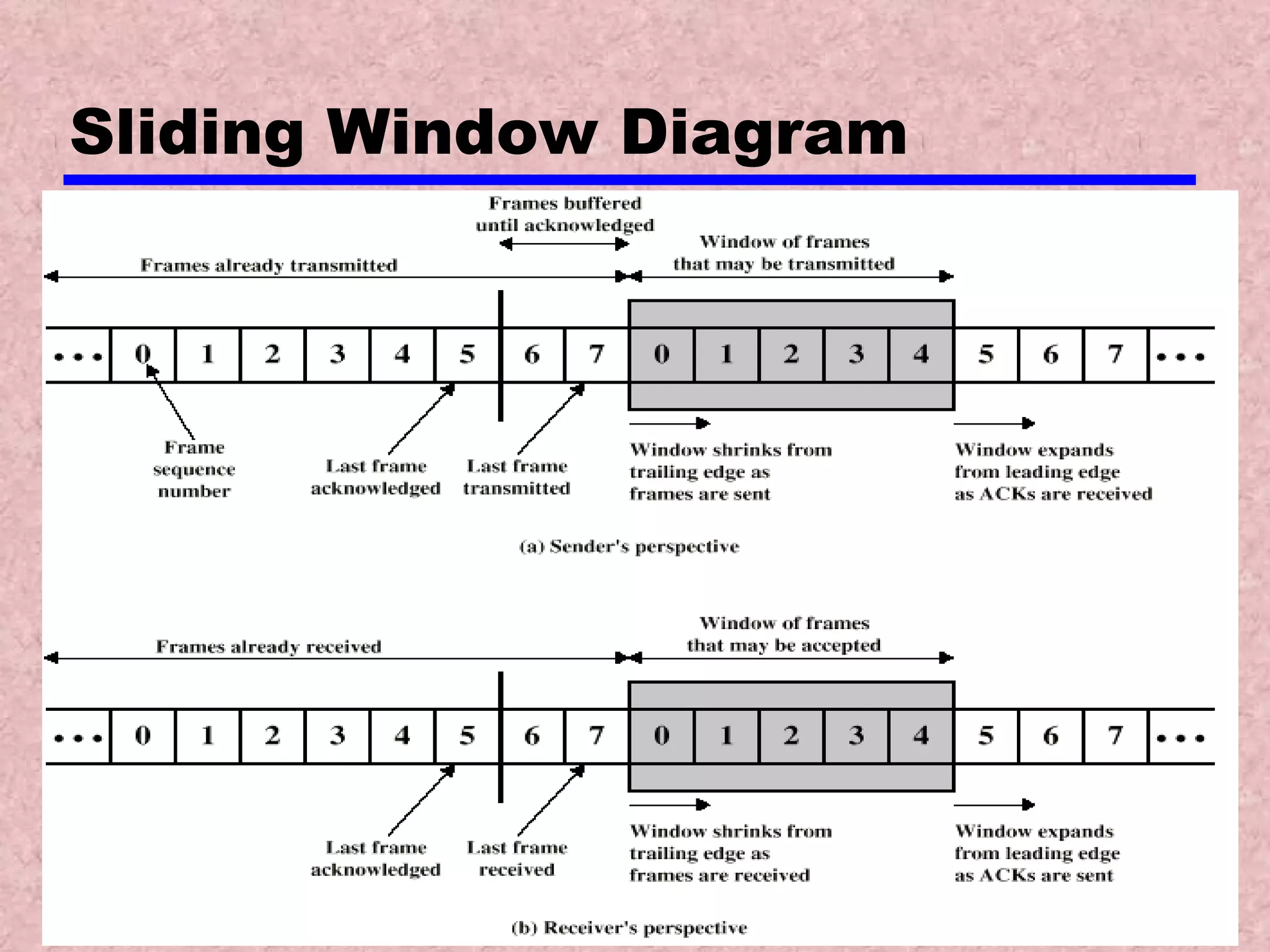
Data Communications - Data Link Control Protocols Key Points
Flow Control Flow control :  Ensuring the sending entity does not overwhelm the receiving entity with data Preventing buffer overflow Transmission time Time taken to emit all bits into medium Propagation time Time for a bit to traverse (merentasi) the link
Model of Frame Transmission (mengelirukan)
Stop and Wait Flow Control The simplest form of flow control Source transmits frame Destination receives frame and replies with acknowledgement (ready to accept another frame) Source waits for ACK before sending next frame Destination can stop flow by not send ACK As long as there are no ACK from dest., source do not sends frame Works well for a message sent in a few large frames
Fragmentation Large block of data may be split into small frames Limited buffer size Errors detected sooner (when whole frame received) On error, retransmission of smaller frames is needed Prevents one station occupying medium for long periods (causing long delays at other sending station) With multiple frames for a single message    inadequate Only one frame at a time can be transit Stop and wait becomes inadequate when the bit length of the link is greater than the frame length (a>1)
Bit length of link B=R x d/V B =  length of the link in bits , this is the number of bits present  on the link at an instance in time when a stream of bits fully occupies the link R = data rate of the link, in bps d = length, or distance of the link in meter V = velocity of propagation, in m/s Propagation delay a = B/L L =  number of bits in the frame (length of the frame in bits)
Stop and Wait Link Utilization length of link > length of frame (1 frame/time =Inefficient) length of link < length of frame
Example
Sliding Windows Flow Control Allow multiple frames to be in transit (improve efficiency ) Receiver has buffer W long Transmitter can send up to W frames without ACK from receiver Each frame is numbered (sequence of order) Receiver sends ACK includes number of next frame expected Transmitter maintains list of sequence no. to send, Receiver maintains list of sequence no. to receive. Sequence number bounded by size of field (k) Frames are numbered modulo 2 k  – numbered 0 to k-1 Eg: if 2 k =8(3 bits), frames are numbered 0,1,2,3,4,5,6,7,0,1,2,3…..7,0..
Sliding Window Diagram- Sender Assume using 2 3 = 8,no. = 0,1,2,3,4,5,6,7,0… Each time  a frame  is sent   window  shrink  (# of frames may be transmitted) Each time  ACK  is received   window  grows  (to end side (total of 7 frames)) acknowledged Sent but not yet acknowledged
Sliding Window Diagram-receiver ACK must includes F0 (RR 0) “ Receiver has received all frames up to F7  and is ready to receive F0.” Each time  a frame  is received    window  shrink  (# of frames available) Each time  ACK  is sent     window  grows  (to end side (total of 7 frames)) *RR = Ready Receive
Example Sliding Window A may transmits 7 frames, beginning with F0 A transmits F0,F1,F2 (no ACK)   A shrunk its window to 4 frames, maintains copy of  F0,F1,F2   A may transmits 4 frames, beginning with F3 B transmits RR 3 frames (received frames up to F2, ready to receive 7 more frames starts from F3) B grows back to 7 frames, starts from F3 A discards copy of  F0,F1,F2 A transmits F3,F4,F5,F6 B returns  RR 4 (ACK F3, allows A  transmits from F4 – F2) By the time RR 4 reaches A, A already transmitted F4,F5,F6,So A can only transmits 4 frames starts from F7. B may receives 7 frames, beginning with F0 B shrunk its window to 4 frames (available frames)
Sliding Window Enhancements Receiver can acknowledge frames without permitting further transmission (Receive Not Ready, RNR) EG: RNR 5 = “I have received all frames up through no. 4 but unable to accept any more at this time” Must send a normal acknowledge to restart transmission If duplex,  2 stations exchange data, both maintain 2 windows (to transmit and to receive) To support this requirement, use piggybacking If no data to send, use acknowledgement frame (RR @ RNR) If data but no acknowledgement to send, send last acknowledgement number again, or have ACK valid flag (TCP)
Error Control Mechanisms of detection and correction of errors  Types of errors Lost frames Damaged frames Automatic repeat request (ARQ) – to turn an unreliable data link to a reliable one ARQ mechanisms: Error detection parity check, CRC, etc. Positive acknowledgment Dest. ACK source received error-free frames. Retransmission after timeout Source retransmits frame not ACK Negative acknowledgement and retransmission Dest. ACK source received error- detected frames. Source retransmits frame
Automatic Repeat Request (ARQ) Three versions of ARQ have been standardized: Stop and wait Go back N Selective reject (selective retransmission)
(a) Stop and Wait Source transmits single frame Wait for ACK If receiver received frame damaged, discard it Transmitter has timeout (transmitter occupied with timer) If no ACK within timeout, retransmit frame If ACK damaged (but arrived), transmitter will not recognize it Transmitter will retransmit Receiver gets two copies of frame Use ACK0 and ACK1
Stop and  Wait - Diagram # of frame :  Labeled alternately 0 and 1 ACK0 :  Receiver received frame 1, Ready to receive frame 0. ACK1 :   Receiver received frame 0, Ready to receive frame 1.
Stop and Wait - Pros and Cons Simple Inefficient
(b) Go Back N (1) Based on sliding window If no error, ACK as usual with next frame expected Use window to control number of outstanding frames If error, reply with rejection (REJ) Discard that frame and all future frames until error frame received correctly Transmitter must go back and retransmit that frame and all subsequent frames
Go Back N - Damaged Frame Receiver detects error in frame  i Receiver sends rejection- i  (REJ  i  ) Transmitter gets rejection- i Transmitter retransmits frame  i  and all subsequent
Go Back N - Lost Frame (1) Case 1: Frame  i   lost Transmitter sends  i+1 Receiver gets frame  i+1  out of sequence Receiver send reject  i  (REJ  i  ) Transmitter goes back to frame  i  and retransmits
Go Back N - Lost Frame (2) Case 2: Frame  i   lost and no additional frame sent Receiver gets nothing and returns neither acknowledgement nor rejection Transmitter times out and sends acknowledgement frame with P bit set to 1.  ( RR(P bit =1) ) Receiver interprets this as command which it acknowledges with the number of the next frame it expects (frame  i  ) .  (RR  i  ) Transmitter then retransmits frame  i
Go Back N –Damaged Acknowledgement (RR @ RNR@ REJ) Receiver gets frame  i  and send acknowledgement ( i+1 ) which is lost  (RR  i+1 ) is sent to transmitter but lost in transmission Acknowledgements are cumulative, so next acknowledgement ( i+n ) may arrive before transmitter times out on frame  i If transmitter times out, it sends acknowledgement with P bit set as before ( RR(P bit =1) ) This can be repeated a number of times before a reset procedure is initiated
Go Back N - Damaged Rejection *Same as for lost frame (2) Receiver gets nothing and returns neither acknowledgement nor rejection Transmitter times out and sends acknowledgement frame with P bit set to 1.  ( RR(P bit =1) ) Receiver interprets this as command which it acknowledges with the number of the next frame it expects (frame  i  ) .  (RR  i  ) Transmitter then retransmits frame  i
Go Back N -  Diagram RR 2: REJ 4: RR(P bit=1)
(c) Selective Reject Also called selective retransmission Only rejected frames are retransmitted Subsequent frames are accepted by the receiver and buffered Minimizes retransmission Receiver must maintain large enough buffer More complex login in transmitter
Selective Reject - Diagram
High Level Data Link Control The important data link control is High Level Data Link Control (HDLC) ISO 33009, ISO 4335 Widely used, basis for some other data link control protocols
HDLC Basic Characteristics Stations type: Primary station Controls operation of link Frames issued are called commands Maintains separate logical link to each secondary station Secondary station Under control of primary station Frames issued called responses Combined station May issue commands and responses
HDLC Link Configurations Link configurations: Unbalanced One primary and one or more secondary stations Supports full duplex and half duplex Balanced Two combined stations Supports full duplex and half duplex
HDLC Transfer Modes (1) Data transfer modes of operation: Normal Response Mode (NRM) Asynchronous Balanced Mode (ABM) Asynchronous Response Mode (ARM)
HDLC Transfer Modes (1) Normal Response Mode (NRM) Unbalanced configuration Primary initiates transfer to secondary Secondary may only transmit data in response to command from primary Used on multi-drop lines Host computer as primary Terminals as secondary
HDLC Transfer Modes (2) Asynchronous Balanced Mode (ABM) Balanced configuration Either station may initiate transmission without receiving permission Most widely used No polling overhead
HDLC Transfer Modes (3) Asynchronous Response Mode (ARM) Unbalanced configuration Secondary may initiate transmission without permission form primary Primary responsible for line rarely used
Frame Structure HDLC uses synchronous transmission (frames) header trailer END!!
Key Points Why do we need data link control protocol? Because of the possibility of transmission errors Because the receiver may need to regulate the rate of the data arrive Because synchronization and interfacing techniques are insufficient by themselves So, we need a layer of control that provide  Flow control, error detection and error control
Key Points -2 Flow control Enables a receiver to regulate the flow of data from a sender so that the receiver’s buffers do not overflow. Error control Achieved by retransmission of damaged frames that have not been acknowledged or for which the other side requests a retransmission High-level data link control (HDLC) Widely used data link control protocol.
Sliding Window Diagram

6 data linkcontrol

  • 1.
    Data Communications -Data Link Control Protocols Key Points
  • 2.
    Flow Control Flowcontrol : Ensuring the sending entity does not overwhelm the receiving entity with data Preventing buffer overflow Transmission time Time taken to emit all bits into medium Propagation time Time for a bit to traverse (merentasi) the link
  • 3.
    Model of FrameTransmission (mengelirukan)
  • 4.
    Stop and WaitFlow Control The simplest form of flow control Source transmits frame Destination receives frame and replies with acknowledgement (ready to accept another frame) Source waits for ACK before sending next frame Destination can stop flow by not send ACK As long as there are no ACK from dest., source do not sends frame Works well for a message sent in a few large frames
  • 5.
    Fragmentation Large blockof data may be split into small frames Limited buffer size Errors detected sooner (when whole frame received) On error, retransmission of smaller frames is needed Prevents one station occupying medium for long periods (causing long delays at other sending station) With multiple frames for a single message  inadequate Only one frame at a time can be transit Stop and wait becomes inadequate when the bit length of the link is greater than the frame length (a>1)
  • 6.
    Bit length oflink B=R x d/V B = length of the link in bits , this is the number of bits present on the link at an instance in time when a stream of bits fully occupies the link R = data rate of the link, in bps d = length, or distance of the link in meter V = velocity of propagation, in m/s Propagation delay a = B/L L = number of bits in the frame (length of the frame in bits)
  • 7.
    Stop and WaitLink Utilization length of link > length of frame (1 frame/time =Inefficient) length of link < length of frame
  • 8.
  • 9.
    Sliding Windows FlowControl Allow multiple frames to be in transit (improve efficiency ) Receiver has buffer W long Transmitter can send up to W frames without ACK from receiver Each frame is numbered (sequence of order) Receiver sends ACK includes number of next frame expected Transmitter maintains list of sequence no. to send, Receiver maintains list of sequence no. to receive. Sequence number bounded by size of field (k) Frames are numbered modulo 2 k – numbered 0 to k-1 Eg: if 2 k =8(3 bits), frames are numbered 0,1,2,3,4,5,6,7,0,1,2,3…..7,0..
  • 10.
    Sliding Window Diagram-Sender Assume using 2 3 = 8,no. = 0,1,2,3,4,5,6,7,0… Each time a frame is sent  window shrink (# of frames may be transmitted) Each time ACK is received  window grows (to end side (total of 7 frames)) acknowledged Sent but not yet acknowledged
  • 11.
    Sliding Window Diagram-receiverACK must includes F0 (RR 0) “ Receiver has received all frames up to F7 and is ready to receive F0.” Each time a frame is received  window shrink (# of frames available) Each time ACK is sent  window grows (to end side (total of 7 frames)) *RR = Ready Receive
  • 12.
    Example Sliding WindowA may transmits 7 frames, beginning with F0 A transmits F0,F1,F2 (no ACK) A shrunk its window to 4 frames, maintains copy of F0,F1,F2 A may transmits 4 frames, beginning with F3 B transmits RR 3 frames (received frames up to F2, ready to receive 7 more frames starts from F3) B grows back to 7 frames, starts from F3 A discards copy of F0,F1,F2 A transmits F3,F4,F5,F6 B returns RR 4 (ACK F3, allows A transmits from F4 – F2) By the time RR 4 reaches A, A already transmitted F4,F5,F6,So A can only transmits 4 frames starts from F7. B may receives 7 frames, beginning with F0 B shrunk its window to 4 frames (available frames)
  • 13.
    Sliding Window EnhancementsReceiver can acknowledge frames without permitting further transmission (Receive Not Ready, RNR) EG: RNR 5 = “I have received all frames up through no. 4 but unable to accept any more at this time” Must send a normal acknowledge to restart transmission If duplex, 2 stations exchange data, both maintain 2 windows (to transmit and to receive) To support this requirement, use piggybacking If no data to send, use acknowledgement frame (RR @ RNR) If data but no acknowledgement to send, send last acknowledgement number again, or have ACK valid flag (TCP)
  • 14.
    Error Control Mechanismsof detection and correction of errors Types of errors Lost frames Damaged frames Automatic repeat request (ARQ) – to turn an unreliable data link to a reliable one ARQ mechanisms: Error detection parity check, CRC, etc. Positive acknowledgment Dest. ACK source received error-free frames. Retransmission after timeout Source retransmits frame not ACK Negative acknowledgement and retransmission Dest. ACK source received error- detected frames. Source retransmits frame
  • 15.
    Automatic Repeat Request(ARQ) Three versions of ARQ have been standardized: Stop and wait Go back N Selective reject (selective retransmission)
  • 16.
    (a) Stop andWait Source transmits single frame Wait for ACK If receiver received frame damaged, discard it Transmitter has timeout (transmitter occupied with timer) If no ACK within timeout, retransmit frame If ACK damaged (but arrived), transmitter will not recognize it Transmitter will retransmit Receiver gets two copies of frame Use ACK0 and ACK1
  • 17.
    Stop and Wait - Diagram # of frame : Labeled alternately 0 and 1 ACK0 : Receiver received frame 1, Ready to receive frame 0. ACK1 : Receiver received frame 0, Ready to receive frame 1.
  • 18.
    Stop and Wait- Pros and Cons Simple Inefficient
  • 19.
    (b) Go BackN (1) Based on sliding window If no error, ACK as usual with next frame expected Use window to control number of outstanding frames If error, reply with rejection (REJ) Discard that frame and all future frames until error frame received correctly Transmitter must go back and retransmit that frame and all subsequent frames
  • 20.
    Go Back N- Damaged Frame Receiver detects error in frame i Receiver sends rejection- i (REJ i ) Transmitter gets rejection- i Transmitter retransmits frame i and all subsequent
  • 21.
    Go Back N- Lost Frame (1) Case 1: Frame i lost Transmitter sends i+1 Receiver gets frame i+1 out of sequence Receiver send reject i (REJ i ) Transmitter goes back to frame i and retransmits
  • 22.
    Go Back N- Lost Frame (2) Case 2: Frame i lost and no additional frame sent Receiver gets nothing and returns neither acknowledgement nor rejection Transmitter times out and sends acknowledgement frame with P bit set to 1. ( RR(P bit =1) ) Receiver interprets this as command which it acknowledges with the number of the next frame it expects (frame i ) . (RR i ) Transmitter then retransmits frame i
  • 23.
    Go Back N–Damaged Acknowledgement (RR @ RNR@ REJ) Receiver gets frame i and send acknowledgement ( i+1 ) which is lost (RR i+1 ) is sent to transmitter but lost in transmission Acknowledgements are cumulative, so next acknowledgement ( i+n ) may arrive before transmitter times out on frame i If transmitter times out, it sends acknowledgement with P bit set as before ( RR(P bit =1) ) This can be repeated a number of times before a reset procedure is initiated
  • 24.
    Go Back N- Damaged Rejection *Same as for lost frame (2) Receiver gets nothing and returns neither acknowledgement nor rejection Transmitter times out and sends acknowledgement frame with P bit set to 1. ( RR(P bit =1) ) Receiver interprets this as command which it acknowledges with the number of the next frame it expects (frame i ) . (RR i ) Transmitter then retransmits frame i
  • 25.
    Go Back N- Diagram RR 2: REJ 4: RR(P bit=1)
  • 26.
    (c) Selective RejectAlso called selective retransmission Only rejected frames are retransmitted Subsequent frames are accepted by the receiver and buffered Minimizes retransmission Receiver must maintain large enough buffer More complex login in transmitter
  • 27.
  • 28.
    High Level DataLink Control The important data link control is High Level Data Link Control (HDLC) ISO 33009, ISO 4335 Widely used, basis for some other data link control protocols
  • 29.
    HDLC Basic CharacteristicsStations type: Primary station Controls operation of link Frames issued are called commands Maintains separate logical link to each secondary station Secondary station Under control of primary station Frames issued called responses Combined station May issue commands and responses
  • 30.
    HDLC Link ConfigurationsLink configurations: Unbalanced One primary and one or more secondary stations Supports full duplex and half duplex Balanced Two combined stations Supports full duplex and half duplex
  • 31.
    HDLC Transfer Modes(1) Data transfer modes of operation: Normal Response Mode (NRM) Asynchronous Balanced Mode (ABM) Asynchronous Response Mode (ARM)
  • 32.
    HDLC Transfer Modes(1) Normal Response Mode (NRM) Unbalanced configuration Primary initiates transfer to secondary Secondary may only transmit data in response to command from primary Used on multi-drop lines Host computer as primary Terminals as secondary
  • 33.
    HDLC Transfer Modes(2) Asynchronous Balanced Mode (ABM) Balanced configuration Either station may initiate transmission without receiving permission Most widely used No polling overhead
  • 34.
    HDLC Transfer Modes(3) Asynchronous Response Mode (ARM) Unbalanced configuration Secondary may initiate transmission without permission form primary Primary responsible for line rarely used
  • 35.
    Frame Structure HDLCuses synchronous transmission (frames) header trailer END!!
  • 36.
    Key Points Whydo we need data link control protocol? Because of the possibility of transmission errors Because the receiver may need to regulate the rate of the data arrive Because synchronization and interfacing techniques are insufficient by themselves So, we need a layer of control that provide Flow control, error detection and error control
  • 37.
    Key Points -2Flow control Enables a receiver to regulate the flow of data from a sender so that the receiver’s buffers do not overflow. Error control Achieved by retransmission of damaged frames that have not been acknowledged or for which the other side requests a retransmission High-level data link control (HDLC) Widely used data link control protocol.
  • 38.