Arduino Display Guide: How to Add an OLED Display to Arduino
Adding an OLED display is one of the easiest ways to improve an Arduino project. You can show sensor values, system status, menus, or simple graphics in real time.
An OLED display works especially well as an Arduino display. It has high contrast, low power consumption, and simple wiring. Most OLED modules use I2C, so only a few pins are needed.
In this tutorial, you’ll learn how to add an OLED display to Arduino step by step. We’ll cover hardware connections, library installation, and example code. No complex setup. No unnecessary theory.
Once the display is working, you can reuse it in many projects—dashboards, IoT devices, clocks, or control panels.
Let’s start with the hardware setup.
Hardware Preparation
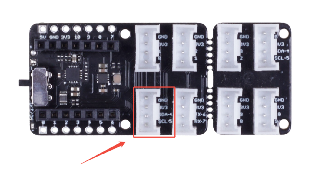
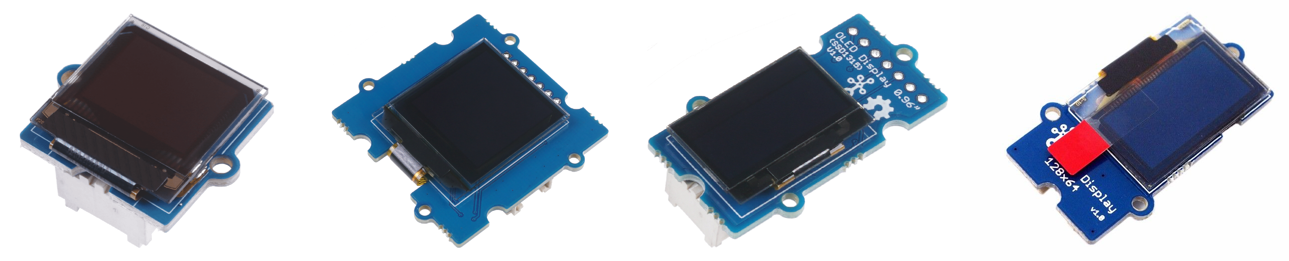
For this tutorial, we use a little 1.12-inch Grove-OLED display and a Grove extension board. The Grove series has a standardised 4-pin connector, a foolproof design, and quick assembly.
So what you need to do is connect the module to the I2C port on the extension board. The 4 pins are defined as below.
| pin | Function | Note | Cable color |
|---|---|---|---|
| pin1 | SCL | I2C Clock | YELLOW |
| pin2 | SDA | I2C Data | WHITE |
| pin3 | VCC | Power, 5V/3.3V | RED |
| pin4 | GND | Ground | BLACK |
Hardware that you need:

Connect the Grove-OLED Display 1.12” to the I2C port of the extension board via the Grove cable.
Software Preparation
Step 1. Download and install the latest version of Arduino IDE according to your operating system

Step 2. Launch the Arduino application
Step 3. Add the ESP32 board package to your Arduino IDE
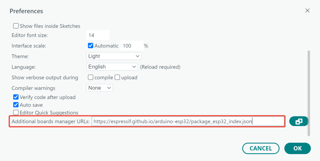
Navigate to File > Preferences, and fill “Additional Boards Manager URLs” with the URL below:
https://espressif.github.io/arduino-esp32/package_esp32_index.json
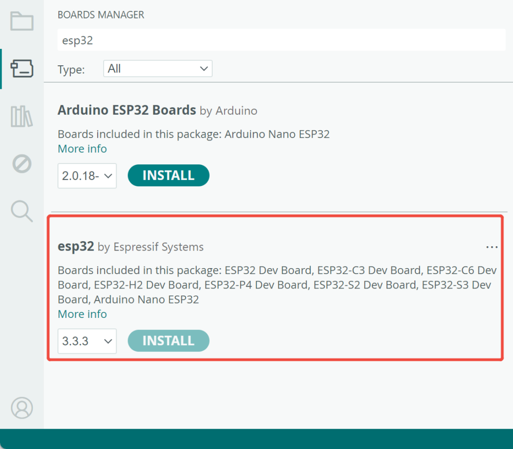
Navigate to Tools > Board > Boards Manager, type the keyword “esp32” in the search box, select the latest version of esp32, and install it.
Step 4. Select your board and port
Board
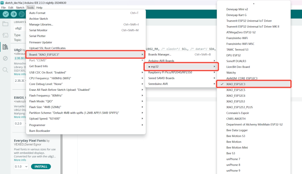
Navigate to Tools > Board > ESP32 Arduino and select “XIAO_ESP32C3”.
Port
Navigate to Tools > Port and select the serial port name of the connected XIAO ESP32C3. This is likely to be COM3 or higher (COM1 and COM2 are usually reserved for hardware serial ports).
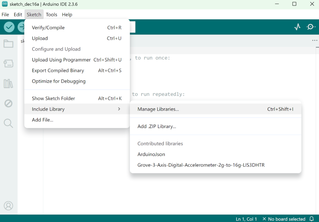
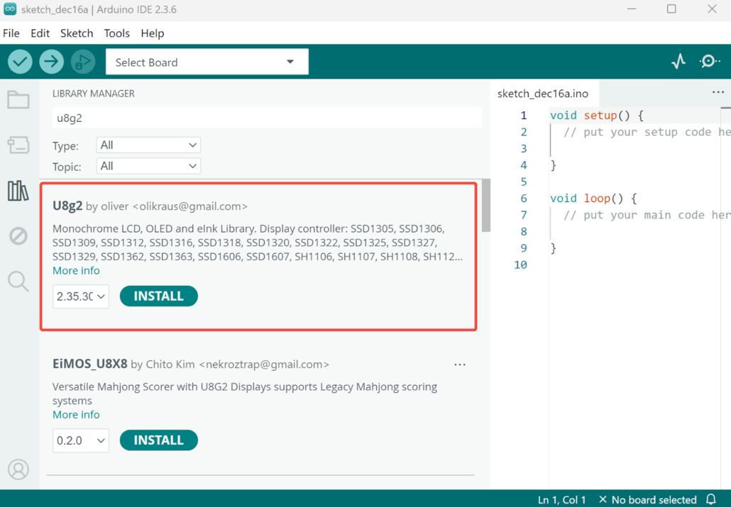
Step 5. Open Arduino IDE and the Library Manager (Sketch > Include Library > manage Libraries) to install the library of u8g2.
Step 6. Enter “u8g2” into the search field, select the latest version and click the “Install” button.
Step 7. Upload the demo code below to your Arduino IDE.
#include <Arduino.h>
#include <U8g2lib.h>
#include <SPI.h>
#include <Wire.h>

U8G2_SH1107_SEEED_128X128_1_SW_I2C u8g2(U8G2_R0, /* clock=*/ SCL, /* data=*/ SDA, /* reset=*/ U8X8_PIN_NONE);

void setup(void) {
  u8g2.begin();
}

void loop(void) {
  u8g2.firstPage();
  do {
    u8g2.setFont(u8g2_font_ncenB10_tr);
    u8g2.drawStr(0,24,"Hello World!");
  } while ( u8g2.nextPage() );
}
There will be a “Hello World!” displayed on the screen of the Grove – OLED Display 1.12” if everything goes well.

Alternative Options
For the hardware, you can also use XIAO ESP32-S3 and XIAO ESP32-C6 to replace the C3.
For the OLED display, Seeed also offers more options that can be used in this tutorial:
Note: The code needs to be revised for a different display. Please check the following wiki for details:
https://wiki.seeedstudio.com/Grove-OLED_Display_0.96inch/
https://wiki.seeedstudio.com/Grove-OLED-Display-0.66-SSD1306_v1.0/
https://wiki.seeedstudio.com/Grove-OLED-Yellow&Blue-Display-0.96-SSD1315_V1.0/
https://wiki.seeedstudio.com/Grove-OLED-Display-1.12-SH1107_V3.0/
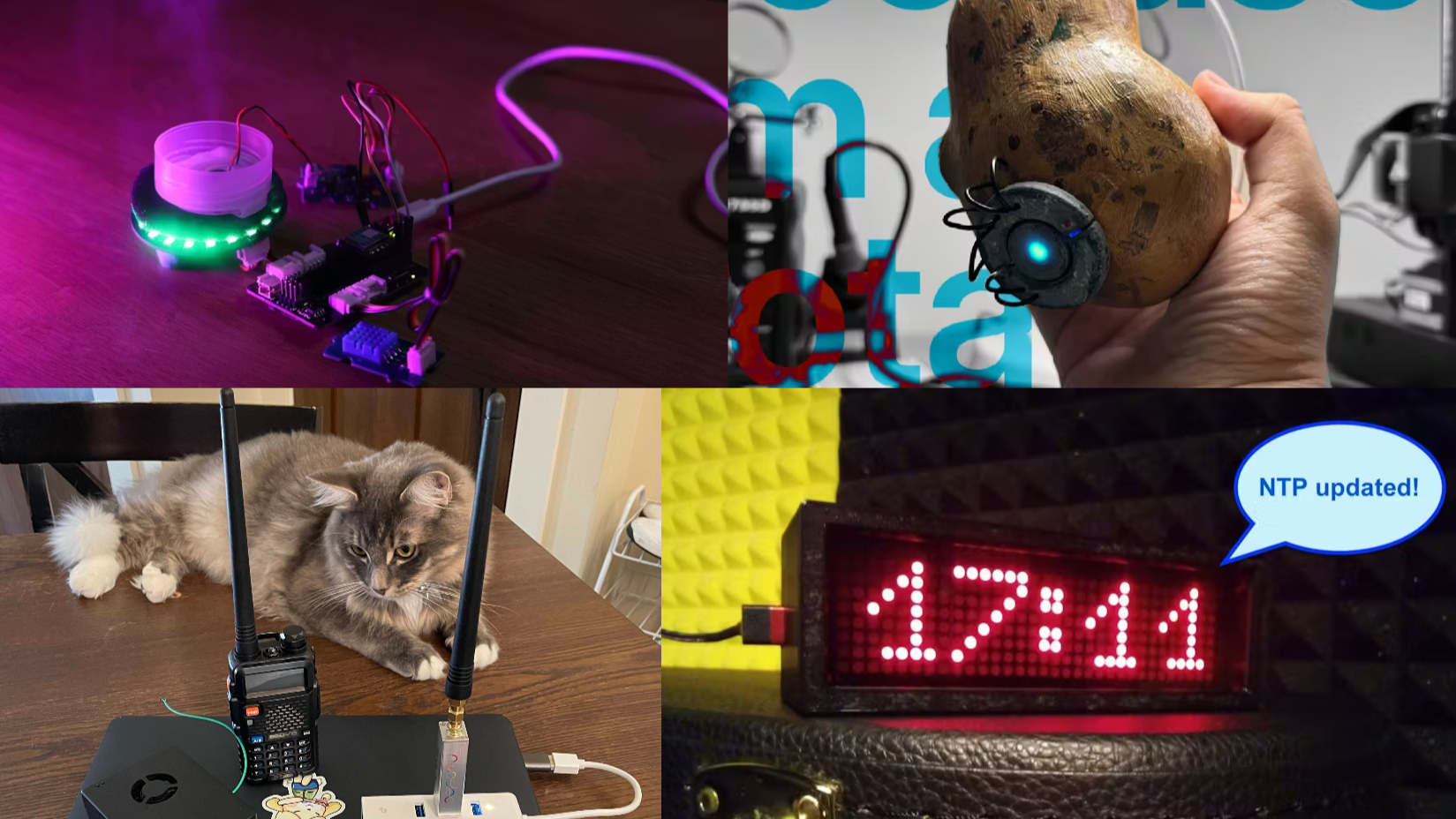
Awesome Arduino OLED Projects
Dasai Mochi-Style OLED Display Project
This project recreates the popular Dasai Mochi car companion as a small OLED display project. Maker upir uses an SSD1306 128×32 I2C OLED, ESP32 (XIAO ESP32-S3), and an expansion board to show static images and simple animations. It’s a great example of using a small Arduino-compatible OLED display for UI graphics and animation rather than text-only output.
Source files: https://github.com/upiir/esp32s3_oled_dasai_mochi
Gus 2.0: Emotion-Based Room Health Monitor with OLED Display
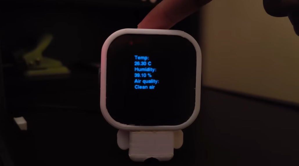
Maker Makestreme made Gus 2.0, a compact robot that visualizes room health through emotions. Gus’s eye levels actually tell you how comfy your room is. So, if the air quality’s not great, or the humidity’s off, or the temperature’s just not right, his eyelids start to droop, and he gets a little gloomy.
The project uses the same 1.12-inch OLED display in this tutorial, together with a Grove air quality sensor, demonstrating how an Arduino OLED display can turn sensor data into intuitive visual feedback.
Source files: https://www.hackster.io/makestreme/gus-2-0-uses-emotions-to-indicate-room-health-7b6def
Conclusion
An OLED display is a simple and reliable option for building an Arduino display. With basic I2C wiring, a stable library, and a short test sketch, you can get useful on-screen output up and running quickly. This tutorial keeps the setup straightforward and beginner-friendly, making it a good starting point for your first Arduino display project. From here, you can expand the same setup into dashboards, indicators, or custom interfaces as your projects grow.
>> Read more
Add your description here…
Add your description here…