580 California St., Suite 400
San Francisco, CA, 94104
This research theme focuses on the design principles and component selection that maximize the selectivity, sensitivity, stability, and reproducibility of biosensors for detecting specific analytes. It addresses biosensor architecture including bioreceptor choice (enzymes, antibodies, aptamers, cells), transducer type (electrochemical, optical, piezoelectric), and signal processing to meet requirements in clinical diagnostics, environmental monitoring, and food safety. Understanding these design aspects is crucial for developing applications with reliable real-time detection and low detection limits.
This research area investigates innovations in sensor materials, such as ionophore-based membranes, nanomaterials, and semiconductor compounds, alongside enhanced transduction mechanisms (electrochemical, optical, conductometric) that confer improved selectivity, sensitivity, and miniaturization. Understanding material-transducer interactions and response dynamics enables the development of sensors capable of real-time, on-site, and multiplexed chemical detection in complex matrices.
Research in this area explores the translation of biosensor principles into portable, user-friendly devices enabling rapid, on-site detection of contaminants in environmental and food matrices. The focus is on miniaturization, multiplexing, enhancing real-time data acquisition, and portability while maintaining analytical rigor. This work is critical for addressing challenges of timely pollutant detection under resource-limited conditions, facilitating preventative monitoring and safety enforcement in public health and environmental contexts.
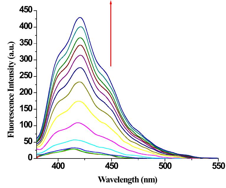
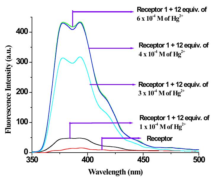
![Figure 9S. (a) Change in emission of 2 (c = 2.5 x 10° M) in THF-Water (3:1 v/v) upon addition of 10 equiv. of Hg(ClO,)> (c = 1 x 10° M ); (b) fluorescence Job plot for 2 with Hg” ({H] = [G] = 2.5 x 10° M).](https://figures.academia-assets.com/112208460/figure_009.jpg)
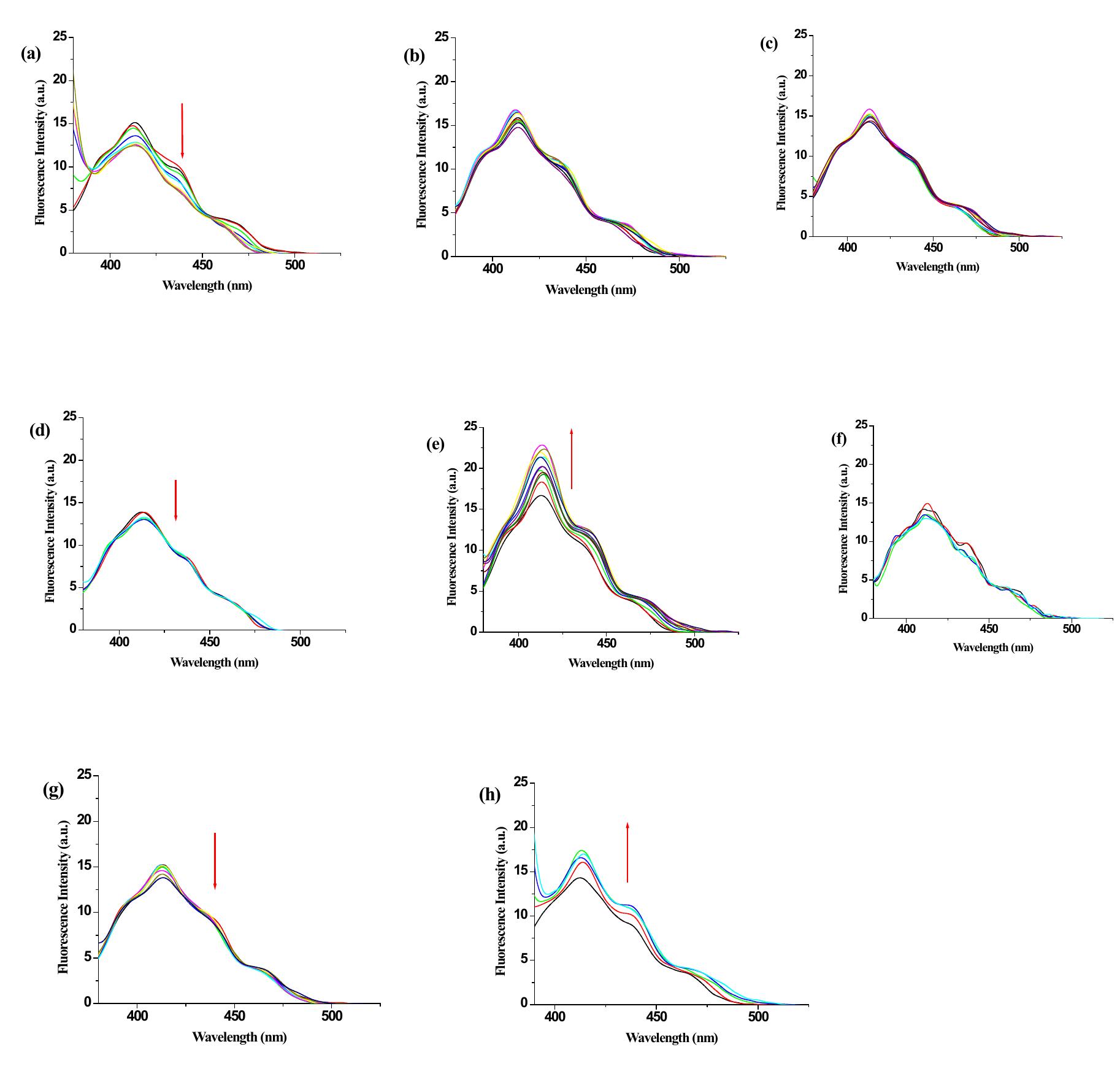
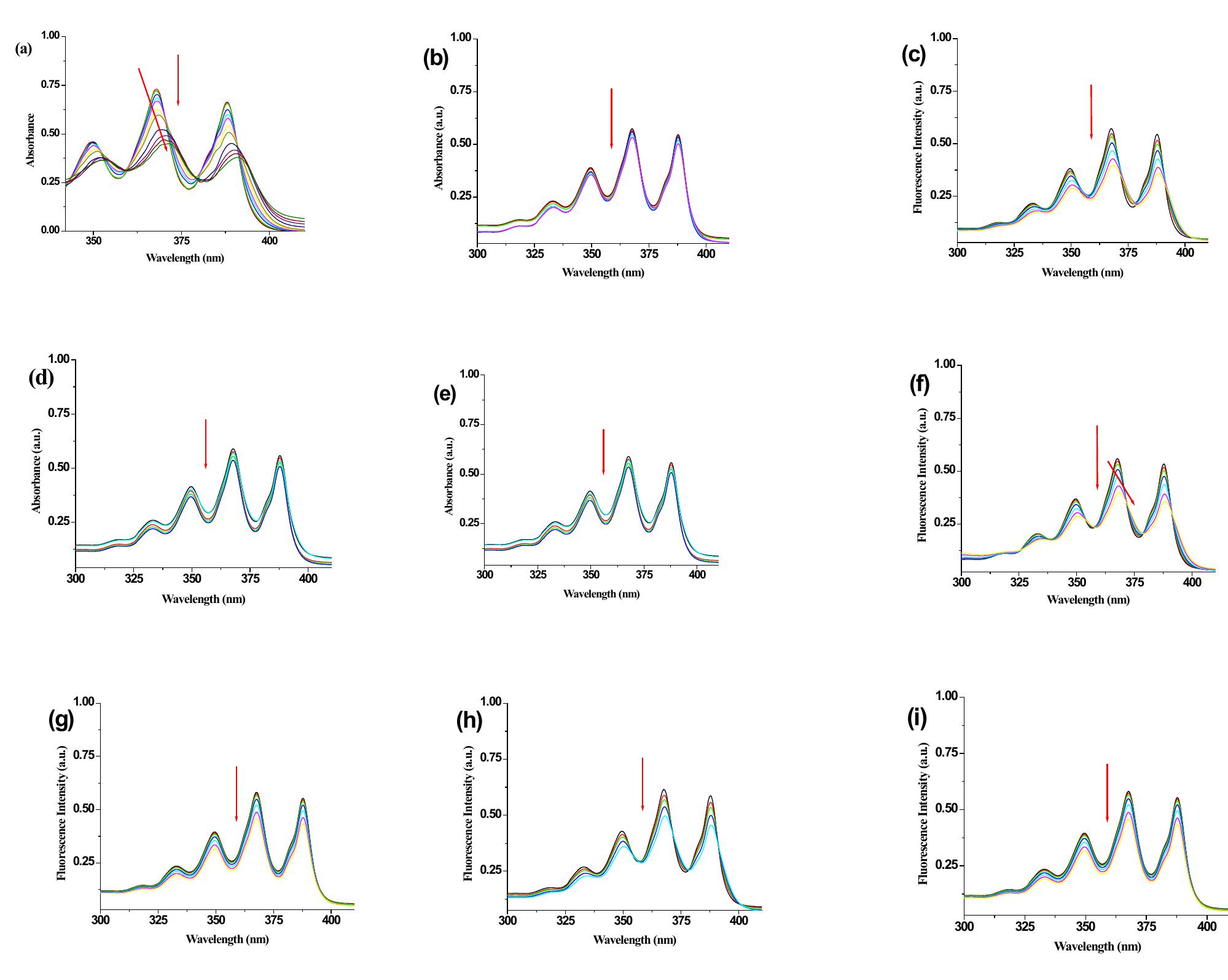
![Figure 1S. Change in emission of 1 (¢c = 2.5 x 10° M) in THF upon addition of (a) AgClO, , (b) Zn(ClO4)2, (c) Cd(C104)2, (d) Co(ClO4)2 (e) Cu(ClO4)2, (f) Mg(ClO4)2, (g) Ni(ClO4)2, (h) Pb(C104)>, [concentration of metal salts were 1 x 10° M]. 1. Change in emission of receptor 1 with various metal ions in THF](https://figures.academia-assets.com/112208460/figure_001.jpg)
![Figure 4S. UV-vis Job plot for receptor 1 with Hg’** ({H] = [G] =2.5 x 10° M). 4. UV-Vis Job plot of receptor 1 with Hg(ClO4)2 in (THF-H,0, 3:1 v/v ).](https://figures.academia-assets.com/112208460/figure_004.jpg)

![Fig. 4. Ternary inverter with three logical states. (a) Schematic illustration of the ternary inverter. (b) Equivalent circuit configuration of the ternary inverter. (c) Optical image of the ternary inverter. (d) Vin versus Vour characteristic of the ternary inverter. The inset shows an input-output table of the ternary inverter. (e, f) Load-line analysis of the ternary inverter circuit under three bias conditions: (e) 5 V < Vin <8 V, 20 V < Vin < 25 V and (f) 12 V < Vin < 18 V. The I-V characteristics of the phosphorene (BP)/ReS; NDR device (driver) and the BP TFT (load resistor) are represented by solid and dashed lines, respectively. Reprinted from Ref. [108] with permission.](https://figures.academia-assets.com/110312048/figure_004.jpg)
![Fig. 7. The photo-induced logic OR gate based on Cu/CH3NH3PbI3/PEDOT:PSS/ITO memristor (a). The current-time response of the device at the initial high resistive stat (HRS) upon pulsed illumination at read potential of 10 mV (b), the current-time response of the device at the initial low resistive state (LRS) upon pulsed illumination at rea potential of 10 mV (c), the two (optical and electrical) input OR truth table (d). Adapted from Ref. [165] with permission from The Royal Society of Chemistry. The clearest and most convincing demonstration of a light- controlled memristor would be a device which exhibits a memris- tive hysteresis loop (the fingerprint of a memristor) only upon irra- diation. Such a device, made of superhydrophobic ZnO nanorods covered with a thin layer of water, acts as a memristor or a resistor under illumination or in the dark respectively [166]. The water layer allows to choose resistive or memristive properties upon con- stant irradiation by simple manipulation of a light incident angle due to different refractive indexes of air and water. After exceeding the angle of incidence critical value of 0 = 48°, the device loses its memnristive properties because the light does not reach the ZnO layer anymore. In the device there is also an air pocket located beneath the water layer. It acts as an oxygen source for the ZnO nanorods surface. The illumination induces desorption of the che- misorbed oxygen. That allows oxygen vacancies movement and the formation of conductive filaments between top and bottom elec- trodes. Without the irradiation the adsorbed oxygen prevents dif- fusion of oxygen vacancies and the device remains in the high resistive state. An interesting concept of reconfigurable OR and AND logic gates have been realised with ITO/CeO2_,/AlO,/Al memristor [161]. For](https://figures.academia-assets.com/110312048/figure_007.jpg)
![Fig. 10. The current-voltage characteristics of Au/MoS, nanospheres/Au memristor in the dark or under illumination recorded with the scan rate of 50 mV/s in (a) +3 V an (b) +6 V sweeping voltage range. The arrows indicate the direction of current changes. Reprinted from [170] with permission of Springer-Nature. The pinched hysteresis loop is called the fingerprint of a mem- ristor [179]. The photo-memristive behaviour can be achieved not only under static optical conditions like the constant illumination or in the dark but also by changing the light intensity in appropriate moments. An excellent example is given by a photo- controllable graphene/diamond heterojunction [164]. For the mea- surement taken at 150 °C the ohmic behaviour has been observed in the dark but under illumination with the blue light the rectifying behaviour appears. Separately, those characteristics are not mem- ristive (Fig. 11a). The pulsed irradiation with the blue light (5 s) during the potential sweep at 10 V changes the state of the device from the initial HRS to the low resistive state (LRS). An another pulsed irradiation at —10 V (5s) changes the state of the device from LRS to HRS. This two steps resulting in the memristive Although the control over conductance by an additional light stimulation is an obvious advantage, the light can also probe the current state of the device (e.g., distinguish between HRS and LRS). A planar graphene/SiO, device has a strong electrolumines- cence related to its resistance states [171]. For the HRS and LRS the maxima of the electroluminescence are around 550 nm and 770 nm respectively. A strong emission of light was observed espe- cially during switching device from the LRS to the HRS. This kind of surplus optical output can be useful to create optical communica- tion path with other photonic devices. A light emitting cel](https://figures.academia-assets.com/110312048/figure_010.jpg)
![Fig. 2. The colour-coded design concept (top) and a corresponding molecular structure (bottom) of the tree-input logic gate. Adapted from Ref. [96].](https://figures.academia-assets.com/110312048/figure_002.jpg)
![Fig. 5. A projection of the selected photocurrent action spectrum with ternary logic values assigned and the interpretation of the obtained result in terms of three- valued logic circuit operation. Adapted from Ref. [8].](https://figures.academia-assets.com/110312048/figure_005.jpg)
![Fig. 6. The effect of fuzzification for both inputs (a and b) and output (c) presented with the rules base for the inference engine (d). The result of the defuzzification step (e with the photocurrent map used for the construction of the fuzzy logic system (f). Adapted from Ref. [8].](https://figures.academia-assets.com/110312048/figure_006.jpg)
![Fig. 3. The structure of Ruz complex (a), the pH dependence of the photocurrent polarity within 0-10 range recorded for GO/Ruz thin film electrodes biased at 0.1 V vs. SCE (b), the mechanism of cathodic photocurrent generation at pH = 1 (c) and the mechanism of anodic photocurrent generation at pH = 10 (d). Adapted from Ref. [97].](https://figures.academia-assets.com/110312048/figure_003.jpg)
![Fig. 1. A schematic illustration of various strategies for creating PEC sensors: surface plasmon resonance (a), resonant energy transfer (b), chemiluminescence- based energy transfer (c), charge separation (d), electron trapping (e), competitive electron transfer (f, g), conditional, analyte-induced photosensitization (h), intro- duction/release of photoactive species (i), consumption/generation of electron donor/acceptor (j) and effect of steric hindrance (k). Adapted from Ref. [46].](https://figures.academia-assets.com/110312048/figure_001.jpg)
![Fig. 9. The schematic representation of memristive device (a), the bidirectional hysteresis loop (b), the conduction and valence band profiles, interband absorption and electron/holes dynamics at —1.8 V (c) and 0 V (d). Intraband absorption at —1.8 V (e). Reprinted from Ref. [177] with permission of AIP Publishing.](https://figures.academia-assets.com/110312048/figure_009.jpg)
![Fig. 11. The current-voltage characteristics of the graphene/diamond memristive device at 200 °C with (red) and without white light illumination (a), the current-voltage characteristics of the memristive junction at 150 °C (b). The resistive states were changed to HRS or LRS by the illumination at +10 V and —10 V for 5 s. Reproduced from Ref. [164] with permission of AIP Publishing.](https://figures.academia-assets.com/110312048/figure_011.jpg)
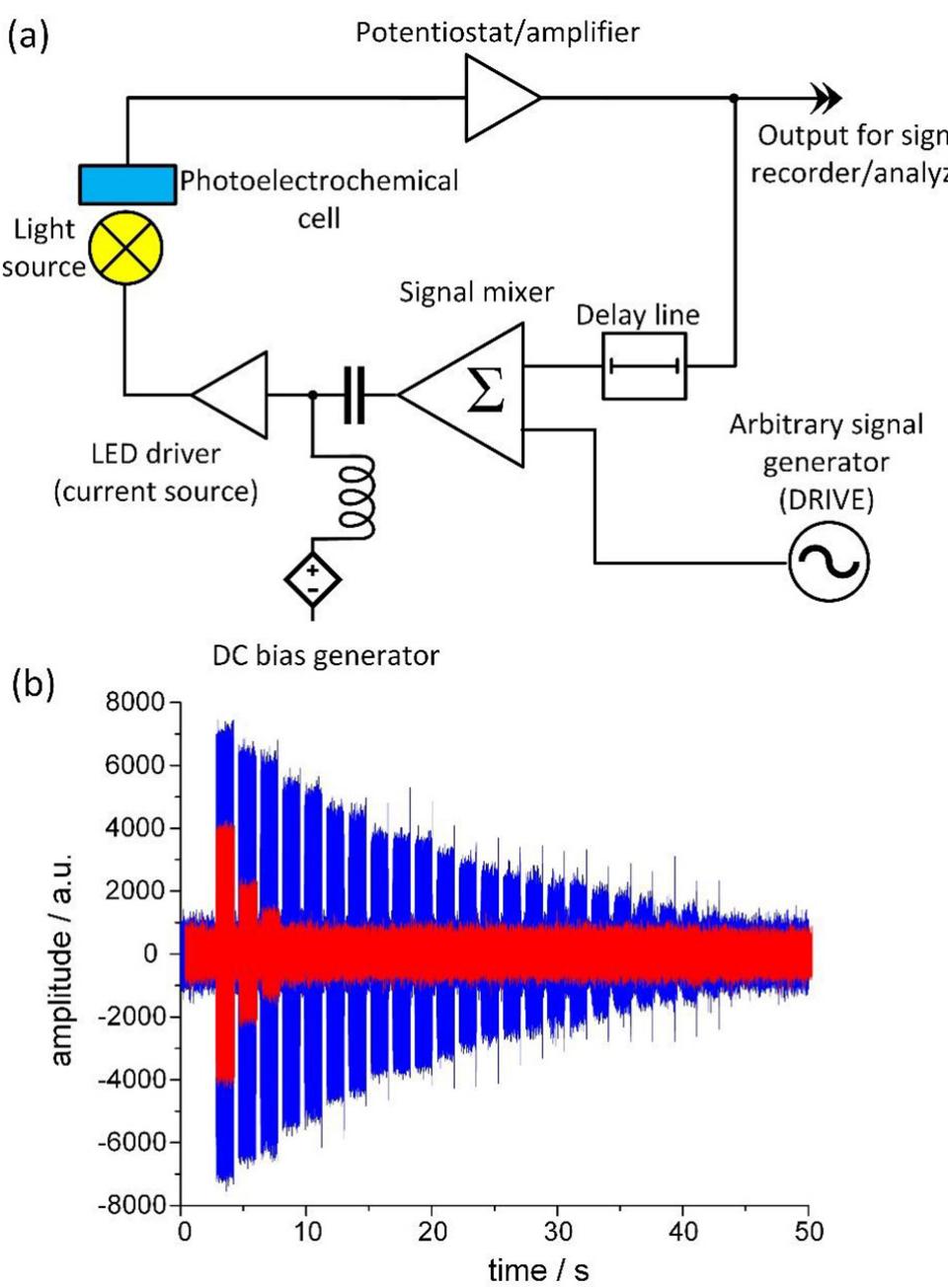
![Fig. 15. The overview of the SWEET sensing setup. The environment-sensitive reservoir is used to obtain information about the environment. This is done through indirect sensing by studying the response of the reservoir to user-provided queries - the drive signal u(t). The delayed feedback At (a) is added to increase the complexity of the configuration space and achieve better reservoir computing properties. (b) On the left, the case of a low phase space separation is illustrated. The trajectories mix under different environmental conditions. To build a sensor with such a system a complex readout layer is required, which implies overhead costs in the terms of engineering effort, computational complexity or energy. On the right the case of a high phase space separation is shown. Different colours correspond to the regions that the system visits under different environmental conditions. In this scenario, a relatively simple readout layer can be used to infer the state of the environment. Most of the computation is performed by the device, and not the readout layer. Adapted from Ref. [40].](https://figures.academia-assets.com/110312048/figure_015.jpg)
![Fig. 8. The implementation of ITO/CeO2_,/AlOy/Al memristor as reconfigurable AND and OR logic gates. (a) Schematic diagram of OR and AND logic operations, in the greet frame the optical-set and electrical-reset operations are shown, (b) an electrical outputs (red and blue) with the corresponding electrical and optical inputs (black), (c) the truth table with output current values for the AND and OR logic operations. The read voltage was 0.2 V. Reprinted from Ref. [161] with permission. Examples of devices with the memristive behaviour in the dark and an additional modulation option upon illumination (ON or OFF) can be found. A memristive device composed of GaAs/AlGaAs An interesting alteration of memristive properties and the cur- rent-voltage characteristic can be observed in graphene/graphene oxide and MoS; based devices [163,170]. Although different mech- anisms are responsible for the memristive properties of these two systems, in both cases the set and reset operations in the dark and upon illumination occur at the potential values of opposite polarity i.e., set/reset voltage is about 3.3/—3.8 V in the dark and —3.5/4V](https://figures.academia-assets.com/110312048/figure_008.jpg)
![Fig. 13. A schematic structure of delay-based reservoir computer with feedbacl loop. Input data undergoes sampling and hold functions for the duration of the delay line (represented by t). The procedure of masking and time-multiplexins enables division of duration of delay line to create temporally separated virtua nodes (distances between virtual nodes are marked by 0, (a). A schematic representation of input data pre-processing and masking procedures. Time. continuous or time-discreet signal is sampled and held for the duration of the delay line. By time-multiplexing, duration of delay line is divided, so that maskins function can attribute different states for each virtual neuron (b). Adapted from Ref [191].](https://figures.academia-assets.com/110312048/figure_012.jpg)
![Figure 17. Transmission electron micrograph of protein-stained microtome section from a sonochemically prepared protein microspheres [55].](https://figures.academia-assets.com/109121385/figure_011.jpg)
![Figure 9. Transmission electron micrograph of sonochemically-prepared iron colloid stabilized by oleic acid [31]. Sonochemical decomposition of iron pentacarbonyl in the presence of stabilizers such as polyvinylpyrrolidone or oleic acid produced a colloid of nanometer sized iron particles [31]. Transmission electron micrographs show that the iron particles have a relatively narrow range in size from 3 to 8 nm for polyvinylpyrrolidone, while oleic acid gives an even more uniform distribution at 8 nm (Figure 9). Electron microdiffraction revealed that the particles are amorphous on the nanometer scale as formed and that after in situ electron beam heating these particles crystallize to bec iron.](https://figures.academia-assets.com/109121385/figure_007.jpg)
![Figure 3. A typical sonochemical apparatus with direct immersion ultrasonic horn. Ultrasound can be easily introduced into a chemical reaction with good control of temperature and ambient atmosphere. The usual piezoelectric ceramic is PZT, a lead zirconate titanate ceramic. Similar designs for sealed stainless steel cells can operate at pressures above 10 bar. the liquid-solid interface. For such reactions, a common ultrasonic cleaning bath will therefore often suffice. The low intensity available in these devices [= 1 Wiem’], however, can prove limiting. In addition, the standing wave patterns in ultrasonic cleaners require accurate positioning of the reaction vessel. On the other hand, ultrasonic cleaning baths are easily accessible, relatively inexpensive, and useable on moderately large scale. Finally, for larger scale irradiations, flow reactors with high ultrasonic intensities are commercially available in modular units of as much as 20 kW [34, 35].](https://figures.academia-assets.com/109121385/figure_003.jpg)
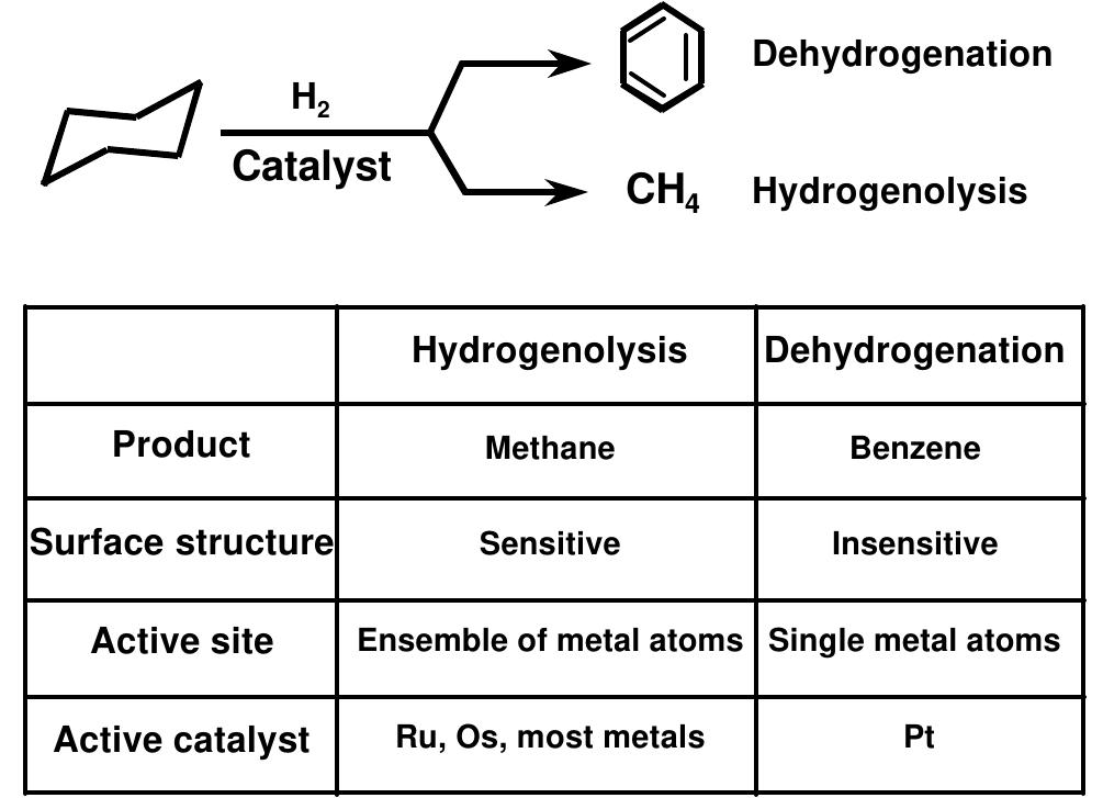
![Figure 7. Selectivity for cyclohexane dehydrogenation (to benzene) over hydrogenolysis (to methane) by sonochemically prepared Fe/Co alloys [23].](https://figures.academia-assets.com/109121385/figure_006.jpg)
![Figure 11. Catalytic activity of sonochemically prepared Mo,C compared to Pt [27]. Figure 10. TEM and electron microdiffraction of sonochemically prepared Mo,C.](https://figures.academia-assets.com/109121385/figure_008.jpg)
![Figure 22. The effect of ultrasonic irradiation of Cu powder slurries on the surface composition 50 min. sputter time is roughly 1 Um depth [78]. If the particles collide at a glancing angle, a mechanical removal of surface material results with a macroscopic smoothing (and at the atomic level, a microscopic roughening) of the surface (as shown in Figure 21), in analogy to lapidary ball milling. Especially for reactive metals that form oxide, nitride or carbonaceous coatings, the consequences to the reactivity of metal particles can be quite substantial [3, 4, 14, 76- 80]. Surface composition studies with depth profiling by Auger electron spectroscopy and by sputtered neutral mass spectrometry reveal that ultrasonic irradiation effectively removes surface oxide and other contaminating coatings [14, 76-80]. An example of such an analysis is shown in Figure 22. The removal of such passivating coatings can dramatically improve chemical reaction rates. The reactivity of clean metal surfaces also appears to be responsible for the greater tendency for heterogeneous sonochemical reactions to involve single electron transfer [81] rather than acid-base chemistry, which generally arises from surface sites of the oxide coatings.](https://figures.academia-assets.com/109121385/figure_012.jpg)
![Figure 16. Schematic of the disulfide crosslinking that holds the protein microspheres together. The mechanism responsible for microsphere formation is a combination of two acoustic phenomena: emulsification and cavitation. Ultrasonic emulsification creates the microscopic dispersion of the protein solution necessary to form the proteinaceous microspheres. Alone, however, emulsification is insufficient to produce long-lived microspheres. The long life of these microspheres comes from a sonochemical cross- linking of the protein shell. Chemical reactions requiring O; are critical in forming the microspheres. It has been known for some time that the primary products from the sonolysis of water are H, and HO, coming from the sonolysis of water yielding H and OH;; in the presence of On», the latter produces HO, [58]. Based on chemical trapping experiments, we established that the proteinaceous microspheres are held together by disulfide bonds between protein cysteine residues and that superoxide is the crosslinking agent, as shown schematically in Figure 16. The crosslinked shell of the microspheres is only about ten protein molecules thick, as shown in Figure 17.](https://figures.academia-assets.com/109121385/figure_010.jpg)
![Figure 5. Bulk and nanometer Energy Dispersive X-ray (EDX) analysis of Fe/Co alloys prepared sonochemically from Fe(CO)s and Co(CO)3NO [23]. Sonochemical techniques can also be used to prepare nanostructured alloys. We chose Fe/Co alloys as a demonstration case because Fe(CO); and Co(CO)3(NO) were readily available as precursors that are thermally stable at the modest bulk solution temperatures necessary for high volatility. The composition of the Fe-Co alloys can be controlled simply by changing the ratio of solution concentrations of the precursors; alloy compositions ranging from pure Fe to pure Co are readily obtained [23-25].](https://figures.academia-assets.com/109121385/figure_004.jpg)
![Figure 25. Effect of ultrasonic irradiation of Ni slurries in octane on its activity as a hydrogenation catalyst [3]. More impressive effects, however, have been reported [3], especially for hydrogenations and hydrosilations with Ni or Raney Ni powder. For example, as shown in Figure 25, the hydrogenation of alkenes by Ni powder is enormously enhanced by ultrasonic irradiation [76, 80]. This is not due to fragmentation of the solid: the surface area did not change significantly even after lengthy irradiation. There is, however, a very interesting effect on the surface morphology (Figures 19 and 21). Ultrasonic irradiation smoothes, at a macroscopic scale, the initially crystalline surface and causes agglomeration of small particles. Both effects are due to interparticle collisions caused by cavitation-induced shockwaves. AES revealed that there is a striking decrease in the thickness of the oxide coat after ultrasonic irradiation. It is the removal of this passivating layer that is responsible for the >10°-fold increase observed in catalytic activity.](https://figures.academia-assets.com/109121385/figure_015.jpg)
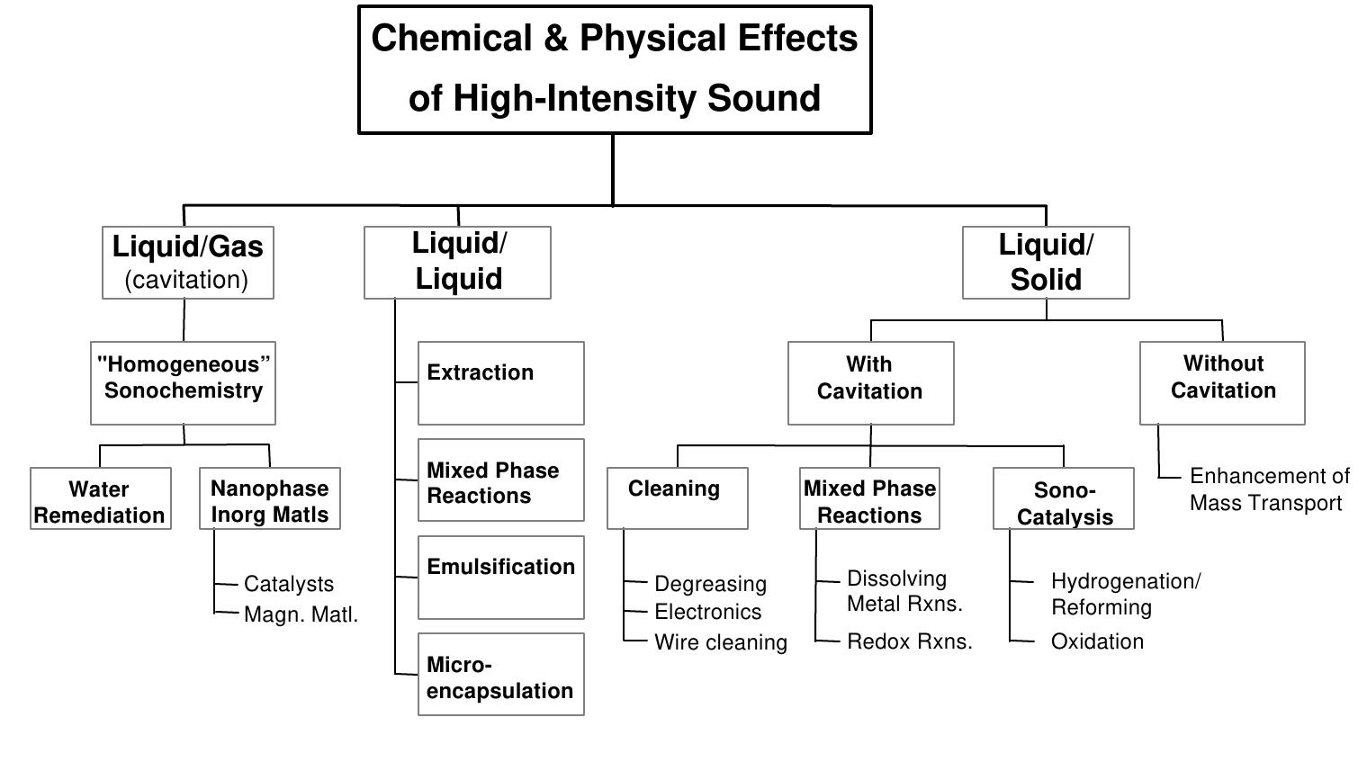
![Figure 2. Sonochemical synthesis of nanostructured materials. Using these extreme conditions, we have produced a variety of nanostructured and often amorphous metals, alloys, and carbides and examined their catalytic activity [1-4, 18-33]. Volatile organometallic compounds decompose inside a collapsing bubble, and the resulting metal atoms agglomerate to form nanostructured materials. Our sonochemical synthesis of nanostructured materials is also extremely versatile: various forms of nanophase materials can be generated simply by changing the reaction medium (Figure 2). When precursors are sonicated in high boiling alkanes, nanostructured metal powders are formed. If sonication occurs in the presence of a bulky or polymeric surface ligand, stable nanophase metal colloids are created. Sonication of the precursor in the presence of an inorganic support (silica or alumina) provides an alternative means of trapping the nanometer clusters. These nanoparticles trapped upon these supports produce active supported heterogeneous catalysts.](https://figures.academia-assets.com/109121385/figure_002.jpg)
![Figure 14. Catalytic activity for hydrodesulfurization of thiophene by various catalysts [33]. The observed turnover frequencies as a function of temperature for these catalysts are shown in Figure 14. The principal products detected by GC were the Cy hydrocarbons: butadiene, 1-butene, ftrans-2-butene, cis-2-butene, and butane. No partially hydrogenated thiophenes were detected, and lighter (C)-C3;) hydrocarbons accounted for less than 1% of the reaction products. The observed HDS activity order is MoS, (sonochemical) > RuS, (conventional) > ReS, (conventional) ~ Mo ,C (sonochemical'') > MoS; (conventional). The sonochemically prepared MoS, catalyzes the hydrodesulfurization (HDS) of thiophene with activities roughly five-fold better than conventional MoS, and comparable to those observed with RuS», one of the best commercial catalysts.](https://figures.academia-assets.com/109121385/figure_009.jpg)
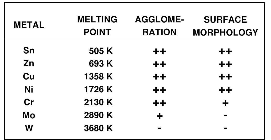
![Figure 23. Scanning electron micrograph of Cr, Mo, and W powder after ultrasonic irradiation of decane slurries under Ar. The melting points of these metals are 1857°, 2617°, and 3410°C, respectively [13]. In order to probe the conditions created during interparticle collisions in slurries irradiated with ultrasound, a series of transition metal powders were examined (Figure 23). Using the irradiation of Cr, Mo, and W powders in decane at 20 kHz and 50 W/cm’, one observes agglomeration and what appears to be localized melting for the first two metals, but not the third [13]; the melting points of these metals are 1857° for Cr, 2617° for Mo, and 3410°C for W. If one compiles a table of the effects of ultrasonic irradiation of slurries of different metal powders (Figure 24), one discovers that there is a break point in aggregation and surface deformations that occurs as the metal melting points increase. It appears that the effective transient temperature reached at the point of impact during interparticle collisions is roughly 3000°C. This effective local temperature has no direct connection with the temperatures inside the cavitating bubble, but they are another demonstration of the extreme conditions which ultrasound can create in an otherwise cold liquid.](https://figures.academia-assets.com/109121385/figure_013.jpg)
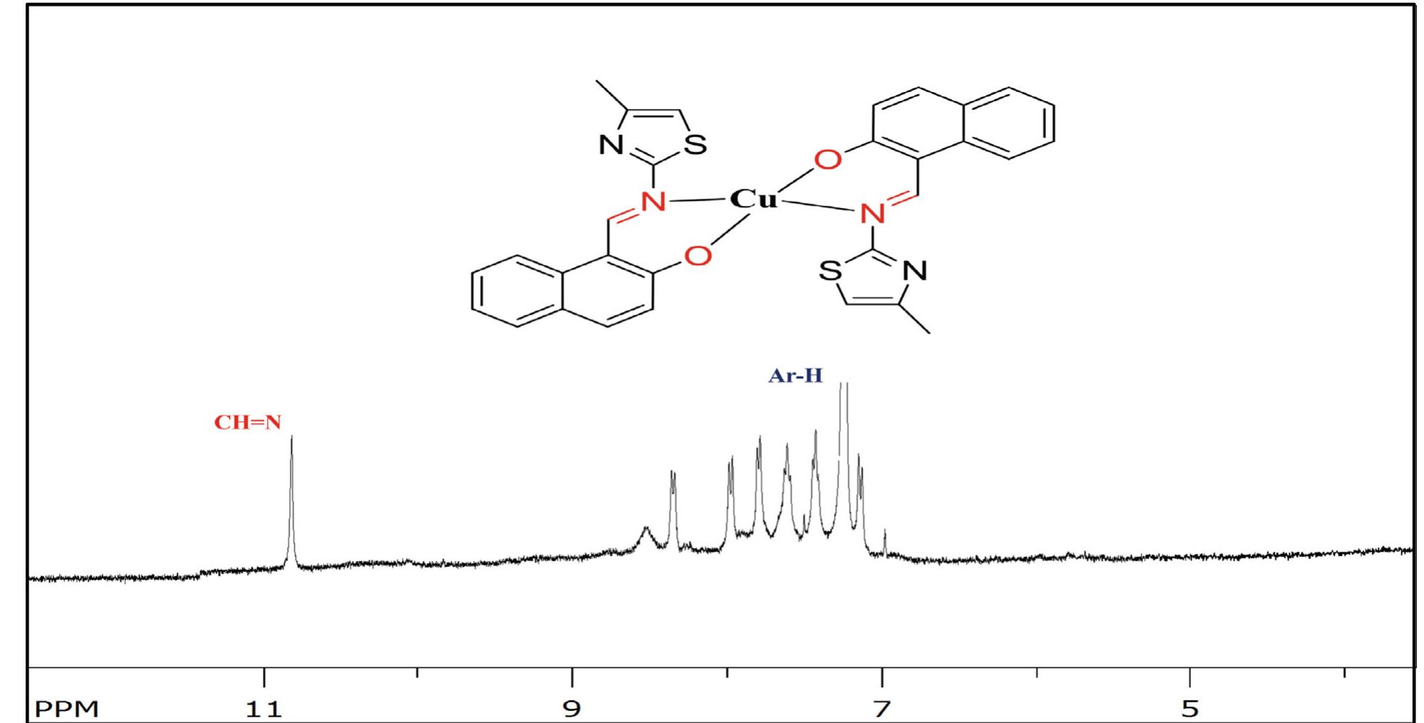
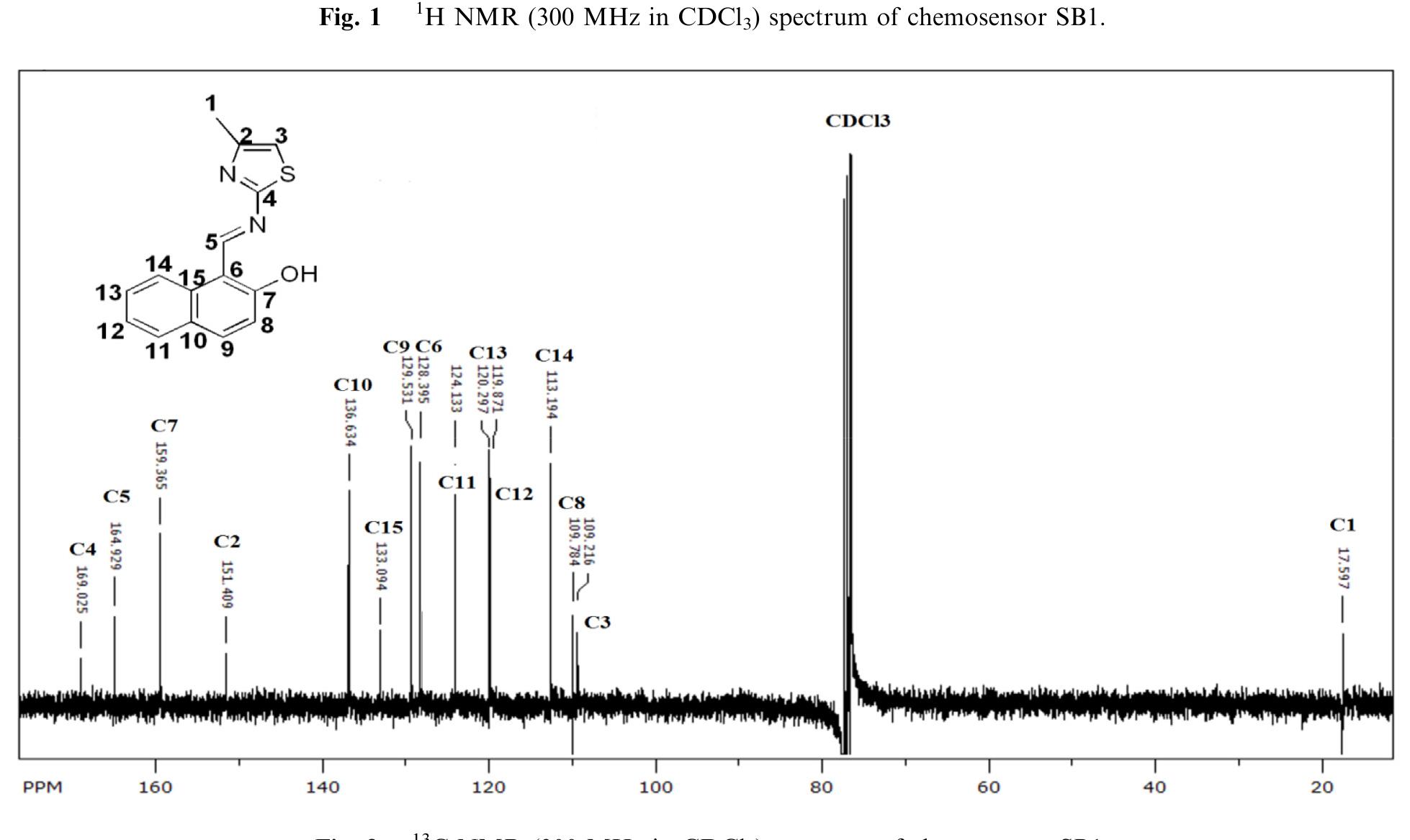
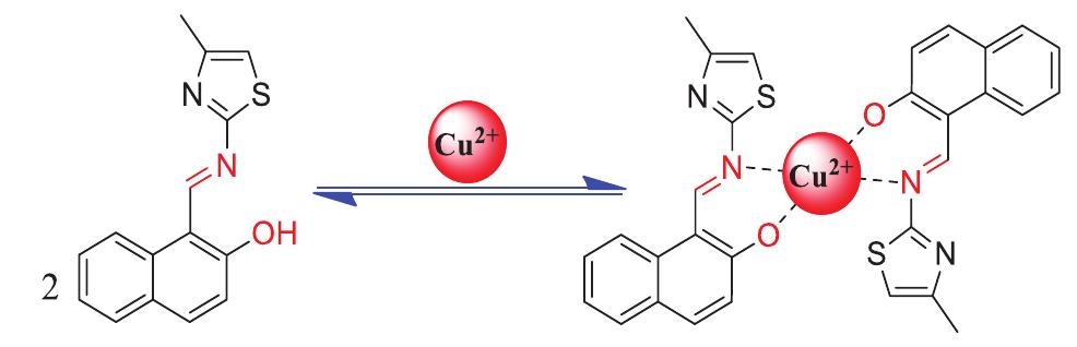
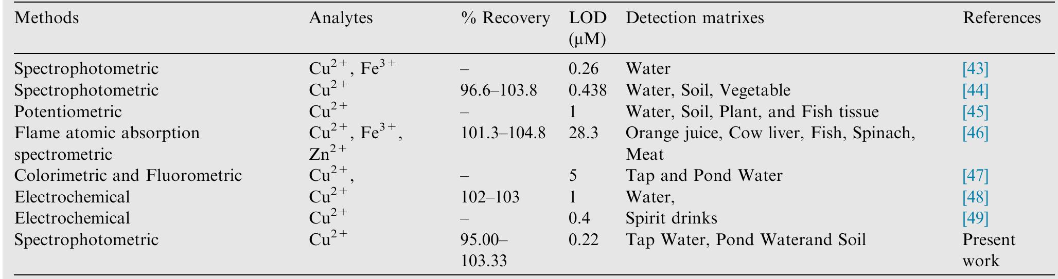
![Scheme 1 Synthetic route to chemosensor SBI. There is a growing demand to design and synthesize highly selective, sensitive, and low cost chemosensors for the detec- tion and determination of Cu** ions. Hence, the design and synthesis of a spectrophotometric chemosensor for the detec- tion and determination of Cu’ * ions would be the most attrac- tive [28-30]. The N-, O- and S- containing compounds especially Schiff bases which can act as ligands, are regarded as organic chemosensors with higher sensitivity, selectivity, and low manufacturing costs. These ligands can readily form metal complexes with various metal ions and stabilize them in a different oxidation states and give measurable analytical signals [24]. Herein, we report a facile, selective, sensitive, cost-effective, and colorimetric chemosensor SB1 to determine the trace amount of Cu** ions in different environmental and agricultural samples. The chemosensor SB1 was synthesized by the condensation reaction of 2-amino-4-methyl thiazole and 2- hydroxy-1- naphthaldehyde in methanol as solvent (Scheme 1). The chemosensor SBI can help to detect Cu?* ions via com-](https://figures.academia-assets.com/107612784/figure_001.jpg)
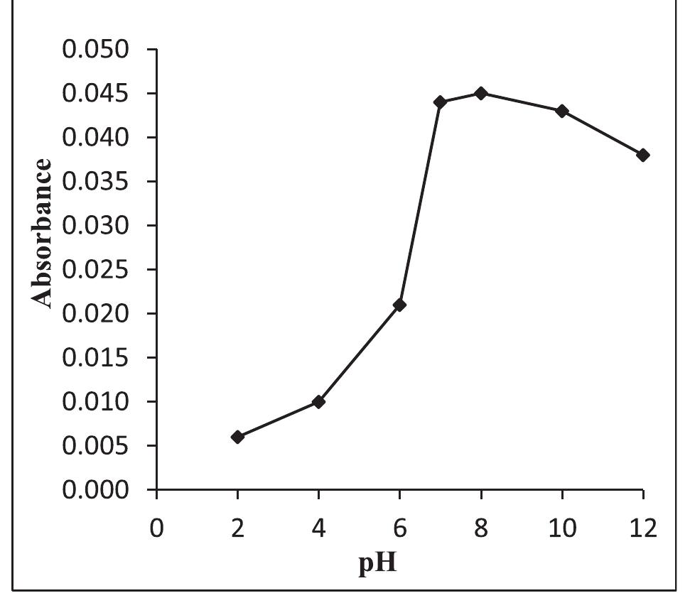
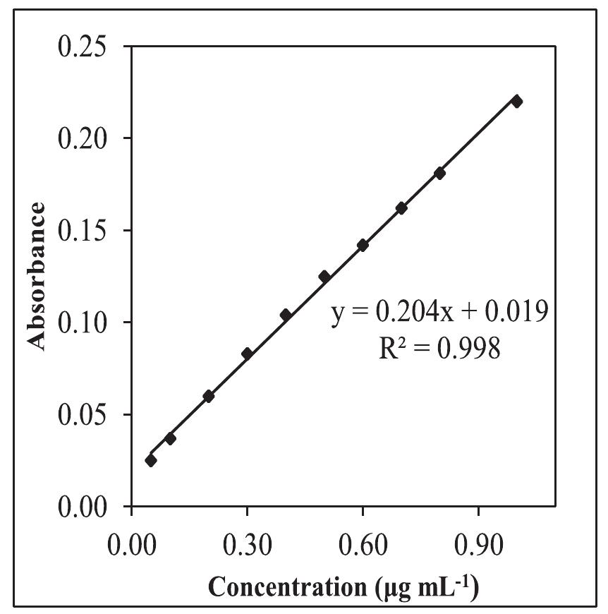
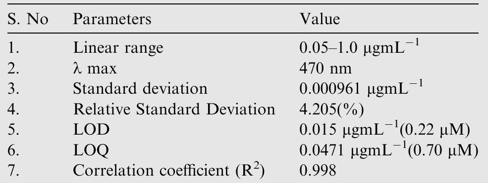
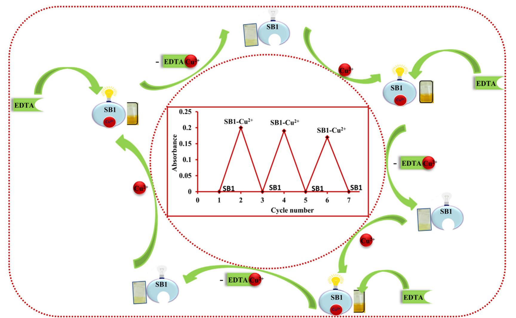
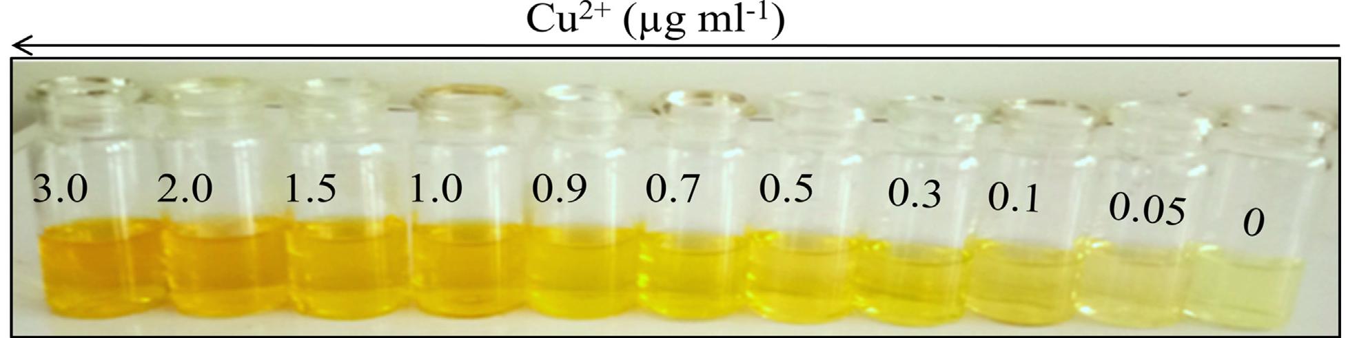
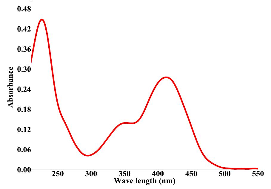
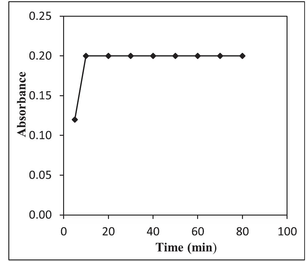
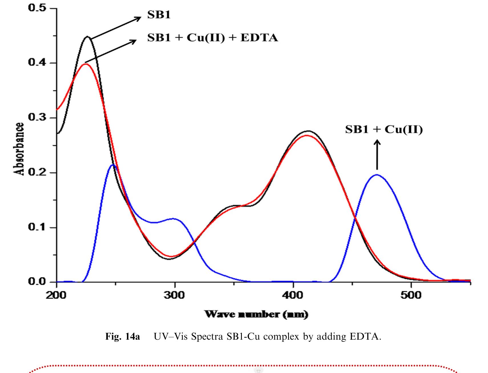
![Fig.7 The absorption spectral changes of chemosensor SB1(5 pg mL~') in the MeOH-Water system (8/2 v/v) after the addition of 0.05- 1 pg mL! of C(I) ions. The reversibility of the binding between chemosensor SB1 and Cu’* ion was performed using EDTA as a chelating agent [41]. The effect of time on the stability of the Cu-SB1 complex was also investigated (up to 80 min). The reaction is very fast and a con-](https://figures.academia-assets.com/107612784/figure_008.jpg)