US20220097925A1 - Lid With Locking Feature - Google Patents
Lid With Locking Feature Download PDFInfo
- Publication number
- US20220097925A1 US20220097925A1 US17/482,767 US202117482767A US2022097925A1 US 20220097925 A1 US20220097925 A1 US 20220097925A1 US 202117482767 A US202117482767 A US 202117482767A US 2022097925 A1 US2022097925 A1 US 2022097925A1
- Authority
- US
- United States
- Prior art keywords
- dispenser
- central wall
- lid
- panel
- locking
- Prior art date
- Legal status (The legal status is an assumption and is not a legal conclusion. Google has not performed a legal analysis and makes no representation as to the accuracy of the status listed.)
- Granted
Links
- 238000000034 method Methods 0.000 claims description 14
- 235000013361 beverage Nutrition 0.000 description 14
- 239000007788 liquid Substances 0.000 description 10
- 239000000463 material Substances 0.000 description 9
- 235000016213 coffee Nutrition 0.000 description 5
- 235000013353 coffee beverage Nutrition 0.000 description 5
- 230000008901 benefit Effects 0.000 description 4
- 239000012530 fluid Substances 0.000 description 4
- 244000269722 Thea sinensis Species 0.000 description 3
- 230000035622 drinking Effects 0.000 description 3
- 239000000123 paper Substances 0.000 description 3
- 239000011087 paperboard Substances 0.000 description 3
- 235000013616 tea Nutrition 0.000 description 3
- CDBYLPFSWZWCQE-UHFFFAOYSA-L Sodium Carbonate Chemical compound [Na+].[Na+].[O-]C([O-])=O CDBYLPFSWZWCQE-UHFFFAOYSA-L 0.000 description 2
- 244000299461 Theobroma cacao Species 0.000 description 2
- 235000009470 Theobroma cacao Nutrition 0.000 description 2
- 235000019987 cider Nutrition 0.000 description 2
- 239000004927 clay Substances 0.000 description 2
- 239000011248 coating agent Substances 0.000 description 2
- 238000000576 coating method Methods 0.000 description 2
- 235000020965 cold beverage Nutrition 0.000 description 2
- 235000013305 food Nutrition 0.000 description 2
- 239000003292 glue Substances 0.000 description 2
- 235000012171 hot beverage Nutrition 0.000 description 2
- 238000012986 modification Methods 0.000 description 2
- 230000004048 modification Effects 0.000 description 2
- 238000007639 printing Methods 0.000 description 2
- 238000000926 separation method Methods 0.000 description 2
- 239000007787 solid Substances 0.000 description 2
- 230000007704 transition Effects 0.000 description 2
- 230000003313 weakening effect Effects 0.000 description 2
- 241001180747 Hottea Species 0.000 description 1
- 239000000853 adhesive Substances 0.000 description 1
- 230000001070 adhesive effect Effects 0.000 description 1
- 230000004075 alteration Effects 0.000 description 1
- 230000004888 barrier function Effects 0.000 description 1
- 238000005452 bending Methods 0.000 description 1
- 235000014171 carbonated beverage Nutrition 0.000 description 1
- 239000011111 cardboard Substances 0.000 description 1
- 230000000295 complement effect Effects 0.000 description 1
- 230000006835 compression Effects 0.000 description 1
- 238000007906 compression Methods 0.000 description 1
- 238000010276 construction Methods 0.000 description 1
- 230000000994 depressogenic effect Effects 0.000 description 1
- -1 e.g. Substances 0.000 description 1
- 238000004049 embossing Methods 0.000 description 1
- 230000001815 facial effect Effects 0.000 description 1
- 210000005224 forefinger Anatomy 0.000 description 1
- 235000011389 fruit/vegetable juice Nutrition 0.000 description 1
- 239000007789 gas Substances 0.000 description 1
- 238000010348 incorporation Methods 0.000 description 1
- 238000001746 injection moulding Methods 0.000 description 1
- 235000015122 lemonade Nutrition 0.000 description 1
- 235000013336 milk Nutrition 0.000 description 1
- 239000008267 milk Substances 0.000 description 1
- 210000004080 milk Anatomy 0.000 description 1
- 235000020166 milkshake Nutrition 0.000 description 1
- 239000000203 mixture Substances 0.000 description 1
- 229920000642 polymer Polymers 0.000 description 1
- 235000013570 smoothie Nutrition 0.000 description 1
- 235000014214 soft drink Nutrition 0.000 description 1
- 238000003856 thermoforming Methods 0.000 description 1
- 210000003813 thumb Anatomy 0.000 description 1
- 239000002966 varnish Substances 0.000 description 1
- XLYOFNOQVPJJNP-UHFFFAOYSA-N water Substances O XLYOFNOQVPJJNP-UHFFFAOYSA-N 0.000 description 1
Images


Classifications
-
- B—PERFORMING OPERATIONS; TRANSPORTING
- B65—CONVEYING; PACKING; STORING; HANDLING THIN OR FILAMENTARY MATERIAL
- B65D—CONTAINERS FOR STORAGE OR TRANSPORT OF ARTICLES OR MATERIALS, e.g. BAGS, BARRELS, BOTTLES, BOXES, CANS, CARTONS, CRATES, DRUMS, JARS, TANKS, HOPPERS, FORWARDING CONTAINERS; ACCESSORIES, CLOSURES, OR FITTINGS THEREFOR; PACKAGING ELEMENTS; PACKAGES
- B65D43/00—Lids or covers for rigid or semi-rigid containers
- B65D43/02—Removable lids or covers
- B65D43/0202—Removable lids or covers without integral tamper element
- B65D43/0204—Removable lids or covers without integral tamper element secured by snapping over beads or projections
- B65D43/0212—Removable lids or covers without integral tamper element secured by snapping over beads or projections only on the outside, or a part turned to the outside, of the mouth
-
- B—PERFORMING OPERATIONS; TRANSPORTING
- B65—CONVEYING; PACKING; STORING; HANDLING THIN OR FILAMENTARY MATERIAL
- B65D—CONTAINERS FOR STORAGE OR TRANSPORT OF ARTICLES OR MATERIALS, e.g. BAGS, BARRELS, BOTTLES, BOXES, CANS, CARTONS, CRATES, DRUMS, JARS, TANKS, HOPPERS, FORWARDING CONTAINERS; ACCESSORIES, CLOSURES, OR FITTINGS THEREFOR; PACKAGING ELEMENTS; PACKAGES
- B65D2543/00—Lids or covers essentially for box-like containers
- B65D2543/00009—Details of lids or covers for rigid or semi-rigid containers
- B65D2543/00018—Overall construction of the lid
- B65D2543/00046—Drinking-through lids
-
- B—PERFORMING OPERATIONS; TRANSPORTING
- B65—CONVEYING; PACKING; STORING; HANDLING THIN OR FILAMENTARY MATERIAL
- B65D—CONTAINERS FOR STORAGE OR TRANSPORT OF ARTICLES OR MATERIALS, e.g. BAGS, BARRELS, BOTTLES, BOXES, CANS, CARTONS, CRATES, DRUMS, JARS, TANKS, HOPPERS, FORWARDING CONTAINERS; ACCESSORIES, CLOSURES, OR FITTINGS THEREFOR; PACKAGING ELEMENTS; PACKAGES
- B65D2543/00—Lids or covers essentially for box-like containers
- B65D2543/00009—Details of lids or covers for rigid or semi-rigid containers
- B65D2543/00018—Overall construction of the lid
- B65D2543/00064—Shape of the outer periphery
- B65D2543/00074—Shape of the outer periphery curved
- B65D2543/00092—Shape of the outer periphery curved circular
-
- B—PERFORMING OPERATIONS; TRANSPORTING
- B65—CONVEYING; PACKING; STORING; HANDLING THIN OR FILAMENTARY MATERIAL
- B65D—CONTAINERS FOR STORAGE OR TRANSPORT OF ARTICLES OR MATERIALS, e.g. BAGS, BARRELS, BOTTLES, BOXES, CANS, CARTONS, CRATES, DRUMS, JARS, TANKS, HOPPERS, FORWARDING CONTAINERS; ACCESSORIES, CLOSURES, OR FITTINGS THEREFOR; PACKAGING ELEMENTS; PACKAGES
- B65D2543/00—Lids or covers essentially for box-like containers
- B65D2543/00009—Details of lids or covers for rigid or semi-rigid containers
- B65D2543/00444—Contact between the container and the lid
- B65D2543/00481—Contact between the container and the lid on the inside or the outside of the container
- B65D2543/0049—Contact between the container and the lid on the inside or the outside of the container on the inside, or a part turned to the inside of the mouth of the container
- B65D2543/00527—NO contact
-
- B—PERFORMING OPERATIONS; TRANSPORTING
- B65—CONVEYING; PACKING; STORING; HANDLING THIN OR FILAMENTARY MATERIAL
- B65D—CONTAINERS FOR STORAGE OR TRANSPORT OF ARTICLES OR MATERIALS, e.g. BAGS, BARRELS, BOTTLES, BOXES, CANS, CARTONS, CRATES, DRUMS, JARS, TANKS, HOPPERS, FORWARDING CONTAINERS; ACCESSORIES, CLOSURES, OR FITTINGS THEREFOR; PACKAGING ELEMENTS; PACKAGES
- B65D2543/00—Lids or covers essentially for box-like containers
- B65D2543/00009—Details of lids or covers for rigid or semi-rigid containers
- B65D2543/00444—Contact between the container and the lid
- B65D2543/00481—Contact between the container and the lid on the inside or the outside of the container
- B65D2543/00537—Contact between the container and the lid on the inside or the outside of the container on the outside, or a part turned to the outside of the mouth of the container
-
- B—PERFORMING OPERATIONS; TRANSPORTING
- B65—CONVEYING; PACKING; STORING; HANDLING THIN OR FILAMENTARY MATERIAL
- B65D—CONTAINERS FOR STORAGE OR TRANSPORT OF ARTICLES OR MATERIALS, e.g. BAGS, BARRELS, BOTTLES, BOXES, CANS, CARTONS, CRATES, DRUMS, JARS, TANKS, HOPPERS, FORWARDING CONTAINERS; ACCESSORIES, CLOSURES, OR FITTINGS THEREFOR; PACKAGING ELEMENTS; PACKAGES
- B65D2543/00—Lids or covers essentially for box-like containers
- B65D2543/00009—Details of lids or covers for rigid or semi-rigid containers
- B65D2543/00444—Contact between the container and the lid
- B65D2543/00592—Snapping means
- B65D2543/00601—Snapping means on the container
- B65D2543/00611—Profiles
- B65D2543/00638—Rolled edge
-
- B—PERFORMING OPERATIONS; TRANSPORTING
- B65—CONVEYING; PACKING; STORING; HANDLING THIN OR FILAMENTARY MATERIAL
- B65D—CONTAINERS FOR STORAGE OR TRANSPORT OF ARTICLES OR MATERIALS, e.g. BAGS, BARRELS, BOTTLES, BOXES, CANS, CARTONS, CRATES, DRUMS, JARS, TANKS, HOPPERS, FORWARDING CONTAINERS; ACCESSORIES, CLOSURES, OR FITTINGS THEREFOR; PACKAGING ELEMENTS; PACKAGES
- B65D2543/00—Lids or covers essentially for box-like containers
- B65D2543/00009—Details of lids or covers for rigid or semi-rigid containers
- B65D2543/00444—Contact between the container and the lid
- B65D2543/00592—Snapping means
- B65D2543/00601—Snapping means on the container
- B65D2543/00675—Periphery concerned
- B65D2543/00685—Totality
-
- B—PERFORMING OPERATIONS; TRANSPORTING
- B65—CONVEYING; PACKING; STORING; HANDLING THIN OR FILAMENTARY MATERIAL
- B65D—CONTAINERS FOR STORAGE OR TRANSPORT OF ARTICLES OR MATERIALS, e.g. BAGS, BARRELS, BOTTLES, BOXES, CANS, CARTONS, CRATES, DRUMS, JARS, TANKS, HOPPERS, FORWARDING CONTAINERS; ACCESSORIES, CLOSURES, OR FITTINGS THEREFOR; PACKAGING ELEMENTS; PACKAGES
- B65D2543/00—Lids or covers essentially for box-like containers
- B65D2543/00009—Details of lids or covers for rigid or semi-rigid containers
- B65D2543/00444—Contact between the container and the lid
- B65D2543/00592—Snapping means
- B65D2543/00712—Snapping means on the lid
- B65D2543/00722—Profiles
- B65D2543/00759—Flange or lip
-
- B—PERFORMING OPERATIONS; TRANSPORTING
- B65—CONVEYING; PACKING; STORING; HANDLING THIN OR FILAMENTARY MATERIAL
- B65D—CONTAINERS FOR STORAGE OR TRANSPORT OF ARTICLES OR MATERIALS, e.g. BAGS, BARRELS, BOTTLES, BOXES, CANS, CARTONS, CRATES, DRUMS, JARS, TANKS, HOPPERS, FORWARDING CONTAINERS; ACCESSORIES, CLOSURES, OR FITTINGS THEREFOR; PACKAGING ELEMENTS; PACKAGES
- B65D2543/00—Lids or covers essentially for box-like containers
- B65D2543/00009—Details of lids or covers for rigid or semi-rigid containers
- B65D2543/00444—Contact between the container and the lid
- B65D2543/00592—Snapping means
- B65D2543/00712—Snapping means on the lid
- B65D2543/00787—Periphery concerned
- B65D2543/00796—Totality
Definitions
- the present disclosure relates to lids for containers (e.g., beverage cups) for containing and/or dispensing fluids (e.g., beverages). More specifically, the disclosure is generally directed to a lid having a dispenser and a locking feature for one or more portions thereof.
- containers e.g., beverage cups
- dispensing fluids e.g., beverages
- one aspect of the disclosure is directed to a lid for a container.
- the lid comprises a central wall and a dispenser comprising a dispenser flap hingedly connected to the central wall and moveable between a closed configuration and an open configuration at least partially exposing a dispenser opening in the central wall.
- the dispenser further can include a projection extending from the dispenser flap.
- the lid further comprises a locking feature for maintaining the dispenser in the open configuration.
- the locking feature can comprise a locking recess in the central wall for at least partially receiving the projection.
- the dispenser opening can be located on a centerline of the lid, and the locking recess can be spaced away from the centerline of the lid.
- a method of forming a lid for a container comprises forming a central wall, a dispenser, and a locking feature for maintaining the dispenser in an open configuration.
- the dispenser comprises a dispenser flap hingedly connected to the central wall and moveable between a closed configuration and the open configuration at least partially exposing a dispenser opening in the central wall.
- the dispenser further can comprise a projection extending from the dispenser flap.
- the dispenser opening can be located on a centerline of the lid.
- the locking feature can comprise a locking recess in the central wall for at least partially receiving the projection.
- the forming the central wall, the dispenser, and the locking feature can comprise forming the locking recess at a location spaced away from the centerline of the lid.
- a container assembly comprises a lid engaged with a container.
- the lid comprises a central wall, an annular skirt extending downwardly with respect to the central wall and along at least a portion of the container, an annular ridge extending upwardly from the central wall, and a dispenser comprising a dispenser flap hingedly connected to the central wall and a projection extending from the dispenser flap.
- the dispenser flap can extend along at least a portion of a centerline of the lid when the dispenser flap is in a closed configuration.
- the lid further can comprise a locking feature for maintaining the dispenser in an open configuration.
- the locking feature can comprise a locking recess for at least partially receiving the projection.
- the locking recess can be spaced away from the centerline of the lid.
- a method of forming a container assembly comprises obtaining a lid comprising a central wall, an annular skirt extending downwardly with respect to the central wall, an annular ridge extending upwardly from the central wall, and a dispenser comprising a dispenser flap hingedly connected to the central wall and a projection extending from the dispenser flap.
- the dispenser flap can extend along at least a portion of a centerline of the lid when the dispenser flap is in a closed configuration.
- the lid further can comprise a locking feature for maintaining the dispenser in an open configuration.
- the locking feature can comprise a locking recess for at least partially receiving the projection.
- the locking recess can be spaced away from the centerline of the lid.
- the method further can comprise attaching the lid to an upper portion of the container so that the annular skirt extends along at least a portion of the container.
- FIG. 1 is a plan view of a lid with a dispensing feature in a closed configuration according to an exemplary embodiment of the disclosure.
- FIG. 2 is a perspective view of a container suitable for engagement with the lid of FIG. 1 .
- FIG. 3 is a rear view of the lid of FIG. 1 .
- FIG. 4 is a side view of the lid of FIG. 1 .
- FIG. 5 is a perspective view of a container assembly with the container of FIG. 2 engaged with the lid of FIG. 1 in the closed configuration.
- FIG. 6 is a perspective view of the container assembly of FIG. 5 with the dispensing feature of the lid in an open configuration.
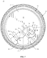
- FIG. 7 is a top plan view of the lid of FIG. 1 with the dispensing feature in the open configuration of FIG. 6 .
- Containers and lids according to the present disclosure can cooperate to accommodate fluids, e.g., liquid or semi-liquid beverages that can include one or more solid components, of different sizes and compositions.
- fluids e.g., liquid or semi-liquid beverages that can include one or more solid components, of different sizes and compositions.
- a container for tepid, warm, hot, cool, cold, and/or at least partially frozen beverages e.g., hot coffee, hot tea, hot cocoa, hot cider, water, soda, iced coffee, cold brew coffee, blended ice beverages (such as smoothies, slush beverages, milkshakes, etc.), iced tea, lemonade, and other flavored or unflavored beverages (e.g., soft drinks), to name a few.
- the containers and lids described herein can contain different types of beverages having any suitable temperature and/or products containing one or more food items without departing from the disclosure.
- lids can be formed of a plastic material (e.g., a food grade polymer) and containers can be formed from blanks (e.g., paperboard blanks).
- lids can be formed by thermoforming and/or injection molding and/or any other suitable forming method.
- Containers can be formed from the blanks by overlapping multiple portions, panels, and/or end flaps. Such portions, panels, and/or end flaps may be designated herein in terms relative to one another, e.g., “first,” “second,” “third,” etc., in sequential or non-sequential reference, without departing from the disclosure.
- the lids could be formed from paper products and/or the containers could be formed from plastic materials without departing from the disclosure.
- the terms “inner,” “interior,” “outer,” “exterior,” “front,” “back,” “rear,” “side,” “lower,” “bottom,” “upper,” and “top” indicate orientations determined in relation to fully erected and upright containers.
- FIG. 1 illustrates a drinking lid 10 for attachment to a container C ( FIG. 2 ), such as a drinking cup, so that the combined lid 10 and container C form a container assembly 100 ( FIGS. 5 and 6 ).
- the container C can be configured for holding cold and/or hot beverages and/or other suitable items.
- the container can hold hot beverages (e.g., tea, coffee, hot cocoa, hot cider and/or other suitable beverages).
- the container can hold the container can hold cold beverages (e.g., soda, juice, milk, tea, coffee, cocktails, and/or other suitable beverages), with or without ice.
- the container C can have a bottom wall (not shown) and a sidewall SW extending around an interior of the container C for holding the beverage or any suitable liquid.
- the container C further can include a rim R for receiving the lid 10 at a top end of the sidewall SW.
- the lid 10 can be configured for use with a container having a different configuration without departing from the disclosure. As described herein, the lid 10 can be attached to or otherwise engaged with the container C to provide a container assembly.
- the lid 10 can include a top or central wall 12 , an annular ridge 13 extending upwardly from the central wall 12 , a flange or annular skirt 14 extending downwardly from the central wall 12 and the annular ridge 13 , and an opening feature or dispenser 16 formed in the central wall 12 .
- the annular ridge 13 and the annular skirt 14 can each have a generally circular arrangement about a center point P.
- a centerline CL of the lid 10 can extend through the center point P and the dispenser 16 , as shown.
- the centerline CL can extend through a center of the dispenser 16 .
- the centerline CL can intersect a portion 17 of the annular ridge 13 along which a user may position his or her mouth to retrieve fluids from the interior of the container C through the dispenser 16 , as described further herein.
- the central wall 12 can be recessed below the annular ridge 13 so as to form an interior space or ponding area so that any liquid on the top side of the lid 10 can collect in an area that is spaced away from the dispenser 16 .
- the central wall 12 also can include indicators (not shown) that can be selectively actuated (e.g., depressed) or marked to indicate the type of beverage that is contained in the container C.
- the central wall 12 optionally can include a vent (not shown), which can allow gases (e.g., from carbonated beverages) to escape from the interior of the container C and/or can allow air to enter the interior when liquids are dispensed through the dispenser 16 .
- Such indicators and/or a vent could be omitted.
- the central wall 12 , the annular ridge 13 , and/or the annular skirt could be omitted or could be otherwise shaped, arranged, positioned, and/or configured without departing from the disclosure.
- the dispenser 16 can include a dispenser panel 18 supported on the central wall 12 and a dispenser flap 20 hingedly/foldably connected to the dispenser panel 18 along a hinge 22 .
- the hinge can extend in an oblique direction with respect to the centerline CL.
- the hinge 22 can be spaced apart from the centerline CL.
- the dispenser panel 18 can have a side portion 18 a extending upwardly from a base panel 21 of the central wall 12 and a top portion 18 b , which can extend obliquely (e.g., so that the top portion 18 b is slanted downwardly from the annular ridge 13 toward the center point P of the lid 10 ).
- the dispenser panel 18 can be considered a portion of the central wall 12 such that the dispenser flap 20 is hingedly connected to the central wall 12 at the hinge 22 .
- the dispenser flap 20 can be separable from the dispenser panel 18 along a cut 23 .
- the cut 23 can include a generally circular or ovoid portion 23 a , and a pair of oblique cuts 23 b extending obliquely from endpoints of the ovoid portion 23 a relative to the centerline CL.
- the cut 23 can include one or more lines of weakness (e.g., a partial cut, perforation line, tear line, a cut line with one or more nicks, etc.) that is suitable for allowing the dispenser flap 20 to separate from the dispenser panel 18 when the dispenser 16 is actuated, as described further herein.
- the hinge 22 can be a line or region of weakening that intersects the cut 23 (e.g., the portions 23 b of the cut 23 ) and that extends generally obliquely relative to the centerline CL.
- the dispenser panel 18 can include a downwardly-extending face or step 19 along which the hinge 22 is at least partially positioned. It will be understood that the hinge 22 and/or the cut 23 could have an alternative configuration without departing from the disclosure.
- the dispenser 16 further can include a protuberance or projection 24 with a top surface 26 , a front surface 28 , a rear surface 29 , and side surfaces 30 extending between the top surface 26 and the front and rear surfaces 28 , 29 (shown best in FIGS. 3-5 ).
- the projection 24 can include on or more regions of transition, e.g., bevels, ledges, steps, curves, chamfers, etc., between the respective surfaces.
- one or more of the surfaces 26 , 28 , 29 , 30 can include one or more curved or angled portions and/or surface features such as notches, recesses, lips, ledges, etc.
- the dispenser flap 20 and the projection 24 can be considered a tab.
- the projection 24 is spaced from the cut 23 in the dispenser flap 20 so that a portion of the dispenser flap 20 extends around the perimeter of the projection 24 .
- the projection 24 is supported on the dispenser flap 20 so as to move in conjunction with the dispenser flap 20 .
- the dispenser flap 20 and/or the projection 24 could be omitted or could be otherwise shaped, arranged, positioned, and/or configured without departing from the disclosure.
- a locking panel 32 can be supported on the central wall 12 of the lid 10 and positioned adjacent and/or abutting the dispenser panel 18 .
- the locking panel 32 can be supported above the central wall 12 and below the dispenser panel 18 , e.g., intersecting the step 19 of the dispenser panel 18 such that the dispenser panel 18 , the locking panel 32 , and the base panel 21 of the central wall 12 can have a stepped or staggered arrangement.
- the dispenser panel 18 and the locking panel 32 can extend along at least a portion of the annular ridge 13 .
- one or more regions of transition can be provided between respective portions of the dispenser panel 18 , the locking panel 32 , and the base panel 21 of the central wall 12 , e.g., bevels, ledges, steps, curves, chamfers, etc.
- the lid 10 can include a recessed area defined along at least the base panel 21 (e.g., for catching spilled liquid).
- one or more of the dispenser panel 18 , the locking panel 32 , and the base panel 21 can be provided in a coplanar relationship. While the dispenser panel 18 and locking panel 32 have been described as panels supported above the base panel 21 of the central wall 12 , it will be understood that one or both of the dispenser panel 18 and the locking panel 32 can be considered raised portions of the central wall 12 without departing from the disclosure.
- the locking panel 32 can include a locking recess 34 that is an at least partially recessed portion of the locking panel 32 so as to have the form of, for example, a notch, divot, catch, etc.
- the locking recess 34 extending in the locking panel 32 of the central wall 12 can have a generally complementary configuration to the projection 24 extending from the dispenser flap 20 , e.g., so as to have surfaces generally corresponding to the surfaces 26 , 28 , 29 , 30 of the projection 24 extending downwardly from the locking panel 32 .
- the locking recess 34 can have a generally triangular or wedge-shaped recessed configuration.
- the dispenser 16 is in a closed configuration wherein the dispenser flap 20 engages, abuts, and/or is closely spaced from the dispenser panel 18 at the cut 23 to help prevent or reduce spilling or splashing of liquids in the container C through the dispenser 16 when the dispenser 16 is in a closed position.
- the locking recess 34 and at least a portion of the projection 24 /dispenser flap 20 are locking features that can maintain the dispenser flap 20 in an actuated/open position and that are spaced away from the dispenser panel 18 so as to expose a dispenser opening 40 ( FIGS. 6 and 7 ) that is at least partially surrounded by an edge 42 formed along the cut 23 .
- a dispenser opening 40 FIGS. 6 and 7
- Such dispenser opening 40 provides access to the interior of the container C and a passage through the dispenser 16 so that a user can pour or retrieve fluid contents of the container C therethrough, as described further herein.
- the dispenser 16 and/or locking features could be otherwise shaped, arranged, positioned, and/or configured without departing from the disclosure.
- a user in operation, can at least partially fill a container, e.g., container C ( FIG. 2 ) with liquid and/or solids and can engage the lid 10 with the top portion of the container C so that the container C and the lid 10 cooperate to enclose an interior space thereof (not shown) and form the container assembly 100 ( FIGS. 5 and 6 ).
- a container e.g., container C ( FIG. 2 )
- the lid 10 can engage the lid 10 with the top portion of the container C so that the container C and the lid 10 cooperate to enclose an interior space thereof (not shown) and form the container assembly 100 ( FIGS. 5 and 6 ).
- the skirt 14 includes an internal annular groove 36 extending along the annular ridge 13 and a plurality of inwardly-extending protrusions 38 spaced along the circumference of the skirt 14 ( FIGS. 3-6 ).
- the protrusions 38 have upper surfaces that form a lower portion of the annular groove 36 , and the upper surfaces of the protrusions 38 can be curved and/or sloped.
- the downward pressure on the lid 10 can cause the rim R to push outwardly on the sloped surfaces of the protrusions 38 , causing the skirt 14 to pivot (e.g., bend, flex, and/or fold) outwardly so that the protrusions 38 can move past the rim R as the lid 10 is pushed downwardly.
- the lid 10 can snap onto the rim R as the protrusions 38 move past the rim R and the rim R is engaged in the annular groove 36 .
- the skirt 14 can move back to its original position with the protrusions 38 engaged with an underside of the rim R at their upper surfaces.
- the container assembly 100 is formed when the lid 10 is engaged with the container C.
- the annular skirt 14 can extend downwardly with respect to the central wall 12 along a portion (e.g., an upper portion) of the container C in the container assembly 100 .
- the skirt 14 could be omitted or could be otherwise shaped, arranged, positioned, and/or configured without departing from the disclosure.
- the lid 10 could be otherwise configured to engage the container C.
- the dispenser flap 20 in the closed position of FIGS. 1 and 3-5 can help prevent splashing and/or spilling of liquid from the interior of the container.
- the dispenser 16 can be actuated to an open or dispensing configuration (e.g., for drinking a beverage through the dispenser 16 ).
- the dispenser 16 can be actuated by engagement of the projection 24 by a user, for example, contact with a user's thumb and/or forefinger, to cause at least partial separation of the dispenser flap 20 from the dispenser panel 18 at the cut 23 . Further movement/urging of the projection 24 by the user can cause the dispenser flap 20 and the projection 24 carried thereon to fold/pivot/flex at the hinge 22 in the direction of the arrow A 1 ( FIG.
- a user can pivot/fold/flex the dispenser flap 20 to position the projection 24 at least partially within the locking recess 34 , and one or more of the surfaces 26 , 28 , 29 , 30 of the projection 24 can engage a corresponding surface of the locking recess 34 to maintain the projection 24 in a position so as to be at least partially received by the locking recess 34 .
- such engagement of the projection 24 and the locking recess 34 can be facilitated by an interference fit, friction fit, compression of the projection 24 by the locking recess 34 , etc.
- the separation of the dispenser flap 20 from the dispenser panel 18 along the cut 23 forms the dispenser opening 40 with the edge 42 of the dispenser panel 18 and the hinge 22 extending along the opening 40 . Accordingly, a user can access the beverage or other liquid in the interior of the container C through the dispenser opening 40 .
- the dispenser 16 can be closed by reversing the steps outlined above, e.g., by disengaging the projection 24 /dispenser flap 20 from the locking recess 34 (e.g., by pulling upwardly on the dispenser flap 20 ) and pivoting/folding/flexing the dispenser flap 20 at the hinge 22 toward the opening 40 and at least partially covering the dispenser opening 40 with the dispenser flap 20 .
- the oblique arrangement of the hinge 22 relative to the centerline CL and the positioning of the locking recess 34 at a location spaced away from the centerline CL provides for movement of the dispenser flap 20 away from the centerline CL when the dispenser 16 is opened.
- the dispenser flap 20 is spaced away from the centerline CL and below the dispenser panel 18 .
- the top surface 26 of the projection 24 can generally extend at an angle ⁇ relative to the centerline CL, wherein 0° ⁇ 90°.
- the hinge 22 also can extend at the angle ⁇ with respect to the centerline CL.
- Such arrangement of the dispenser flap 20 spaced away from the centerline CL and/or below the dispenser panel 18 provides the dispenser panel 18 as the uppermost surface within the annular ridge 13 so as to provide an enhanced clearance for a user engaging the lid 10 .
- the user can place his or her mouth on the lid 10 near the dispenser 16 (e.g., at portion 17 of the annular ridge 13 ) and tilt the container C toward himself or herself such that no portion of the dispenser flap 20 , locking panel 32 , and/or central wall 12 extends above the dispenser panel 18 , e.g., so as to avoid contact with one or more facial features (e.g., nose) of the user.
- the oblique arrangement of the hinge 22 relative to the centerline CL of the lid 10 and the positioning of the locking recess 34 away from the centerline CL of the lid 10 provides for movement of the dispenser flap 20 along a path that provides a maximized surface of the central wall 12 available for printing, embossing, debossing, or otherwise marking with indicia related to product information, advertising, price coding, and other information or images or features.
- the arrangement and positioning of the hinge 22 , locking recess 34 , and the path along which the dispenser flap 20 moves between open and closed/locked positions is such that an enhanced clearance for user engagement of the lid 10 and available surface area for printing or other indicia on the central wall 12 is provided, for example, as compared to a lid configuration in which a hinge for a dispenser flap and/or a locking feature for the dispenser flap is located along a centerline thereof.
- the dispenser 16 , the dispenser panel 18 , the locking panel 32 , and the locking recess 34 generally are arranged along the annular ridge 13 of the lid 10 rather than extending toward the center of the lid 10 .
- the base panel 21 of the central wall 12 can have more contiguous area, e.g., for larger logos or other information or features than would be possible in other embodiments where the area is interrupted by the dispenser and/or locking features.
- the containers and/or the blanks that form the containers according to the present disclosure can be, for example, formed from coated paperboard and similar materials.
- the interior and/or exterior sides of the blanks can be coated with a clay coating.
- the clay coating may then be printed over with product, advertising, price coding, and other information or images.
- the blanks may then be coated with a varnish to protect any information printed on the blank.
- the blanks may also be coated with, for example, a moisture barrier layer, on either or both sides of the blank.
- the blanks may be constructed of paperboard of a caliper such that it is heavier and more rigid than ordinary paper.
- the blanks can also be constructed of other materials, such as cardboard, hard paper, or any other material having properties suitable for enabling the container to function at least generally as described herein.
- the blanks can also be laminated or coated with one or more sheet-like materials at selected panels or panel sections.
- a fold line can be any substantially linear, although not necessarily straight, form of weakening that facilitates folding there along. More specifically, but not for the purpose of narrowing the scope of the present disclosure, fold lines include: a score line, such as lines formed with a blunt scoring knife, or the like, which creates a crushed portion in the material along the desired line of weakness; a cut that extends partially into a material along the desired line of weakness, and/or a series of cuts that extend partially into and/or completely through the material along the desired line of weakness; and various combinations of these features.
- a score line such as lines formed with a blunt scoring knife, or the like, which creates a crushed portion in the material along the desired line of weakness
- a cut that extends partially into a material along the desired line of weakness, and/or a series of cuts that extend partially into and/or completely through the material along the desired line of weakness; and various combinations of these features.
- glue is intended to encompass all manner of adhesives commonly used to secure containers in place.
Landscapes
- Engineering & Computer Science (AREA)
- Mechanical Engineering (AREA)
- Closures For Containers (AREA)
- Cartons (AREA)
- Packaging Of Annular Or Rod-Shaped Articles, Wearing Apparel, Cassettes, Or The Like (AREA)
Abstract
Description
- This application claims the benefit of U.S. Provisional Patent Application No. 63/083,313 filed on Sep. 25, 2020.
- The disclosures of U.S. Provisional Patent Application No. 63/083,313, which was filed on Sep. 25, 2020, and U.S. Design patent application No. 29/777,448, which was filed on Apr. 6, 2021, are hereby incorporated by reference for all purposes as if presented herein in their entirety.
- The present disclosure relates to lids for containers (e.g., beverage cups) for containing and/or dispensing fluids (e.g., beverages). More specifically, the disclosure is generally directed to a lid having a dispenser and a locking feature for one or more portions thereof.
- In general, one aspect of the disclosure is directed to a lid for a container. The lid comprises a central wall and a dispenser comprising a dispenser flap hingedly connected to the central wall and moveable between a closed configuration and an open configuration at least partially exposing a dispenser opening in the central wall. The dispenser further can include a projection extending from the dispenser flap. The lid further comprises a locking feature for maintaining the dispenser in the open configuration. The locking feature can comprise a locking recess in the central wall for at least partially receiving the projection. The dispenser opening can be located on a centerline of the lid, and the locking recess can be spaced away from the centerline of the lid.
- According to another aspect of the disclosure, a method of forming a lid for a container comprises forming a central wall, a dispenser, and a locking feature for maintaining the dispenser in an open configuration. The dispenser comprises a dispenser flap hingedly connected to the central wall and moveable between a closed configuration and the open configuration at least partially exposing a dispenser opening in the central wall. The dispenser further can comprise a projection extending from the dispenser flap. The dispenser opening can be located on a centerline of the lid. The locking feature can comprise a locking recess in the central wall for at least partially receiving the projection. The forming the central wall, the dispenser, and the locking feature can comprise forming the locking recess at a location spaced away from the centerline of the lid.
- According to another aspect of the disclosure, a container assembly comprises a lid engaged with a container. The lid comprises a central wall, an annular skirt extending downwardly with respect to the central wall and along at least a portion of the container, an annular ridge extending upwardly from the central wall, and a dispenser comprising a dispenser flap hingedly connected to the central wall and a projection extending from the dispenser flap. The dispenser flap can extend along at least a portion of a centerline of the lid when the dispenser flap is in a closed configuration. The lid further can comprise a locking feature for maintaining the dispenser in an open configuration. The locking feature can comprise a locking recess for at least partially receiving the projection. The locking recess can be spaced away from the centerline of the lid.
- According to another aspect of the disclosure, a method of forming a container assembly comprises obtaining a lid comprising a central wall, an annular skirt extending downwardly with respect to the central wall, an annular ridge extending upwardly from the central wall, and a dispenser comprising a dispenser flap hingedly connected to the central wall and a projection extending from the dispenser flap. The dispenser flap can extend along at least a portion of a centerline of the lid when the dispenser flap is in a closed configuration. The lid further can comprise a locking feature for maintaining the dispenser in an open configuration. The locking feature can comprise a locking recess for at least partially receiving the projection. The locking recess can be spaced away from the centerline of the lid. The method further can comprise attaching the lid to an upper portion of the container so that the annular skirt extends along at least a portion of the container.
- Those skilled in the art will appreciate the above stated advantages and other advantages and benefits of various additional embodiments reading the following detailed description of the embodiments with reference to the below-listed drawing figures.
- According to common practice, the various features of the drawings discussed below are not necessarily drawn to scale. Dimensions of various features and elements in the drawings may be expanded or reduced to more clearly illustrate the embodiments of the disclosure.
-
FIG. 1 is a plan view of a lid with a dispensing feature in a closed configuration according to an exemplary embodiment of the disclosure. -
FIG. 2 is a perspective view of a container suitable for engagement with the lid ofFIG. 1 . -
FIG. 3 is a rear view of the lid ofFIG. 1 . -
FIG. 4 is a side view of the lid ofFIG. 1 . -
FIG. 5 is a perspective view of a container assembly with the container ofFIG. 2 engaged with the lid ofFIG. 1 in the closed configuration. -
FIG. 6 is a perspective view of the container assembly ofFIG. 5 with the dispensing feature of the lid in an open configuration. -
FIG. 7 is a top plan view of the lid ofFIG. 1 with the dispensing feature in the open configuration ofFIG. 6 . - Corresponding parts are designated by corresponding reference numbers throughout the drawings.
- Containers and lids according to the present disclosure can cooperate to accommodate fluids, e.g., liquid or semi-liquid beverages that can include one or more solid components, of different sizes and compositions. For the purpose of illustration and not for the purpose of limiting the scope of the disclosure, the following detailed description describes a container for tepid, warm, hot, cool, cold, and/or at least partially frozen beverages, e.g., hot coffee, hot tea, hot cocoa, hot cider, water, soda, iced coffee, cold brew coffee, blended ice beverages (such as smoothies, slush beverages, milkshakes, etc.), iced tea, lemonade, and other flavored or unflavored beverages (e.g., soft drinks), to name a few. It will be understood that the containers and lids described herein can contain different types of beverages having any suitable temperature and/or products containing one or more food items without departing from the disclosure.
- As described herein, lids can be formed of a plastic material (e.g., a food grade polymer) and containers can be formed from blanks (e.g., paperboard blanks). In one embodiment, lids can be formed by thermoforming and/or injection molding and/or any other suitable forming method. Containers can be formed from the blanks by overlapping multiple portions, panels, and/or end flaps. Such portions, panels, and/or end flaps may be designated herein in terms relative to one another, e.g., “first,” “second,” “third,” etc., in sequential or non-sequential reference, without departing from the disclosure. In another embodiment, the lids could be formed from paper products and/or the containers could be formed from plastic materials without departing from the disclosure. In this specification, the terms “inner,” “interior,” “outer,” “exterior,” “front,” “back,” “rear,” “side,” “lower,” “bottom,” “upper,” and “top” indicate orientations determined in relation to fully erected and upright containers.
- In an exemplary embodiment,
FIG. 1 illustrates adrinking lid 10 for attachment to a container C (FIG. 2 ), such as a drinking cup, so that the combinedlid 10 and container C form a container assembly 100 (FIGS. 5 and 6 ). The container C can be configured for holding cold and/or hot beverages and/or other suitable items. In one embodiment, the container can hold hot beverages (e.g., tea, coffee, hot cocoa, hot cider and/or other suitable beverages). In another embodiment, the container can hold the container can hold cold beverages (e.g., soda, juice, milk, tea, coffee, cocktails, and/or other suitable beverages), with or without ice. - With additional reference to
FIG. 2 , in one embodiment, the container C can have a bottom wall (not shown) and a sidewall SW extending around an interior of the container C for holding the beverage or any suitable liquid. The container C further can include a rim R for receiving thelid 10 at a top end of the sidewall SW. It will be understood that thelid 10 can be configured for use with a container having a different configuration without departing from the disclosure. As described herein, thelid 10 can be attached to or otherwise engaged with the container C to provide a container assembly. - As shown in
FIGS. 1 and 3-7 , thelid 10 can include a top orcentral wall 12, anannular ridge 13 extending upwardly from thecentral wall 12, a flange orannular skirt 14 extending downwardly from thecentral wall 12 and theannular ridge 13, and an opening feature ordispenser 16 formed in thecentral wall 12. In the illustrated embodiment, theannular ridge 13 and theannular skirt 14 can each have a generally circular arrangement about a center point P. A centerline CL of thelid 10 can extend through the center point P and thedispenser 16, as shown. In one embodiment, the centerline CL can extend through a center of thedispenser 16. The centerline CL can intersect aportion 17 of theannular ridge 13 along which a user may position his or her mouth to retrieve fluids from the interior of the container C through thedispenser 16, as described further herein. - As shown in
FIGS. 1 and 3-7 , thecentral wall 12 can be recessed below theannular ridge 13 so as to form an interior space or ponding area so that any liquid on the top side of thelid 10 can collect in an area that is spaced away from thedispenser 16. In one embodiment, thecentral wall 12 also can include indicators (not shown) that can be selectively actuated (e.g., depressed) or marked to indicate the type of beverage that is contained in the container C. In embodiments, thecentral wall 12 optionally can include a vent (not shown), which can allow gases (e.g., from carbonated beverages) to escape from the interior of the container C and/or can allow air to enter the interior when liquids are dispensed through thedispenser 16. Alternatively, such indicators and/or a vent could be omitted. Thecentral wall 12, theannular ridge 13, and/or the annular skirt could be omitted or could be otherwise shaped, arranged, positioned, and/or configured without departing from the disclosure. - In the illustrated embodiment, the
dispenser 16 can include adispenser panel 18 supported on thecentral wall 12 and adispenser flap 20 hingedly/foldably connected to thedispenser panel 18 along ahinge 22. As shown inFIG. 1 , the hinge can extend in an oblique direction with respect to the centerline CL. In an exemplary embodiment, thehinge 22 can be spaced apart from the centerline CL. As shown in at leastFIGS. 1, 3, and 5 , thedispenser panel 18 can have aside portion 18 a extending upwardly from abase panel 21 of thecentral wall 12 and atop portion 18 b, which can extend obliquely (e.g., so that thetop portion 18 b is slanted downwardly from theannular ridge 13 toward the center point P of the lid 10). In one embodiment, thedispenser panel 18 can be considered a portion of thecentral wall 12 such that thedispenser flap 20 is hingedly connected to thecentral wall 12 at thehinge 22. - As shown, the
dispenser flap 20 can be separable from thedispenser panel 18 along acut 23. In one embodiment, as shown inFIG. 1 , thecut 23 can include a generally circular orovoid portion 23 a, and a pair ofoblique cuts 23 b extending obliquely from endpoints of theovoid portion 23 a relative to the centerline CL. In one embodiment, thecut 23 can include one or more lines of weakness (e.g., a partial cut, perforation line, tear line, a cut line with one or more nicks, etc.) that is suitable for allowing thedispenser flap 20 to separate from thedispenser panel 18 when thedispenser 16 is actuated, as described further herein. - The
hinge 22 can be a line or region of weakening that intersects the cut 23 (e.g., theportions 23 b of the cut 23) and that extends generally obliquely relative to the centerline CL. In one embodiment, thedispenser panel 18 can include a downwardly-extending face or step 19 along which thehinge 22 is at least partially positioned. It will be understood that thehinge 22 and/or thecut 23 could have an alternative configuration without departing from the disclosure. - Still referring to
FIGS. 1 and 3-7 , thedispenser 16 further can include a protuberance orprojection 24 with atop surface 26, afront surface 28, arear surface 29, and side surfaces 30 extending between thetop surface 26 and the front andrear surfaces 28, 29 (shown best inFIGS. 3-5 ). As shown, theprojection 24 can include on or more regions of transition, e.g., bevels, ledges, steps, curves, chamfers, etc., between the respective surfaces. In one embodiment, one or more of thesurfaces dispenser flap 20 and theprojection 24 can be considered a tab. - As shown in
FIGS. 1 and 3-7 , theprojection 24 is spaced from thecut 23 in thedispenser flap 20 so that a portion of thedispenser flap 20 extends around the perimeter of theprojection 24. In this regard, and as described further herein, theprojection 24 is supported on thedispenser flap 20 so as to move in conjunction with thedispenser flap 20. Thedispenser flap 20 and/or theprojection 24 could be omitted or could be otherwise shaped, arranged, positioned, and/or configured without departing from the disclosure. - Still referring to
FIGS. 1 and 3-7 , a lockingpanel 32 can be supported on thecentral wall 12 of thelid 10 and positioned adjacent and/or abutting thedispenser panel 18. As shown, the lockingpanel 32 can be supported above thecentral wall 12 and below thedispenser panel 18, e.g., intersecting thestep 19 of thedispenser panel 18 such that thedispenser panel 18, the lockingpanel 32, and thebase panel 21 of thecentral wall 12 can have a stepped or staggered arrangement. As shown inFIGS. 1, 3, and 5 , thedispenser panel 18 and the lockingpanel 32 can extend along at least a portion of theannular ridge 13. - In this regard, one or more regions of transition can be provided between respective portions of the
dispenser panel 18, the lockingpanel 32, and thebase panel 21 of thecentral wall 12, e.g., bevels, ledges, steps, curves, chamfers, etc. In the illustrated embodiment, thelid 10 can include a recessed area defined along at least the base panel 21 (e.g., for catching spilled liquid). In one embodiment, one or more of thedispenser panel 18, the lockingpanel 32, and thebase panel 21 can be provided in a coplanar relationship. While thedispenser panel 18 and lockingpanel 32 have been described as panels supported above thebase panel 21 of thecentral wall 12, it will be understood that one or both of thedispenser panel 18 and the lockingpanel 32 can be considered raised portions of thecentral wall 12 without departing from the disclosure. - The locking
panel 32, as shown, can include a lockingrecess 34 that is an at least partially recessed portion of the lockingpanel 32 so as to have the form of, for example, a notch, divot, catch, etc. In the illustrated embodiment, the lockingrecess 34 extending in the lockingpanel 32 of thecentral wall 12 can have a generally complementary configuration to theprojection 24 extending from thedispenser flap 20, e.g., so as to have surfaces generally corresponding to thesurfaces projection 24 extending downwardly from the lockingpanel 32. In one embodiment, the lockingrecess 34 can have a generally triangular or wedge-shaped recessed configuration. - As shown in
FIGS. 1 and 3-5 , thedispenser 16 is in a closed configuration wherein thedispenser flap 20 engages, abuts, and/or is closely spaced from thedispenser panel 18 at thecut 23 to help prevent or reduce spilling or splashing of liquids in the container C through thedispenser 16 when thedispenser 16 is in a closed position. - In the illustrated embodiment, the locking
recess 34 and at least a portion of theprojection 24/dispenser flap 20 are locking features that can maintain thedispenser flap 20 in an actuated/open position and that are spaced away from thedispenser panel 18 so as to expose a dispenser opening 40 (FIGS. 6 and 7 ) that is at least partially surrounded by anedge 42 formed along thecut 23.Such dispenser opening 40 provides access to the interior of the container C and a passage through thedispenser 16 so that a user can pour or retrieve fluid contents of the container C therethrough, as described further herein. - The
dispenser 16 and/or locking features could be otherwise shaped, arranged, positioned, and/or configured without departing from the disclosure. - In one embodiment, in operation, a user can at least partially fill a container, e.g., container C (
FIG. 2 ) with liquid and/or solids and can engage thelid 10 with the top portion of the container C so that the container C and thelid 10 cooperate to enclose an interior space thereof (not shown) and form the container assembly 100 (FIGS. 5 and 6 ). - In the illustrated embodiment, the
skirt 14 includes an internalannular groove 36 extending along theannular ridge 13 and a plurality of inwardly-extendingprotrusions 38 spaced along the circumference of the skirt 14 (FIGS. 3-6 ). As shown inFIG. 5 , theprotrusions 38 have upper surfaces that form a lower portion of theannular groove 36, and the upper surfaces of theprotrusions 38 can be curved and/or sloped. When thelid 10 is engaged with the container C to at least partially close the top end of the container C, thelid 10 can be placed over the rim R of the container C so that theskirt 14 engages the rim R. Thelid 10 can be pressed downwardly onto the container C so that sloped lower surfaces of theprotrusions 38 engage the rim R. In one embodiment, the downward pressure on thelid 10 can cause the rim R to push outwardly on the sloped surfaces of theprotrusions 38, causing theskirt 14 to pivot (e.g., bend, flex, and/or fold) outwardly so that theprotrusions 38 can move past the rim R as thelid 10 is pushed downwardly. Accordingly, thelid 10 can snap onto the rim R as theprotrusions 38 move past the rim R and the rim R is engaged in theannular groove 36. Theskirt 14 can move back to its original position with theprotrusions 38 engaged with an underside of the rim R at their upper surfaces. The snap-fit engagement of the rim R with theannular groove 36 and theprotrusions 38 can help retain thelid 10 in engagement with the container C so that purposeful bending force can be required on theskirt 14 to remove thelid 10. In embodiments, thecontainer assembly 100 is formed when thelid 10 is engaged with the container C. As shown inFIGS. 5 and 6 , theannular skirt 14 can extend downwardly with respect to thecentral wall 12 along a portion (e.g., an upper portion) of the container C in thecontainer assembly 100. Theskirt 14 could be omitted or could be otherwise shaped, arranged, positioned, and/or configured without departing from the disclosure. For example, thelid 10 could be otherwise configured to engage the container C. - The
dispenser flap 20 in the closed position ofFIGS. 1 and 3-5 can help prevent splashing and/or spilling of liquid from the interior of the container. As shown inFIGS. 6 and 7 , thedispenser 16 can be actuated to an open or dispensing configuration (e.g., for drinking a beverage through the dispenser 16). In one embodiment, thedispenser 16 can be actuated by engagement of theprojection 24 by a user, for example, contact with a user's thumb and/or forefinger, to cause at least partial separation of thedispenser flap 20 from thedispenser panel 18 at thecut 23. Further movement/urging of theprojection 24 by the user can cause thedispenser flap 20 and theprojection 24 carried thereon to fold/pivot/flex at thehinge 22 in the direction of the arrow A1 (FIG. 6 ), e.g., toward the lockingpanel 32. In this regard, a user can pivot/fold/flex thedispenser flap 20 to position theprojection 24 at least partially within the lockingrecess 34, and one or more of thesurfaces projection 24 can engage a corresponding surface of the lockingrecess 34 to maintain theprojection 24 in a position so as to be at least partially received by the lockingrecess 34. In one embodiment, such engagement of theprojection 24 and the lockingrecess 34 can be facilitated by an interference fit, friction fit, compression of theprojection 24 by the lockingrecess 34, etc. - As shown in
FIGS. 6 and 7 , the separation of thedispenser flap 20 from thedispenser panel 18 along thecut 23 forms thedispenser opening 40 with theedge 42 of thedispenser panel 18 and thehinge 22 extending along theopening 40. Accordingly, a user can access the beverage or other liquid in the interior of the container C through thedispenser opening 40. It will be understood that thedispenser 16 can be closed by reversing the steps outlined above, e.g., by disengaging theprojection 24/dispenser flap 20 from the locking recess 34 (e.g., by pulling upwardly on the dispenser flap 20) and pivoting/folding/flexing thedispenser flap 20 at thehinge 22 toward theopening 40 and at least partially covering thedispenser opening 40 with thedispenser flap 20. - As shown, the oblique arrangement of the
hinge 22 relative to the centerline CL and the positioning of the lockingrecess 34 at a location spaced away from the centerline CL provides for movement of thedispenser flap 20 away from the centerline CL when thedispenser 16 is opened. In this regard, when theprojection 24 is at least partially engaged/recessed within the lockingrecess 34, thedispenser flap 20 is spaced away from the centerline CL and below thedispenser panel 18. As shown inFIG. 7 , thetop surface 26 of theprojection 24 can generally extend at an angle α relative to the centerline CL, wherein 0°<α<90°. In one embodiment, thehinge 22 also can extend at the angle α with respect to the centerline CL. - Such arrangement of the
dispenser flap 20 spaced away from the centerline CL and/or below thedispenser panel 18 provides thedispenser panel 18 as the uppermost surface within theannular ridge 13 so as to provide an enhanced clearance for a user engaging thelid 10. For example, when thedispenser flap 20 is in the open position and locked in the lockingrecess 34, the user can place his or her mouth on thelid 10 near the dispenser 16 (e.g., atportion 17 of the annular ridge 13) and tilt the container C toward himself or herself such that no portion of thedispenser flap 20, lockingpanel 32, and/orcentral wall 12 extends above thedispenser panel 18, e.g., so as to avoid contact with one or more facial features (e.g., nose) of the user. - Additionally, or alternatively, the oblique arrangement of the
hinge 22 relative to the centerline CL of thelid 10 and the positioning of the lockingrecess 34 away from the centerline CL of thelid 10 provides for movement of thedispenser flap 20 along a path that provides a maximized surface of thecentral wall 12 available for printing, embossing, debossing, or otherwise marking with indicia related to product information, advertising, price coding, and other information or images or features. In this regard, the arrangement and positioning of thehinge 22, lockingrecess 34, and the path along which thedispenser flap 20 moves between open and closed/locked positions is such that an enhanced clearance for user engagement of thelid 10 and available surface area for printing or other indicia on thecentral wall 12 is provided, for example, as compared to a lid configuration in which a hinge for a dispenser flap and/or a locking feature for the dispenser flap is located along a centerline thereof. Stated another way, thedispenser 16, thedispenser panel 18, the lockingpanel 32, and the lockingrecess 34 generally are arranged along theannular ridge 13 of thelid 10 rather than extending toward the center of thelid 10. Accordingly, thebase panel 21 of thecentral wall 12 can have more contiguous area, e.g., for larger logos or other information or features than would be possible in other embodiments where the area is interrupted by the dispenser and/or locking features. - Any of the features of the various embodiments of the disclosure can be combined with, replaced by, or otherwise configured with other features of other embodiments of the disclosure without departing from the scope of this disclosure.
- The containers and/or the blanks that form the containers according to the present disclosure can be, for example, formed from coated paperboard and similar materials. For example, the interior and/or exterior sides of the blanks can be coated with a clay coating. The clay coating may then be printed over with product, advertising, price coding, and other information or images. The blanks may then be coated with a varnish to protect any information printed on the blank. The blanks may also be coated with, for example, a moisture barrier layer, on either or both sides of the blank. In accordance with the above-described embodiments, the blanks may be constructed of paperboard of a caliper such that it is heavier and more rigid than ordinary paper. The blanks can also be constructed of other materials, such as cardboard, hard paper, or any other material having properties suitable for enabling the container to function at least generally as described herein. The blanks can also be laminated or coated with one or more sheet-like materials at selected panels or panel sections.
- In accordance with the above-described embodiments of the present disclosure, a fold line can be any substantially linear, although not necessarily straight, form of weakening that facilitates folding there along. More specifically, but not for the purpose of narrowing the scope of the present disclosure, fold lines include: a score line, such as lines formed with a blunt scoring knife, or the like, which creates a crushed portion in the material along the desired line of weakness; a cut that extends partially into a material along the desired line of weakness, and/or a series of cuts that extend partially into and/or completely through the material along the desired line of weakness; and various combinations of these features.
- The above embodiments may be described as having one or more portions adhered together by glue during erection of the container embodiments. The term “glue” is intended to encompass all manner of adhesives commonly used to secure containers in place.
- The foregoing description illustrates and describes various embodiments of the present disclosure. As various changes could be made in the above construction without departing from the scope of the disclosure, it is intended that all matter contained in the above description or shown in the accompanying drawings shall be interpreted as illustrative and not in a limiting sense. Furthermore, the scope of the present disclosure covers various modifications, combinations, and alterations, etc., of the above-described embodiments. Additionally, the disclosure shows and describes only selected embodiments, but various other combinations, modifications, and environments are contemplated and are within the scope of the inventive concept as expressed herein, commensurate with the above teachings, and/or within the skill or knowledge of the relevant art. Furthermore, certain features and characteristics of each embodiment may be selectively interchanged and applied to other illustrated and non-illustrated embodiments without departing from the scope of the disclosure.
Claims (23)
Priority Applications (1)
| Application Number | Priority Date | Filing Date | Title |
|---|---|---|---|
| US17/482,767 US12116178B2 (en) | 2020-09-25 | 2021-09-23 | Lid with locking feature |
Applications Claiming Priority (2)
| Application Number | Priority Date | Filing Date | Title |
|---|---|---|---|
| US202063083313P | 2020-09-25 | 2020-09-25 | |
| US17/482,767 US12116178B2 (en) | 2020-09-25 | 2021-09-23 | Lid with locking feature |
Publications (2)
| Publication Number | Publication Date |
|---|---|
| US20220097925A1 true US20220097925A1 (en) | 2022-03-31 |
| US12116178B2 US12116178B2 (en) | 2024-10-15 |
Family
ID=80823469
Family Applications (1)
| Application Number | Title | Priority Date | Filing Date |
|---|---|---|---|
| US17/482,767 Active US12116178B2 (en) | 2020-09-25 | 2021-09-23 | Lid with locking feature |
Country Status (6)
| Country | Link |
|---|---|
| US (1) | US12116178B2 (en) |
| EP (1) | EP4217289A4 (en) |
| BR (1) | BR112023004632A2 (en) |
| CA (1) | CA3193943A1 (en) |
| MX (1) | MX2023003408A (en) |
| WO (1) | WO2022066841A1 (en) |
Cited By (14)
| Publication number | Priority date | Publication date | Assignee | Title |
|---|---|---|---|---|
| USD984894S1 (en) | 2019-03-05 | 2023-05-02 | Berry Global, Inc. | Drink cup lid |
| US11667090B2 (en) | 2017-08-07 | 2023-06-06 | Berry Global, Inc. | Method and apparatus for thermoforming an article |
| US11679542B2 (en) | 2019-02-06 | 2023-06-20 | Berry Global, Inc. | Process of forming polymeric material |
| US11702258B2 (en) | 2017-04-07 | 2023-07-18 | Berry Plastics Corporation | Drink cup lid |
| USD993025S1 (en) * | 2021-04-06 | 2023-07-25 | Graphic Packaging International, Llc | Lid |
| USD993770S1 (en) | 2018-08-10 | 2023-08-01 | Berry Global, Inc. | Drink cup lid |
| US20230356895A1 (en) * | 2020-04-17 | 2023-11-09 | Huhtamaki Molded Fiber Technology B.V. | Siplid for a container having a twisting effect, and method for manufacturing such siplid |
| US11891488B2 (en) | 2019-02-06 | 2024-02-06 | Berry Global, Inc. | Polypropylene sheets and articles |
| US12065288B2 (en) * | 2018-08-22 | 2024-08-20 | Graphic Packaging International, Llc | Lid with dispensing feature |
| US12084231B2 (en) | 2020-08-05 | 2024-09-10 | Berry Global, Inc. | Polypropylene sheets and articles |
| US12116178B2 (en) | 2020-09-25 | 2024-10-15 | Graphic Packaging International, Llc | Lid with locking feature |
| USD1061244S1 (en) * | 2021-07-09 | 2025-02-11 | Berry Global, Inc. | Drink cup lid |
| US12441523B2 (en) | 2021-07-06 | 2025-10-14 | Berry Global, Inc. | Drink cup lid |
| US12473124B2 (en) | 2019-08-15 | 2025-11-18 | Berry Global, Inc. | Drink cup lid |
Citations (8)
| Publication number | Priority date | Publication date | Assignee | Title |
|---|---|---|---|---|
| US2313784A (en) * | 1939-10-05 | 1943-03-16 | American Can Co | Container |
| US3106311A (en) * | 1961-01-09 | 1963-10-08 | Fairchild Edwin Bradley | Container closure |
| US4460103A (en) * | 1982-07-19 | 1984-07-17 | Alvex Development Corp. | Cover for drink containers |
| EP0849187A2 (en) * | 1996-12-18 | 1998-06-24 | Amhil Enterprises | Disposable dome lid |
| US20120261417A1 (en) * | 2011-04-14 | 2012-10-18 | Berry Plastics Corporation | Cup lid |
| US20160270571A1 (en) * | 2015-03-20 | 2016-09-22 | Kuo Tung WANG | Lid structure of disposable beverage cup |
| US10351308B1 (en) * | 2016-09-22 | 2019-07-16 | Lidworks, Co. | Disposable cup lid |
| US10940980B1 (en) * | 2016-09-22 | 2021-03-09 | Lidworks, Co | Disposable cup lid |
Family Cites Families (134)
| Publication number | Priority date | Publication date | Assignee | Title |
|---|---|---|---|---|
| US3362569A (en) | 1964-08-24 | 1968-01-09 | Joseph A. Geiger | Container closures with breakable openings |
| US3355058A (en) | 1965-12-06 | 1967-11-28 | Charles T Asbury | Push-in can lid |
| US3797696A (en) | 1971-11-26 | 1974-03-19 | Nospil Ltd | Non-spill container closure |
| US3927794A (en) | 1974-09-20 | 1975-12-23 | Tropicana Prod Inc | Container and cap with depressible section for drinking access |
| US4081103A (en) | 1976-03-26 | 1978-03-28 | Allen Peter Zoellick | Cover for drinking containers |
| US4056210A (en) | 1976-04-21 | 1977-11-01 | Maryland Cup Corporation | Splash proof drink through beverage container lid |
| US4106660A (en) | 1976-09-13 | 1978-08-15 | Maryland Cup Corporation | Splash proof drink-through beverage container lid |
| US4127212A (en) | 1977-01-28 | 1978-11-28 | Waterbury Nelson J | Vendable reclosable beverage container |
| US4113135A (en) | 1977-06-06 | 1978-09-12 | Takamitsu Yamazaki | Drinking cup cover |
| US4138033A (en) | 1978-01-16 | 1979-02-06 | Payne Larry E | Liquid container lid |
| US4184604A (en) | 1978-09-21 | 1980-01-22 | Owens-Illinois, Inc. | Drinking lid |
| US4206854A (en) | 1978-11-22 | 1980-06-10 | Myojo Foods Co., Ltd. | Disposable plastic upper lid |
| US4190174A (en) | 1979-01-29 | 1980-02-26 | Thermo-Seal, Inc. | Drinking receptacle cover with a lip operated valve |
| US4210256A (en) | 1979-07-09 | 1980-07-01 | Owens-Illinois, Inc. | Pour spout lid |
| US4350260A (en) | 1979-07-26 | 1982-09-21 | Prueher Andrew B | Lid for drinking containers |
| US4245752A (en) | 1979-07-26 | 1981-01-20 | Prueher Andrew B | Lid for drinking container |
| US4394928A (en) | 1980-04-22 | 1983-07-26 | Morris Philip | Splash-proof container and cover |
| USD271945S (en) | 1981-07-02 | 1983-12-27 | Anchor Hocking Corporation | Closure cap or the like |
| US4412629A (en) | 1981-11-04 | 1983-11-01 | Dart Container Corporation | Non-spill drink-through lid |
| US4582214A (en) | 1981-11-04 | 1986-04-15 | Dart Container Corporation | Non-spill drink-through lid |
| USD285416S (en) | 1983-10-31 | 1986-09-02 | Dart Container Corporation | Lid for a container |
| USD287919S (en) | 1984-08-22 | 1987-01-27 | Solo Cup Company | Drinking cup lid |
| US4615459A (en) | 1985-01-11 | 1986-10-07 | Solo Cup Company | Lid with drinking opening |
| US4678096A (en) | 1985-05-29 | 1987-07-07 | Aluminum Company Of America | Integral rivet |
| USD299010S (en) | 1985-10-10 | 1988-12-20 | Wall Dean H | Cup lid |
| US5050758A (en) | 1990-11-16 | 1991-09-24 | Freeman Mark A | Spill-proof closure for a beverage container |
| USD338621S (en) | 1991-03-14 | 1993-08-24 | Balson John E | Rim seal for a can |
| US5186348A (en) | 1991-04-24 | 1993-02-16 | Can Do Associates | Can end with lock open and lock closed tab operated by a pull ring |
| USD354438S (en) | 1992-12-01 | 1995-01-17 | Therma-Systems Corporation | Container lid |
| USD360133S (en) | 1993-01-20 | 1995-07-11 | Lily Cups Inc. | Container lid |
| USD352455S (en) | 1993-03-02 | 1994-11-15 | Balson John E | Rim seal for a can |
| USD358294S (en) | 1993-09-13 | 1995-05-16 | Letica Corporation | Cup lid |
| US5490609A (en) | 1994-09-16 | 1996-02-13 | Bailey Marketing Group, Inc. | Beverage cup lid having peripheral locking means for drinking opening closure member |
| USD379588S (en) | 1995-03-22 | 1997-06-03 | Greene, Tweed Of Delaware, Inc. | Seal |
| USD368624S (en) | 1995-06-02 | 1996-04-09 | Forrer Scott M | Cup lid |
| CA78720S (en) | 1995-07-14 | 1996-07-19 | Amcor Pet Packaging Canada Inc Amcor Emballages Pet Canada | Lid |
| US5678720A (en) | 1995-10-27 | 1997-10-21 | Amhil Enterprises | Lid for disposable containers of differing sizes |
| US5897019A (en) | 1996-05-13 | 1999-04-27 | Dunkin' Donuts Incorporated | Frustroconical beverage cup and fitted lid |
| US5820016A (en) | 1996-05-13 | 1998-10-13 | Dunkin' Donuts Incorporated | Cup and lid |
| US6220470B1 (en) | 1997-10-20 | 2001-04-24 | American National Can Company | Resealable closure for open end of container |
| US6089397A (en) | 1999-04-09 | 2000-07-18 | Amhil Enterprises | Cup lid having improved drink-through opening |
| US7111749B1 (en) | 1999-09-03 | 2006-09-26 | Paul Akers | Cover piece and method for coffee cup lids |
| US6523712B1 (en) | 1999-09-22 | 2003-02-25 | Mcgushion Aaron Paul | Fluid discharge reducing beverage closure |
| US6612456B1 (en) | 2000-10-12 | 2003-09-02 | Wincup Holdings, Inc. | Drink-through cup lid having selectively inwardly and outwardly rotatable hinged portion |
| USD447412S1 (en) | 2000-12-22 | 2001-09-04 | Amhil Enterprises | Disposable cup lid |
| GB2375531A (en) | 2001-05-17 | 2002-11-20 | Insulpak Ltd | Container lid |
| US6929143B2 (en) | 2001-09-14 | 2005-08-16 | M & N Plastics, Inc. | Plastic drink-through cup lid with fold-back tab |
| USD481312S1 (en) | 2002-03-08 | 2003-10-28 | Crown Cork & Seal Technologies Corporation | Gasket for closure |
| USD487399S1 (en) | 2002-05-22 | 2004-03-09 | Fort James Corporation | Lid for a beverage container |
| US20030218017A1 (en) | 2002-05-22 | 2003-11-27 | Fort James Corporation | Drink-through lid for a beverage container |
| USD480968S1 (en) | 2002-09-13 | 2003-10-21 | Dart Container Corporation | Dome-shaped reclosable lid and removable closure tab |
| US7195130B2 (en) | 2003-11-20 | 2007-03-27 | Solo Cup Operating Corporation | Drinking cup lids with promotional game piece |
| US8074831B2 (en) | 2004-04-15 | 2011-12-13 | Berry Plastics Corporation | Drink cup and lid |
| USD517322S1 (en) | 2004-04-22 | 2006-03-21 | S.C. Johnson Home Storage, Inc. | Threaded storage container lid |
| US20060071008A1 (en) | 2004-09-17 | 2006-04-06 | Insulair, Inc. | Lid with bistably valved drinking spout |
| US20060096983A1 (en) | 2004-11-09 | 2006-05-11 | Letica Corporation | Recloseable drink cup lid |
| EP1695918B1 (en) | 2005-02-24 | 2017-10-04 | Huber Packaging Group GmbH | Easy open container and lid structure |
| CA2602116A1 (en) | 2005-03-11 | 2006-09-14 | Lars Bjorkholm | Box and lid |
| USD533777S1 (en) | 2005-04-11 | 2006-12-19 | Wincup Holdings, Inc. | Contoured profile domed lid |
| US7992741B2 (en) | 2005-04-11 | 2011-08-09 | New Wincup Holdings, Inc. | Cup lid having a perimeter portion adapted to cause liquid to drain toward a central portion of the lid |
| US7819271B2 (en) | 2005-05-16 | 2010-10-26 | Prairie Packaging, Inc. | Disposable cup lid |
| USD560120S1 (en) | 2005-08-23 | 2008-01-22 | Berry Plastics Corporation | Lid |
| JP4906069B2 (en) | 2006-04-21 | 2012-03-28 | 大和製罐株式会社 | Container with opening function |
| USD570685S1 (en) | 2006-11-13 | 2008-06-10 | Pactiv Corporation | Disposable cup lid |
| USD572587S1 (en) | 2006-12-20 | 2008-07-08 | Dixie Consumer Products Llc | Cup lid |
| CA131666S (en) | 2007-07-13 | 2009-10-23 | Carponovum Ab | Male anastomosis ring |
| USD574238S1 (en) | 2007-07-25 | 2008-08-05 | Berry Plastics Corporation | Lid |
| USD585279S1 (en) | 2007-07-25 | 2009-01-27 | Berry Plastics Corporation | Portion of a lid |
| US20090026219A1 (en) | 2007-07-25 | 2009-01-29 | Roger Bal | Splash-inhibiting beverage container lid |
| US20090032543A1 (en) | 2007-08-01 | 2009-02-05 | President Packaging Industrial Corp. | Drinking cup cover |
| USD624413S1 (en) | 2008-09-30 | 2010-09-28 | Letica Corporation | Recloseable hot cup lid |
| KR101014806B1 (en) | 2009-02-12 | 2011-02-14 | 박동연 | Overfilled Beverage Container Caps |
| KR20100109627A (en) | 2009-04-01 | 2010-10-11 | 이생테크노팩 주식회사 | Packing cap for beverage package |
| US8052004B2 (en) | 2009-05-15 | 2011-11-08 | Misaine Trade, Inc. | Releasable lockable lid |
| USD614954S1 (en) | 2009-05-22 | 2010-05-04 | International Paper | Lid for a container |
| USD630094S1 (en) | 2009-08-28 | 2011-01-04 | Tablecraft Products Company | Spout top for bottle |
| US8939308B2 (en) | 2009-09-04 | 2015-01-27 | Crown Packaging Technology, Inc. | Full aperture beverage end |
| TWM383972U (en) | 2009-09-11 | 2010-07-11 | Qi-Rui Hong | Beverage cup structure |
| EP2295338B1 (en) | 2009-09-11 | 2012-06-06 | Chi-Jui Hung | Cap for a cup |
| USD752975S1 (en) | 2009-11-04 | 2016-04-05 | Alfay Design, Inc. | Container |
| US8733583B2 (en) | 2009-11-16 | 2014-05-27 | Foam Aroma | Cup lid for beverages with foam |
| US8789718B1 (en) | 2010-04-26 | 2014-07-29 | Isaac S. Daniel | Lid with a removable protective cover |
| USD632174S1 (en) | 2010-04-30 | 2011-02-08 | Jonathan Charbonnet | Disposable beverage lid |
| USD649049S1 (en) | 2010-06-10 | 2011-11-22 | Crown Packaging Technology, Inc. | Full aperture open beverage can |
| USD641622S1 (en) | 2010-06-10 | 2011-07-19 | Crown Packaging Technology, Inc. | Full aperture open beverage can |
| USD647400S1 (en) | 2010-06-10 | 2011-10-25 | Crown Packaging Technology, Inc. | Full aperture open beverage can |
| USD640141S1 (en) | 2010-07-09 | 2011-06-21 | Chapin Barry W | Countersink groove cover on a beverage can |
| USD643718S1 (en) | 2010-08-23 | 2011-08-23 | Crown Packaging Technology, Inc. | Full offset-circular aperture can |
| USD641623S1 (en) | 2010-08-23 | 2011-07-19 | Crown Packaging Technology, Inc. | Full longitudinally oriented oval aperture can |
| US20120097690A1 (en) | 2010-10-22 | 2012-04-26 | Kuo-Cheng Chien | Cup lid |
| US9238529B1 (en) | 2010-12-21 | 2016-01-19 | John Anthoney Newman | Lid for a drink cup |
| USD682611S1 (en) | 2011-08-18 | 2013-05-21 | Lenox Corporation | Cover rim |
| AU342141S (en) | 2011-09-20 | 2012-04-27 | K & Lap Co | Lid of cup |
| USD696113S1 (en) | 2011-11-14 | 2013-12-24 | Todd Stein | Coffee cup lid |
| EP2639180A1 (en) | 2012-03-14 | 2013-09-18 | Wholepack Inc. | Disposable cup lid |
| US20130240546A1 (en) | 2012-03-19 | 2013-09-19 | Lien-Chuan CHEN | Disposable cup lid |
| USD696940S1 (en) | 2012-03-30 | 2014-01-07 | Solo Cup Company | Cup lid |
| USD716141S1 (en) | 2012-06-21 | 2014-10-28 | Dixie Consumer Products Llc | Cup lid |
| USD695612S1 (en) | 2012-08-28 | 2013-12-17 | Shin-Jai Chou | Cup lid |
| US9102444B2 (en) | 2012-10-26 | 2015-08-11 | Enterprise Express, Inc. | Beverage container lid |
| US8701914B1 (en) | 2013-02-15 | 2014-04-22 | Ronald Mark Buck | Two-part recyclable cup |
| USD709366S1 (en) | 2013-03-12 | 2014-07-22 | Douglas H. Fleming | Lid for beverage container |
| USD703044S1 (en) | 2013-04-22 | 2014-04-22 | Bob Chou | Lid for a drink cup |
| USD722873S1 (en) | 2013-07-22 | 2015-02-24 | Yi Shen Plastic Corp. | Ventilation cup lid |
| US10029828B2 (en) | 2014-08-27 | 2018-07-24 | Pavel Savenok | Container lid assembly and insert constructions |
| DE102013015042B3 (en) | 2013-09-10 | 2014-08-28 | Florian Enghard | Cover for use with drink closure for drinking vessel, has drinking opening that is arranged laterally offset with drinking spout with respect to straight line through hinge center and center of cover |
| USD722498S1 (en) | 2013-12-10 | 2015-02-17 | Vaporpath, Inc. | Lid for a beverage container |
| US9751665B2 (en) | 2014-02-11 | 2017-09-05 | Douglas H. Fleming | Drink-through beverage container lids with spill resistant tabs |
| US9624011B2 (en) | 2014-03-05 | 2017-04-18 | uVu Technologies, LLC | Lid with rotatable closure tab |
| USD749889S1 (en) | 2014-05-07 | 2016-02-23 | Anthony J. Magistro | Pizza ring |
| US20160007780A1 (en) | 2014-07-10 | 2016-01-14 | 2Dw Llc | Coffee cup lid with hook |
| USD776529S1 (en) | 2015-01-26 | 2017-01-17 | G3 Enterprises, Inc. | Carbonated beverage cap liner |
| US10653256B2 (en) | 2015-05-05 | 2020-05-19 | Kibeom Hong | Lid |
| TWM510900U (en) | 2015-05-05 | 2015-10-21 | Yi Shen Plastic Corp | Stacked lid structure |
| USD867134S1 (en) | 2016-11-19 | 2019-11-19 | Pavel Savenok | Reclosable locking lid assembly |
| USD878917S1 (en) | 2016-11-19 | 2020-03-24 | Pavel Savenok | Reclosable locking lid assembly |
| USD850258S1 (en) | 2016-11-19 | 2019-06-04 | Pavel Savenok | Reclosable locking lid assembly |
| USD761104S1 (en) | 2015-10-09 | 2016-07-12 | Snacktops, Inc. | Beverage container lid |
| USD761649S1 (en) | 2015-10-09 | 2016-07-19 | Snacktops, Inc. | Beverage container lid |
| USD767391S1 (en) | 2015-10-09 | 2016-09-27 | Snacktops, Inc. | Beverage container lid |
| USD834419S1 (en) | 2016-01-25 | 2018-11-27 | Graphic Packaging International, Llc | Lid |
| US20170238740A1 (en) | 2016-02-21 | 2017-08-24 | Dak Brandon Steiert | Drink lid tactile spout locator |
| CH712478A1 (en) | 2016-05-20 | 2017-11-30 | Pacovis Ag | Lid for a tea container. |
| USD828160S1 (en) | 2016-08-03 | 2018-09-11 | Graphic Packaging International, Llc | Lid |
| US10351208B2 (en) | 2017-02-24 | 2019-07-16 | Shimano Inc. | Bicycle rear derailleur |
| US10683147B2 (en) | 2017-10-13 | 2020-06-16 | Pacific Market International, Llc | Beverage container lid with adjustable flow rate |
| US10940979B1 (en) | 2017-10-23 | 2021-03-09 | GETCO, Inc. | Disposable beverage lid |
| USD876233S1 (en) | 2018-05-28 | 2020-02-25 | Wei Chih Pan | Cup lid |
| US20190367228A1 (en) | 2018-06-04 | 2019-12-05 | South Plastic Industry Co., Ltd. | Push type exhaust cover |
| USD838591S1 (en) | 2018-08-09 | 2019-01-22 | Lollicup USA, Inc. | Strawless sipper lid |
| USD838590S1 (en) | 2018-08-09 | 2019-01-22 | Lollicup USA, Inc. | Strawless sipper lid |
| ES2981304T3 (en) | 2018-08-22 | 2024-10-08 | Graphic Packaging Int Llc | Lid with characteristic dosing feature |
| USD945264S1 (en) | 2019-08-15 | 2022-03-08 | Berry Global, Inc. | Drink cup lid |
| EP4217289A4 (en) | 2020-09-25 | 2024-12-11 | Graphic Packaging International, LLC | COVER WITH LOCKING ELEMENT |
-
2021
- 2021-09-23 EP EP21873394.7A patent/EP4217289A4/en active Pending
- 2021-09-23 MX MX2023003408A patent/MX2023003408A/en unknown
- 2021-09-23 US US17/482,767 patent/US12116178B2/en active Active
- 2021-09-23 CA CA3193943A patent/CA3193943A1/en active Pending
- 2021-09-23 BR BR112023004632A patent/BR112023004632A2/en unknown
- 2021-09-23 WO PCT/US2021/051656 patent/WO2022066841A1/en not_active Ceased
Patent Citations (8)
| Publication number | Priority date | Publication date | Assignee | Title |
|---|---|---|---|---|
| US2313784A (en) * | 1939-10-05 | 1943-03-16 | American Can Co | Container |
| US3106311A (en) * | 1961-01-09 | 1963-10-08 | Fairchild Edwin Bradley | Container closure |
| US4460103A (en) * | 1982-07-19 | 1984-07-17 | Alvex Development Corp. | Cover for drink containers |
| EP0849187A2 (en) * | 1996-12-18 | 1998-06-24 | Amhil Enterprises | Disposable dome lid |
| US20120261417A1 (en) * | 2011-04-14 | 2012-10-18 | Berry Plastics Corporation | Cup lid |
| US20160270571A1 (en) * | 2015-03-20 | 2016-09-22 | Kuo Tung WANG | Lid structure of disposable beverage cup |
| US10351308B1 (en) * | 2016-09-22 | 2019-07-16 | Lidworks, Co. | Disposable cup lid |
| US10940980B1 (en) * | 2016-09-22 | 2021-03-09 | Lidworks, Co | Disposable cup lid |
Cited By (21)
| Publication number | Priority date | Publication date | Assignee | Title |
|---|---|---|---|---|
| US11702258B2 (en) | 2017-04-07 | 2023-07-18 | Berry Plastics Corporation | Drink cup lid |
| US12084239B2 (en) | 2017-04-07 | 2024-09-10 | Berry Plastics Corporation | Drink cup lid |
| US11667090B2 (en) | 2017-08-07 | 2023-06-06 | Berry Global, Inc. | Method and apparatus for thermoforming an article |
| USD993770S1 (en) | 2018-08-10 | 2023-08-01 | Berry Global, Inc. | Drink cup lid |
| USD1030488S1 (en) | 2018-08-10 | 2024-06-11 | Berry Global, Inc. | Drink cup lid |
| US12065288B2 (en) * | 2018-08-22 | 2024-08-20 | Graphic Packaging International, Llc | Lid with dispensing feature |
| US11679542B2 (en) | 2019-02-06 | 2023-06-20 | Berry Global, Inc. | Process of forming polymeric material |
| US12240953B2 (en) | 2019-02-06 | 2025-03-04 | Berry Global, Inc. | Polypropylene sheets and articles |
| US12194670B2 (en) | 2019-02-06 | 2025-01-14 | Berry Global, Inc. | Process of forming polymeric material |
| US11891488B2 (en) | 2019-02-06 | 2024-02-06 | Berry Global, Inc. | Polypropylene sheets and articles |
| USD1031439S1 (en) | 2019-03-05 | 2024-06-18 | Berry Global, Inc. | Drink cup lid |
| USD984894S1 (en) | 2019-03-05 | 2023-05-02 | Berry Global, Inc. | Drink cup lid |
| USD993771S1 (en) | 2019-03-05 | 2023-08-01 | Berry Global, Inc. | Drink cup lid |
| US12473124B2 (en) | 2019-08-15 | 2025-11-18 | Berry Global, Inc. | Drink cup lid |
| US20230356895A1 (en) * | 2020-04-17 | 2023-11-09 | Huhtamaki Molded Fiber Technology B.V. | Siplid for a container having a twisting effect, and method for manufacturing such siplid |
| US12187500B2 (en) * | 2020-04-17 | 2025-01-07 | Huhtamaki Molded Fiber Technology B.V. | Siplid for a container having a twisting effect, and method for manufacturing such siplid |
| US12084231B2 (en) | 2020-08-05 | 2024-09-10 | Berry Global, Inc. | Polypropylene sheets and articles |
| US12116178B2 (en) | 2020-09-25 | 2024-10-15 | Graphic Packaging International, Llc | Lid with locking feature |
| USD993025S1 (en) * | 2021-04-06 | 2023-07-25 | Graphic Packaging International, Llc | Lid |
| US12441523B2 (en) | 2021-07-06 | 2025-10-14 | Berry Global, Inc. | Drink cup lid |
| USD1061244S1 (en) * | 2021-07-09 | 2025-02-11 | Berry Global, Inc. | Drink cup lid |
Also Published As
| Publication number | Publication date |
|---|---|
| US12116178B2 (en) | 2024-10-15 |
| WO2022066841A1 (en) | 2022-03-31 |
| CA3193943A1 (en) | 2022-03-31 |
| MX2023003408A (en) | 2023-03-31 |
| EP4217289A1 (en) | 2023-08-02 |
| BR112023004632A2 (en) | 2023-04-11 |
| EP4217289A4 (en) | 2024-12-11 |
Similar Documents
| Publication | Publication Date | Title |
|---|---|---|
| US12116178B2 (en) | Lid with locking feature | |
| US20240367868A1 (en) | Lid With Dispensing Feature | |
| US9845173B2 (en) | Vessel and method for making the same | |
| US8672163B2 (en) | Reinforced paper lid | |
| US7484638B2 (en) | Plastic drink-through cup lid with fold-back tab | |
| US5253781A (en) | Disposable drink-through cup lid | |
| US6592504B2 (en) | Disposable cup with spill resistant lid | |
| EP1939105A1 (en) | Sip Lid for a Container | |
| US20130056463A1 (en) | Lid with integrated container | |
| US20060226148A1 (en) | Cup lid having a perimeter portion adapted to cause liquid to drain toward a central portion of the lid | |
| US12312135B2 (en) | Cup with integrated folding lid | |
| WO2003029084A2 (en) | Beverage cup | |
| EP1317380B1 (en) | Disposable cup with spill resistant lid | |
| US20240239551A1 (en) | Cup with integrated folding lid | |
| GB2401101A (en) | Container lid | |
| MXPA00011384A (en) | Stoppers for individual beverage containers | |
| AU2002331981A1 (en) | Beverage cup | |
| HK1198755B (en) | Spouted cup and method for making a vessel |
Legal Events
| Date | Code | Title | Description |
|---|---|---|---|
| FEPP | Fee payment procedure |
Free format text: ENTITY STATUS SET TO UNDISCOUNTED (ORIGINAL EVENT CODE: BIG.); ENTITY STATUS OF PATENT OWNER: LARGE ENTITY |
|
| STPP | Information on status: patent application and granting procedure in general |
Free format text: DOCKETED NEW CASE - READY FOR EXAMINATION |
|
| STPP | Information on status: patent application and granting procedure in general |
Free format text: NON FINAL ACTION MAILED |
|
| STPP | Information on status: patent application and granting procedure in general |
Free format text: RESPONSE TO NON-FINAL OFFICE ACTION ENTERED AND FORWARDED TO EXAMINER |
|
| STPP | Information on status: patent application and granting procedure in general |
Free format text: RESPONSE TO NON-FINAL OFFICE ACTION ENTERED AND FORWARDED TO EXAMINER |
|
| STPP | Information on status: patent application and granting procedure in general |
Free format text: FINAL REJECTION MAILED |
|
| STPP | Information on status: patent application and granting procedure in general |
Free format text: DOCKETED NEW CASE - READY FOR EXAMINATION |
|
| AS | Assignment |
Owner name: GRAPHIC PACKAGING INTERNATIONAL, LLC, GEORGIA Free format text: ASSIGNMENT OF ASSIGNORS INTEREST;ASSIGNOR:BAIRD, KYLE;REEL/FRAME:067487/0258 Effective date: 20240521 |
|
| ZAAA | Notice of allowance and fees due |
Free format text: ORIGINAL CODE: NOA |
|
| ZAAB | Notice of allowance mailed |
Free format text: ORIGINAL CODE: MN/=. |
|
| STPP | Information on status: patent application and granting procedure in general |
Free format text: AWAITING TC RESP., ISSUE FEE NOT PAID |
|
| STPP | Information on status: patent application and granting procedure in general |
Free format text: AWAITING TC RESP., ISSUE FEE NOT PAID |
|
| STPP | Information on status: patent application and granting procedure in general |
Free format text: NOTICE OF ALLOWANCE MAILED -- APPLICATION RECEIVED IN OFFICE OF PUBLICATIONS |
|
| STPP | Information on status: patent application and granting procedure in general |
Free format text: PUBLICATIONS -- ISSUE FEE PAYMENT VERIFIED |
|
| STCF | Information on status: patent grant |
Free format text: PATENTED CASE |