US20120015784A1 - Anatomical Stretching Device and Methods of Use - Google Patents
Anatomical Stretching Device and Methods of Use Download PDFInfo
- Publication number
- US20120015784A1 US20120015784A1 US13/185,501 US201113185501A US2012015784A1 US 20120015784 A1 US20120015784 A1 US 20120015784A1 US 201113185501 A US201113185501 A US 201113185501A US 2012015784 A1 US2012015784 A1 US 2012015784A1
- Authority
- US
- United States
- Prior art keywords
- user
- cable
- motor
- tension
- coupled
- Prior art date
- Legal status (The legal status is an assumption and is not a legal conclusion. Google has not performed a legal analysis and makes no representation as to the accuracy of the status listed.)
- Granted
Links
- 238000000034 method Methods 0.000 title claims abstract description 124
- 210000003205 muscle Anatomy 0.000 claims abstract description 49
- 230000007246 mechanism Effects 0.000 claims abstract description 23
- 230000033001 locomotion Effects 0.000 claims abstract description 18
- 230000003213 activating effect Effects 0.000 claims description 42
- 238000004891 communication Methods 0.000 claims description 17
- 230000007423 decrease Effects 0.000 claims description 2
- 238000012559 user support system Methods 0.000 abstract description 55
- 210000002414 leg Anatomy 0.000 description 42
- 210000002683 foot Anatomy 0.000 description 29
- 210000003127 knee Anatomy 0.000 description 11
- 230000004913 activation Effects 0.000 description 9
- 230000008901 benefit Effects 0.000 description 8
- 238000002560 therapeutic procedure Methods 0.000 description 6
- 230000003750 conditioning effect Effects 0.000 description 5
- 230000008878 coupling Effects 0.000 description 4
- 238000010168 coupling process Methods 0.000 description 4
- 238000005859 coupling reaction Methods 0.000 description 4
- 238000010586 diagram Methods 0.000 description 4
- 239000003292 glue Substances 0.000 description 4
- 230000036541 health Effects 0.000 description 4
- 210000001624 hip Anatomy 0.000 description 4
- 210000000689 upper leg Anatomy 0.000 description 4
- 230000003247 decreasing effect Effects 0.000 description 3
- 230000001939 inductive effect Effects 0.000 description 3
- 230000008569 process Effects 0.000 description 3
- 208000027418 Wounds and injury Diseases 0.000 description 2
- 210000002808 connective tissue Anatomy 0.000 description 2
- 230000006378 damage Effects 0.000 description 2
- 230000000977 initiatory effect Effects 0.000 description 2
- 208000014674 injury Diseases 0.000 description 2
- 210000003041 ligament Anatomy 0.000 description 2
- 238000012423 maintenance Methods 0.000 description 2
- 238000004519 manufacturing process Methods 0.000 description 2
- 238000012986 modification Methods 0.000 description 2
- 230000004048 modification Effects 0.000 description 2
- 238000000554 physical therapy Methods 0.000 description 2
- 238000011084 recovery Methods 0.000 description 2
- 229910000679 solder Inorganic materials 0.000 description 2
- 230000008093 supporting effect Effects 0.000 description 2
- 210000002435 tendon Anatomy 0.000 description 2
- 210000003423 ankle Anatomy 0.000 description 1
- 230000005540 biological transmission Effects 0.000 description 1
- 244000309466 calf Species 0.000 description 1
- 210000000845 cartilage Anatomy 0.000 description 1
- 230000008859 change Effects 0.000 description 1
- 230000006835 compression Effects 0.000 description 1
- 238000007906 compression Methods 0.000 description 1
- 238000007796 conventional method Methods 0.000 description 1
- 230000008713 feedback mechanism Effects 0.000 description 1
- 230000006870 function Effects 0.000 description 1
- 210000004394 hip joint Anatomy 0.000 description 1
- 210000001503 joint Anatomy 0.000 description 1
- 238000013150 knee replacement Methods 0.000 description 1
- 239000000463 material Substances 0.000 description 1
- 238000004806 packaging method and process Methods 0.000 description 1
- 239000002243 precursor Substances 0.000 description 1
- 238000012545 processing Methods 0.000 description 1
- 230000004044 response Effects 0.000 description 1
- 230000000284 resting effect Effects 0.000 description 1
- 230000001953 sensory effect Effects 0.000 description 1
- 230000035939 shock Effects 0.000 description 1
- 210000001519 tissue Anatomy 0.000 description 1
- 238000012549 training Methods 0.000 description 1
- 230000000007 visual effect Effects 0.000 description 1
Images


Classifications
-
- A—HUMAN NECESSITIES
- A63—SPORTS; GAMES; AMUSEMENTS
- A63B—APPARATUS FOR PHYSICAL TRAINING, GYMNASTICS, SWIMMING, CLIMBING, OR FENCING; BALL GAMES; TRAINING EQUIPMENT
- A63B21/00—Exercising apparatus for developing or strengthening the muscles or joints of the body by working against a counterforce, with or without measuring devices
- A63B21/005—Exercising apparatus for developing or strengthening the muscles or joints of the body by working against a counterforce, with or without measuring devices using electromagnetic or electric force-resisters
- A63B21/0058—Exercising apparatus for developing or strengthening the muscles or joints of the body by working against a counterforce, with or without measuring devices using electromagnetic or electric force-resisters using motors
-
- A—HUMAN NECESSITIES
- A63—SPORTS; GAMES; AMUSEMENTS
- A63B—APPARATUS FOR PHYSICAL TRAINING, GYMNASTICS, SWIMMING, CLIMBING, OR FENCING; BALL GAMES; TRAINING EQUIPMENT
- A63B21/00—Exercising apparatus for developing or strengthening the muscles or joints of the body by working against a counterforce, with or without measuring devices
- A63B21/02—Exercising apparatus for developing or strengthening the muscles or joints of the body by working against a counterforce, with or without measuring devices using resilient force-resisters
- A63B21/055—Exercising apparatus for developing or strengthening the muscles or joints of the body by working against a counterforce, with or without measuring devices using resilient force-resisters extension element type
-
- A—HUMAN NECESSITIES
- A63—SPORTS; GAMES; AMUSEMENTS
- A63B—APPARATUS FOR PHYSICAL TRAINING, GYMNASTICS, SWIMMING, CLIMBING, OR FENCING; BALL GAMES; TRAINING EQUIPMENT
- A63B21/00—Exercising apparatus for developing or strengthening the muscles or joints of the body by working against a counterforce, with or without measuring devices
- A63B21/15—Arrangements for force transmissions
- A63B21/151—Using flexible elements for reciprocating movements, e.g. ropes or chains
- A63B21/153—Using flexible elements for reciprocating movements, e.g. ropes or chains wound-up and unwound during exercise, e.g. from a reel
-
- A—HUMAN NECESSITIES
- A63—SPORTS; GAMES; AMUSEMENTS
- A63B—APPARATUS FOR PHYSICAL TRAINING, GYMNASTICS, SWIMMING, CLIMBING, OR FENCING; BALL GAMES; TRAINING EQUIPMENT
- A63B23/00—Exercising apparatus specially adapted for particular parts of the body
- A63B2023/006—Exercising apparatus specially adapted for particular parts of the body for stretching exercises
-
- A—HUMAN NECESSITIES
- A63—SPORTS; GAMES; AMUSEMENTS
- A63B—APPARATUS FOR PHYSICAL TRAINING, GYMNASTICS, SWIMMING, CLIMBING, OR FENCING; BALL GAMES; TRAINING EQUIPMENT
- A63B71/00—Games or sports accessories not covered in groups A63B1/00 - A63B69/00
- A63B71/06—Indicating or scoring devices for games or players, or for other sports activities
- A63B71/0619—Displays, user interfaces and indicating devices, specially adapted for sport equipment, e.g. display mounted on treadmills
- A63B71/0622—Visual, audio or audio-visual systems for entertaining, instructing or motivating the user
- A63B2071/0625—Emitting sound, noise or music
-
- A—HUMAN NECESSITIES
- A63—SPORTS; GAMES; AMUSEMENTS
- A63B—APPARATUS FOR PHYSICAL TRAINING, GYMNASTICS, SWIMMING, CLIMBING, OR FENCING; BALL GAMES; TRAINING EQUIPMENT
- A63B71/00—Games or sports accessories not covered in groups A63B1/00 - A63B69/00
- A63B71/06—Indicating or scoring devices for games or players, or for other sports activities
- A63B71/0619—Displays, user interfaces and indicating devices, specially adapted for sport equipment, e.g. display mounted on treadmills
- A63B2071/065—Visualisation of specific exercise parameters
-
- A—HUMAN NECESSITIES
- A63—SPORTS; GAMES; AMUSEMENTS
- A63B—APPARATUS FOR PHYSICAL TRAINING, GYMNASTICS, SWIMMING, CLIMBING, OR FENCING; BALL GAMES; TRAINING EQUIPMENT
- A63B71/00—Games or sports accessories not covered in groups A63B1/00 - A63B69/00
- A63B71/06—Indicating or scoring devices for games or players, or for other sports activities
- A63B71/0619—Displays, user interfaces and indicating devices, specially adapted for sport equipment, e.g. display mounted on treadmills
- A63B2071/0655—Tactile feedback
-
- A—HUMAN NECESSITIES
- A63—SPORTS; GAMES; AMUSEMENTS
- A63B—APPARATUS FOR PHYSICAL TRAINING, GYMNASTICS, SWIMMING, CLIMBING, OR FENCING; BALL GAMES; TRAINING EQUIPMENT
- A63B71/00—Games or sports accessories not covered in groups A63B1/00 - A63B69/00
- A63B71/06—Indicating or scoring devices for games or players, or for other sports activities
- A63B71/0619—Displays, user interfaces and indicating devices, specially adapted for sport equipment, e.g. display mounted on treadmills
- A63B2071/0658—Position or arrangement of display
-
- A—HUMAN NECESSITIES
- A63—SPORTS; GAMES; AMUSEMENTS
- A63B—APPARATUS FOR PHYSICAL TRAINING, GYMNASTICS, SWIMMING, CLIMBING, OR FENCING; BALL GAMES; TRAINING EQUIPMENT
- A63B71/00—Games or sports accessories not covered in groups A63B1/00 - A63B69/00
- A63B71/06—Indicating or scoring devices for games or players, or for other sports activities
- A63B2071/0675—Input for modifying training controls during workout
- A63B2071/0683—Input by handheld remote control
-
- A—HUMAN NECESSITIES
- A63—SPORTS; GAMES; AMUSEMENTS
- A63B—APPARATUS FOR PHYSICAL TRAINING, GYMNASTICS, SWIMMING, CLIMBING, OR FENCING; BALL GAMES; TRAINING EQUIPMENT
- A63B2208/00—Characteristics or parameters related to the user or player
- A63B2208/02—Characteristics or parameters related to the user or player posture
- A63B2208/0228—Sitting on the buttocks
-
- A—HUMAN NECESSITIES
- A63—SPORTS; GAMES; AMUSEMENTS
- A63B—APPARATUS FOR PHYSICAL TRAINING, GYMNASTICS, SWIMMING, CLIMBING, OR FENCING; BALL GAMES; TRAINING EQUIPMENT
- A63B2208/00—Characteristics or parameters related to the user or player
- A63B2208/02—Characteristics or parameters related to the user or player posture
- A63B2208/0242—Lying down
-
- A—HUMAN NECESSITIES
- A63—SPORTS; GAMES; AMUSEMENTS
- A63B—APPARATUS FOR PHYSICAL TRAINING, GYMNASTICS, SWIMMING, CLIMBING, OR FENCING; BALL GAMES; TRAINING EQUIPMENT
- A63B2220/00—Measuring of physical parameters relating to sporting activity
- A63B2220/30—Speed
-
- A—HUMAN NECESSITIES
- A63—SPORTS; GAMES; AMUSEMENTS
- A63B—APPARATUS FOR PHYSICAL TRAINING, GYMNASTICS, SWIMMING, CLIMBING, OR FENCING; BALL GAMES; TRAINING EQUIPMENT
- A63B2220/00—Measuring of physical parameters relating to sporting activity
- A63B2220/50—Force related parameters
- A63B2220/51—Force
-
- A—HUMAN NECESSITIES
- A63—SPORTS; GAMES; AMUSEMENTS
- A63B—APPARATUS FOR PHYSICAL TRAINING, GYMNASTICS, SWIMMING, CLIMBING, OR FENCING; BALL GAMES; TRAINING EQUIPMENT
- A63B2220/00—Measuring of physical parameters relating to sporting activity
- A63B2220/50—Force related parameters
- A63B2220/58—Measurement of force related parameters by electric or magnetic means
-
- A—HUMAN NECESSITIES
- A63—SPORTS; GAMES; AMUSEMENTS
- A63B—APPARATUS FOR PHYSICAL TRAINING, GYMNASTICS, SWIMMING, CLIMBING, OR FENCING; BALL GAMES; TRAINING EQUIPMENT
- A63B2225/00—Miscellaneous features of sport apparatus, devices or equipment
- A63B2225/50—Wireless data transmission, e.g. by radio transmitters or telemetry
-
- A—HUMAN NECESSITIES
- A63—SPORTS; GAMES; AMUSEMENTS
- A63B—APPARATUS FOR PHYSICAL TRAINING, GYMNASTICS, SWIMMING, CLIMBING, OR FENCING; BALL GAMES; TRAINING EQUIPMENT
- A63B71/00—Games or sports accessories not covered in groups A63B1/00 - A63B69/00
- A63B71/0054—Features for injury prevention on an apparatus, e.g. shock absorbers
Definitions
- This patent application generally relates to exercise equipment.
- devices which are directed towards increasing flexibility and/or stretching muscles, are active devices that the user to exert physical effort to push and pull themselves in conjunction with the various equipment.
- an apparatus configured to increase flexibility and/or stretch the muscles of a user generally includes, among other elements, (a) a user support to support the user; (b) an enclosure, wherein the enclosure houses mechanisms to actuate a cable system; (c) footholds proximate to the user support to support feet from the user; and (d) a control handle for the user to grasp, wherein the control handle is coupled to the cable system.
- the housed mechanisms operate to feed and retract a cable of the cable system, wherein the cable system may actuate between the footholds.
- the footholds may actuate in a lateral direction to further accentuate increasing flexibility and/or stretching muscles.
- the footholds may actuate in a longitudinal direction, as well as in combinations of both lateral and longitudinal direction.
- the cable system operates to either one of increase and release a tension of the grasped control handle, and the control handle may comprise at least one control to regulate the either one of increase and release the tension.
- a passive device is disclosed that a user can operate to increase flexibility and/or stretch their muscles without exerting great physical effort, thereby obtaining a complete stretching before tiring from any pushing or pulling.
- FIG. 1 is a block diagram illustrating an apparatus, according to various embodiments
- FIG. 2 is a prospective view illustrating a user in communication with an apparatus, according to various embodiments
- FIG. 3 is a prospective view illustrating a user in communication with an apparatus, according to various embodiments
- FIG. 4 is a diagrammatic side view of a portion of a foothold, according to various embodiments.
- FIG. 5 is a diagrammatic top view illustrating an apparatus having a plurality of foothold positions, according to various embodiments
- FIG. 6 is a diagrammatic top view illustrating an apparatus having a plurality of foothold positions, according to various embodiments
- FIG. 7 is a block diagram illustrating an apparatus, according to various embodiments.
- FIG. 8 is a prospective view illustrating a control handle, according to one embodiment
- FIG. 9 is a block diagram illustrating an apparatus, according to various embodiments.
- FIGS. 10A and 10B are prospective views illustrating examples of methods, according to various embodiments.
- FIG. 11 is a prospective view illustrating an example of a method of use, according to various embodiments.
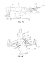
- FIG. 12 is a prospective view illustrating an example of a method of use, according to various embodiments.
- FIG. 13 is a side view illustrating an example of a method of use, according to various embodiments.
- FIG. 14 is a side view illustrating an example of a method of use, according to various embodiments.
- FIG. 15 is a side view illustrating an example of a method of use, according to various embodiments.
- FIG. 16 is a side view illustrating an example of a method of use, according to various embodiments.
- FIG. 17 is a side view illustrating an example of a method of use, according to various embodiments.
- FIG. 18 is a prospective view illustrating an example of a method of use, according to various embodiments.
- FIG. 19 is a prospective view illustrating a control handle, according to one embodiment.
- FIG. 20 is a top prospective view of an apparatus according to various embodiments.
- FIG. 21 is a flow chart illustrating a method of manufacturing an apparatus according to various embodiments.
- FIG. 22 is a prospective view illustrating an apparatus, in accordance various embodiments.
- the phrase “at least one of A, B, and C” should be construed to mean a logical (A or B or C), using a non-exclusive logical or.
- the phrase “A, B and/or C” should be construed to mean (A, B, and C) or alternatively (A or B or C), using a non-exclusive logical or. It should be understood that steps within a method may be executed in different order without altering the principles of the present disclosure.
- the terms “comprise”, “comprises”, “comprising”, “having”, “including”, “includes” or any variation thereof, are intended to reference a non-exclusive inclusion, such that a process, method, article, system, composition or apparatus that comprises a list of elements does not include only those elements recited, but may also include other elements not expressly listed or inherent to such process, method, article, system, composition or apparatus.
- Various embodiments may be described in terms of functional block components and various processing steps. For example, some embodiments may employ various user supports and mechanism enclosures, footholds, control handles, cable systems, and the like, which may be employed for variety of functions. In addition, some embodiments may be practiced in conjunction with any number of strength and conditioning equipment. Further, some embodiments may employ any number of conventional techniques for increasing flexibility, stretching muscles, and the like.
- apparatus, methods, and systems for increasing flexibility and/or stretching the muscles of a user generally comprise a user support set atop an enclosure.
- the enclosure houses mechanisms to actuate a cable system, wherein the mechanisms at least one of feed and retract a cable of the cable system.
- the apparatuses, methods, and systems also comprise footholds proximate to the user support to support at least the feet from a user, wherein the cable system actuates between the footholds, and wherein the footholds actuate in at least a lateral motion to further accentuate increasing flexibility and/or stretching the muscles.
- the apparatus, methods, and systems also comprise a control handle coupled to the cable system for the user to grasp, wherein the cable system actuates to either one of increase and release a tension to the grasped control handle, and wherein the control handle comprises at least one control to regulate the either one of increase and release the tension.
- Various embodiments may be applied to any apparatus for stretching muscles and/or increasing flexibility for a user.
- stretching muscles can increase flexibility of a user.
- the apparatus as described herein, may be used to at least one of stretch muscles and increase flexibility of a user.
- the stretching and/or the maneuvering of a joint such as for example, a knee, hips, discs of a spinal column, and combinations thereof, can increase the flexibility of a user.
- routines that repeatedly stretch muscles and/or joints can strengthen those muscles.
- muscle as used herein, can include tendons, ligaments, and other related connective tissue.
- joint can include cartilage, tendons, ligaments, connective tissue, and other related tissue. It is also understood that the term joint, as used herein, can include artificial implanted devices that replace or stabilize a damaged or worn joint, such as for example, a knee replacement, or a rebuilt hip.
- the apparatus can include a frame that is attached to a motor. One end of a cable can be attached to the motor. The cable wraps around a pulley that is attached to the frame. The cable attaches to a handle which can be integrated with the apparatus's controls. The user may grasp the handle during some stretching exercises.
- An attachment for stretching one's legs can also coupled to the frame and the motor. The user's foot may be placed on a foothold. There may be multiple footholds, accommodating the knee being straight or bent. The position of the foothold may also be adjusted, in order to accommodate users of varying heights.
- the attachment can be controlled and can be moved outward from the frame, inducing a stretch in the user's leg.
- the system controls can comprise electronics containing memory, which will enable the apparatus to run a predetermined program or to repeat the same stretches performed in a previous exercise session.
- the apparatus 100 may comprise a user support 110 to support the user 50 , footholds 120 , which may be proximate to the user support 110 to support feet from the user 50 , and a control handle 130 for the user 50 to grasp.
- the control handle 130 may be coupled to a cable system 140 , and in conjunction with the user support 110 and the footholds 120 , the cable system 140 may actuate to facilitate stretching at least one a muscle and a joint of the user 50 , which may increase flexibility.
- the user support 110 may set upon an enclosure 150 that may fully or partially house the cable system 140 , as well as house various hardware components, such as for example, a motor 160 .
- the enclosure 150 may further house various other components, such as for example, electronics 170 , drive systems, displays, computational devices, and the like.
- apparatus 100 can comprise platform, motor 160 coupled to the platform, seat mounted to the platform, rotating disk center-mounted to the platform, cable 140 coupled to motor 160 and interfaced with the rotating disk, handle 130 coupled to the cable and controller interfaced to motor 160 and configured to control at least one of cable 140 tension and motor 160 rotation.
- motor is configured to increase tension and release tension in the cable.
- apparatus 100 can further comprise leg component pivotally coupled to the platform and in communication with motor 160 .
- Leg component can comprise an adjustment mechanism configured to accommodate different sized bodies.
- leg component can comprise at least one foothold, which can include an adjustment mechanism configured to accommodate different sized bodies.
- Apparatus can comprise a memory system in communication with the controller.
- apparatus 100 can comprise platform, motor 160 coupled to the platform, seat mounted to the platform, rotating disk coupled to motor 160 , an arm interfaced with the rotating disk, handle 130 couple to the arm and controller interfaced to motor 160 and configured to control motor 160 rotation.
- the arm is can be configured to accommodate different sized bodies.
- the arm can comprise two members pivotally coupled.
- a user support 110 is illustrated to support the user 50 .
- the user support 110 may support the user 50 during use of the apparatus 100 .
- the user support 110 may comprise a bench that sets or is fastened atop the enclosure 150 .
- the user support 110 may comprise a seat having a back to also support the user 50 .
- the user support 110 may comprise an extension 1010 coupled to other parts of the enclosure 150 to support the knees or feet of the user 50 , such as illustrated in FIGS. 17 and 18 , or the user support 110 may comprise any other component now known or developed in the future that may support a user 50 .
- the user support 110 may be adjustable to accommodate variable sized users.
- the user support 110 may also comprise a lap belt to secure the position of the user 50 .
- the user support 110 may comprise various materials, padding, and the like to facilitate comfort and hygienic maintenance.
- the user support 110 and/or 1010 may actuate to alter the position of the user 50 .
- the user support 110 such as a seat having a back, may systematically, during operation of the apparatus, move in a back and forth motion, in an up and down motion, or a side to side motion, and/or any combination thereof.
- the apparatus 100 may comprise footholds 120 , wherein the footholds 120 may be configured to support feet from the user 50 .
- footholds are illustrated in use by the user 50 .
- the footholds 120 may be substantially proximate to the user support 110 and may be suitably coupled to one or a combination of the user support 110 , the enclosure 150 , and/or actuation mechanisms, such as the motor 160 , the cable system 140 , and the like.
- the footholds 120 may be adjustable to accommodate various positions of the user 50 during use of the apparatus 100 , as well as to accommodate the various sizes of various users.
- the footholds 120 may comprise not only elements to hold the user's feet, but may also comprise members that couple the footholds 120 to other above disclosed elements to assist in supporting any one or combination of the user's ankles, calves, thighs, etc.
- the footholds 120 may be variably positioned, for example the apparatus 100 may comprise upper footholds, such as footholds 120 , but the apparatus 100 may also comprise lower footholds, such as footholds 222 and representatively illustrated in use by the user 50 in FIGS. 13 and 16 .
- the foothold 120 may comprise a footplate 422 , which may be suitably coupled to a foothold member 120 .
- the foothold 120 may be adjustable.
- the foothold member 120 may adjust in a telescopic or any other extending/retracting manner, as illustrated by direction arrow 426 , to accommodate the preferences of the user 50 .
- the footplate 422 may be adjustable in a pivot wise manner, as illustrated by the direction arrow 428 , to also accommodate the preferences of a user 50 .
- the foothold plate 422 and/or the foothold member 120 may lock in position by clips, pins, hooks, snaps, and the like to secure their respective positions. In other embodiments, though, the foothold plate 422 and/or the foothold member 120 may be free to move during use of the apparatus 100 by the user 50 . While the foothold 120 may be used to support the feet of the user 50 , the foothold 120 may also fully and/or partially support the legs of the user 50 .
- the footholds 120 may be configured to facilitate supporting the legs and/or feet of the user 50 such that when the user 50 is seated upon the user support 110 the user 50 may comprise a seated straddled position. To facilitate this position, the footholds 120 may be configured to be substantially coplanar with the user support 110 . In other embodiments, however, the footholds 120 may be alternately positioned such that feet and/or legs of the user 50 may be positioned above and/or below the plane of the user support 110 .
- a front view of the apparatus 100 illustrates the footholds 120 in a standard substantially coplanar position 590 with the user support 110 , for example plane 501 .
- FIG. 5 a front view of the apparatus 100 illustrates the footholds 120 in a standard substantially coplanar position 590 with the user support 110 , for example plane 501 .
- FIG. 5 also illustrates the footholds 120 in alternate positions, position 592 and 594 ; wherein either one or both of the footholds 120 may be positioned below the plane 501 of the user support 110 , position 592 , and/or above the plane 501 of the user support 110 , position 594 .
- FIGS. 2 , 3 , and 6 still other positions of the footholds 120 may be incorporated by the user 50 as they use the apparatus 100 .
- FIGS illustrate the various lateral positions the footholds 120 may be positioned at during use.
- FIG. 2 illustrates the user 50 in a substantially straddled position, position 280 , wherein the users legs are spread wide apart, thereby fostering a first type of muscle stretching when using the apparatus 100 .
- FIG. 3 illustrates the user in an alternate position, position 385 , wherein the user's legs are positioned substantially closer together, thereby fostering a second type of muscle stretching.
- FIG. 6 a top down view of the footholds 120 of the apparatus 100 are illustrated among a range of various lateral positions.
- FIG. 6 illustrates the footholds 120 in a first position, position 696 , but either one or both of the footholds 120 may be positioned in other manners, such as a wider position, as illustrated by position 697 , and/or a narrower position, as illustrated by position 698 , as well as any other position in between, farther apart, or closer together.
- the various positions of the footholds 120 may be set and secured in a desired position prior to use, but in some embodiments, the footholds 120 may comprise actuation mechanisms such that the positions of the footholds 120 may change during use.
- any of the user 50 positions described herein may further apply to the various user positions, for example, but not limited to those illustrated in FIGS. 10A-18 .
- the apparatus 100 may comprise control handle 130 .
- Control handle 130 may be used to further facilitate increasing the flexibility and/or stretching the muscles of the user 50 .
- the control handle 130 may be coupled to a cable of the cable system 140 , wherein the cable system actuates to retract and/or feed the cable, thereby increasing and/or releasing the tension on the cable.
- the increasing tension facilitates pulling the user 50 holding the control handle 130 , and when the user 50 is positioned as illustrated and described above, such increasing tension facilitates the muscle stretching, thus increasing the flexibility of the user 50 .
- the decreasing tension allows the user 50 to return to their starting position.
- FIG. 2 the user 50 is illustrated in a substantially starting position, sitting upright with the cable extended.
- FIG. 3 illustrates the user 50 in a substantially final position, sitting bent over with the cable retracted.
- repeated motions between the starting position and final position can effectively stretch the muscles of the user 50 , thus increasing flexibility.
- the user 50 set upon the user support 110 may comprise the initial upright position 280 .
- the cable 745 of the cable system 140 may comprise a beginning extended length 748 .
- the user 50 may comprise a final bent over position 385 .
- the cable 745 may comprise a final retracted length 749 .
- the cable system 140 may release the tension on the cable 745 if and/or when the cable tension achieves a predetermined value. In this manner, the user 50 is safe from hyper extending themselves, thereby preventing injury, such as pulling and/or tearing their muscles.
- cable 745 can be replaced with a substantially straight rod which is coupled to extension arm 746 by a linkage.
- Motor 160 can move arm 746 at least one direction thus moving straight rod with handle attached.
- motor 160 can move arm 746 in a forward or a backward motion that is substantially parallel to support 110 .
- the user 50 may be stretched by holding handle 130 which is attached to straight rod that is pulled away from the user 50 by movement of arm 746 that is initiated and powered by motor 160 .
- control handle 130 may comprise controls 832 , cable 745 , control communication cable 834 , and/or hand grips 836 .
- Controls 832 may comprise various electronic switches, controls, settings, and the like to facilitate operation of the apparatus 100 .
- the controls may comprise simple on/off switches or may comprise variable resistance type switches to control, for example, variable value levels.
- the controls 832 may actuate the extension and/or retraction of the cable 745 .
- the controls may operate the cable system 140 as well as any foothold 120 movements and/or settings.
- the controls 832 may also control power, speed, timing, cable 745 tension levels, and the like.
- control handle 130 may comprise grips 836 for the user 50 to hold during use of the apparatus 100 .
- the control handle comprises a straight bar comprising textured areas 836 to facilitate a secure grip by the user 50 .
- the control handle 130 may comprise contoured portions to conform more readily to the user's grasp, or the control handle 130 may comprise other shape configurations, such as a T-bar, an H-bar, and the like.
- the apparatus 100 may comprise cable system 140 .
- the cable system 140 may suitably couple the control handle 130 to a drive mechanism, such as the motor 160 , which may operate to feed and/or retract the cable 745 thereby respectively increasing and/or releasing tension in the cable 745 , and thus facilitating the use of the apparatus 100 to increase flexibility and/or stretch the muscles of the user 50 .
- the cable system 140 may comprise the cable 745 that may be suitably coupled, via extension arm 746 , to an internal drive motor 160 .
- the cable system comprising the cable 745 may comprise a beginning extended length 748 .
- the user 50 may comprise a final bent over position 385 when the cable 745 comprises a final retracted length 749 .
- the user 50 may initiate the cable system 140 .
- the motor 160 may be actuated via the controls 832 to begin retracting the cable 745 , thereby increasing the tension on the cable 745 , and thus pulling the user 50 .
- the motor 160 may reverse direction to feed cable 745 , thereby decreasing the tension on the cable 745 , thus allowing the user 50 to return to the starting position 280 .
- the cable system 140 may not operate to feed or retract the cable 745 , but rather, as illustrated in FIG. 9 , the cable 745 may be fixed and the motor 160 may operate to raise and/or lower the extension arm 746 to facilitate moving the user from the starting position 280 to the final position 385 , direction arrow 907 . In still yet another embodiment, the cable system 140 may be configured to feed and/or retract the cable 745 as well as raise and/or lower the extension arm 746 .
- FIG. 10A illustrates a standard splits position
- FIG. 10B illustrates a splits forward position
- FIG. 11 illustrates a hip adductor stretch
- FIG. 12 illustrates a hip joint stretch
- FIG. 13 illustrates a hip external rotator and extensor stretch.
- FIG. 14 illustrates a seated knee flexor and hamstrings stretch
- FIG. 15 illustrates a raised-leg knee flexor and hamstrings stretch
- FIG. 16 illustrates a prone spine and shoulder stretch
- FIG. 17 illustrates a supine spine and shoulder stretch
- FIG. 18 illustrates an example of a splits stretch along with the various muscles that may be affected.
- the user 50 may operate the apparatus 100 comprising various reps, which may comprise various time intervals and/or in a graduated fashion (or other custom designed fashion) increase and/or decrease the tensions.
- the apparatus 100 may comprise various internal operating components, such as the motor 160 to facilitate the use of the apparatus 100 .
- the motor 160 may be suitably coupled to the cable 745 to retract and/or feed the cable 745 .
- the motor 160 may be suitably coupled to the extension arm 746 , and in still yet another embodiment the motor 160 may be suitably coupled to the footholds 120 , or perhaps suitably coupled to the user support 110 , such as a movable seat.
- the motor 160 may be suitably coupled to any one or any combination of these components as well as others now known or developed in the future.
- the motor 160 is merely one internal element configured to facilitate actuating the various components of the apparatus 100 , and other internal elements are contemplated by this disclosure.
- other internal components may comprise various combinations of drives, pulleys, gears, pistons, rods, shocks, sprockets, chains, belts, and the like, to facilitate operation of the apparatus 100 .
- the apparatus 100 may comprise various electronics 170 to further facilitate use of the apparatus 100 .
- the electronics 170 may be suitably coupled to various components to receive input, such as power from a power cord, communication from the control communication cable 834 , drive and/or operating information from the motor 160 , the cable 745 , the extension arm 746 , the footholds 120 , and the like.
- the electronics 170 may also be suitably coupled to various components to provide output, such as communication to the control communication cable 834 , drive and/or operating information to the motor 160 , the cable 745 , the extension arm 746 , the footholds 120 , and the like.
- the electronics 170 may also comprise various memory components, processors, drives, and the like.
- the apparatus 100 may comprise the enclosure 150 .
- the enclosure 150 may house various operating components of the apparatus 100 , such as the motor 160 , electronics 170 , as well all or a portion of the cable system 140 .
- the enclosure 150 may also provide a top surface to secure the user support 110 , such as a bench.
- the enclosure 150 may also comprise a structure to provide couplings for the footholds 120 , the extension arm 746 , etc.
- the enclosure 150 may be configured to house certain components, but other embodiments may comprise such components to be positioned outside of the enclosure 150 or completely apart from the enclosure 150 .
- components such as the motor 160 , the electronics 170 , portions of the cable system 140 , etc., may be positioned outside or completely apart from the enclosure 150 .
- the apparatus can include a frame that is attached to a motor. One end of a cable is attached to the motor. The cable wraps around a pulley that is attached to the frame. The cable attaches to a handle which is integrated with the apparatus's controls. The user grasps the handle during some stretching exercises.
- An attachment for stretching one's legs is also coupled to the frame and the motor. The user's foot is placed on a foothold. There may be multiple footholds, accommodating the knee being straight or bent. The position of the foothold may also be adjusted, in order to accommodate users of varying heights.
- the attachment is controlled and can be moved outward from the frame, inducing a stretch in the user's leg.
- the system controls will also consist of electronics containing memory, which will enable the apparatus to run a predetermined program or to repeat the same stretches done in a previous exercise session.
- Various embodiments provide a method comprising the steps of positioning a body on a platform, grasping handle 130 , activating a controller interfaced to motor 160 , controlling a tension of cable 140 coupled to motor 160 and handle 130 , and stretching at least one muscle in the body.
- the method can further comprise releasing the tension in cable 140 .
- the method can further comprise the steps of positioning a leg on a leg component, activating a controller interfaced to a motor 160 , and stretching at least one muscle in the leg.
- a method of stretching can include stretching muscles of at least one leg of the user 50 .
- the user 50 may be positioned on the user support 110 of the apparatus 100 , in a seated position faced toward the control handle 130 of the apparatus 100 .
- the feet of the user 50 can be positioned in footholds 120 , such that the position of the knees of the user 50 is substantially straight.
- the method can include positioning the control handle 130 in the hands of the user 50 and the user 50 grasping the control handle 130 .
- the method can comprise the user 50 activating the apparatus 100 by initiating the motor 160 by activating at least one component on the control handle 130 .
- the method can further comprise the user 50 controlling the rotation of the motor 160 by activating at least one component found on the control handle 130 .
- another person such as, for example, a trainer, a therapist, a health professional, or a caretaker may initiate and control the motor 160 by activating at least one component on the control handle 130 or a remote control.
- the method can further comprise the motor causing a tension in cable system 140 , such that the foothold member 120 may move pivotally away from the body of the apparatus 100 in the direction of arrow 108 , positioning the user 50 substantially in the position illustrated in FIG. 10A , where the legs of user 50 are substantially straight, are substantially positioned in the footholds 120 , and are spread away from each other. This position may be held for a period of time. After the period of time, the user 50 may release the tension in the cable system 160 by activating at least one component on the control handle 130 , thereby releasing the tension in the foothold members 120 .
- the tension may be released slowly, allowing the legs of the user 50 to return to an unstretched position and the foothold members 120 to move pivotally towards the structure of apparatus 100 in the direction of arrow 109 in a controlled and deliberate manner.
- another person may release the tension in the cable system 140 by activating at least one component on the control handle 130 or a remote controller.
- One embodiment can comprise a memory interfaced with the apparatus 100 that may record stretching sessions of the user 50 .
- the duration and distance of the stretch of the user 50 may be recorded by the memory.
- the method can comprise the routine that may be repeated or modified according to the desires of the user 50 during future sessions. For example, a user in physical therapy may need to progressively alter a stretching routine. In the initial stages of therapy, the patient may have very limited stretching mobility. Helping a patient regain flexibility may be part of the therapy. In such cases, it is very useful to have the patient's stretching history available so that the therapist may gage the patient's progress and help the patient achieve the desired flexibility.
- the therapist may use the memory in apparatus 100 to perform the most recent session's stretching routines and subsequently use, to stretch the patient further than before to aid the patient's recovery.
- the memory may be downloaded to a computer to chart progress or to provide reports, for example, the medical provider of the user 50 .
- the method of stretching muscles can include stretching at least one muscle of the user 50 .
- the method can comprise the user 50 starting in the position illustrated in FIG. 10A .
- This method can comprise the user 50 activating the motor 160 using the control handle 130 .
- the method further can comprise the user 50 controlling the rotation of the motor 160 by activating at least one component on the control handle 130 , such that a tension in the cable system 140 is created as the motor 160 rotates.
- another person may activate the motor 160 and control the motor rotation using the control handle 130 or a remote control.
- the tension in the cable system 140 increases, pulling the upper body of the user 50 forward in the direction of arrow 105 into a position similar to the position illustrated in FIG.
- This method can cause a stretch in at least one of the muscles of the user 50 .
- the method can include holding this position for a period of time. After the period of time, the user 50 may activate at least one component on the control handle 130 to release the tension in the cable system 140 . Alternatively, another person may activate at least one component on the control handle 130 or on a remote controller to release the tension in the cable system 140 .
- the user 50 to may return to the upright position illustrated in FIG. 10A as the tension in cable system 140 is released and as the user 50 move in the direction of arrow 106 .
- the method further can comprise the stretching routine being recorded in the memory interfaced with the apparatus 100 .
- the method can comprise recording at least one of the duration and distance of the stretches, as well as recording the time and date of the stretching routine.
- the method can comprise the same routine being repeated or modified according to the desires of the user 50 during future sessions, as described herein.
- the method can further comprise downloading the information to a computer for additional uses as described herein.
- the method can comprise the user 50 activating at least one component on the control handle 130 that activate the motor 160 and control the motor rotation.
- another person may activate the motor 160 and control the motor rotation using the control handle 130 or a remote control.
- the method can comprise the motor 160 rotating and creating a tension in the cable system 140 causing the user 50 to be pulled forward in the direction of arrow 105 , causing a stretch in the muscles of the user 50 .
- the method can comprise holding this position for a period of time. After the period of time, the user 50 may activate at least one component on the control handle 130 to release the tension in the cable system 140 . Alternatively, another person may release the tension in the cable system 140 by activating at least one component on the control handle 130 or on a remote controller.
- the user 50 may return to the upright position illustrated in FIG. 11 as the tension in cable system 140 is released and the user 50 moves in the direction of arrow 106 in a controlled and deliberate manner.
- the method further can comprise the stretching sequence being recorded in a memory interfaced with the apparatus 100 , such that the duration and distance of the stretch are recorded and are able to be repeated or modified according to the desires of the user 50 during a future stretching session, as described herein.
- the method can further comprise downloading the information to a computer for additional uses as described herein.
- a method of stretching can include stretching at least one muscle of user 50 .
- the user 50 may be positioned on the user support 110 of the apparatus 100 , such that the user 50 is seated facing toward the control handle 130 of the apparatus 100 .
- the feet of the user 50 may be positioned in footholds 222 , such that the knees of the user 50 are substantially bent and the user 50 is substantially straddling the apparatus 100 and the user support 110 .
- the method includes positioning the control handle 130 in the hands of the user 50 and the user 50 grasping the control handle 130 .
- the method can comprise the user 50 activating the motor 160 and controlling the motor rotation using the control handle 130 . Alternatively, another person may activate the motor 160 using the control handle 130 or a remote control.
- the method further can comprise the motor 160 rotating and causing a tension that moves the foothold members 120 pivotally away from the body of the apparatus 100 , substantially in the direction of arrow 108 , positioning the user 50 substantially in the position illustrated in FIG. 12 .
- This position may be held for a period of time.
- the user 50 may release the tension in the cable system 140 , releasing the tension in the foothold members 120 .
- another person may release the tension in the cable system 140 by activating at least one component on the control handle 130 or on a remote controller.
- the tension may be released slowly, allowing the foothold members 120 to move pivotally toward the structure of the apparatus 100 , substantially in the direction of arrow 109 , and the legs of the user 50 to return to an unstretched position in a controlled and deliberate manner.
- the method also can comprise the user 50 in the position illustrated in FIG. 12 and the motor 160 rotating such that there is a tension in the cable system 140 that cause the upper body of the user 50 to move substantially in the direction of the arrow 105 , causing a stretch in the muscles of the user 50 .
- the tension may be released as described herein, with the user 50 moving substantially in the direction of arrow 106 and returning to the position illustrated in FIG. 12 .
- the method further can comprise the stretching sequence being recorded in a memory interfaced with the apparatus 100 , such that the duration and distance of the stretch are recorded and are able to be repeated or modified according to the desires of the user 50 during a future stretching session, as described herein.
- the method can further comprise downloading the information to a computer for additional uses as described herein.
- This method can comprise positioning a user 50 on the user support 110 of the apparatus 100 such that the user 50 is seated facing the control handle 130 .
- the method can comprise positioning one of the feet of the user 50 in a foothold 120 of the apparatus 100 , such that the leg of the user 50 is substantially straight and positioning the other foot of the user 100 in a substantially flush position against the inner thigh of the first leg of user 50 .
- the user 50 may activate the motor 160 and control the motor rotation by activating at least one component on the control handle 130 .
- another person may activate the motor 160 and control the motor rotation using the control handle 130 or a remote controller.
- the method can comprise the motor 160 rotating, creating a tension in cable system 140 as the cable moves in the direction indicated by the arrow 105 , and causing the user 50 to move substantially in the direction of arrow 105 , causing a stretch in the muscles of the user 50 .
- the user 50 may release the tension in the cable system 140 by activating at least one component on the control handle 130 , allowing the user 50 to move in the direction of arrow 106 and return to the initial position illustrated in FIG. 13 in a deliberate and controlled manner as the tension in the cable system 140 is released.
- another person may release the tension in cable system 140 by activating at least one component on the control handle 130 or on a remote controller.
- the method further can comprise performing the stretching sequence with the left leg being straight and the right foot being against the left thigh (as illustrated in FIG. 13 ) and the right leg being straight and the left foot being against the right thigh (not illustrated).
- the method further can comprise the stretching sequence being recorded in a memory interfaced with the apparatus 100 , such that the duration and distance of the stretch are recorded and are able to be repeated or modified according to the desires of the user 50 during a future stretching session, as described herein.
- the method can further comprise downloading the information to a computer for additional uses as described herein.
- This method can comprise positioning a user 50 on the user support 110 of the apparatus 100 such that the user 50 is seated facing the control handle 130 .
- the method can comprise positioning both of the feet of the user 50 in the footholds 120 of the apparatus 100 .
- the method further can comprise positioning the control handle 130 in the hands of the user 50 .
- the user 50 may activate the motor 160 and control the motor rotation by activating at least one component on the control handle 130 .
- another person may activate the motor 160 by activating at least one component on the control handle 130 or on a remote control.
- the method can comprise the motor 160 rotating, creating a tension in cable system 140 , moving the user 50 substantially in the direction of the arrow 105 , and causing a stretch in the muscles of the user 50 .
- the user may release the tension in the cable system 140 , by activating at least one component on the controller handle 130 .
- another person may release the tension in the control handle 130 by activating at least one component on the control handle 130 or on a remote control.
- the method can comprise the user 50 moving in the direction of arrow 106 as the tension in cable system 140 is released and returning to the initial position illustrated in FIG. 14 in a deliberate and controlled manner.
- the method further can comprise the stretching sequence being recorded in a memory interfaced with the apparatus 100 , such that the duration and distance of the stretch are recorded and are able to be repeated or modified according to the desires of the user 50 during a future stretching session, as described herein.
- the method can further comprise downloading the information to a computer for additional uses as described herein.
- This method can comprise positioning a user 50 on the user support 110 of the apparatus 100 such that the user 50 faces the control handle 130 .
- the method can comprise positioning one of the feet of the user 50 in the foothold 120 of the apparatus 100 and positioning the other foot of the user 50 in the foothold 222 .
- the method further can comprise positioning the control handle 130 in the hands of the user 50 .
- the user 50 may activate the motor 160 and control the motor rotation by activating at least one component on the control handle 130 .
- another person may activate the motor 160 and control the motor rotation using the control handle 130 or a remote control.
- the method can comprise the motor 160 rotating, creating a tension in cable system 140 , pulling the upper body of the user 50 substantially in the direction of the arrow 105 , and causing a stretch in the muscles of the user 50 .
- the user 50 may release the tension in the cable system 140 , by activating at least one component on the controller handle 130 or on a remote control.
- another person may release the tension in the control handle 130 by activating at least one component on the control handle 130 or on a remote control.
- This method can comprise positioning the torso of a user 50 on the user support 110 of the apparatus 100 such that the user 50 is positioned chest-down on the user support 110 and such that the knees of the user 50 may be positioned on the user support 110 of the apparatus 100 .
- the method further can comprise positioning the control handle 130 in the hands of the user 50 .
- the user 50 may activate the motor 160 and control the motor rotation by activating at least one component on the control handle 130 .
- another person may activate the motor 160 and control the motor rotation using the control handle 130 or a remote control.
- the method can comprise the motor 160 rotating, creating a tension in cable system 140 , moving the user 50 substantially in the direction of the arrow 105 , and causing a stretch in the muscles of the user 50 .
- the user 50 may release the tension in the cable system 140 by activating at least one component on the controller handle 130 .
- another person may release the tension in the control handle 130 by activating at least one component on the control handle 130 or on a remote control.
- the method can comprise user 50 moving in the direction of arrow 106 as the tension in cable system 140 is released and returning to the initial position illustrated in FIG. 16 in a deliberate and controlled manner.
- the method further can comprise the stretching sequence being recorded in a memory interfaced with the apparatus 100 , such that the duration and distance of the stretch are recorded and are able to be repeated or modified according to the desires of the user 50 during a future stretching session, as described herein.
- the method can further comprise downloading the information to a computer for additional uses as described herein.
- This method can comprise positioning the torso of a user 50 on the user support 110 of the apparatus 100 such that the user 50 is positioned back-down on the user support 110 and such that the feet of the user 50 may be positioned on the user support 110 of the apparatus 100 .
- the method further can comprise positioning the control handle 130 in the hands of the user 50 .
- the user 50 may activate the motor 160 by activating at least one component on the control handle 130 .
- another person may activate the motor 160 using the control handle 130 or a remote control.
- the method can comprise the motor 160 rotating, creating a tension in cable system 140 , moving the user 50 substantially in the direction of the arrow 105 , inducing a stretch in the muscles of the user 50 .
- the user 50 may release the tension in the cable system 140 by activating at least one component on the controller handle 130 .
- another person may release the tension in the control handle 130 by activating at least one component on the control handle 130 or on a remote control.
- the method can comprise user 50 moving in the direction of arrow 106 as the tension in cable system 140 is released and returning to the initial position illustrated in FIG. 17 in a deliberate and controlled manner.
- the method further can comprise the stretching sequence being recorded in a memory interfaced with the apparatus 100 , such that the duration and distance of the stretch are recorded and are able to be repeated or modified according to the desires of the user 50 during a future stretching session, as described herein.
- the method can further comprise downloading the information to a computer for additional uses as described herein.
- the method can further comprise the motor causing a tension in cable system 140 , such that the foothold member 120 may move pivotally away from the body of the apparatus 100 in the direction of arrow 108 , positioning the user 50 substantially in the position illustrated in FIG. 18 , where the legs of user 50 are substantially straight, are substantially positioned in the footholds 120 , and are spread away from each other. This position may be held for a period of time. After the period of time, the user 50 may release the tension in the cable system 160 by activating at least one component on the control handle 130 , thereby releasing the tension in the foothold members 120 .
- the tension may be released slowly, allowing the legs of the user 50 to return to an unstretched position and the foothold members 120 to move pivotally towards the structure of apparatus 100 in the direction of arrow 109 in a controlled and deliberate manner.
- another person may release the tension in the cable system 140 by activating at least one component on the control handle 130 or a remote controller.
- One embodiment can comprise a memory interfaced with the apparatus 100 that may record stretching sessions of the user 50 .
- the duration and distance of the stretch of the user 50 may be recorded by the memory.
- the method can comprise the routine that may be repeated or modified according to the desires of the user 50 during future sessions. For example, a user in physical therapy may need to progressively alter a stretching routine. In the initial stages of therapy, the patient may have very limited stretching mobility. Helping a patient regain flexibility may be part of the therapy. In such cases, it is very useful to have the patient's stretching history available so that the therapist may gage the patient's progress and help the patient achieve the desired flexibility.
- the therapist may use the memory in apparatus 100 to perform the most recent session's stretching routines and subsequently use, to stretch the patient further than before to aid the patient's recovery.
- the memory may be downloaded to a computer to chart progress or to provide reports, for example, the medical provider of the user 50 .
- handle 130 comprises a pair of hand grips 836 and a center member 840 .
- the hand grips 836 are coupled to the center member, such that the center member 840 is substantially centered between the hand grips 836 .
- the center member 840 may also be coupled to a back plate 841 .
- the back plate 841 may comprise multiple openings that may be coupled to circuitry for controlling the motion of apparatus 100 .
- the circuitry may be coupled to the back plate 841 by any means.
- the circuitry may be coupled to the back plate 841 by the use of glue and/or one or more fasteners such as, for example, screws rivets, bolts, hook and loop, tongue and groove, or a collar.
- the circuitry may be coupled to the back plate 841 such that the circuitry passes through at least one opening in the back plate 841 .
- the circuitry may be connected wirelessly, thus eliminating such an opening.
- the back plate 841 may be fastened to the center member 840 by any means.
- the back plate 841 may be fastened by the use of screws, bolts, or rivets.
- the circuitry coupled to the back plate 841 may be contained within the center member 840 .
- a front plate 843 may be fastened to the center member 840 .
- Activation components 845 such as buttons, keys, or switches may be coupled to the front plate 843 by any means.
- the Activation components 845 may be coupled to the front plate 843 using fasteners.
- the circuitry may be coupled to the front plate 843 and to the Activation components 845 by any means.
- the circuitry may be coupled to the Activation components 845 by solder, and or by other means, such as, for example, glue or fasteners.
- the circuitry may be coupled to the front plate 843 by the use of glue and/or one or more fasteners such as, for example, screws rivets, bolts, hook and loop, tongue and groove, or a collar.
- the circuitry may be connected wirelessly, thus eliminating such connections. Further, the circuitry may be responsive to the Activation components 845 , such that the apparatus 100 may move to a determined position in response to activating at least one of the Activation components 845 .
- the circuitry may be interfaced with the motor 160 such that the user 50 may activate an Activation component 845 , which may cause a signal to be sent to the circuitry, which may cause the motor 160 to activate such that the various parts of the apparatus 100 , such as the leg supports, footholds, and handle 130 , may move.
- the circuitry may be arranged such that activating one Activation component 845 would activate only one part of the apparatus 100 , such as for example, moving a foothold pivotally outward from the apparatus 100 , for example as shown in FIG. 12 .
- the end of the circuitry opposite the end attached to the Activation components 845 may be coupled to the motor 160 by any means, such as, for example, using solder, glue, or a fastener adequate to join the circuitry to the motor 160 .
- the circuitry may be connected wirelessly, thus, eliminating such a connection to the motor.
- Various embodiments enable multiple methods of stretching.
- Various embodiments may comprise an apparatus 100 that may be positioned on a surfaced that is substantially flat, as illustrated in FIG. 20 .
- the apparatus 100 may be placed on the floor of a user's home, on the floor of a physical fitness center, or on the floor of a health care provider's facility.
- the apparatus 100 comprises a housing 150 and a motor 160 that is coupled to the housing 150 .
- a cable system 140 may be coupled to the housing 150 .
- the cable system 140 may comprise a cable 745 and a center mounted disk 747 , such as a pulley. One end of the cable 745 may be coupled to the motor 160 .
- the cable 745 may be coupled to the center mounted disk 747 , such that the cable 745 wraps around the center mounted disk 747 .
- the other end of the cable 745 may attach to a control handle 130 .
- Control handle 130 may comprise grips for both hands of user 50 and controls, such as switches, buttons, keys, knobs, levers, or other actuating devices for controlling the movement of apparatus 100 .
- a leg support 123 for stretching the legs of the user 50 may be coupled to the apparatus 100 .
- the leg support 123 may also be coupled to the motor 160 such that the leg support 123 may be controlled and may be moved pivotally outward from the housing 150 (as illustrated by arrow 109 ), causing a stretch in the muscles of the user 50 .
- the leg support 123 may be attached at one end to a mechanism that enables the leg support 123 to pivot outward from the body of the apparatus 100 .
- a roller 125 may be attached to the leg support 123 .
- the roller 125 may be in contact with the substantially flat surface. The roller 125 enables the leg support 123 to move pivotally outward from the housing 150 .
- At least one of the legs of the user 100 may be placed on at least one of the leg supports 123 .
- the leg support 123 may be adjustable in order to accommodate users of different heights.
- the apparatus 100 may comprise electronics which may comprise a memory.
- the memory may store a predetermined stretching routine.
- the memory may also store a stretching routine performed by the user 50 such that the user 50 or another may repeat a sequence of stretches done in a previous stretching session during a later session.
- the user 50 or another may adjust or modify the previous stretches to meet the needs of the user 50 , such as, for example, hold a stretch for a longer period of time, move the leg supports 123 pivotally outward further than in the previous session, or other adjustments according to the desires of the user 50 .
- the method 1100 may further comprise setting the user support atop an enclosure, wherein the enclosure houses mechanisms to actuate the cable system, and wherein the mechanisms may operate to at least one of feed and retract a cable of the cable system ( 1130 ).
- the method 1100 may further comprise coupling at least one of the mechanisms to the cable system such that the cable system releases the tension when the cable system achieves a pre-determined tension value ( 1140 ).
- various methods may also comprise packaging the apparatus and/or system, marketing the apparatus and/or system, drafting instructions to use and/or assemble the apparatus and/or system, and the like.
- the user support may be similar to user support 110 and/or 1010 ;
- the footholds may be similar to footholds 120 and/or 222 ,
- the control handle may be similar to control handle 130 ,
- the cable system may be similar to cable system 140 ,
- the cable may be similar to cable 745 ,
- the mechanisms may be similar to the motor 160 and/or the electronics 170 , and the enclosure may be similar to the enclosure 150 .
- Apparatus 100 can comprise motor 160 coupled to arm 746 which is connected to adjustable member 180 with a pivoting linkage 186 .
- adjustable member 180 couples handle 132 to pivoting linkage 186 .
- adjustable number 180 comprises an adjustment mechanism such as a screw linkage, holes and pins, compression adjustment, and the like. Adjustable member 180 can be varied in length to fit a variety of user sizes and weights.
- apparatus 100 and comprise motor 160 , which can be controlled but electronics 170 .
- motor 160 moves arm 746 in a forward and/or a backward motion which is substantially parallel to support 110 .
- controls 832 can be separate from handle 130 .
- controls 832 to can be a remote control unit which can be in communication with electronics 170 .
- motor 160 includes hydraulics in which to drive at least one of arm 746 and foothold members 222 .
- foothold members 222 move in substantially the same pivot motion as described here. Any of the exercises described in FIG. 10-18 can be performed using apparatus 100 as illustrated in FIG. 22 .
- first and second motors of motor 160 can be controlled by electronics 170 and programmed by controller 832 .
- motor 160 and/or electronics 170 is coupled to a power source such as a wall outlet.
- motor 160 and/or electronics 170 is powered by a rechargeable battery system.
- adjustable member 182 may cause adjustable member 182 and a direction perpendicular to support one time.
- adjustable member 180 moves perpendicular to support 110
- adjustable number 180 benefits on linkage 186 such that movement of arm 746 efficiently stretches user 50 of any size or weight.
- any method or process claims may be executed in any order and are not limited to the specific order presented in the claims.
- the components and/or elements recited in any apparatus or system claims may be assembled or otherwise operationally configured in a variety of permutations and are accordingly not limited to the specific configuration recited in the claims.
Landscapes
- Health & Medical Sciences (AREA)
- Life Sciences & Earth Sciences (AREA)
- Biophysics (AREA)
- Orthopedic Medicine & Surgery (AREA)
- General Health & Medical Sciences (AREA)
- Physical Education & Sports Medicine (AREA)
- Physics & Mathematics (AREA)
- Electromagnetism (AREA)
- Rehabilitation Tools (AREA)
- Orthopedics, Nursing, And Contraception (AREA)
Abstract
Description
- This application is a continuation in part of and claims priority to U.S. patent application Ser. No. 12/488,903, filed Jun. 22, 2009, which is incorporated by reference herein.
- This patent application generally relates to exercise equipment.
- Personal healthcare is a growing modern phenomenon as individuals become more and more health conscious. As part of a regular healthcare regiment, users incorporate various strength and conditioning programs. As part of such strength and conditioning programs, users often rely upon various exercise equipment. While much of this equipment is directed towards strength training, few are directed primarily with stretching and/or increasing a user's flexibility. It is well known that as a user's muscle develops, the muscles tend to lose a fair amount of flexibility. Also, a user undertaking a strength and conditioning regiment may be out of shape and lack adequately stretched muscles and/or have limited flexibility, which is a desired precursor to more advanced strength and conditioning.
- However, devices, which are directed towards increasing flexibility and/or stretching muscles, are active devices that the user to exert physical effort to push and pull themselves in conjunction with the various equipment.
- Various embodiments provide an apparatus configured to increase flexibility and/or stretch the muscles of a user generally includes, among other elements, (a) a user support to support the user; (b) an enclosure, wherein the enclosure houses mechanisms to actuate a cable system; (c) footholds proximate to the user support to support feet from the user; and (d) a control handle for the user to grasp, wherein the control handle is coupled to the cable system.
- The housed mechanisms operate to feed and retract a cable of the cable system, wherein the cable system may actuate between the footholds. In one embodiment, the footholds may actuate in a lateral direction to further accentuate increasing flexibility and/or stretching muscles. However, in other embodiments the footholds may actuate in a longitudinal direction, as well as in combinations of both lateral and longitudinal direction. The cable system operates to either one of increase and release a tension of the grasped control handle, and the control handle may comprise at least one control to regulate the either one of increase and release the tension.
- A passive device is disclosed that a user can operate to increase flexibility and/or stretch their muscles without exerting great physical effort, thereby obtaining a complete stretching before tiring from any pushing or pulling.
- The present disclosure will become more fully understood from the detailed description and the accompanying drawings, wherein:
-
FIG. 1 is a block diagram illustrating an apparatus, according to various embodiments; -
FIG. 2 is a prospective view illustrating a user in communication with an apparatus, according to various embodiments; -
FIG. 3 is a prospective view illustrating a user in communication with an apparatus, according to various embodiments; -
FIG. 4 is a diagrammatic side view of a portion of a foothold, according to various embodiments; -
FIG. 5 is a diagrammatic top view illustrating an apparatus having a plurality of foothold positions, according to various embodiments; -
FIG. 6 is a diagrammatic top view illustrating an apparatus having a plurality of foothold positions, according to various embodiments; -
FIG. 7 is a block diagram illustrating an apparatus, according to various embodiments; -
FIG. 8 is a prospective view illustrating a control handle, according to one embodiment; -
FIG. 9 is a block diagram illustrating an apparatus, according to various embodiments; -
FIGS. 10A and 10B are prospective views illustrating examples of methods, according to various embodiments; -
FIG. 11 is a prospective view illustrating an example of a method of use, according to various embodiments; -
FIG. 12 is a prospective view illustrating an example of a method of use, according to various embodiments; -
FIG. 13 is a side view illustrating an example of a method of use, according to various embodiments; -
FIG. 14 is a side view illustrating an example of a method of use, according to various embodiments; -
FIG. 15 is a side view illustrating an example of a method of use, according to various embodiments; -
FIG. 16 is a side view illustrating an example of a method of use, according to various embodiments; -
FIG. 17 is a side view illustrating an example of a method of use, according to various embodiments; -
FIG. 18 is a prospective view illustrating an example of a method of use, according to various embodiments; -
FIG. 19 is a prospective view illustrating a control handle, according to one embodiment; -
FIG. 20 is a top prospective view of an apparatus according to various embodiments; -
FIG. 21 is a flow chart illustrating a method of manufacturing an apparatus according to various embodiments; and -
FIG. 22 is a prospective view illustrating an apparatus, in accordance various embodiments - The following description is merely exemplary in nature and is in no way intended to limit the present disclosure, its application, or uses. For purposes of clarity, the same reference numbers will be used in the drawings to identify similar elements. As used herein, the phrase “at least one of A, B, and C” should be construed to mean a logical (A or B or C), using a non-exclusive logical or. As used herein, the phrase “A, B and/or C” should be construed to mean (A, B, and C) or alternatively (A or B or C), using a non-exclusive logical or. It should be understood that steps within a method may be executed in different order without altering the principles of the present disclosure. As used herein, the terms “comprise”, “comprises”, “comprising”, “having”, “including”, “includes” or any variation thereof, are intended to reference a non-exclusive inclusion, such that a process, method, article, system, composition or apparatus that comprises a list of elements does not include only those elements recited, but may also include other elements not expressly listed or inherent to such process, method, article, system, composition or apparatus.
- The drawings described herein are for illustration purposes only and are not intended to limit the scope of the present disclosure and the claims in any way. It is understood that the drawings are not drawn to scale and that like reference numbers refer to like elements throughout the drawings.
- Various embodiments may be described in terms of functional block components and various processing steps. For example, some embodiments may employ various user supports and mechanism enclosures, footholds, control handles, cable systems, and the like, which may be employed for variety of functions. In addition, some embodiments may be practiced in conjunction with any number of strength and conditioning equipment. Further, some embodiments may employ any number of conventional techniques for increasing flexibility, stretching muscles, and the like.
- In various embodiments, apparatus, methods, and systems for increasing flexibility and/or stretching the muscles of a user generally comprise a user support set atop an enclosure. The enclosure houses mechanisms to actuate a cable system, wherein the mechanisms at least one of feed and retract a cable of the cable system. The apparatuses, methods, and systems also comprise footholds proximate to the user support to support at least the feet from a user, wherein the cable system actuates between the footholds, and wherein the footholds actuate in at least a lateral motion to further accentuate increasing flexibility and/or stretching the muscles. The apparatus, methods, and systems also comprise a control handle coupled to the cable system for the user to grasp, wherein the cable system actuates to either one of increase and release a tension to the grasped control handle, and wherein the control handle comprises at least one control to regulate the either one of increase and release the tension.
- Various embodiments may be applied to any apparatus for stretching muscles and/or increasing flexibility for a user. As described herein, it is understood that stretching muscles can increase flexibility of a user. Accordingly, the apparatus, as described herein, may be used to at least one of stretch muscles and increase flexibility of a user. However, it is also understood that the stretching and/or the maneuvering of a joint, such as for example, a knee, hips, discs of a spinal column, and combinations thereof, can increase the flexibility of a user. It is also understood that routines that repeatedly stretch muscles and/or joints can strengthen those muscles. It is understood that the term muscle, as used herein, can include tendons, ligaments, and other related connective tissue. It is also understood that the term joint, as used herein, can include cartilage, tendons, ligaments, connective tissue, and other related tissue. It is also understood that the term joint, as used herein, can include artificial implanted devices that replace or stabilize a damaged or worn joint, such as for example, a knee replacement, or a rebuilt hip.
- Various embodiments of the apparatus enable multiple methods of stretching. The apparatus can include a frame that is attached to a motor. One end of a cable can be attached to the motor. The cable wraps around a pulley that is attached to the frame. The cable attaches to a handle which can be integrated with the apparatus's controls. The user may grasp the handle during some stretching exercises. An attachment for stretching one's legs can also coupled to the frame and the motor. The user's foot may be placed on a foothold. There may be multiple footholds, accommodating the knee being straight or bent. The position of the foothold may also be adjusted, in order to accommodate users of varying heights. The attachment can be controlled and can be moved outward from the frame, inducing a stretch in the user's leg. The system controls can comprise electronics containing memory, which will enable the apparatus to run a predetermined program or to repeat the same stretches performed in a previous exercise session.
- Referring now to
FIG. 1 , a block diagram illustrates one embodiment of anapparatus 100 to stretch the muscles of auser 50. In accordance with one embodiment, theapparatus 100 may comprise auser support 110 to support theuser 50,footholds 120, which may be proximate to theuser support 110 to support feet from theuser 50, and acontrol handle 130 for theuser 50 to grasp. The control handle 130 may be coupled to acable system 140, and in conjunction with theuser support 110 and thefootholds 120, thecable system 140 may actuate to facilitate stretching at least one a muscle and a joint of theuser 50, which may increase flexibility. In one embodiment, theuser support 110 may set upon anenclosure 150 that may fully or partially house thecable system 140, as well as house various hardware components, such as for example, amotor 160. Theenclosure 150 may further house various other components, such as for example,electronics 170, drive systems, displays, computational devices, and the like. - In various embodiments,
apparatus 100 can comprise platform,motor 160 coupled to the platform, seat mounted to the platform, rotating disk center-mounted to the platform,cable 140 coupled tomotor 160 and interfaced with the rotating disk, handle 130 coupled to the cable and controller interfaced tomotor 160 and configured to control at least one ofcable 140 tension andmotor 160 rotation. In one embodiment, motor is configured to increase tension and release tension in the cable. - In some embodiments,
apparatus 100 can further comprise leg component pivotally coupled to the platform and in communication withmotor 160. Leg component can comprise an adjustment mechanism configured to accommodate different sized bodies. Further, leg component can comprise at least one foothold, which can include an adjustment mechanism configured to accommodate different sized bodies. Apparatus can comprise a memory system in communication with the controller. - In various embodiments,
apparatus 100 can comprise platform,motor 160 coupled to the platform, seat mounted to the platform, rotating disk coupled tomotor 160, an arm interfaced with the rotating disk, handle 130 couple to the arm and controller interfaced tomotor 160 and configured to controlmotor 160 rotation. In one embodiment, the arm is can be configured to accommodate different sized bodies. In one embodiment, the arm can comprise two members pivotally coupled. - With reference to
FIGS. 2 and 3 , an example of auser support 110 is illustrated to support theuser 50. In one embodiment, theuser support 110 may support theuser 50 during use of theapparatus 100. In some embodiments, theuser support 110 may comprise a bench that sets or is fastened atop theenclosure 150. In some embodiments, theuser support 110 may comprise a seat having a back to also support theuser 50. In still another embodiment, theuser support 110 may comprise anextension 1010 coupled to other parts of theenclosure 150 to support the knees or feet of theuser 50, such as illustrated inFIGS. 17 and 18 , or theuser support 110 may comprise any other component now known or developed in the future that may support auser 50. Among the embodiments, theuser support 110 may be adjustable to accommodate variable sized users. Theuser support 110 may also comprise a lap belt to secure the position of theuser 50. Among various embodiments, theuser support 110 may comprise various materials, padding, and the like to facilitate comfort and hygienic maintenance. - In accordance with another embodiment, to further facilitate stretching a user's muscles and/or increase flexibility, the
user support 110 and/or 1010 may actuate to alter the position of theuser 50. For example, theuser support 110, such as a seat having a back, may systematically, during operation of the apparatus, move in a back and forth motion, in an up and down motion, or a side to side motion, and/or any combination thereof. - In accordance with various embodiments, the
apparatus 100 may comprisefootholds 120, wherein thefootholds 120 may be configured to support feet from theuser 50. Again with reference toFIGS. 2 and 3 , footholds are illustrated in use by theuser 50. Thefootholds 120 may be substantially proximate to theuser support 110 and may be suitably coupled to one or a combination of theuser support 110, theenclosure 150, and/or actuation mechanisms, such as themotor 160, thecable system 140, and the like. As illustrated byFIGS. 2 and 3 , thefootholds 120 may be adjustable to accommodate various positions of theuser 50 during use of theapparatus 100, as well as to accommodate the various sizes of various users. Thefootholds 120 may comprise not only elements to hold the user's feet, but may also comprise members that couple thefootholds 120 to other above disclosed elements to assist in supporting any one or combination of the user's ankles, calves, thighs, etc. In accordance with one embodiment, thefootholds 120 may be variably positioned, for example theapparatus 100 may comprise upper footholds, such asfootholds 120, but theapparatus 100 may also comprise lower footholds, such asfootholds 222 and representatively illustrated in use by theuser 50 inFIGS. 13 and 16 . - With reference to
FIG. 4 , a side view of afoothold 120 is illustrated. Thefoothold 120 may comprise afootplate 422, which may be suitably coupled to afoothold member 120. As illustrated inFIG. 4 , thefoothold 120 may be adjustable. For example, thefoothold member 120 may adjust in a telescopic or any other extending/retracting manner, as illustrated bydirection arrow 426, to accommodate the preferences of theuser 50. Moreover, thefootplate 422 may be adjustable in a pivot wise manner, as illustrated by thedirection arrow 428, to also accommodate the preferences of auser 50. In some embodiments thefoothold plate 422 and/or thefoothold member 120 may lock in position by clips, pins, hooks, snaps, and the like to secure their respective positions. In other embodiments, though, thefoothold plate 422 and/or thefoothold member 120 may be free to move during use of theapparatus 100 by theuser 50. While thefoothold 120 may be used to support the feet of theuser 50, thefoothold 120 may also fully and/or partially support the legs of theuser 50. - With reference to
FIGS. 2 and 3 , thefootholds 120 may be configured to facilitate supporting the legs and/or feet of theuser 50 such that when theuser 50 is seated upon theuser support 110 theuser 50 may comprise a seated straddled position. To facilitate this position, thefootholds 120 may be configured to be substantially coplanar with theuser support 110. In other embodiments, however, thefootholds 120 may be alternately positioned such that feet and/or legs of theuser 50 may be positioned above and/or below the plane of theuser support 110. For example, with reference toFIG. 5 , a front view of theapparatus 100 illustrates thefootholds 120 in a standard substantiallycoplanar position 590 with theuser support 110, forexample plane 501.FIG. 5 also illustrates thefootholds 120 in alternate positions,position footholds 120 may be positioned below theplane 501 of theuser support 110,position 592, and/or above theplane 501 of theuser support 110,position 594. - With reference to
FIGS. 2 , 3, and 6, still other positions of thefootholds 120 may be incorporated by theuser 50 as they use theapparatus 100. These FIGS illustrate the various lateral positions thefootholds 120 may be positioned at during use. For example,FIG. 2 illustrates theuser 50 in a substantially straddled position,position 280, wherein the users legs are spread wide apart, thereby fostering a first type of muscle stretching when using theapparatus 100.FIG. 3 , illustrates the user in an alternate position,position 385, wherein the user's legs are positioned substantially closer together, thereby fostering a second type of muscle stretching. - In one embodiment and with reference to
FIG. 6 , a top down view of thefootholds 120 of theapparatus 100 are illustrated among a range of various lateral positions. For example,FIG. 6 illustrates thefootholds 120 in a first position,position 696, but either one or both of thefootholds 120 may be positioned in other manners, such as a wider position, as illustrated byposition 697, and/or a narrower position, as illustrated byposition 698, as well as any other position in between, farther apart, or closer together. - It should be noted that during use of the
apparatus 100 by theuser 50, the various positions of thefootholds 120 may be set and secured in a desired position prior to use, but in some embodiments, thefootholds 120 may comprise actuation mechanisms such that the positions of thefootholds 120 may change during use. - It should further be noted that the various positions and/or configurations of the
footholds 120 described above may also apply to thelower footholds 222. Moreover, any of theuser 50 positions described herein, may further apply to the various user positions, for example, but not limited to those illustrated inFIGS. 10A-18 . - In accordance with one embodiment, the
apparatus 100 may comprisecontrol handle 130. Control handle 130 may be used to further facilitate increasing the flexibility and/or stretching the muscles of theuser 50. In one embodiment, the control handle 130 may be coupled to a cable of thecable system 140, wherein the cable system actuates to retract and/or feed the cable, thereby increasing and/or releasing the tension on the cable. In this manner, the increasing tension facilitates pulling theuser 50 holding the control handle 130, and when theuser 50 is positioned as illustrated and described above, such increasing tension facilitates the muscle stretching, thus increasing the flexibility of theuser 50. The decreasing tension allows theuser 50 to return to their starting position. - For example, with reference to
FIG. 2 theuser 50 is illustrated in a substantially starting position, sitting upright with the cable extended.FIG. 3 illustrates theuser 50 in a substantially final position, sitting bent over with the cable retracted. As can be seen from these FIGS, repeated motions between the starting position and final position can effectively stretch the muscles of theuser 50, thus increasing flexibility. - As a further example and with reference to
FIG. 7 , a schematic of the movement between the starting and final position is illustrated. Theuser 50 set upon theuser support 110 may comprise the initialupright position 280. In this position thecable 745 of thecable system 140 may comprise a beginning extendedlength 748. In the final position,position 385, theuser 50 may comprise a final bent overposition 385. In this position thecable 745, may comprise a final retractedlength 749. By holding onto the control handle 130, the user is pulled fromposition 280 toposition 385, thereby decreasing the angle between the user, i.e. the user's torso, and theuser support 110; illustrated byangle arrows user 50, thecable system 140 may release the tension on thecable 745 if and/or when the cable tension achieves a predetermined value. In this manner, theuser 50 is safe from hyper extending themselves, thereby preventing injury, such as pulling and/or tearing their muscles. - In one embodiment,
cable 745 can be replaced with a substantially straight rod which is coupled toextension arm 746 by a linkage.Motor 160 can movearm 746 at least one direction thus moving straight rod with handle attached. In some embodiments,motor 160 can movearm 746 in a forward or a backward motion that is substantially parallel to support 110. Theuser 50 may be stretched by holdinghandle 130 which is attached to straight rod that is pulled away from theuser 50 by movement ofarm 746 that is initiated and powered bymotor 160. - With reference to
FIG. 8 , a close up of control handle 130 is illustrated. In one embodiment, control handle 130 may comprisecontrols 832,cable 745,control communication cable 834, and/or hand grips 836.Controls 832 may comprise various electronic switches, controls, settings, and the like to facilitate operation of theapparatus 100. The controls may comprise simple on/off switches or may comprise variable resistance type switches to control, for example, variable value levels. For example, thecontrols 832 may actuate the extension and/or retraction of thecable 745. The controls may operate thecable system 140 as well as anyfoothold 120 movements and/or settings. Thecontrols 832 may also control power, speed, timing,cable 745 tension levels, and the like. In some embodiments, thecontrols 832 may further comprise visual displays and/or other outputs, such as audio and touch sensory feedback mechanisms. Among the various embodiments, thecontrols 832 may communicate withother apparatus 100 components via thecontrol communication cable 834, but in some embodiments, the communication may be conducted wirelessly using infrared and/or radio receiving/transmission elements. In still other embodiments thecontrol communication cable 834 and/or any wireless embodiments may communicate with not only other components of theapparatus 100, but may also be configured to communicate with other devices, such as a PC, a cell phone, a PDA, and the like so as to convey usage information. Such usage information may be useful to track a user's progress, to monitor maintenance schedules, and the like. In still yet other embodiments, in addition tocontrol communication cable 834 and/or any other wireless embodiments, the control handle 130 may comprise internal memory capabilities, removable memory capabilities, and the like to further store and/or provide information. - In accordance with various embodiments, the control handle 130 may comprise
grips 836 for theuser 50 to hold during use of theapparatus 100. In the example illustrated inFIG. 8 , the control handle comprises a straight bar comprisingtextured areas 836 to facilitate a secure grip by theuser 50. It should be understood, however, that any type of control handle configuration may be used without departing from the scope of the various embodiments described herein. For example, the control handle 130 may comprise contoured portions to conform more readily to the user's grasp, or the control handle 130 may comprise other shape configurations, such as a T-bar, an H-bar, and the like. - In accordance with various embodiments, the
apparatus 100 may comprisecable system 140. Thecable system 140 may suitably couple the control handle 130 to a drive mechanism, such as themotor 160, which may operate to feed and/or retract thecable 745 thereby respectively increasing and/or releasing tension in thecable 745, and thus facilitating the use of theapparatus 100 to increase flexibility and/or stretch the muscles of theuser 50. With return reference toFIG. 7 , thecable system 140 may comprise thecable 745 that may be suitably coupled, viaextension arm 746, to aninternal drive motor 160. As briefly described above, when theuser 50 is in the beginningupright position 280, the cable system comprising thecable 745 may comprise a beginning extendedlength 748. In the final position,position 385, theuser 50 may comprise a final bent overposition 385 when thecable 745 comprises a final retractedlength 749. - In accordance with various embodiments, using the
controls 832 on the control handle 130, theuser 50 may initiate thecable system 140. For example, themotor 160 may be actuated via thecontrols 832 to begin retracting thecable 745, thereby increasing the tension on thecable 745, and thus pulling theuser 50. Once theuser 50 reaches thefinal position 385, themotor 160 may reverse direction to feedcable 745, thereby decreasing the tension on thecable 745, thus allowing theuser 50 to return to the startingposition 280. - In accordance with various embodiments, the
cable system 140 may not operate to feed or retract thecable 745, but rather, as illustrated inFIG. 9 , thecable 745 may be fixed and themotor 160 may operate to raise and/or lower theextension arm 746 to facilitate moving the user from the startingposition 280 to thefinal position 385,direction arrow 907. In still yet another embodiment, thecable system 140 may be configured to feed and/or retract thecable 745 as well as raise and/or lower theextension arm 746. It should be noted that the retraction and feeding of thecable 745, and the raising and/or lowering of theextension arm 746 are merely two examples of components that facilitate any “pulling” and/or “releasing” of theuser 50 to effectuate increasing flexibility and/or stretching their muscles. It should be appreciated that any other like components that facilitate such movement of theuser 50 are contemplated by this disclosure, for example, rods, pistons, pulleys, gears, fly wheels, levers, screws, etc. - In accordance with various embodiments, and as mentioned briefly earlier, the
user 50 may employ many variable positions to realize the benefits of theapparatus 100, andFIGS. 10A-18 representatively illustrate many, but certainly not all of the possible positions. For example,FIG. 10A illustrates a standard splits position,FIG. 10B illustrates a splits forward position,FIG. 11 illustrates a hip adductor stretch,FIG. 12 illustrates a hip joint stretch, andFIG. 13 illustrates a hip external rotator and extensor stretch. In other examples,FIG. 14 illustrates a seated knee flexor and hamstrings stretch,FIG. 15 illustrates a raised-leg knee flexor and hamstrings stretch,FIG. 16 illustrates a prone spine and shoulder stretch, andFIG. 17 illustrates a supine spine and shoulder stretch.FIG. 18 illustrates an example of a splits stretch along with the various muscles that may be affected. - In accordance with the variable positions, the
user 50 may operate theapparatus 100 comprising various reps, which may comprise various time intervals and/or in a graduated fashion (or other custom designed fashion) increase and/or decrease the tensions. - In accordance with various embodiments, the
apparatus 100 may comprise various internal operating components, such as themotor 160 to facilitate the use of theapparatus 100. For example, themotor 160 may be suitably coupled to thecable 745 to retract and/or feed thecable 745. In another embodiment, themotor 160 may be suitably coupled to theextension arm 746, and in still yet another embodiment themotor 160 may be suitably coupled to thefootholds 120, or perhaps suitably coupled to theuser support 110, such as a movable seat. Themotor 160 may be suitably coupled to any one or any combination of these components as well as others now known or developed in the future. - It should further be noted that the
motor 160 is merely one internal element configured to facilitate actuating the various components of theapparatus 100, and other internal elements are contemplated by this disclosure. For example, other internal components may comprise various combinations of drives, pulleys, gears, pistons, rods, shocks, sprockets, chains, belts, and the like, to facilitate operation of theapparatus 100. - In accordance with various embodiments, the
apparatus 100 may comprisevarious electronics 170 to further facilitate use of theapparatus 100. As briefly described throughout, theelectronics 170 may be suitably coupled to various components to receive input, such as power from a power cord, communication from thecontrol communication cable 834, drive and/or operating information from themotor 160, thecable 745, theextension arm 746, thefootholds 120, and the like. Theelectronics 170 may also be suitably coupled to various components to provide output, such as communication to thecontrol communication cable 834, drive and/or operating information to themotor 160, thecable 745, theextension arm 746, thefootholds 120, and the like. Among the various embodiments, theelectronics 170 may also comprise various memory components, processors, drives, and the like. - In accordance with one embodiment, the
apparatus 100 may comprise theenclosure 150. Theenclosure 150 may house various operating components of theapparatus 100, such as themotor 160,electronics 170, as well all or a portion of thecable system 140. Theenclosure 150 may also provide a top surface to secure theuser support 110, such as a bench. Theenclosure 150 may also comprise a structure to provide couplings for thefootholds 120, theextension arm 746, etc. It should be noted that among the various embodiments, theenclosure 150 may be configured to house certain components, but other embodiments may comprise such components to be positioned outside of theenclosure 150 or completely apart from theenclosure 150. For example, components such as themotor 160, theelectronics 170, portions of thecable system 140, etc., may be positioned outside or completely apart from theenclosure 150. - Various embodiments of the apparatus enable multiple methods of stretching. The apparatus can include a frame that is attached to a motor. One end of a cable is attached to the motor. The cable wraps around a pulley that is attached to the frame. The cable attaches to a handle which is integrated with the apparatus's controls. The user grasps the handle during some stretching exercises. An attachment for stretching one's legs is also coupled to the frame and the motor. The user's foot is placed on a foothold. There may be multiple footholds, accommodating the knee being straight or bent. The position of the foothold may also be adjusted, in order to accommodate users of varying heights. The attachment is controlled and can be moved outward from the frame, inducing a stretch in the user's leg. The system controls will also consist of electronics containing memory, which will enable the apparatus to run a predetermined program or to repeat the same stretches done in a previous exercise session.
- Various embodiments provide a method comprising the steps of positioning a body on a platform, grasping
handle 130, activating a controller interfaced tomotor 160, controlling a tension ofcable 140 coupled tomotor 160 and handle 130, and stretching at least one muscle in the body. The method can further comprise releasing the tension incable 140. The method can further comprise the steps of positioning a leg on a leg component, activating a controller interfaced to amotor 160, and stretching at least one muscle in the leg. - Various embodiments provide a method comprising the steps of
rotating cable 140 coupled tomotor 160 on one end ofcable 140 and to a body interface to create resistance on a body part coupled to the body interface, andmotor 160 controls the resistance on the body part. Thecable 140 rotation can be controlled bymotor 160. Thecable 140 can be attached to handle 130. Thecable 140 can attach to a leg component. - As illustrated in
FIG. 10A , a method of stretching can include stretching muscles of at least one leg of theuser 50. According to the method, theuser 50 may be positioned on theuser support 110 of theapparatus 100, in a seated position faced toward the control handle 130 of theapparatus 100. The feet of theuser 50 can be positioned infootholds 120, such that the position of the knees of theuser 50 is substantially straight. The method can include positioning the control handle 130 in the hands of theuser 50 and theuser 50 grasping thecontrol handle 130. The method can comprise theuser 50 activating theapparatus 100 by initiating themotor 160 by activating at least one component on thecontrol handle 130. The method can further comprise theuser 50 controlling the rotation of themotor 160 by activating at least one component found on thecontrol handle 130. Alternatively, another person, such as, for example, a trainer, a therapist, a health professional, or a caretaker may initiate and control themotor 160 by activating at least one component on the control handle 130 or a remote control. - The method can further comprise the motor causing a tension in
cable system 140, such that thefoothold member 120 may move pivotally away from the body of theapparatus 100 in the direction ofarrow 108, positioning theuser 50 substantially in the position illustrated inFIG. 10A , where the legs ofuser 50 are substantially straight, are substantially positioned in thefootholds 120, and are spread away from each other. This position may be held for a period of time. After the period of time, theuser 50 may release the tension in thecable system 160 by activating at least one component on the control handle 130, thereby releasing the tension in thefoothold members 120. According to one embodiment, the tension may be released slowly, allowing the legs of theuser 50 to return to an unstretched position and thefoothold members 120 to move pivotally towards the structure ofapparatus 100 in the direction ofarrow 109 in a controlled and deliberate manner. Alternatively, another person may release the tension in thecable system 140 by activating at least one component on the control handle 130 or a remote controller. - One embodiment can comprise a memory interfaced with the
apparatus 100 that may record stretching sessions of theuser 50. The duration and distance of the stretch of theuser 50 may be recorded by the memory. The method can comprise the routine that may be repeated or modified according to the desires of theuser 50 during future sessions. For example, a user in physical therapy may need to progressively alter a stretching routine. In the initial stages of therapy, the patient may have very limited stretching mobility. Helping a patient regain flexibility may be part of the therapy. In such cases, it is very useful to have the patient's stretching history available so that the therapist may gage the patient's progress and help the patient achieve the desired flexibility. During therapy sessions, the therapist may use the memory inapparatus 100 to perform the most recent session's stretching routines and subsequently use, to stretch the patient further than before to aid the patient's recovery. The memory may be downloaded to a computer to chart progress or to provide reports, for example, the medical provider of theuser 50. - As illustrated in
FIG. 10B , the method of stretching muscles can include stretching at least one muscle of theuser 50. The method can comprise theuser 50 starting in the position illustrated inFIG. 10A . This method can comprise theuser 50 activating themotor 160 using thecontrol handle 130. The method further can comprise theuser 50 controlling the rotation of themotor 160 by activating at least one component on the control handle 130, such that a tension in thecable system 140 is created as themotor 160 rotates. Alternatively, another person may activate themotor 160 and control the motor rotation using the control handle 130 or a remote control. Asmotor 160 rotates, the tension in thecable system 140 increases, pulling the upper body of theuser 50 forward in the direction ofarrow 105 into a position similar to the position illustrated inFIG. 10B where the legs ofuser 50 are spread as illustrated inFIG. 10A and the torso ofuser 50 is bent forward, toward theuser support 110. This method can cause a stretch in at least one of the muscles of theuser 50. The method can include holding this position for a period of time. After the period of time, theuser 50 may activate at least one component on the control handle 130 to release the tension in thecable system 140. Alternatively, another person may activate at least one component on the control handle 130 or on a remote controller to release the tension in thecable system 140. - According to the method, the
user 50 to may return to the upright position illustrated inFIG. 10A as the tension incable system 140 is released and as theuser 50 move in the direction ofarrow 106. The method further can comprise the stretching routine being recorded in the memory interfaced with theapparatus 100. The method can comprise recording at least one of the duration and distance of the stretches, as well as recording the time and date of the stretching routine. The method can comprise the same routine being repeated or modified according to the desires of theuser 50 during future sessions, as described herein. The method can further comprise downloading the information to a computer for additional uses as described herein. - As illustrated in
FIG. 11 a method of stretching can include stretching at least one muscle in the body of theuser 50. The method consists of placing theuser 50 on theuser support 110 of theapparatus 100. Theuser 50 is positioned on theapparatus 100 such that theuser 50 is seated facing thecontrol handle 130. The method also can comprise positioning the feet of theuser 50 on theuser support 110 such that the feet are substantially close to the body and are substantially resting on their sides, and the knees of theuser 50 are substantially spread away from the body. This may be referred to as a butterfly position. The method further can comprise positioning the control handle 130 in the hands of theuser 50, such that theuser 50 may grasp thecontrol handle 130. The method can comprise theuser 50 activating at least one component on the control handle 130 that activate themotor 160 and control the motor rotation. Alternatively, another person may activate themotor 160 and control the motor rotation using the control handle 130 or a remote control. The method can comprise themotor 160 rotating and creating a tension in thecable system 140 causing theuser 50 to be pulled forward in the direction ofarrow 105, causing a stretch in the muscles of theuser 50. The method can comprise holding this position for a period of time. After the period of time, theuser 50 may activate at least one component on the control handle 130 to release the tension in thecable system 140. Alternatively, another person may release the tension in thecable system 140 by activating at least one component on the control handle 130 or on a remote controller. - According to the method, the
user 50 may return to the upright position illustrated inFIG. 11 as the tension incable system 140 is released and theuser 50 moves in the direction ofarrow 106 in a controlled and deliberate manner. The method further can comprise the stretching sequence being recorded in a memory interfaced with theapparatus 100, such that the duration and distance of the stretch are recorded and are able to be repeated or modified according to the desires of theuser 50 during a future stretching session, as described herein. The method can further comprise downloading the information to a computer for additional uses as described herein. - As illustrated in
FIG. 12 a method of stretching can include stretching at least one muscle ofuser 50. According to the method, theuser 50 may be positioned on theuser support 110 of theapparatus 100, such that theuser 50 is seated facing toward the control handle 130 of theapparatus 100. The feet of theuser 50 may be positioned infootholds 222, such that the knees of theuser 50 are substantially bent and theuser 50 is substantially straddling theapparatus 100 and theuser support 110. The method includes positioning the control handle 130 in the hands of theuser 50 and theuser 50 grasping thecontrol handle 130. The method can comprise theuser 50 activating themotor 160 and controlling the motor rotation using thecontrol handle 130. Alternatively, another person may activate themotor 160 using the control handle 130 or a remote control. The method further can comprise themotor 160 rotating and causing a tension that moves thefoothold members 120 pivotally away from the body of theapparatus 100, substantially in the direction ofarrow 108, positioning theuser 50 substantially in the position illustrated inFIG. 12 . This position may be held for a period of time. After the period of time, theuser 50 may release the tension in thecable system 140, releasing the tension in thefoothold members 120. Alternatively, another person may release the tension in thecable system 140 by activating at least one component on the control handle 130 or on a remote controller. - According to one embodiment, the tension may be released slowly, allowing the
foothold members 120 to move pivotally toward the structure of theapparatus 100, substantially in the direction ofarrow 109, and the legs of theuser 50 to return to an unstretched position in a controlled and deliberate manner. The method also can comprise theuser 50 in the position illustrated inFIG. 12 and themotor 160 rotating such that there is a tension in thecable system 140 that cause the upper body of theuser 50 to move substantially in the direction of thearrow 105, causing a stretch in the muscles of theuser 50. The tension may be released as described herein, with theuser 50 moving substantially in the direction ofarrow 106 and returning to the position illustrated inFIG. 12 . The method further can comprise the stretching sequence being recorded in a memory interfaced with theapparatus 100, such that the duration and distance of the stretch are recorded and are able to be repeated or modified according to the desires of theuser 50 during a future stretching session, as described herein. The method can further comprise downloading the information to a computer for additional uses as described herein. - With reference to
FIG. 13 , a method of stretching according to various embodiments is illustrated. This method can comprise positioning auser 50 on theuser support 110 of theapparatus 100 such that theuser 50 is seated facing thecontrol handle 130. The method can comprise positioning one of the feet of theuser 50 in afoothold 120 of theapparatus 100, such that the leg of theuser 50 is substantially straight and positioning the other foot of theuser 100 in a substantially flush position against the inner thigh of the first leg ofuser 50. Theuser 50 may activate themotor 160 and control the motor rotation by activating at least one component on thecontrol handle 130. Alternatively, another person may activate themotor 160 and control the motor rotation using the control handle 130 or a remote controller. - The method can comprise the
motor 160 rotating, creating a tension incable system 140 as the cable moves in the direction indicated by thearrow 105, and causing theuser 50 to move substantially in the direction ofarrow 105, causing a stretch in the muscles of theuser 50. After holding the stretch for a period of time theuser 50 may release the tension in thecable system 140 by activating at least one component on the control handle 130, allowing theuser 50 to move in the direction ofarrow 106 and return to the initial position illustrated inFIG. 13 in a deliberate and controlled manner as the tension in thecable system 140 is released. Alternatively, another person may release the tension incable system 140 by activating at least one component on the control handle 130 or on a remote controller. The method further can comprise performing the stretching sequence with the left leg being straight and the right foot being against the left thigh (as illustrated inFIG. 13 ) and the right leg being straight and the left foot being against the right thigh (not illustrated). The method further can comprise the stretching sequence being recorded in a memory interfaced with theapparatus 100, such that the duration and distance of the stretch are recorded and are able to be repeated or modified according to the desires of theuser 50 during a future stretching session, as described herein. The method can further comprise downloading the information to a computer for additional uses as described herein. - With reference to
FIG. 14 a method of stretching according to various embodiments is illustrated. This method can comprise positioning auser 50 on theuser support 110 of theapparatus 100 such that theuser 50 is seated facing thecontrol handle 130. The method can comprise positioning both of the feet of theuser 50 in thefootholds 120 of theapparatus 100. The method further can comprise positioning the control handle 130 in the hands of theuser 50. Theuser 50 may activate themotor 160 and control the motor rotation by activating at least one component on thecontrol handle 130. Alternatively, another person may activate themotor 160 by activating at least one component on the control handle 130 or on a remote control. - The method can comprise the
motor 160 rotating, creating a tension incable system 140, moving theuser 50 substantially in the direction of thearrow 105, and causing a stretch in the muscles of theuser 50. After holding the stretch for a period of time the user may release the tension in thecable system 140, by activating at least one component on thecontroller handle 130. Alternatively, another person may release the tension in the control handle 130 by activating at least one component on the control handle 130 or on a remote control. The method can comprise theuser 50 moving in the direction ofarrow 106 as the tension incable system 140 is released and returning to the initial position illustrated inFIG. 14 in a deliberate and controlled manner. The method further can comprise the stretching sequence being recorded in a memory interfaced with theapparatus 100, such that the duration and distance of the stretch are recorded and are able to be repeated or modified according to the desires of theuser 50 during a future stretching session, as described herein. The method can further comprise downloading the information to a computer for additional uses as described herein. - With reference to
FIG. 15 a method of stretching according to various embodiments is illustrated. This method can comprise positioning auser 50 on theuser support 110 of theapparatus 100 such that theuser 50 faces thecontrol handle 130. The method can comprise positioning one of the feet of theuser 50 in thefoothold 120 of theapparatus 100 and positioning the other foot of theuser 50 in thefoothold 222. The method further can comprise positioning the control handle 130 in the hands of theuser 50. Theuser 50 may activate themotor 160 and control the motor rotation by activating at least one component on thecontrol handle 130. Alternatively, another person may activate themotor 160 and control the motor rotation using the control handle 130 or a remote control. The method can comprise themotor 160 rotating, creating a tension incable system 140, pulling the upper body of theuser 50 substantially in the direction of thearrow 105, and causing a stretch in the muscles of theuser 50. After holding the stretch for a period of time theuser 50 may release the tension in thecable system 140, by activating at least one component on the controller handle 130 or on a remote control. Alternatively, another person may release the tension in the control handle 130 by activating at least one component on the control handle 130 or on a remote control. - The method can comprise the
user 50 moving in the direction ofarrow 106 as the tension incable system 140 is released and returning to the initial position illustrated inFIG. 15 in a deliberate and controlled manner. The method also can comprise the left foot of theuser 50 being positioned infoothold 120 and the right foot being positioned in foothold 222 (as illustrated inFIG. 15 ) and the left foot being positioned infoothold 222 and the right foot being positioned in foothold 120 (not illustrated). The method further can comprise the stretching sequence being recorded in a memory interfaced with theapparatus 100, such that the duration and distance of the stretch are recorded and are able to be repeated or modified according to the desires of theuser 50 during a future stretching session, as described herein. The method can further comprise downloading the information to a computer for additional uses as described herein. - With reference to
FIG. 16 a method of stretching according to various embodiments is illustrated. This method can comprise positioning the torso of auser 50 on theuser support 110 of theapparatus 100 such that theuser 50 is positioned chest-down on theuser support 110 and such that the knees of theuser 50 may be positioned on theuser support 110 of theapparatus 100. The method further can comprise positioning the control handle 130 in the hands of theuser 50. Theuser 50 may activate themotor 160 and control the motor rotation by activating at least one component on thecontrol handle 130. Alternatively, another person may activate themotor 160 and control the motor rotation using the control handle 130 or a remote control. The method can comprise themotor 160 rotating, creating a tension incable system 140, moving theuser 50 substantially in the direction of thearrow 105, and causing a stretch in the muscles of theuser 50. After holding the stretch for a period of time theuser 50 may release the tension in thecable system 140 by activating at least one component on thecontroller handle 130. Alternatively, another person may release the tension in the control handle 130 by activating at least one component on the control handle 130 or on a remote control. - The method can comprise
user 50 moving in the direction ofarrow 106 as the tension incable system 140 is released and returning to the initial position illustrated inFIG. 16 in a deliberate and controlled manner. The method further can comprise the stretching sequence being recorded in a memory interfaced with theapparatus 100, such that the duration and distance of the stretch are recorded and are able to be repeated or modified according to the desires of theuser 50 during a future stretching session, as described herein. The method can further comprise downloading the information to a computer for additional uses as described herein. - With reference to
FIG. 17 a method of stretching according to various embodiments is illustrated. This method can comprise positioning the torso of auser 50 on theuser support 110 of theapparatus 100 such that theuser 50 is positioned back-down on theuser support 110 and such that the feet of theuser 50 may be positioned on theuser support 110 of theapparatus 100. The method further can comprise positioning the control handle 130 in the hands of theuser 50. Theuser 50 may activate themotor 160 by activating at least one component on thecontrol handle 130. Alternatively, another person may activate themotor 160 using the control handle 130 or a remote control. - The method can comprise the
motor 160 rotating, creating a tension incable system 140, moving theuser 50 substantially in the direction of thearrow 105, inducing a stretch in the muscles of theuser 50. After holding the stretch for a period of time theuser 50 may release the tension in thecable system 140 by activating at least one component on thecontroller handle 130. Alternatively, another person may release the tension in the control handle 130 by activating at least one component on the control handle 130 or on a remote control. The method can compriseuser 50 moving in the direction ofarrow 106 as the tension incable system 140 is released and returning to the initial position illustrated inFIG. 17 in a deliberate and controlled manner. The method further can comprise the stretching sequence being recorded in a memory interfaced with theapparatus 100, such that the duration and distance of the stretch are recorded and are able to be repeated or modified according to the desires of theuser 50 during a future stretching session, as described herein. The method can further comprise downloading the information to a computer for additional uses as described herein. - With reference to
FIG. 18 , a method of stretching can include stretching muscles of at least one leg of theuser 50. According to the method, theuser 50 may be positioned on theuser support 110 of theapparatus 100, in a seated position faced toward the control handle 130 of theapparatus 100. The feet of theuser 50 can be positioned infootholds 120, such that the position of the knees of theuser 50 is substantially straight. The method can include positioning the control handle 130 in the hands of theuser 50 and theuser 50 grasping thecontrol handle 130. The method can comprise theuser 50 activating theapparatus 100 by initiating themotor 160 by activating at least one component on thecontrol handle 130. The method can further comprise theuser 50 controlling the rotation of themotor 160 by activating at least one component found on thecontrol handle 130. Alternatively, another person, such as, for example, a trainer, a therapist, a health professional, or a caretaker may initiate and control themotor 160 by activating at least one component on the control handle 130 or a remote control. - The method can further comprise the motor causing a tension in
cable system 140, such that thefoothold member 120 may move pivotally away from the body of theapparatus 100 in the direction ofarrow 108, positioning theuser 50 substantially in the position illustrated inFIG. 18 , where the legs ofuser 50 are substantially straight, are substantially positioned in thefootholds 120, and are spread away from each other. This position may be held for a period of time. After the period of time, theuser 50 may release the tension in thecable system 160 by activating at least one component on the control handle 130, thereby releasing the tension in thefoothold members 120. According to one embodiment, the tension may be released slowly, allowing the legs of theuser 50 to return to an unstretched position and thefoothold members 120 to move pivotally towards the structure ofapparatus 100 in the direction ofarrow 109 in a controlled and deliberate manner. Alternatively, another person may release the tension in thecable system 140 by activating at least one component on the control handle 130 or a remote controller. - One embodiment can comprise a memory interfaced with the
apparatus 100 that may record stretching sessions of theuser 50. The duration and distance of the stretch of theuser 50 may be recorded by the memory. The method can comprise the routine that may be repeated or modified according to the desires of theuser 50 during future sessions. For example, a user in physical therapy may need to progressively alter a stretching routine. In the initial stages of therapy, the patient may have very limited stretching mobility. Helping a patient regain flexibility may be part of the therapy. In such cases, it is very useful to have the patient's stretching history available so that the therapist may gage the patient's progress and help the patient achieve the desired flexibility. During therapy sessions, the therapist may use the memory inapparatus 100 to perform the most recent session's stretching routines and subsequently use, to stretch the patient further than before to aid the patient's recovery. The memory may be downloaded to a computer to chart progress or to provide reports, for example, the medical provider of theuser 50. - In some embodiments and in reference to
FIG. 19 , handle 130 comprises a pair of hand grips 836 and acenter member 840. The hand grips 836 are coupled to the center member, such that thecenter member 840 is substantially centered between the hand grips 836. Thecenter member 840 may also be coupled to aback plate 841. Theback plate 841 may comprise multiple openings that may be coupled to circuitry for controlling the motion ofapparatus 100. The circuitry may be coupled to theback plate 841 by any means. For example, the circuitry may be coupled to theback plate 841 by the use of glue and/or one or more fasteners such as, for example, screws rivets, bolts, hook and loop, tongue and groove, or a collar. The circuitry may be coupled to theback plate 841 such that the circuitry passes through at least one opening in theback plate 841. However, in one embodiment, the circuitry may be connected wirelessly, thus eliminating such an opening. Theback plate 841 may be fastened to thecenter member 840 by any means. For example, theback plate 841 may be fastened by the use of screws, bolts, or rivets. The circuitry coupled to theback plate 841 may be contained within thecenter member 840. Afront plate 843 may be fastened to thecenter member 840. -
Activation components 845, such as buttons, keys, or switches may be coupled to thefront plate 843 by any means. For example, theActivation components 845 may be coupled to thefront plate 843 using fasteners. The circuitry may be coupled to thefront plate 843 and to theActivation components 845 by any means. For example, the circuitry may be coupled to theActivation components 845 by solder, and or by other means, such as, for example, glue or fasteners. The circuitry may be coupled to thefront plate 843 by the use of glue and/or one or more fasteners such as, for example, screws rivets, bolts, hook and loop, tongue and groove, or a collar. - However, in one embodiment, the circuitry may be connected wirelessly, thus eliminating such connections. Further, the circuitry may be responsive to the
Activation components 845, such that theapparatus 100 may move to a determined position in response to activating at least one of theActivation components 845. The circuitry may be interfaced with themotor 160 such that theuser 50 may activate anActivation component 845, which may cause a signal to be sent to the circuitry, which may cause themotor 160 to activate such that the various parts of theapparatus 100, such as the leg supports, footholds, and handle 130, may move. The circuitry may be arranged such that activating oneActivation component 845 would activate only one part of theapparatus 100, such as for example, moving a foothold pivotally outward from theapparatus 100, for example as shown inFIG. 12 . The end of the circuitry opposite the end attached to theActivation components 845 may be coupled to themotor 160 by any means, such as, for example, using solder, glue, or a fastener adequate to join the circuitry to themotor 160. However, in one embodiment, the circuitry may be connected wirelessly, thus, eliminating such a connection to the motor. - Various embodiments enable multiple methods of stretching. Various embodiments may comprise an
apparatus 100 that may be positioned on a surfaced that is substantially flat, as illustrated inFIG. 20 . For example, theapparatus 100 may be placed on the floor of a user's home, on the floor of a physical fitness center, or on the floor of a health care provider's facility. Theapparatus 100 comprises ahousing 150 and amotor 160 that is coupled to thehousing 150. Additionally, acable system 140 may be coupled to thehousing 150. Thecable system 140 may comprise acable 745 and a center mounteddisk 747, such as a pulley. One end of thecable 745 may be coupled to themotor 160. Thecable 745 may be coupled to the center mounteddisk 747, such that thecable 745 wraps around the center mounteddisk 747. The other end of thecable 745 may attach to acontrol handle 130. Control handle 130 may comprise grips for both hands ofuser 50 and controls, such as switches, buttons, keys, knobs, levers, or other actuating devices for controlling the movement ofapparatus 100. - A
leg support 123 for stretching the legs of theuser 50 may be coupled to theapparatus 100. Theleg support 123 may also be coupled to themotor 160 such that theleg support 123 may be controlled and may be moved pivotally outward from the housing 150 (as illustrated by arrow 109), causing a stretch in the muscles of theuser 50. Theleg support 123 may be attached at one end to a mechanism that enables theleg support 123 to pivot outward from the body of theapparatus 100. At the other end of theleg support 123, aroller 125 may be attached to theleg support 123. Theroller 125 may be in contact with the substantially flat surface. Theroller 125 enables theleg support 123 to move pivotally outward from thehousing 150. At least one of the legs of theuser 100 may be placed on at least one of the leg supports 123. Theleg support 123 may be adjustable in order to accommodate users of different heights. Additionally, theapparatus 100 may comprise electronics which may comprise a memory. The memory may store a predetermined stretching routine. The memory may also store a stretching routine performed by theuser 50 such that theuser 50 or another may repeat a sequence of stretches done in a previous stretching session during a later session. Theuser 50 or another may adjust or modify the previous stretches to meet the needs of theuser 50, such as, for example, hold a stretch for a longer period of time, move the leg supports 123 pivotally outward further than in the previous session, or other adjustments according to the desires of theuser 50. - In accordance with one embodiment, and with reference to the flow chart illustrated by
FIG. 21 , amethod 1100 for manufacturing an apparatus, such asapparatus 100, may comprise coupling a user support to an enclosure and proximate to footholds, wherein the footholds may at least one of receive and secure a position of feet from a user set upon the user support (1110). Themethod 1100 may further comprise coupling a control handle to a cable system, wherein the cable system may actuate to either one of increase and release a tension to the control handle when grasped by the user, and wherein the control handle may comprise at least one control to regulate the either one of increase and release the tension (1120). In accordance with one embodiment, themethod 1100 may further comprise setting the user support atop an enclosure, wherein the enclosure houses mechanisms to actuate the cable system, and wherein the mechanisms may operate to at least one of feed and retract a cable of the cable system (1130). Themethod 1100 may further comprise coupling at least one of the mechanisms to the cable system such that the cable system releases the tension when the cable system achieves a pre-determined tension value (1140). - In accordance with various embodiments, various methods may also comprise packaging the apparatus and/or system, marketing the apparatus and/or system, drafting instructions to use and/or assemble the apparatus and/or system, and the like. Among the various methods, the user support may be similar to
user support 110 and/or 1010; the footholds may be similar tofootholds 120 and/or 222, the control handle may be similar to control handle 130, the cable system may be similar tocable system 140, the cable may be similar tocable 745, the mechanisms may be similar to themotor 160 and/or theelectronics 170, and the enclosure may be similar to theenclosure 150. - With reference to
FIG. 22 ,apparatus 100 is illustrated in accordance various embodiments.Apparatus 100 can comprisemotor 160 coupled toarm 746 which is connected toadjustable member 180 with a pivotinglinkage 186. In some embodiments,adjustable member 180 couples handle 132 to pivotinglinkage 186. - In one embodiment,
adjustable number 180 comprises an adjustment mechanism such as a screw linkage, holes and pins, compression adjustment, and the like.Adjustable member 180 can be varied in length to fit a variety of user sizes and weights. - In some embodiments,
apparatus 100 and comprisemotor 160, which can be controlled butelectronics 170. In one embodiment,motor 160 movesarm 746 in a forward and/or a backward motion which is substantially parallel to support 110. In some embodiments controls 832 can be separate fromhandle 130. In one embodiment controls 832 to can be a remote control unit which can be in communication withelectronics 170. In one embodiment,motor 160 includes hydraulics in which to drive at least one ofarm 746 andfoothold members 222. In various embodiments,foothold members 222 move in substantially the same pivot motion as described here. Any of the exercises described inFIG. 10-18 can be performed usingapparatus 100 as illustrated inFIG. 22 . - In various embodiments,
apparatus 100 does not include a cable system. In one embodiment,arm 746 is coupled directly tomotor 160. In some embodiments,cable system 140 is replaced with mechanical linkages and arms. In some embodiments, at least a portion ofcable system 140 is replaced with a hydraulic system. In some embodiments, thecable system 140 is replaced with a combination of mechanical linkages and hydraulics. In some embodiments, at least one of the combination of mechanical linkages and hydraulics is coupled tomotor 160. In one embodiment,foothold members 222 are coupled directly tomotor 160. In one embodiment,arm 746 is coupled to a first motor ofmotor 160 andfoothold members 222 or coupled to a second motor ofmotor 160. In some embodiments, first and second motors ofmotor 160 can be controlled byelectronics 170 and programmed bycontroller 832. In one embodiment,motor 160 and/orelectronics 170 is coupled to a power source such as a wall outlet. In one embodiment,motor 160 and/orelectronics 170 is powered by a rechargeable battery system. - In some embodiments, as
user 50 is holdinghandle 130 motion ofarm 746 may cause adjustable member 182 and a direction perpendicular to support one time. Asadjustable member 180 moves perpendicular to support 110,adjustable number 180 benefits onlinkage 186 such that movement ofarm 746 efficiently stretchesuser 50 of any size or weight. - In the foregoing specification, the invention has been described with reference to specific embodiments. Various modifications and changes may be made, however, without departing from the scope of the various embodiments, as set forth in the claims. The specification and figures are illustrative, rather than restrictive, and modifications are intended to be included within the scope of any of the various embodiments described herein. Accordingly, the scope of the invention should be determined by the claims and their legal equivalents rather than by merely the examples described.
- For example, the steps recited in any method or process claims may be executed in any order and are not limited to the specific order presented in the claims. Additionally, the components and/or elements recited in any apparatus or system claims may be assembled or otherwise operationally configured in a variety of permutations and are accordingly not limited to the specific configuration recited in the claims.
- Benefits, other advantages and solutions to problems have been described above with regard to particular embodiments; however, any benefit, advantage, solution to problem or any element that may cause any particular benefit, advantage or solution to occur or to become more pronounced are not to be construed as critical, required or essential features or components of any or all the claims.
Claims (20)
Priority Applications (2)
| Application Number | Priority Date | Filing Date | Title |
|---|---|---|---|
| US13/185,501 US9050486B2 (en) | 2009-06-22 | 2011-07-19 | Anatomical stretching device and methods of use |
| PCT/US2012/047311 WO2013012996A2 (en) | 2011-07-19 | 2012-07-19 | Anatomical stretching device and methods of use |
Applications Claiming Priority (2)
| Application Number | Priority Date | Filing Date | Title |
|---|---|---|---|
| US12/488,903 US7981015B2 (en) | 2009-06-22 | 2009-06-22 | Apparatus and method of manufacture for an anatomical stretching device |
| US13/185,501 US9050486B2 (en) | 2009-06-22 | 2011-07-19 | Anatomical stretching device and methods of use |
Related Parent Applications (1)
| Application Number | Title | Priority Date | Filing Date |
|---|---|---|---|
| US12/488,903 Continuation-In-Part US7981015B2 (en) | 2009-06-22 | 2009-06-22 | Apparatus and method of manufacture for an anatomical stretching device |
Publications (2)
| Publication Number | Publication Date |
|---|---|
| US20120015784A1 true US20120015784A1 (en) | 2012-01-19 |
| US9050486B2 US9050486B2 (en) | 2015-06-09 |
Family
ID=47558718
Family Applications (1)
| Application Number | Title | Priority Date | Filing Date |
|---|---|---|---|
| US13/185,501 Active 2030-06-15 US9050486B2 (en) | 2009-06-22 | 2011-07-19 | Anatomical stretching device and methods of use |
Country Status (2)
| Country | Link |
|---|---|
| US (1) | US9050486B2 (en) |
| WO (1) | WO2013012996A2 (en) |
Cited By (37)
| Publication number | Priority date | Publication date | Assignee | Title |
|---|---|---|---|---|
| US20100261589A1 (en) * | 2009-04-10 | 2010-10-14 | George Hampton | Hamstring Stretching Device |
| US20130172153A1 (en) * | 2012-01-04 | 2013-07-04 | Icon Health & Fitness, Inc. | Exercise Device With Wireless Controll |
| US20130225377A1 (en) * | 2012-02-23 | 2013-08-29 | Superweigh Enterprise Co., Ltd. | Stretching Exercise Apparatus |
| US9149683B2 (en) | 2012-01-04 | 2015-10-06 | Icon Health & Fitness, Inc. | Exercise device control ring |
| CN107376222A (en) * | 2017-07-31 | 2017-11-24 | 李柯燕 | A kind of sitting body anteflexion trainer |
| CN107433017A (en) * | 2017-07-31 | 2017-12-05 | 陈宇 | One kind takes exercises flexible device |
| EP3145598A4 (en) * | 2014-06-19 | 2018-03-21 | Kennington, Brandon | Fitness machine |
| RU183900U1 (en) * | 2018-03-26 | 2018-10-08 | Алексей Олегович Лисин | Leg stretcher for longitudinal and transverse splits |
| US10188890B2 (en) | 2013-12-26 | 2019-01-29 | Icon Health & Fitness, Inc. | Magnetic resistance mechanism in a cable machine |
| US10207148B2 (en) | 2016-10-12 | 2019-02-19 | Icon Health & Fitness, Inc. | Systems and methods for reducing runaway resistance on an exercise device |
| US10220259B2 (en) | 2012-01-05 | 2019-03-05 | Icon Health & Fitness, Inc. | System and method for controlling an exercise device |
| US10226396B2 (en) | 2014-06-20 | 2019-03-12 | Icon Health & Fitness, Inc. | Post workout massage device |
| US10252109B2 (en) | 2016-05-13 | 2019-04-09 | Icon Health & Fitness, Inc. | Weight platform treadmill |
| US10258828B2 (en) | 2015-01-16 | 2019-04-16 | Icon Health & Fitness, Inc. | Controls for an exercise device |
| US10272317B2 (en) | 2016-03-18 | 2019-04-30 | Icon Health & Fitness, Inc. | Lighted pace feature in a treadmill |
| US10279212B2 (en) | 2013-03-14 | 2019-05-07 | Icon Health & Fitness, Inc. | Strength training apparatus with flywheel and related methods |
| US10293211B2 (en) | 2016-03-18 | 2019-05-21 | Icon Health & Fitness, Inc. | Coordinated weight selection |
| US10343017B2 (en) | 2016-11-01 | 2019-07-09 | Icon Health & Fitness, Inc. | Distance sensor for console positioning |
| US10376736B2 (en) | 2016-10-12 | 2019-08-13 | Icon Health & Fitness, Inc. | Cooling an exercise device during a dive motor runway condition |
| US10391361B2 (en) | 2015-02-27 | 2019-08-27 | Icon Health & Fitness, Inc. | Simulating real-world terrain on an exercise device |
| US10426989B2 (en) | 2014-06-09 | 2019-10-01 | Icon Health & Fitness, Inc. | Cable system incorporated into a treadmill |
| US10433612B2 (en) | 2014-03-10 | 2019-10-08 | Icon Health & Fitness, Inc. | Pressure sensor to quantify work |
| US10441844B2 (en) | 2016-07-01 | 2019-10-15 | Icon Health & Fitness, Inc. | Cooling systems and methods for exercise equipment |
| US10471299B2 (en) | 2016-07-01 | 2019-11-12 | Icon Health & Fitness, Inc. | Systems and methods for cooling internal exercise equipment components |
| US10493349B2 (en) | 2016-03-18 | 2019-12-03 | Icon Health & Fitness, Inc. | Display on exercise device |
| US10543395B2 (en) | 2016-12-05 | 2020-01-28 | Icon Health & Fitness, Inc. | Offsetting treadmill deck weight during operation |
| US10625137B2 (en) | 2016-03-18 | 2020-04-21 | Icon Health & Fitness, Inc. | Coordinated displays in an exercise device |
| US10671705B2 (en) | 2016-09-28 | 2020-06-02 | Icon Health & Fitness, Inc. | Customizing recipe recommendations |
| US10709924B2 (en) | 2015-06-19 | 2020-07-14 | Flexline Fitness, Inc. | Squat bar for fitness machine |
| US10729965B2 (en) | 2017-12-22 | 2020-08-04 | Icon Health & Fitness, Inc. | Audible belt guide in a treadmill |
| CN113101610A (en) * | 2021-05-28 | 2021-07-13 | 秦皇岛职业技术学院 | Dance pliability device |
| CN113195062A (en) * | 2018-08-14 | 2021-07-30 | 托纳系统公司 | Upper and lower frame exercise machine |
| US11097148B2 (en) | 2017-07-13 | 2021-08-24 | Flexline Fitness, Inc. | Fitness machine |
| CN114159739A (en) * | 2021-12-09 | 2022-03-11 | 泰山学院 | Pliability trainer for gymnastics |
| US11389699B2 (en) * | 2020-07-28 | 2022-07-19 | Tonal Systems, Inc. | Smarter user handles for exercise machine |
| US11451108B2 (en) | 2017-08-16 | 2022-09-20 | Ifit Inc. | Systems and methods for axial impact resistance in electric motors |
| WO2025164724A1 (en) * | 2024-01-30 | 2025-08-07 | ソニーグループ株式会社 | Excercise device |
Families Citing this family (6)
| Publication number | Priority date | Publication date | Assignee | Title |
|---|---|---|---|---|
| FR3020164B1 (en) * | 2014-04-18 | 2020-10-16 | Compagnie Ind Et Financiere Dingenierie Ingenico | EMULATION MODULE OF AT LEAST ONE PAYMENT CARD, METHOD, PAYMENT DEVICE, COMPUTER PROGRAM PRODUCT AND CORRESPONDING STORAGE MEDIUM |
| US10953305B2 (en) | 2015-08-26 | 2021-03-23 | Icon Health & Fitness, Inc. | Strength exercise mechanisms |
| US10561894B2 (en) | 2016-03-18 | 2020-02-18 | Icon Health & Fitness, Inc. | Treadmill with removable supports |
| US10500473B2 (en) | 2016-10-10 | 2019-12-10 | Icon Health & Fitness, Inc. | Console positioning |
| US10661114B2 (en) | 2016-11-01 | 2020-05-26 | Icon Health & Fitness, Inc. | Body weight lift mechanism on treadmill |
| US10625114B2 (en) | 2016-11-01 | 2020-04-21 | Icon Health & Fitness, Inc. | Elliptical and stationary bicycle apparatus including row functionality |
Citations (32)
| Publication number | Priority date | Publication date | Assignee | Title |
|---|---|---|---|---|
| US2512911A (en) * | 1949-04-09 | 1950-06-27 | Theodore S Benice | Exerciser |
| US4445684A (en) * | 1982-07-19 | 1984-05-01 | Ruff Henry C | Leg stretching machine |
| US4456247A (en) * | 1982-03-26 | 1984-06-26 | Ehrenfried Ted R | Leg stretching apparatus |
| US4647040A (en) * | 1982-03-26 | 1987-03-03 | Treco Products Inc. | Leg stretching apparatus |
| US4846461A (en) * | 1988-04-15 | 1989-07-11 | Bally Manufacturing Corporation | Foot pedal assembly for an exercise machine |
| US4877239A (en) * | 1989-01-03 | 1989-10-31 | Gregorio Dela Rosa | Thigh muscle stretching device |
| US4966363A (en) * | 1988-02-16 | 1990-10-30 | Hoeven Martin A V D | Muscular development method |
| US5137504A (en) * | 1991-06-03 | 1992-08-11 | Mangini Vincent W | Stretching machine |
| US5277681A (en) * | 1992-08-05 | 1994-01-11 | Parrsboro Metal Fabricators Limited | Stretching exercise machine |
| US5360382A (en) * | 1993-06-10 | 1994-11-01 | Wu Hong Chi | Direct-drive tension device using D.C. motor |
| US5449336A (en) * | 1993-10-18 | 1995-09-12 | Sabel; Amy L. | Stretching machine |
| US5480375A (en) * | 1994-06-14 | 1996-01-02 | La Fosse; Hector M. | Pain relieving adjustable leg support |
| US5584756A (en) * | 1995-04-21 | 1996-12-17 | Grapengiser; Steven C. | Leg stretching apparatus |
| US5601527A (en) * | 1995-06-07 | 1997-02-11 | Selkowitz; David M. | spine sling support |
| US5616110A (en) * | 1992-12-29 | 1997-04-01 | Nascimento; Isaias B. D. | Device for muscular elongation, flexion and physiotherapy |
| US5645514A (en) * | 1996-09-20 | 1997-07-08 | Chen; Paul | Pulling type exerciser |
| US5707322A (en) * | 1994-02-28 | 1998-01-13 | Concept Ii, Inc. | Exercise machine |
| US5728034A (en) * | 1996-10-01 | 1998-03-17 | Lamothe; Ted A. | Exercise leg and arm extension device |
| US5759137A (en) * | 1997-01-07 | 1998-06-02 | Chililon Enterprise Co., Ltd. | Multifunctional training machine |
| US5904641A (en) * | 1998-04-27 | 1999-05-18 | Huang; Ming-Hui | Body exerciser |
| US5980434A (en) * | 1995-12-28 | 1999-11-09 | Webber; Randall T. | Exercise apparatus with adjustable roller pads |
| US6352495B1 (en) * | 2001-04-30 | 2002-03-05 | Frank Hsu | Leg stretching device |
| US6634995B1 (en) * | 2001-06-28 | 2003-10-21 | Stretch Power Llc | Manually operated stretching apparatus |
| US20030216227A1 (en) * | 2002-05-16 | 2003-11-20 | Smith Paul Vaughn | Device for directing air flow at users of air resisted exercise machines |
| US20040043874A1 (en) * | 2002-08-27 | 2004-03-04 | Lien-Chuan Yang | Structure of an exercising apparatus as a rowboat |
| US6733426B2 (en) * | 2002-03-12 | 2004-05-11 | Ernie L. Bussell | Leg stretching device |
| US20060094569A1 (en) * | 2004-11-01 | 2006-05-04 | Day Franklin J | Exercise machine and method for use in training selected muscle groups |
| US20070155587A1 (en) * | 2006-01-04 | 2007-07-05 | Cheng-Hsun Huang | Exerciser with programmable resistance |
| US20080261782A1 (en) * | 2007-01-23 | 2008-10-23 | Mark Campbell | Rowing Machine Simulators |
| US20090036276A1 (en) * | 2006-02-28 | 2009-02-05 | Andrew Robert Loach | Exercise machine |
| US7871355B2 (en) * | 2007-11-05 | 2011-01-18 | Sin Lin Technology Co., Ltd. | Vibration training device |
| US20110028278A1 (en) * | 2009-06-09 | 2011-02-03 | Roach Matthew D | Dynamic Rowing Machine |
Family Cites Families (7)
| Publication number | Priority date | Publication date | Assignee | Title |
|---|---|---|---|---|
| DE8717737U1 (en) | 1987-11-09 | 1989-11-30 | Schnell, Josef, 8899 Gachenbach | Drive device for any type of training equipment |
| US5108090A (en) | 1991-06-10 | 1992-04-28 | Reed Michael S | Back exercising apparatus |
| US6210348B1 (en) | 1998-03-19 | 2001-04-03 | Stretch Power, Llc | Power operated stretching apparatus |
| AU2003903082A0 (en) | 2003-06-19 | 2003-07-03 | Stuart John Andrews | Anterior shoulder stretching device |
| US7740563B2 (en) | 2004-08-11 | 2010-06-22 | Icon Ip, Inc. | Elliptical exercise machine with integrated anaerobic exercise system |
| GB2460876A (en) | 2008-06-13 | 2009-12-16 | Robert W Clarke | Stretching apparatus |
| US7981015B2 (en) | 2009-06-22 | 2011-07-19 | Power Stretch, Llc | Apparatus and method of manufacture for an anatomical stretching device |
-
2011
- 2011-07-19 US US13/185,501 patent/US9050486B2/en active Active
-
2012
- 2012-07-19 WO PCT/US2012/047311 patent/WO2013012996A2/en not_active Ceased
Patent Citations (32)
| Publication number | Priority date | Publication date | Assignee | Title |
|---|---|---|---|---|
| US2512911A (en) * | 1949-04-09 | 1950-06-27 | Theodore S Benice | Exerciser |
| US4456247A (en) * | 1982-03-26 | 1984-06-26 | Ehrenfried Ted R | Leg stretching apparatus |
| US4647040A (en) * | 1982-03-26 | 1987-03-03 | Treco Products Inc. | Leg stretching apparatus |
| US4445684A (en) * | 1982-07-19 | 1984-05-01 | Ruff Henry C | Leg stretching machine |
| US4966363A (en) * | 1988-02-16 | 1990-10-30 | Hoeven Martin A V D | Muscular development method |
| US4846461A (en) * | 1988-04-15 | 1989-07-11 | Bally Manufacturing Corporation | Foot pedal assembly for an exercise machine |
| US4877239A (en) * | 1989-01-03 | 1989-10-31 | Gregorio Dela Rosa | Thigh muscle stretching device |
| US5137504A (en) * | 1991-06-03 | 1992-08-11 | Mangini Vincent W | Stretching machine |
| US5277681A (en) * | 1992-08-05 | 1994-01-11 | Parrsboro Metal Fabricators Limited | Stretching exercise machine |
| US5616110A (en) * | 1992-12-29 | 1997-04-01 | Nascimento; Isaias B. D. | Device for muscular elongation, flexion and physiotherapy |
| US5360382A (en) * | 1993-06-10 | 1994-11-01 | Wu Hong Chi | Direct-drive tension device using D.C. motor |
| US5449336A (en) * | 1993-10-18 | 1995-09-12 | Sabel; Amy L. | Stretching machine |
| US5707322A (en) * | 1994-02-28 | 1998-01-13 | Concept Ii, Inc. | Exercise machine |
| US5480375A (en) * | 1994-06-14 | 1996-01-02 | La Fosse; Hector M. | Pain relieving adjustable leg support |
| US5584756A (en) * | 1995-04-21 | 1996-12-17 | Grapengiser; Steven C. | Leg stretching apparatus |
| US5601527A (en) * | 1995-06-07 | 1997-02-11 | Selkowitz; David M. | spine sling support |
| US5980434A (en) * | 1995-12-28 | 1999-11-09 | Webber; Randall T. | Exercise apparatus with adjustable roller pads |
| US5645514A (en) * | 1996-09-20 | 1997-07-08 | Chen; Paul | Pulling type exerciser |
| US5728034A (en) * | 1996-10-01 | 1998-03-17 | Lamothe; Ted A. | Exercise leg and arm extension device |
| US5759137A (en) * | 1997-01-07 | 1998-06-02 | Chililon Enterprise Co., Ltd. | Multifunctional training machine |
| US5904641A (en) * | 1998-04-27 | 1999-05-18 | Huang; Ming-Hui | Body exerciser |
| US6352495B1 (en) * | 2001-04-30 | 2002-03-05 | Frank Hsu | Leg stretching device |
| US6634995B1 (en) * | 2001-06-28 | 2003-10-21 | Stretch Power Llc | Manually operated stretching apparatus |
| US6733426B2 (en) * | 2002-03-12 | 2004-05-11 | Ernie L. Bussell | Leg stretching device |
| US20030216227A1 (en) * | 2002-05-16 | 2003-11-20 | Smith Paul Vaughn | Device for directing air flow at users of air resisted exercise machines |
| US20040043874A1 (en) * | 2002-08-27 | 2004-03-04 | Lien-Chuan Yang | Structure of an exercising apparatus as a rowboat |
| US20060094569A1 (en) * | 2004-11-01 | 2006-05-04 | Day Franklin J | Exercise machine and method for use in training selected muscle groups |
| US20070155587A1 (en) * | 2006-01-04 | 2007-07-05 | Cheng-Hsun Huang | Exerciser with programmable resistance |
| US20090036276A1 (en) * | 2006-02-28 | 2009-02-05 | Andrew Robert Loach | Exercise machine |
| US20080261782A1 (en) * | 2007-01-23 | 2008-10-23 | Mark Campbell | Rowing Machine Simulators |
| US7871355B2 (en) * | 2007-11-05 | 2011-01-18 | Sin Lin Technology Co., Ltd. | Vibration training device |
| US20110028278A1 (en) * | 2009-06-09 | 2011-02-03 | Roach Matthew D | Dynamic Rowing Machine |
Cited By (51)
| Publication number | Priority date | Publication date | Assignee | Title |
|---|---|---|---|---|
| US8251880B2 (en) * | 2009-04-10 | 2012-08-28 | George Hampton | Hamstring stretching device |
| US20100261589A1 (en) * | 2009-04-10 | 2010-10-14 | George Hampton | Hamstring Stretching Device |
| US20130172153A1 (en) * | 2012-01-04 | 2013-07-04 | Icon Health & Fitness, Inc. | Exercise Device With Wireless Controll |
| US9149683B2 (en) | 2012-01-04 | 2015-10-06 | Icon Health & Fitness, Inc. | Exercise device control ring |
| US10220259B2 (en) | 2012-01-05 | 2019-03-05 | Icon Health & Fitness, Inc. | System and method for controlling an exercise device |
| US20130225377A1 (en) * | 2012-02-23 | 2013-08-29 | Superweigh Enterprise Co., Ltd. | Stretching Exercise Apparatus |
| US10279212B2 (en) | 2013-03-14 | 2019-05-07 | Icon Health & Fitness, Inc. | Strength training apparatus with flywheel and related methods |
| US10188890B2 (en) | 2013-12-26 | 2019-01-29 | Icon Health & Fitness, Inc. | Magnetic resistance mechanism in a cable machine |
| US10433612B2 (en) | 2014-03-10 | 2019-10-08 | Icon Health & Fitness, Inc. | Pressure sensor to quantify work |
| US10426989B2 (en) | 2014-06-09 | 2019-10-01 | Icon Health & Fitness, Inc. | Cable system incorporated into a treadmill |
| EP3145598A4 (en) * | 2014-06-19 | 2018-03-21 | Kennington, Brandon | Fitness machine |
| US10434369B2 (en) | 2014-06-19 | 2019-10-08 | Flexline Fitness, Inc. | Exercise machine |
| US10226396B2 (en) | 2014-06-20 | 2019-03-12 | Icon Health & Fitness, Inc. | Post workout massage device |
| US10258828B2 (en) | 2015-01-16 | 2019-04-16 | Icon Health & Fitness, Inc. | Controls for an exercise device |
| US10391361B2 (en) | 2015-02-27 | 2019-08-27 | Icon Health & Fitness, Inc. | Simulating real-world terrain on an exercise device |
| US10709924B2 (en) | 2015-06-19 | 2020-07-14 | Flexline Fitness, Inc. | Squat bar for fitness machine |
| US10272317B2 (en) | 2016-03-18 | 2019-04-30 | Icon Health & Fitness, Inc. | Lighted pace feature in a treadmill |
| US10293211B2 (en) | 2016-03-18 | 2019-05-21 | Icon Health & Fitness, Inc. | Coordinated weight selection |
| US10493349B2 (en) | 2016-03-18 | 2019-12-03 | Icon Health & Fitness, Inc. | Display on exercise device |
| US10625137B2 (en) | 2016-03-18 | 2020-04-21 | Icon Health & Fitness, Inc. | Coordinated displays in an exercise device |
| US10252109B2 (en) | 2016-05-13 | 2019-04-09 | Icon Health & Fitness, Inc. | Weight platform treadmill |
| US10441844B2 (en) | 2016-07-01 | 2019-10-15 | Icon Health & Fitness, Inc. | Cooling systems and methods for exercise equipment |
| US10471299B2 (en) | 2016-07-01 | 2019-11-12 | Icon Health & Fitness, Inc. | Systems and methods for cooling internal exercise equipment components |
| US10671705B2 (en) | 2016-09-28 | 2020-06-02 | Icon Health & Fitness, Inc. | Customizing recipe recommendations |
| US10207148B2 (en) | 2016-10-12 | 2019-02-19 | Icon Health & Fitness, Inc. | Systems and methods for reducing runaway resistance on an exercise device |
| US10376736B2 (en) | 2016-10-12 | 2019-08-13 | Icon Health & Fitness, Inc. | Cooling an exercise device during a dive motor runway condition |
| US10343017B2 (en) | 2016-11-01 | 2019-07-09 | Icon Health & Fitness, Inc. | Distance sensor for console positioning |
| US10543395B2 (en) | 2016-12-05 | 2020-01-28 | Icon Health & Fitness, Inc. | Offsetting treadmill deck weight during operation |
| US11097148B2 (en) | 2017-07-13 | 2021-08-24 | Flexline Fitness, Inc. | Fitness machine |
| CN107433017A (en) * | 2017-07-31 | 2017-12-05 | 陈宇 | One kind takes exercises flexible device |
| CN107376222A (en) * | 2017-07-31 | 2017-11-24 | 李柯燕 | A kind of sitting body anteflexion trainer |
| US11451108B2 (en) | 2017-08-16 | 2022-09-20 | Ifit Inc. | Systems and methods for axial impact resistance in electric motors |
| US10729965B2 (en) | 2017-12-22 | 2020-08-04 | Icon Health & Fitness, Inc. | Audible belt guide in a treadmill |
| RU183900U1 (en) * | 2018-03-26 | 2018-10-08 | Алексей Олегович Лисин | Leg stretcher for longitudinal and transverse splits |
| EP3837024A4 (en) * | 2018-08-14 | 2022-05-11 | Tonal Systems, Inc. | BEND AND RELAX EXERCISE MACHINE |
| US20240149094A1 (en) * | 2018-08-14 | 2024-05-09 | Tonal Systems, Inc. | Racking and unracking exercise machine |
| CN113195062A (en) * | 2018-08-14 | 2021-07-30 | 托纳系统公司 | Upper and lower frame exercise machine |
| US11794056B2 (en) | 2018-08-14 | 2023-10-24 | Tonal Systems, Inc. | Racking and unracking exercise machine |
| US11406861B2 (en) * | 2018-08-14 | 2022-08-09 | Tonal Systems, Inc. | Racking and unracking exercise machine |
| US11426618B2 (en) * | 2018-08-14 | 2022-08-30 | Tonal Systems, Inc. | Racking and unracking exercise machine |
| CN113195062B (en) * | 2018-08-14 | 2023-06-30 | 托纳系统公司 | Upper and lower frame exercise machine |
| US11458366B2 (en) | 2020-07-28 | 2022-10-04 | Tonal Systems, Inc. | Haptic feedback |
| US11458367B2 (en) | 2020-07-28 | 2022-10-04 | Tonal Systems, Inc. | Filtering control signals |
| US11465015B2 (en) * | 2020-07-28 | 2022-10-11 | Tonal Systems, Inc. | Ring actuator |
| US11577126B2 (en) | 2020-07-28 | 2023-02-14 | Tonal Systems, Inc. | Smarter user handles for exercise machine |
| US11389699B2 (en) * | 2020-07-28 | 2022-07-19 | Tonal Systems, Inc. | Smarter user handles for exercise machine |
| US11998805B2 (en) | 2020-07-28 | 2024-06-04 | Tonal Systems, Inc. | Filtering control signals |
| US12201875B2 (en) | 2020-07-28 | 2025-01-21 | Tonal Systems, Inc. | Smarter user handles for exercise machine |
| CN113101610A (en) * | 2021-05-28 | 2021-07-13 | 秦皇岛职业技术学院 | Dance pliability device |
| CN114159739A (en) * | 2021-12-09 | 2022-03-11 | 泰山学院 | Pliability trainer for gymnastics |
| WO2025164724A1 (en) * | 2024-01-30 | 2025-08-07 | ソニーグループ株式会社 | Excercise device |
Also Published As
| Publication number | Publication date |
|---|---|
| US9050486B2 (en) | 2015-06-09 |
| WO2013012996A2 (en) | 2013-01-24 |
| WO2013012996A3 (en) | 2013-03-07 |
Similar Documents
| Publication | Publication Date | Title |
|---|---|---|
| US9050486B2 (en) | Anatomical stretching device and methods of use | |
| US7981015B2 (en) | Apparatus and method of manufacture for an anatomical stretching device | |
| US4986261A (en) | Apparatus for performing coordinated walking motions with the spine in an unloaded state | |
| US8177688B2 (en) | Rehabilitation and exercise machine | |
| JP3750868B2 (en) | Stretch therapy instrument for good physical fitness, rehabilitation and treatment | |
| US8007405B2 (en) | Rehabilitation and exercise machine | |
| EP2519328B1 (en) | Exercise apparatus and method of controlling user activation therefor | |
| US5421801A (en) | Stretching machine | |
| EP2303217B1 (en) | An exercise apparatus for mobility recovery and slimming | |
| US20040204293A1 (en) | Exercise apparatus and a brake mechanism therefor | |
| KR101236281B1 (en) | Rowing machine for the persons who have lower body paralysis | |
| US11285356B2 (en) | Portable lower limb therapy device | |
| US10926124B2 (en) | Wearable anchor for a therapy device | |
| CA2752619A1 (en) | Rehabilitative apparatus for treating reflex sympathetic dystrophy | |
| US5520615A (en) | Shoulder stretching and rotation machine | |
| US10981035B2 (en) | Portable lower limb therapy device | |
| US5335649A (en) | Stretching device | |
| EP0337297A1 (en) | Gymnastic-curative apparatus | |
| KR102157321B1 (en) | Whellchair foot hold for rehabilitation exercise | |
| EP4007553A1 (en) | Mirror therapy device | |
| CN206867594U (en) | Waist abdomen centrifugal motion is trained and evaluation system | |
| CN119909355A (en) | A rehabilitation training device for preventing joint stiffness in burn patients | |
| CN121003781A (en) | Adjustable upper limb weight-bearing standing active and passive movement training equipment | |
| Burnfield et al. | IMPROVED REHABILITATION AND EXERCISE MACHINE/MACHINE DE REEDUCATION ET D'EXERCICE AMELIOREE | |
| Burnfield et al. | Rehabilitation and exercise machine |
Legal Events
| Date | Code | Title | Description |
|---|---|---|---|
| AS | Assignment |
Owner name: POWER STRETCH, LLC, ARIZONA Free format text: ASSIGNMENT OF ASSIGNORS INTEREST;ASSIGNOR:REED, MICHAEL;REEL/FRAME:027005/0956 Effective date: 20110916 |
|
| STCF | Information on status: patent grant |
Free format text: PATENTED CASE |
|
| CC | Certificate of correction | ||
| MAFP | Maintenance fee payment |
Free format text: PAYMENT OF MAINTENANCE FEE, 4TH YR, SMALL ENTITY (ORIGINAL EVENT CODE: M2551); ENTITY STATUS OF PATENT OWNER: SMALL ENTITY Year of fee payment: 4 |
|
| MAFP | Maintenance fee payment |
Free format text: PAYMENT OF MAINTENANCE FEE, 8TH YR, SMALL ENTITY (ORIGINAL EVENT CODE: M2552); ENTITY STATUS OF PATENT OWNER: SMALL ENTITY Year of fee payment: 8 |