KR20130092251A - Electronic cigar having adjustable upper cap - Google Patents
Electronic cigar having adjustable upper cap Download PDFInfo
- Publication number
- KR20130092251A KR20130092251A KR1020120013874A KR20120013874A KR20130092251A KR 20130092251 A KR20130092251 A KR 20130092251A KR 1020120013874 A KR1020120013874 A KR 1020120013874A KR 20120013874 A KR20120013874 A KR 20120013874A KR 20130092251 A KR20130092251 A KR 20130092251A
- Authority
- KR
- South Korea
- Prior art keywords
- wick
- circumferential surface
- liquid solution
- solution container
- hollow
- Prior art date
- Legal status (The legal status is an assumption and is not a legal conclusion. Google has not performed a legal analysis and makes no representation as to the accuracy of the status listed.)
- Abandoned
Links
Images


Classifications
-
- A—HUMAN NECESSITIES
- A24—TOBACCO; CIGARS; CIGARETTES; SIMULATED SMOKING DEVICES; SMOKERS' REQUISITES
- A24F—SMOKERS' REQUISITES; MATCH BOXES; SIMULATED SMOKING DEVICES
- A24F40/00—Electrically operated smoking devices; Component parts thereof; Manufacture thereof; Maintenance or testing thereof; Charging means specially adapted therefor
- A24F40/40—Constructional details, e.g. connection of cartridges and battery parts
- A24F40/48—Fluid transfer means, e.g. pumps
- A24F40/485—Valves; Apertures
-
- A—HUMAN NECESSITIES
- A24—TOBACCO; CIGARS; CIGARETTES; SIMULATED SMOKING DEVICES; SMOKERS' REQUISITES
- A24B—MANUFACTURE OR PREPARATION OF TOBACCO FOR SMOKING OR CHEWING; TOBACCO; SNUFF
- A24B15/00—Chemical features or treatment of tobacco; Tobacco substitutes, e.g. in liquid form
- A24B15/10—Chemical features of tobacco products or tobacco substitutes
- A24B15/16—Chemical features of tobacco products or tobacco substitutes of tobacco substitutes
- A24B15/167—Chemical features of tobacco products or tobacco substitutes of tobacco substitutes in liquid or vaporisable form, e.g. liquid compositions for electronic cigarettes
-
- A—HUMAN NECESSITIES
- A24—TOBACCO; CIGARS; CIGARETTES; SIMULATED SMOKING DEVICES; SMOKERS' REQUISITES
- A24F—SMOKERS' REQUISITES; MATCH BOXES; SIMULATED SMOKING DEVICES
- A24F40/00—Electrically operated smoking devices; Component parts thereof; Manufacture thereof; Maintenance or testing thereof; Charging means specially adapted therefor
- A24F40/10—Devices using liquid inhalable precursors
-
- A—HUMAN NECESSITIES
- A24—TOBACCO; CIGARS; CIGARETTES; SIMULATED SMOKING DEVICES; SMOKERS' REQUISITES
- A24F—SMOKERS' REQUISITES; MATCH BOXES; SIMULATED SMOKING DEVICES
- A24F40/00—Electrically operated smoking devices; Component parts thereof; Manufacture thereof; Maintenance or testing thereof; Charging means specially adapted therefor
- A24F40/40—Constructional details, e.g. connection of cartridges and battery parts
- A24F40/42—Cartridges or containers for inhalable precursors
-
- A—HUMAN NECESSITIES
- A24—TOBACCO; CIGARS; CIGARETTES; SIMULATED SMOKING DEVICES; SMOKERS' REQUISITES
- A24F—SMOKERS' REQUISITES; MATCH BOXES; SIMULATED SMOKING DEVICES
- A24F40/00—Electrically operated smoking devices; Component parts thereof; Manufacture thereof; Maintenance or testing thereof; Charging means specially adapted therefor
- A24F40/40—Constructional details, e.g. connection of cartridges and battery parts
- A24F40/44—Wicks
-
- A—HUMAN NECESSITIES
- A61—MEDICAL OR VETERINARY SCIENCE; HYGIENE
- A61M—DEVICES FOR INTRODUCING MEDIA INTO, OR ONTO, THE BODY; DEVICES FOR TRANSDUCING BODY MEDIA OR FOR TAKING MEDIA FROM THE BODY; DEVICES FOR PRODUCING OR ENDING SLEEP OR STUPOR
- A61M15/00—Inhalators
- A61M15/06—Inhaling appliances shaped like cigars, cigarettes or pipes
-
- B—PERFORMING OPERATIONS; TRANSPORTING
- B65—CONVEYING; PACKING; STORING; HANDLING THIN OR FILAMENTARY MATERIAL
- B65D—CONTAINERS FOR STORAGE OR TRANSPORT OF ARTICLES OR MATERIALS, e.g. BAGS, BARRELS, BOTTLES, BOXES, CANS, CARTONS, CRATES, DRUMS, JARS, TANKS, HOPPERS, FORWARDING CONTAINERS; ACCESSORIES, CLOSURES, OR FITTINGS THEREFOR; PACKAGING ELEMENTS; PACKAGES
- B65D43/00—Lids or covers for rigid or semi-rigid containers
Landscapes
- Health & Medical Sciences (AREA)
- Engineering & Computer Science (AREA)
- Anesthesiology (AREA)
- Biomedical Technology (AREA)
- General Chemical & Material Sciences (AREA)
- Chemical & Material Sciences (AREA)
- Bioinformatics & Cheminformatics (AREA)
- Pulmonology (AREA)
- Mechanical Engineering (AREA)
- Chemical Kinetics & Catalysis (AREA)
- Heart & Thoracic Surgery (AREA)
- Hematology (AREA)
- Life Sciences & Earth Sciences (AREA)
- Animal Behavior & Ethology (AREA)
- General Health & Medical Sciences (AREA)
- Public Health (AREA)
- Veterinary Medicine (AREA)
- Catching Or Destruction (AREA)
Abstract
본 발명은 상하단이 개방된 중공의 액상 용액통; 상기 액상 용액통의 하단으로 결합되고 상기 액상 용액통의 하단을 막는 차단판이 구비된 연결 탭; 상기 액상 용액통 내부에 배치되는 것으로, 관통홀이 형성된 중공의 통체로 이루어지고 심지가 삽입 지지되기 위한 한 쌍의 심지 삽입홈이 형성된 심지 지지체와; 상기 심지 삽입홈에 끼워져 고정되는 심지와; 상기 심지 지지체 내에 위치하는 심지의 중간부에 감겨지는 열선을 구비한 심지부; 상기 액상 용액통의 상단 내주면에 끼워지는 중공의 몸체로 형성되며 내주면에 나사 결합부가 형성된 바디와; 상기 바디에 대하여 승강 가능하게 결합되는 마개부로서, 외주면에 상기 바디의 내주면과 체결되는 나사 결합부가 형성된 중공의 통체로 형성되고 중공의 바닥면에는 관통구멍이 형성된 마개부 몸체와, 상기 관통구멍과 연통되는 중공을 구비하며 흡입이 이루어지는 마우스팁을 구비한 마개부를 포함하는 조절형 상부 캡; 을 포함하는 전자 담배를 제공한다. The present invention is a hollow liquid solution container open top and bottom; A connection tab coupled to a lower end of the liquid solution container and provided with a blocking plate blocking a lower end of the liquid solution container; A wick support disposed in the liquid solution container and formed of a hollow cylinder having a through hole and having a pair of wick insertion grooves for inserting and supporting the wick; A wick inserted into and fixed to the wick insertion groove; A wick having a heating wire wound around an intermediate portion of the wick positioned in the wick support; A body formed of a hollow body fitted to an upper inner circumferential surface of the liquid solution container and having a screw coupling portion formed on an inner circumferential surface thereof; A stopper portion coupled to the body so as to be lifted and lowered, the stopper body having a through-hole formed on the outer circumferential surface thereof and having a screw engaging portion fastened to the inner circumferential surface of the body, and the through hole formed on the bottom surface of the hollow; An adjustable upper cap having a hollow communicating with it and including a stopper having a mouth tip on which suction is made; It provides an electronic cigarette comprising a.
Description
본 발명은 전자담배에 관한 것으로 더욱 상세하게는 조절형 상부 캡을 구비한 전자담배에 관한 것이다.
The present invention relates to an electronic cigarette, and more particularly to an electronic cigarette having an adjustable upper cap.
일반적으로, 담배는 기호 식품으로 많은 사람이 애용하고 있다. 통상의 연초 담배는 말린 담뱃잎이나 그 가루를 얇은 종이로 말아 기다랗게 만든 것으로 일단에는 니코틴을 비롯한 각종 유해 물질을 감소시켜 주는 필터가 마련되어 있다. 연초 담배의 단부에 불을 붙이면 담뱃잎 또는 그 가루가 타면서 특유의 연기가 발생하며 사용자는 담배 연기를 필터 쪽에서 흡입하여 담배를 즐기게 된다. Generally, tobacco is a favorite food and used by many people. Common tobacco cigarettes are made of dried tobacco tobacco or its powder rolled up in thin paper to make it long. At first, there are filters that reduce various harmful substances such as nicotine. When the end of the cigarette is lit, tobacco leaves or its powder is burned to generate unique smoke, and the user inhales the cigarette smoke from the filter to enjoy the cigarette.
그러나, 연초 담배는 발암 유발 물질인 니코틴, 타르 등 인체에 유해한 성분들이 많이 포함되어 있어 각종 질병 및 사망의 원인이 될 뿐만 아니라, 주변 사람들에게 간접흡연의 피해를 준다. However, tobacco tobacco contains a lot of harmful ingredients such as nicotine, tar, which is a carcinogenic substance, not only causes various diseases and deaths, but also damages people indirect smoking.
이로 인해, 전사회적으로 금연을 추구함에 따라 흡연자들의 입지가 점차 좁아지고 있는 것이 현실이지만, 애연가들은 담배가 백해무익한 기호품이기에 끊거나 줄여야 한다는 점을 잘 알고 있으면서도 오랜 습관과 중독성 및 관행 때문에 그것을 쉽게 실행하지 못하고 있다.As a result, smokers are narrowing their position as they seek to quit smoking throughout the society, but smokers can easily do it because of their old habits, addictions and practices, even though they know that cigarettes are an unfavorable choice. I can't.
이에, 근래에는 담배를 보다 쉽게 끊을 수 있도록 도움을 줄 수 있는 다양한 보조기구들이 많이 개발되었으며, 그 중 하나가 최신 기술의 발전에 따라 개발된 전자 담배이다. In recent years, various assistive devices have been developed that can help to quit smoking more easily, and one of them is an electronic cigarette developed according to the latest technology.
전자 담배는 용액을 기화시킨 수증기를 담배연기와 유사한 형태로 흡입할 수 있는 전자장치로서, 사용자가 입에 물고 흡입하면 내부에서는 연기가 생성되어 흡입되며, 사용자에게 마치 실제 담배를 피우는 것과 유사한 느낌을 제공할 수 있다. Electronic cigarettes are electronic devices that can inhale vaporized solution vapor in a form similar to cigarette smoke. When a user inhales and inhales the smoke, smoke is generated inside the user and feels like smoking a cigarette. Can provide.
전자 담배는 일반 담배와 달리 악취가 없고 일산화탄소 및 타르가 발생하지 않으므로, 쉽게 금연을 하지 못하는 흡연자들에게 담배 대용품으로 인기를 얻고 있다. E-cigarettes, unlike ordinary cigarettes, have no odor and do not generate carbon monoxide and tar, and thus are becoming popular as cigarette substitutes for smokers who do not easily smoke.
일반적으로, 전자 담배는 배터리부, 무화기, 카트리지로 구성되는 데 배터리부는 용액을 가열하는 데 필요한 전원을 공급해주는 장치이고, 무화기는 배터리의 전원을 받아 열선으로 용액을 가열하여 수증기를 발생시키는 장치이고, 카트리지는 용액을 저장해두는 저장통으로 무화기 안쪽에 열선이 감겨있는 심지에 용액을 공급해주는 장치이다. Generally, an electronic cigarette is composed of a battery part, an atomizer, and a cartridge. The battery part is a device for supplying power for heating a solution, and the atomizer is a device for generating water vapor by heating the solution with a heating wire under the power of the battery. The cartridge is a reservoir for storing the solution and supplies the solution to the wick in which the heating wire is wound inside the atomizer.
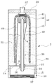
도 1 및 도 2 는 카트리지 일체형 무화기부를 구비한 전자 담배를 도시한 도면으로, 도 1 은 전자 담배의 결합 사시도이고, 도 2 는 결합 단면도이다. 1 and 2 are views showing an electronic cigarette having a cartridge-integrated atomizer, FIG. 1 is a perspective view of a combination of electronic cigarettes, and FIG.
도면을 참조하면, 배터리부(1)는 무화기부(2)의 하면으로 결합되어 무화기부(1) 내의 심지 열선에 전원을 공급하는 데, 배터리부(1)의 상단부 외주면에는 나사산이 형성되어 무화기부(2)의 하단 내주면(12)과 나사 결합된다. Referring to the drawings, the battery unit 1 is coupled to the lower surface of the
배터리부(1)는 무화기부(2)의 몸체(10)의 하단과 나사체결되는 부분에 일측 단자가 형성되고, 상단 중심부에 타측 단자가 형성되어, 각각 무화기부(2)의 몸체(10), 및 공기 유동관(30)과 전기적으로 접촉된다.The battery unit 1 has one terminal formed at a portion screwed to the lower end of the
무화기부(2)는 카트리지 일체형 무화기로서, 몸체(10), 액상 용액통(20), 공기 유동관(30), 심지부(40), 마개부(50)를 포함한다. The
몸체(10)는 배터리부(1)와 무화기부(2)를 연결하는 연결 부분으로, 내부가 차단판(14)으로 막힌 통 형상으로 형성되며, 하단 내주면(12)으로는 나사산이 형성되어 배터리부(1)와 나사결합될 수 있도록 구성된다. 몸체(10)는 금속 소재 또는 금속 소재로 코팅되어 전기가 소통될 수 있는 도전체로 형성되므로, 내주면(12)과 배터리부(1)의 상단 외주면이 나사체결 될 때, 전기적 연결이 이루어진다.
몸체(10) 외면에는 차단판(14)의 하부 공간과 외부와의 공기 소통을 가능하게 하는 공기 유입홀(15)이 형성되어 공기 유동관(30)으로 공기를 공급한다. 몸체(10)의 차단판(14) 중심부에는 공기 유동관(30)을 위한 삽입홀(16)이 형성된다. The outer surface of the
액상 용액통(20)은 몸체(10)의 상부로 결합되며 내부에 액상 용액(21)이 저장된다. 액상 용액(21)은 심지(45)를 통해 공급되어 열선(41)에 의해 기화됨으로써 수증기(연기)가 된다. 액상 용액통(20)의 상단에는 마개부(50)가 구비된다. 마개부(50)는 흡입이 이루어질 수 있도록 흡입구(52)를 구비한 상태로 액상 용액통(20)의 상단을 막으며, 마개부(50)의 하단은 심지 지지체(42)의 상단과 접촉한다. The
공기 유동관(30)은 패킹(37)을 개재하여 몸체(10)의 삽입홀(16)에 결합되며 액상 용액통(20) 내부에서 상부로 연장되어 심지 지지체(42)의 홀에 끼워진다. 사용자가 마개부(50)에 입을 대고 흡입을 하면 공기 유입홀(15)을 통해 유입된 공기가 공기 유동관(30)을 통해 이동하고, 유동 공기는 심지(45)에서 열선(42)에 의해 기화된 수증기가 함께 흡입된다. The
공기 유동관(30)은 금속과 같은 도전 소재로 이루어지거나 도전 소재로 코팅되어 도전체를 이룬다. 공기 유동관(30)은 패킹(37)에 의해 몸체(10)와 전기적으로 절연되면서 차단판(14)을 관통하여 하부로 돌출되는 데, 하부 돌출부(33)는 무화기부(2)가 배터리부(1)와 체결시 배터리부(1) 상면의 접점과 접촉하여 전기적으로 연결된다. The
심지부(40)는 심지 지지체(42)와, 심지(45), 열선(41) 및 연결 도선(48)을 포함한다. 심지 지지체(42)는 하부로부터 공기 유동관(30)이 삽입되는 중공의 통체로 형성된다. 심지 지지체(42)에는 심지(45)가 끼워져 고정되고 심지(45)의 중간부에는 열선(41)이 감겨져 있다. 심지(45)는 양단은 연장되어 액상 용액통(20) 하부로 향하고 액상 용액(21)에 담겨진다. 따라서 액상 용액(21)은 모세관 현상에 의해 심지(45)를 따라 이동하여 심지(45) 전체가 액상 용액에 젖게 된다. The
심지 지지체(42)의 내부에 위치한 심지(45) 부분에는 감겨진 열선(41)은 발열하여 심지(45)에 젖어있는 액상 용액을 기화시켜 수증기를 발생시킨다. The
연결 도선(48)은 열선(41)에 전원을 공급하기 위한 것으로, 양측 연결 도선(48)의 일단 각각은 열선(41)에 납땜(a) 되고, 각각이 아래로 연장되어 일측 연결도선(48)의 타단은 몸체(10)에 납땜(a) 되고, 타측 연결 도선(48)의 타단은 공기 유동관(30)의 외주면에 납땜(a) 된다. 몸체(10) 및 공기 유동관(30)이 도전체로 형성되므로, 배터리부(10)와 무화기부(2)가 나사 체결될 때, 열선(41)으로의 전원 공급경로가 완성되어, 배터리부(1) 온 상태에서 열선(41)에 전원이 공급되고, 액상 용액의 기화가 이루어질 수 있다. The connecting
이와 같은 구조의 전자담배에서는 다음과 같은 단점이 있다. The electronic cigarette of such a structure has the following disadvantages.
첫째로, 납땜 성분에 의해 인체에 유해한 성분이 발생할 가능성이 있다. 인체에 무해한 성분으로 된 납땜이 있을 수 있지만, 납땜 부분에서 인체에 유해한 성분이 용출될 가능성이 전혀 없는 것은 아니며, 건강에 민감한 소비자에게 제품 신뢰성을 떨어뜨리는 요인이 된다. First, there is a possibility that a component harmful to the human body is generated by the soldering component. There may be solders with ingredients that are harmless to the human body, but there is no possibility of harmful components eluting from the soldering parts, which is a factor that reduces product reliability to health-conscious consumers.
둘째, 납땜 공정으로 제작 공정이 어려워진다. 양측 연결 도선 각각의 일단을 열선의 양 단부와 납땜되고 타단 각각을 액상 용액통 내부에서 몸체 및 공기 유동관에 납땜하여야 하는 데, 전자 담배는 소형 부품들로 이루어진 소형 장치이므로 납땜 작업이 쉽지 않고 이로 인해 작업 부하의 증가 및 제조비용의 상승 요인이 된다.Second, the soldering process makes the manufacturing process difficult. One end of each connecting wire should be soldered to both ends of the heating wire, and the other end should be soldered to the body and the air flow tube inside the liquid container. Since the e-cigarette is a small device made of small parts, it is not easy to solder. This increases the workload and increases manufacturing costs.
셋째, 전자 담배 사용을 위해 사용자가 부담하는 비용이 증가한다. 일반적으로 전자 담배는 열선과 심지의 수명 때문에 일정기간 사용 후 교체해 주여야 한다. 전자담배는 열선 및 심지 교체 없이 오래기간 동안 사용을 지속하면 열선에 각종 이물질이 침착되어 연기 발생량이 저하되고, 침착된 이물질에 기인하여 건강에 해로운 물질이 함유된 연기가 발생되게 되는 문제점이 있다. 그런데 상술된 구조는 납땜된 고정 접점 구조이기 때문에 사용자가 열선 및 심지만을 교체하는 것을 불가능하여, 무화기부 전체를 교체해야 한다. 일정기간 사용 후 열선 및 심지 때문에 무화기부 전체를 새로이 구입해야 하기 때문에 제품 가격이 실질적으로 비싸지게 되고, 무화기부에 고급 재질의 부품을 사용하기가 어려워진다. 이러한 단점을 해결하기 위해서는 심지와 열선의 교체시에 교체 부품을 최소화할 수 있는 구조의 전자 담배가 개발되어야 한다.Third, the cost paid by the user for using the electronic cigarette increases. In general, e-cigarettes need to be replaced after a certain period of time due to heat and wick life. If the e-cigarette is used for a long time without replacing the heating wire and the wick, various foreign matters are deposited on the heating wire, resulting in a decrease in the amount of smoke generation, and the smoke containing the harmful substances due to the deposited foreign matters is generated. However, since the above-described structure is a fixed contact structure soldered, it is impossible for the user to replace only the heating wire and the core, so that the entire atomizer portion needs to be replaced. After a certain period of time, because of the heating wire and the wick, the entire atomizer must be newly purchased, and the price of the product becomes substantially expensive, and it becomes difficult to use high-quality materials in the atomizer. In order to solve these drawbacks, electronic cigarettes having a structure capable of minimizing replacement parts when replacing wicks and heating wires should be developed.
넷째, 전자 담배는 액상 용액 수증기를 기화시켜 흡입하는 것으로 액상 용액의 충전이 필요한 데, 상술한 구조의 전자 담배는 액상 용액의 충전이 어려운 단점이 있었다. Fourth, the e-cigarette is required to fill the liquid solution by vaporizing the liquid solution vapor by inhalation, the electronic cigarette of the above-described structure has a disadvantage that it is difficult to fill the liquid solution.
다섯째, 상술한 구조의 전자 담배는 비사용 시에도 사용 시와 동일하게 심지로 액상 용액이 공급되므로 액상 용액이 방울 형태로 공기 유동관 내부로 떨어지는 현상이 발생하는 문제점이 있다. 액상 용액이 공기 유동관 내부로 떨어지는 경우 배터리부 접점의 오염 및 손상을 초래할 수 있다. Fifth, the electronic cigarette of the above-described structure has a problem that the liquid solution is supplied into the wick in the same manner as in use even when not in use, the liquid solution falls into the air flow tube in the form of droplets. If the liquid solution falls into the air flow tube, it may cause contamination and damage of the battery contact.
한편, 전자담배 사용자 중 기호에 따라 빡빡한 흡입압 선호하거나 쉽게 흡입되는 것을 선호하는 등 사람마다 취향이 다르다. 그러나 상술된 구조의 전자담배에서는 흡입 압력을 기호에 따라 조절할 수 없으므로 선택의 여지없이 같은 흡입압의 제품을 사용하여야 한다. 흡입압 기호에 따라 조정을 할 수 있는 제품에 대한 요구가 있다. On the other hand, e-cigarette users have different tastes, such as preference for tight suction pressure or easy suction according to their preferences. However, in the electronic cigarette of the above-described structure, the suction pressure can not be adjusted according to the preference, so the product of the same suction pressure should be used without a choice. There is a need for a product that can be adjusted to the suction pressure symbol.
한편, 상술된 구조의 전자담배는 심지 지지체 상에 위치한 심지에 감겨진 열선에 의해 심지에 젖어든 액상 용액이 기화되어 사용자에게 흡입될 때 기화되지 않은 고온의 액상 용액 방울이 함께 흡입될 우려가 있다. 뜨겁게 달궈진 철판에 물을 조금 부는 경우 물이 구슬처럼 방울지면서 튀는 현상과 유사하게, 전자 담배에서는 열선과 맞닿은 용액 중 일부가 기화되지 않고 방울 형태로 튀는 용액 튐 현상이 발생한다. 이러한 용액 튐 현상이 발생할 때 사용자가 흡입을 하는 경우 용액 방울이 수증기와 함께 사용자에게 흡입될 수 있고, 이로 인해 국소적인 화상 및 목 따가움 현상 등이 발생할 우려가 있다. 그런데 상술된 구조에서는 수증기의 유동 경로가 직선 경로서 흡입압이 직접적으로 작용하므로, 용액 튐 현상에 의해 발생한 고온 용액 방울이 사용자에게 함께 흡입될 우려가 있다.
On the other hand, the electronic cigarette of the above-described structure may be inhaled together with the liquid droplets of the hot liquid that is not vaporized when the liquid solution wet to the wick is vaporized by the hot wire wound on the wick located on the wick support is inhaled by the user. Similar to the phenomenon of water splashing like a bead when a small amount of water is poured onto a hotly heated iron plate, in e-cigarette, a solution splashing occurs in which some of the solution contacting the hot wire does not vaporize but splashes in the form of drops. When the user inhales when such a solution splash occurs, the droplet may be inhaled by the user with water vapor, which may cause local burns and sore throat. However, in the above-described structure, since the suction pressure acts directly on the flow path of the water vapor in a straight path, there is a possibility that the hot solution droplets generated by the solution splash phenomenon are sucked together by the user.
본 발명은 상기와 같은 문제점을 해결하기 위해 안출된 것으로, 액상 용액의 충전이 용이한 조절용 상부 캡을 구비한 전자 담배를 제공하는 것을 목적으로 한다. The present invention has been made to solve the above problems, it is an object of the present invention to provide an electronic cigarette having an upper cap for adjusting the liquid solution easy to fill.
또한, 본 발명은 비 사용시에는 심지를 통한 액상 용액 이동을 억제할 수 있는 구조의 전자 담배를 제공하는 것을 목적으로 한다. In addition, an object of the present invention is to provide an electronic cigarette having a structure that can suppress the movement of the liquid solution through the wick when not in use.
또한, 본 발명은, 열선이 무 납땜 방식으로 전원 소통되도록 연결될 수 있는 심지 모듈을 제공함으로써, 열선 및 심지의 교체 시에 교환되는 부품 수를 최소화할 수 있는 전자 담배를 제공하는 것을 목적으로 한다. In addition, an object of the present invention is to provide an electronic cigarette that can minimize the number of parts exchanged at the time of replacement of the hot wire and the wick by providing a wick module that can be connected so that the hot wire is power communication in a solderless manner.
또한, 본 발명은 조립 공정을 단순화하여 전자 담배의 제조를 용이하게 할 수 있는 전자 담배용 심지 모듈 및 전자 담배를 제공하는 것을 목적으로 한다. In addition, an object of the present invention is to provide an wick module and an electronic cigarette for an electronic cigarette that can simplify the assembly process to facilitate the manufacture of the electronic cigarette.
또한 본 발명은 흡입압을 사용자의 기호에 맞게 조절할 수 있는 전자담배를 제공하는 것을 목적으로 한다. In addition, an object of the present invention is to provide an electronic cigarette that can adjust the suction pressure according to the user's preference.
또한, 본 발명은 용액 튐 현상에 의하여 튀어 오른 고온의 용액 방울이 사용자에게 흡입되는 것을 방지할 수 있는 전자담배를 제공하는 것을 목적으로 한다.In addition, an object of the present invention is to provide an electronic cigarette that can prevent the high-temperature solution drops splashed by the solution splash phenomenon to be inhaled to the user.
본 발명은 상기한 목적을 달성하기 위해, 상하단이 개방된 중공의 액상 용액통; 상기 액상 용액통의 하단으로 결합되고 상기 액상 용액통의 하단을 막는 차단판이 구비된 연결 탭; 상기 액상 용액통 내부에 배치되는 것으로, 관통홀이 형성된 중공의 통체로 이루어지고 심지가 삽입 지지되기 위한 한 쌍의 심지 삽입홈이 형성된 심지 지지체와; 상기 심지 삽입홈에 끼워져 고정되는 심지와; 상기 심지 지지체 내에 위치하는 심지의 중간부에 감겨지는 열선을 구비한 심지부; 상기 액상 용액통의 상단 내주면에 끼워지는 중공의 몸체로 형성되며 내주면에 나사 결합부가 형성된 바디와; 상기 바디에 대하여 승강 가능하게 결합되는 마개부로서, 외주면에 상기 바디의 내주면과 체결되는 나사 결합부가 형성된 중공의 통체로 형성되고 중공의 바닥면에는 관통구멍이 형성된 마개부 몸체와, 상기 관통구멍과 연통되는 중공을 구비하며 흡입이 이루어지는 마우스팁을 구비한 마개부를 포함하는 조절형 상부 캡; 을 포함하는 전자 담배를 제공한다. The present invention, in order to achieve the above object, the upper and lower end of the hollow liquid solution container; A connection tab coupled to a lower end of the liquid solution container and provided with a blocking plate blocking a lower end of the liquid solution container; A wick support disposed in the liquid solution container and formed of a hollow cylinder having a through hole and having a pair of wick insertion grooves for inserting and supporting the wick; A wick inserted into and fixed to the wick insertion groove; A wick having a heating wire wound around an intermediate portion of the wick positioned in the wick support; A body formed of a hollow body fitted to an upper inner circumferential surface of the liquid solution container and having a screw coupling portion formed on an inner circumferential surface thereof; A stopper portion coupled to the body so as to be lifted and lowered, the stopper body having a through-hole formed on the outer circumferential surface thereof and having a screw engaging portion fastened to the inner circumferential surface of the body, and the through hole formed on the bottom surface of the hollow; An adjustable upper cap having a hollow communicating with it and including a stopper having a mouth tip on which suction is made; It provides an electronic cigarette comprising a.
본 발명에 의하면, 상기 바디의 외주면에는 상기 액상 용액통의 상단 상부 위치에, 내주면에 나사 결합부가 형성된 바디 고정링이 체결된다. According to the present invention, a body fixing ring having a screw coupling portion formed on an inner circumferential surface is fastened to an upper upper position of the liquid solution container on an outer circumferential surface of the body.
본 발명에 의하면, 상기 바디의 외주면에는 상기 액상 용액통의 상부 위치에 내주면에 상기 바디의 외주면과 체결되는 나사 결합부가 형성된 용액통 커버 고정링이 체결되되, 상기 용액통 커버 고정링은 외주면 상단에서 외측으로 돌출되는 걸림턱이 구비되며, 상기 액상 용액통을 내부에 수용하는 중공의 통체로 형성되고, 상단 내주면이 상기 용액통 커버 고정링의 외주면에 끼워지고 하단 내주면이 상기 연결 캡의 외주면에 끼워져 고정되는 용액통 커버를 포함하여, 상기 용액통 커버를 상부로 밀어올리는 경우 상부 캡이 함께 이탈되도록 형성된다.According to the present invention, the outer circumferential surface of the body is fastened to the liquid container cover fixing ring formed with a screw coupling portion is fastened to the outer circumferential surface of the body on the inner circumferential surface at the upper position of the liquid solution container, the solution cylinder cover fixing ring is the upper end of the outer circumferential surface It is provided with a locking projection protruding outward, and formed of a hollow cylinder for accommodating the liquid solution container therein, the upper inner peripheral surface is fitted to the outer peripheral surface of the solution container cover fixing ring and the lower inner peripheral surface is fitted to the outer peripheral surface of the connection cap Including a fixed solution container cover, when the solution container cover is pushed upward, the upper cap is formed to be separated together.
본 발명에 의하면, 상기 심지부는 상기 심지 지지체의 상부를 덮는 심지 캡을 포함하되, 상기 심지 캡은 상기 심지 지지체의 상단이 내부로 끼워지는 중공을 가지며 상기 심지 지지체의 심지 삽입홈에 대응하여 주면에 상기 심지가 삽입될 수 있는 상부측 심지 삽입홈이 형성된 심지 캡 바디와, 상기 심지 캡 바디의 상면에서 상기 심지 캡 바디와 단차를 이루며 상부로 연장 형성되고, 상단이 막힌 형상이고 측면으로 수증기 배출홀이 형성된 수증기 배출부를 포함하고, 상기 수증기 배출부는 마개부의 관통구멍에 배치되고, 상기 관통구멍의 하단 주변부가 상기 심지 캡 바디의 상면과 접촉하도록 배치된다.According to the present invention, the wick portion includes a wick cap covering an upper portion of the wick support, wherein the wick cap has a hollow in which an upper end of the wick support is fitted into the main surface corresponding to the wick insertion groove of the wick support. A wick cap body having an upper wick insertion groove into which the wick can be inserted, and formed on the upper surface of the wick cap body so as to form a step with the wick cap body and extending upward, the top of which is clogged, and a vapor discharge hole to the side And a water vapor discharge portion formed therein, wherein the water vapor discharge portion is disposed in the through hole of the plug portion, and the lower periphery of the through hole is disposed in contact with the upper surface of the wick cap body.
본 발명에 의하면, 상기 심지부는, 상기 심지 지지체의 하부 부분이 내부로 삽입되는 중공의 통체로 형성되고, 상기 중공의 일부는 상기 심지 지지체의 중공과 연통되는 관통홀을 이루며, 상기 열선의 일단이 연장되어 상기 심지 지지체와의 사이에 개재되어 고정되도록 하는 도전체로 된 하부 도전체와; 상기 하부 도전체의 외부로 씌워지는 중공의 통체로 형성되고 절연체로 된 하부 절연체를 포함하고, 중공으로 형성되어 외부에서 유입된 공기의 유동 통로가 되는 것으로, 상기 연결 캡의 삽입홀을 관통하여 설치되되 상기 차단판의 하부로 하단 접점부가 위치한 상태로 상기 액상 용액통 내부로 연장되고 상단 접점부가 상기 하부 도전체의 관통홀 내로 삽입되어 그 내주면과 접촉함으로써 전기적 연결이 이루어지는 공기 유동관; 상기 액상 용액통의 내부에서 상기 하부 절연체와 상기 연결 캡의 차단판 사이에 개재되어 설치되고 상기 열선의 타단과 접촉하는 도전체로 된 외측 도전체인 탄성 스프링을 포함한다. According to the present invention, the wick portion is formed of a hollow cylinder into which a lower portion of the wick support is inserted, and the portion of the hollow forms a through hole communicating with the hollow of the wick support, and one end of the hot wire A lower conductor made of a conductor extending and interposed between and fixed to the wick support; The lower insulator is formed of a hollow cylinder covering the outside of the lower conductor, and includes a lower insulator made of an insulator, and is formed through the insertion hole of the connection cap to be a flow passage of air introduced from the outside. An air flow tube extending into the liquid solution container while the lower contact portion is positioned below the blocking plate, and the upper contact portion is inserted into the through hole of the lower conductor to be in electrical contact with the inner circumferential surface thereof; And an elastic spring which is installed between the lower insulator and the blocking plate of the connection cap in the liquid solution container and is an outer conductor made of a conductor contacting the other end of the heating wire.
본 발명에 의하면, 상기 공기 유동관은 상단 접점부와 하단 접점부 사이에 중간부를 구비하되, 상기 중간부는 상기 상단 접점부 보다 작은 직경으로 형성되거나 외주면에 절연 부재를 포함하여 상기 상단 접점부가 상기 하부 도전체를 이탈하여 상기 심지 지지체 내로 이동한 경우에는 전기 연결이 차단된다. According to the present invention, the air flow tube is provided with an intermediate portion between the upper contact portion and the lower contact portion, wherein the intermediate portion is formed with a smaller diameter than the upper contact portion or includes an insulating member on the outer peripheral surface, the upper contact portion is the lower conductive When the sieve leaves and moves into the wick support, the electrical connection is interrupted.
본 발명에 의하면 상기 연결 캡은, 상단은 상기 액상 용액통의 하단 내주면으로 결합되고 하단 내주면에 나사 결합부가 형성되는 중공의 연결링; 상단 외주면에 상기 연결링의 하단 내주면과 결합하는 나사 결합부가 형성되고, 상기 차단판을 구비하며, 상기 차단판의 아래 위치로 나사 결합부가 형성된 상단 외주면 아래의 외주면에는 크기가 서로 다른 복수의 관통된 공기 유입홀이 형성되며, 하단 내주면에는 나사 결합부가 형성되어 배터리부와 결합되는 중공의 연결 캡 바디; 및 상기 연결 캡 바디의 상기 공기 유입홀이 형성된에 끼워지는 링 형상의 부재로서 상기 복수의 공기 유입홀 중 선택된 어느 하나를 외부로 노출하여 흡입압이 조절가능하게 하는 공기 구멍을 가진 흡입압 조절링을 포함한다.
According to the present invention, the connection cap, the upper end is coupled to the lower inner circumferential surface of the liquid solution container and the hollow connection ring formed with a screw coupling portion on the lower inner circumferential surface; A screw engaging portion is formed on the upper outer circumferential surface and engages with the lower inner circumferential surface of the connection ring. An air inlet hole is formed, and a hollow coupling cap body having a screw coupling portion formed at a lower inner circumferential surface thereof and coupled to the battery unit; And a ring-shaped member fitted to the air inlet hole of the connection cap body, the inlet pressure adjusting ring having an air hole for exposing any one selected from the plurality of air inlet holes to the outside to adjust the suction pressure. It includes.
본 발명에 의하면, 액상 용액통의 상단 개방이 용이하므로, 액상 용액의 충전이 용이하게 된다. 또한 본 발명에 의하면, 비 사용시에는 심지를 통한 액상 용액 이동을 억제할 수 있고 심지를 통한 액상 용액의 이동량을 규제하여 수증기 량을 조절할 수 있다. 또한, 본 발명은, 열선이 무 납땜 방식으로 전원 소통되도록 연결될 수 있는 심지 모듈을 제공함으로써, 열선 및 심지의 교체 시에 교환되는 부품 수를 최소화할 수 있다. 또한, 본 발명은 조립 공정을 단순화하여 전자 담배의 제조를 용이하게 한다. 또한, 본 발명은 흡입압을 사용자의 기호에 맞게 조절할 수 있게 한다. 또한, 본 발명은 용액 튐 현상에 의하여 튀어 오른 고온의 용액 방울이 사용자에게 흡입되는 것을 방지할 수 있다.
According to the present invention, since the upper end of the liquid solution container is easy to open, the filling of the liquid solution is easy. In addition, according to the present invention, when the non-use can suppress the movement of the liquid solution through the wick, it is possible to control the amount of water vapor by regulating the amount of movement of the liquid solution through the wick. In addition, the present invention, by providing a wick module that can be connected so that the hot wire is in power communication in a solderless manner, it is possible to minimize the number of parts exchanged during the replacement of the hot wire and the wick. In addition, the present invention simplifies the assembly process to facilitate the manufacture of electronic cigarettes. In addition, the present invention allows to adjust the suction pressure to the user's preference. In addition, the present invention can prevent the high-temperature solution drops splashed by the solution splash phenomenon to be inhaled by the user.
도 1 는 카트리지 일체형 무화기를 구비한 전자 담배의 결합 사시도이다.
도 2 는 카트리지 일체형 무화기부를 구비한 전자 담배의 결합 단면도이다.
도 3 은 본 발명에 따른 전자 담배의 부분 분해도이다.
도 4 는 본 발명에 따른 전자 담배 무화기부의 결합 단면도이다.
도 5 는 본 발명에 따른 전자 담배에서 액상 용액통, 용액통 커버, 및 상부 캡의 부품 사시도이다.
도 6 은 도 5 에 도시된 부품들의 단면도이다.
도 7 은 본 발명에 따른 전자 담배에서 심지부의 부품 및 공기 유입관, 탄성 스프링을 도시한 부품 사시도이다.
도 8 은 본 발명에 따른 전자 담배에서 심지부 일부 부품의 단면도이다.
도 9 는 본 발명에 따른 전자 담배에서 공기 유동관의 상단 접점부 위치에 따른 전자 담배의 온 오프 동작을 설명하기 위한 도면이다.
도 10 은 본 발명에 따른 전자 담배에서 연결 캡의 부품도이다. 1 is a combined perspective view of an electronic cigarette with a cartridge integral atomizer.
2 is a cross sectional view of an electronic cigarette having a cartridge-integrated atomizer;
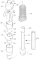
3 is a partial exploded view of an electronic cigarette according to the present invention.
4 is a cross-sectional view of a combination of the electronic cigarette atomizer according to the present invention.
5 is a perspective view of parts of the liquid solution container, the solution container cover, and the upper cap in the electronic cigarette according to the present invention.
6 is a cross-sectional view of the parts shown in FIG. 5.
7 is a perspective view showing the parts of the wick, the air inlet pipe, the elastic spring in the electronic cigarette according to the present invention.
8 is a cross-sectional view of a part of the wick part in the electronic cigarette according to the present invention.
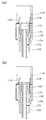
9 is a view for explaining the on-off operation of the electronic cigarette according to the position of the upper contact portion of the air flow tube in the electronic cigarette according to the present invention.
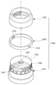
10 is a part view of a connection cap in an electronic cigarette according to the present invention.
이하, 첨부된 도면을 참조하여 본 발명의 실시예들을 보다 상세하게 설명한다. Hereinafter, exemplary embodiments of the present invention will be described in detail with reference to the accompanying drawings.
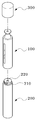
도 3 은 본 발명의 실시예에 따른 전자담배의 부분 분해도이다. 도면을 참조하면, 본 발명의 실시예에 따른 전자담배는, 무화기부(100)와 배터리부(200)를 포함한다. 3 is a partial exploded view of an electronic cigarette according to an embodiment of the present invention. Referring to the drawings, the electronic cigarette according to an embodiment of the present invention, the
배터리부(200)는 무화기부(100)의 하면으로 결합되는 데, 내부에 배터리(미도시)를 수용한다. 배터리부(200)의 상단 외주면(210)에는 나사산이 형성되고, 상면에는 홈 형태의 접점(220)이 형성된다. 배터리부(200)는 내부에 수용된 배터리의 양 단자와 외부를 연결하는 양 접점을 구비하는 데, 일 접점은 외주면(210) 나사산 형성부에 형성되고, 다른 접점은 상면 홈 형태의 접점(220)에 형성된다. The
따라서 본 발명에 의하면 무화기부(100)와 배터리부(200)가 체결될 때 무화기부(100)의 하단 내주면과 배터리부의 외주면(210)이 접촉하고, 공기 유동관의 하단이 홈 형태의 접점(220)과 접촉하여 전기적 연결이 이루어진다. Therefore, according to the present invention, when the
무화기부(100)의 상부에는 뚜껑(300)이 구비된다. The
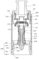
도 4 는 본 발명의 실시예에 따른 무화기부(100)의 결합 단면도이고, 도 5 는 액상 용액통(110), 용액통 커버(115), 및 상부 캡(120)의 부품 사시도이고, 도 6 은 도 5 에 도시된 부품 들의 단면도이고, 도 7 은 심지부의 부품 및 공기 유입관(175), 탄성 스프링(179)을 도시한 부품 사시도이고, 도 8 은 심지부 일부 부품의 단면도이며, 도 9 는 공기 유동관의 상단 접점부 위치에 따른 전자 담배의 온 오프 동작을 설명하기 위한 도면이며, 도 10 은 연결 캡(180)의 부품도이다. 4 is a cross-sectional view of the
도면을 참조하면, 본 발명에 따른 무화기부(100)는, 액상 용액통(110)과, 용액통 커버(115), 상부 캡(120), 심지부, 공기 유동관(175), 외측 도전체인 탄성 스프링(179) 및 연결 캡(180)을 포함한다. Referring to the drawings, the
액상 용액통(110)은 중공의 통체로 형성되고, 상단으로 상부 캡(120)과 결합되고 하단으로 연결 캡(180)과 결합되어, 내부에 액상 용액을 수용한다. 액상 용액은 심지를 통해 열선이 감겨진 부분으로 공급된다. 액상 용액통(110)은 투명 소재로 형성된다. The
용액통 커버(115)는 액상 용액통의 둘러싸도록 외부에 씌워지며 상단으로 상부 캡(120), 하단으로 연결 캡(180)과 결합된다. 용액통 커버(115)는 불투명 소재로 형성되고, 외면에 액상 용액통(110) 내부에 충전된 액상 용액의 레벨을 확인할 수 있는 게이지 창(116)이 형성된다. 게이지 창(116)은 투명하게 형성되거나 길이방향으로 길게 연장된 홀 형태로 형성된다. The
상부 캡(120)은 바디(121)와 마개부(128)를 포함한다. 바디(121)는 액상 용액통(110)의 상단에 액상 용액통(110)의 내부로 끼워질 수 있는 중공의 원통형 몸체로 형성되며, 내부의 중공 상부측(122)이 중공 하부측(123) 보다 내경이 작도록 단차져 있다. 중공 상부측(122) 내주면에는 나사산이 형성된다. 바디(121)의 외주면에는 나사산이 형성된 나사 결합부(125)가 구비된다. 나사 결합부(125)는 외주면의 하단부의 상부로 형성될 수 있다. 바디(121)는 액상 용액통(110)의 내주면과 끼움 결합된다. The
마개부(128)는 마개부 몸체(129)와 마우스팁(133)을 포함한다. The
마개부 몸체(129)는 마우스팁(133)의 하단이 상부로부터 삽입 고정되는 중공의 통체로 형성되며 외주면에 나사산이 형성된 나사 결합부(130)를 구비한다. 나사 결합부(130)는 형성 길이는 바디(121)에 대한 마개부 몸체(129)의 상승 높이를 조절하기 위한 것으로 도면과 같이 부분적으로 형성될 수 있다. 마개부 몸체(129)의 하단 외주면에는 외측으로 확대된 외측 걸림턱부(131)를 구비하고, 중공 바닥면에는 관통구멍(132)이 관통 형성된다. 외측 걸림턱부(131)는 바디(121)에 대한 마개부 몸체(129)에 대한 상승을 규제한다. The
마우스팁(133)은 중공으로 이루어져 사용자가 입에 대고 흡입을 할 수 있게 형성된다. 본 실시예에서는 제작 및 조립의 용이성을 위해 마개부(129)를 마개부 몸체(129) 및 마우스팁(133)을 별개의 부재로 형성 조립한 예를 설명하고 있으나 일체의 부재로 형성될 수 있다.
마개부(128)의 하단은 심지부의 심지 캡(160)의 심지 캡 바디(161)를 눌러 가압한다. 따라서 마개부(128)와 심지 캡(160) 사이 공간으로의 공기 유동은 차단되고, 공기는 수증기와 함께 심지 지지체(140)를 거쳐 심지 캡(160)의 수증기 배출홀(164)을 통해 유동한다. The lower end of the
바디(121)의 외주면에는 바디 고정링(135)이 체결된다. 바디 고정링(135)은 내주면에 나사산이 형성되어 바디(121)의 나사 결합부(130)에 나사체결된다. The
바다(121)의 외주면에는 바디 고정링(135)의 상부로 용액통 커버 고정링(137)이 체결된다. 용액통 커버 고정링(137)은 용액통 커버(115)의 내측 상단으로 삽입된 고정된다. 용액통 커버 고정링(137)의 외주면 상단에는 외측으로 걸림턱(138)이 형성된다. On the outer circumferential surface of the
용액통 커버(115) 커버는 상단이 용액통 커버 고정링(137)에 끼움 결합되고, 하단이 연결 캡 바디(181)에 끼움 결합된다.The
본 발명의 실시예에 따른 상부 캡(120)은 액상 용액 충전의 용이성과 사용자의 기호에 맞는 수증기 량 조절을 용이하게 한다. The
먼저, 마개부(128)는 바디(121) 내측으로 나사체결되어 승강이 용이하게 조절될 수 있다. 따라서 마개부(128)를 돌려 바디(121)에 대하여 마개부(128)을 상승시키면 심지 캡(160)을 누르는 힘이 제거되고, 마개부(128) 하단과 심지 캡(160) 사이의 공간이 열린다. 따라서 마우스팁(133)을 통해 주사기 등으로 용액을 주입하게 되면 용액은 액상 저장통(110) 내부로 들어간다. First, the
한편, 마개부(128)를 반대 방향으로 돌려 바디(121)에 대하여 마개부(128)를 하강시키면 심지 캡 바디(161)를 누르는 힘이 증가한다. 아래에서 보다 상세하게 설명되지만 심지(148)는 심지 지지체(140)의 심지 삽입홈(144)과 상부 캡(160)의 상부 심지 삽입홈(162)을 통과하여 연장하기 때문에 상부 캡(160)이 눌려지면 상부 심지 삽입홈(162)이 심지(148)를 누르게 된다. 즉 심지(148)가 가압되므로 심지(148) 중앙부에 열선(149)이 감긴 부분으로 공급되는 심지(148)를 따라 공급되는 액상 용액의 양이 줄어들게 된다. 심지(148)를 통한 액상 용액 공급량의 조절은 비사용시에 특히 중요한데, 열선(149)에 전원이 공급되지 않더라도 심지(148)는 모세관 현상에 의하여 액상 용액으로 젖어있다. 그런데, 비사용 상태가 지속되면 심지(148) 중앙부에 스며든 액상 용액이 물방울과 같이 맺히면서 심지 지지체(140) 내부를 통하여 공기 유동관(175)으로 떨어지는 현상이 발생할 수 있다. 이 경우 배터리부(200) 접점의 오염 및 고장을 초래할 수 있음은 상술한 바와 같다. 본 발명의 실시예에 의하면, 비 사용시에 마개부(128)를 아래로 이동시켜 심지 캡(160)을 가압하면 심지(148)을 따라 이동하는 액상 용액의 공급량을 줄일 수 있으므로, 비 사용시 용액 낙하 현상을 방지할 수 있다. On the other hand, by turning the
한편, 심지(148)에 공급되는 액상 용액의 양이 적으면 열선(149) 주변에서 기화되지 않고 남아 있는 액상 용액의 찌꺼기가 타면서 탄맛이 발생하는 데, 본 발명에 따르면 이 경우 마개부(128)를 약간 상승시켜 액상 용액 공급량을 늘리는 것이 가능하므로 이와 같은 문제점도 해결할 수 있다. On the other hand, if the amount of the liquid solution supplied to the
또한, 본 발명의 실시예에 따르면 마개부(128)의 하강 조절을 통해 전자 담배를 손쉽게 온 오프 조절할 수 있다. 이에 대해서는 심지부와 관련하여 아래에서 보다 상세하게 설명된다. In addition, according to the embodiment of the present invention, the electronic cigarette can be easily turned on and off by adjusting the lowering of the
또한 본 발명의 실시예에 따르면, 마개부(128)가 바디(121)에 대해서 승하강 조절되는 데, 바디(121) 역시 용액통 커버(115)를 기준으로 승하강 조절될 수 있게 구성된다. 바디(121)가 상승되면 마개부(128)가 상승할 수 있는 영역이 증대괴고, 바디(121)가 하강되면 마개부(128)가 하강될 수 있는 영역이 증대된다. In addition, according to an embodiment of the present invention, the
본 발명에 의하면 용액통 커버(115)를 이용하여 보다 용이하게 상부 캡(120)을 분리하고 액상 용액을 주입 충전할 수 있다. According to the present invention, by using the
용액통 커버(115)를 사용자가 잡고 위로 밀어 올리는 경우 용액통 커버(115)는 연결 캡 바디(181)로 부터 분리된다. 이 때, 용액통 커버(115)의 상단은 용액통 커버 고정링(137)의 걸림턱(138)에 맞닿아 용액통 커버 고정링(137)을 밀어 올리는데, 용액통 커버(137)는 바디(121)와 나사체결되어 있으므로 바디(121)가 함께 움직이고, 바디(121)에 나사 체결 방식으로 결합된 바디 고정링(135) 및 마개부(129)가 함께 들어올려진다. 즉, 용액통 커버(115)를 잡고 사용자가 위로 올리는 경우 상부 캡(120) 전체가 액상 용액통통(110)으로부터 분리되는 것이다. 이러한 과정을 통해 손쉽게 액상 용액통(110)의 상부가 개방되므로 액상 용액 주입 충전이 손쉽게 이루어질 수 있다. When the user holds the
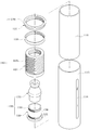
본 발명의 실시예에 따르면 심지부는, 심지 지지체(140)와, 심지(148), 열선(149), 하부 도전체(150)와 하부 절연체(156), 심지 캡(160)을 포함한다. 심지 모듈(130)은, 공기 유동관(175), 탄성 스프링(179)과 조립되어 조립체를 이룬다. According to an embodiment of the present invention, the wick includes a
심지 지지체(140)는 상하단이 개방된 중공의 통체로 형성된 것응로 심지를 지한다. 심지 지지체(140)는 상부 부분(142)과 하부 부분(143)으로 구분될 수 있고, 상부 부분(142)의 외경이 하부 부분(143)의 외경보다 큰 단차진 형상으로 형성된다. 하부 부분(143)의 중공을 이루는 관통홀(141)은 공기 유동관(175)을 통해 유입된 공기의 통로가 되며, 실시예에 따라 상단 접점부(176)가 삽입되는 통로가 된다. 관통홀(141)에는 공기 유동관(175)의 상단 접점부(176)의 상승 높이를 규제할 수 있도록 내측으로 단턱(146)이 형성된다. 상부 부분(142)의 상단에는 요홈 형상의 한 쌍의 심지 삽입홈(144)이 형성된다. 심지 삽입홈(144)은 서로 대면하여 위치하고 심지(148)의 중앙부가 끼워진다. The
심지 삽입홈(144)에 끼워져 고정된 심지(148)의 양 단은 액상 용액통(110) 내부 아래로 연장되고 그 하단이 액상 용액통 내에 담긴 액상 용액과 접촉하다. 액상 용액은 심지를 따라 이동하면서 심지(148)를 젖게 한다. Both ends of the
심지 지지체(140)에는 열선의 양 단부가 내부에서 외부로 인출될 수 있는 한 쌍의 열선 인출홀(145)이 형성된다. 열선 인출홀(145)은 서로 대향하는 위치에 형성된다. 심지 지지체(140) 내에서 심지(148)에 감겨진 열선(149)에 발열이 이루어지기 때문에 심지 지지체(140)는 세라믹 등과 같은 내열 소재로 형성된다. The
열선(149)은 심지 지지체(140) 내에 위치하는 심지(148)의 중앙부에 코일 형태로 감겨지고 양단 각각이 열선 인출홀(145)을 통해 외부로 연장된다. The
심지 지지체(140)의 하부로 금속 재질의 도전체로 이루어진 중공의 하부 도전체(150)가 끼워져 적어도 심지 지지체(140)의 하부 부분(143)을 둘러싼다. 하부 도전체(150)의 상단 일측에는 심지 지지체(140)의 외부로 연장된 일측 열선(149)과 하부 도전체(150)의 접촉을 방지하는 절개홈(151)이 형성된다. 그리고 절개홈(151)과 대향하는 위치에는 주면으로 위치 조정홀(152)이 형성될 수 있다. 하부 도전체(150)의 중공은 심지 지지체(140)가 내부로 삽입되는 결합홈(153)과 심지 지지체(140)의 관통홀(141)과 연통되는 관통홀(154)로 형성되며, 하부 도전체(150)의 관통홀(154)에는 공기 유동관(175)의 상단 접점부(176)가 삽입된다.A hollow
하부 도전체(150)의 하부로는 하부 도전체(150)를 에워싸는 결합홈(157)을 구비한 중공의 하부 절연체(156)가 결합된다. 하부 절연체(156)의 결합홈(157) 내측으로 하부 도전체(150)가 삽입된다. 하부 절연체(156)는 실리콘과 같은 절연재로 형성된다. A hollow
심지부에서의 열선(149)의 전기적 연결을 살펴보면, 심지(148)에 감겨진 열선의 양 단부는 심지 지지체(140) 내부에서 열선 인출홀(145)을 통해 외부로 연장되는 데, 일 단부는 심지 지지체(140)의 외면을 감싸는 하부 도전체(150) 내부에서 조정홀(152)로 연장되고, 타 단부는 절개홈(151)을 지나 하부 절연체(156)의 외부로 연장된다. 열선(149)의 일 단부는 하부 도전체(150) 내부에 하부 도전체(150)와 접촉하므로 하부 도전체(150)와 전기적 연결이 이루어지고, 열선(149)의 타 단부는 절개홈(151)을 통해 하부 도전체(150)와 접촉 없이 하부 절연체(156)의 외부로 연장되므로 하부 도전체(150)와 전기적으로 연결되지 않는다. 하부 절연체(156)가 하부 도전체(150)의 외부로 끼워져 이와 같은 결합 관계가 고정된다. 조립 과정을 살펴보면, 열선(149)의 일 단부를 조정홀(152)에 끼워진 상태로 약간의 장력을 주어 팽팽한 상태를 유지하면서 하부 도전체(150)를 심지 지지체(140) 외부로 끼운다. 절개홈(151)은 조정홀(152)에 대향하는 위치에 위치하므로 열선(149)의 타 단부는 자연스럽게 절개홈(151) 상에 위치하게 된다. 이 상태에서 하부 절연체(156)가 끼워지므로 열선(149)의 양 단부의 위치가 자연스럽게 조정된다. Looking at the electrical connection of the
공기 유동관(175)이 하부 절연체(156)를 통과하여 하부 도전체(150)의 관통홀(154)에 삽입되어 공기 유동관(175)의 상단 접점부(176)가 하부 도전체(150)의 관통홀(154)에 위치하게 되면, 공기 유동관(175)과 하부 도전체(150)와 전기적으로 연결된다. The
하부 절연체(156)의 외부로 인출된 열선(149)의 타 단부는 하부 절연체(156)의 외부로 끼워지는 탄성 스프링(179)과 접촉되어 전기적으로 연결된다. The other end of the
본 발명의 실시예에 따른 심지부에 의하면, 열선(149)이 연결 도선 및 납땜 없이 도전체로 된 탄성 스프링과 공기 유동관(175)과 접촉되어 이를 매개로 전기 연결이 이루어진다. 따라서 본 발명에 따르면, 열선과 심지 교체가 필요할 때 무화기부 전체를 교체하는 것이 아니라, 심지부 또는 심지부와 탄성 스프링(179) 및/또는 공기 유동관(175) 조립체를 교체하는 것만으로 열선 및 심지의 교체가 가능하여 사용자의 비용 부담을 감소시킬 수 있다.According to the wick according to the embodiment of the present invention, the
본 발명의 실시예에 따르면 심지부는 심지 캡(160)을 더 포함한다. According to an embodiment of the present invention, the wick further includes a
심지 캡(160)은 심지 지지체(140)의 상부를 덮도록 결합된다. 도 4 , 도 7 및 도 8 을 참조하면, 심지 캡(160)은 심지 지지체(140)의 상부 부분(142)의 상단이 내부로 끼워지는 중공의 심지 캡 바디(161)와, 심지 캡 바디(161)와 상면에서 상기 상면 보다 작은 외경을 가져 단차진 형태로 상부로 연장 형성되고 측면으로 수증기 배출홀(164)이 형성되는 수증기 배출부(163)를 포함한다. 조립시, 수증기 배출부는 마개부(121)의 관통구멍(132) 내에 위치하고 심지 캡 바디(161)의 상면은 관통구멍(132)의 하단 주변과 접촉된다. 이로 인해 구조적 안정성을 이루면서도 수증기 배출홀(164)을 제외한 나머지 부분으로 수증기가 유동되는 것을 보다 효과적으로 차단할 수 있다. The
심지 캡 바디(161)의 하단 주면에는 심지 지지체(140)의 심지 삽입홈(144)에 대응하는 요홈 형태의 상부측 심지 삽입홈(162)이 형성된다. 따라서 심지(148)는 심지 삽입홈(144)과 상부측 심지 삽입홈(162)을 통하여 외부로 연장된다. 따라서 상기 심지는 하부로는 상기 심지 삽입홈에 의해 상부로는 상기 상부측 심지 삽입홈에 의해 눌려질 수 있게 배치된다. 심지의 이러한 배치에 의하여 심지 캡이 마개부에 눌려지는 정도에 따라 심지를 따라 이동하는 액상 용액의 양이 조절된다. 일반적으로 전자 담배시에는 오프 상태에서도 심지의 양 끝단이 액상 용액이 담겨진 상태를 유지하는 데, 비 사용시에 열선에 감겨진 심지 부분에서 액상 용액이 액상 상태로 이탈되는 현상이 발생하고 있다. 이 경우 액상 용액은 공기 유동관으로 유입된다. 그러나 본 발명에 의하면 심지를 눌러 심지를 따라 이동하는 액상 용액의 양을 규제할 수 있으므로 이와 같은 현상을 방지할 수 있다. 또한 사용시에도 심지를 따라 열선 부분으로 공급되는 양을 조절할 수 있으므로 수증기 량을 조절할 수 있다. The upper
수증기 배출부(163)는 심지 캡 바디(161) 내부와 연통되는 중공을 구비하는데 상단은 막힌 형상이고 측면으로 수증기 배출홀(164)이 형성된다. 그리고 수증기 배출부(163)의 외면에는 수증기 배출홀(164)의 상부로 수증기 배출홀(164)의 상부를 덮는 플랜지부(165)가 형성된다. The water
심지 캡(160)으로 인하여 수증기의 유동 경로는 심지 캡(160)이 없는 경우의 직진 상방 경로에서 측면으로 유동 후 다시 상방으로 이동하는 유동 경로로 변경된다. 가열된 열선에 액상 용액이 맞닿는 경우 대부분은 기화되지만 일부 액상 용액이 기화되지 않고 고온의 방울 형태로 튀는 현상이 발생함을 상술한 바 있다. 심지 캡(160)이 없는 경우에 용액 방울이 튀는 경로와 수증기가 흡입되는 경로가 일치하므로 사용자가 흡입을 하는 경우 고온의 용액 방울이 수증기와 함께 유동하여 사용자의 입으로 흡입될 우려가 있다. 그러나 심지 캡(160)을 구비하는 경우 튄 용액은 수증기 배출부(163)의 상단에 부딪히게 되고, 곡선화된 수증기 유동 경로에 의해 수증기와 달리 용액 방울은 유동성이 저하되므로 용액 튐 현상이 발생하더라도 튄 용액이 사용자에게 흡입될 수 없다.Due to the
또한 심지 캡(160)은 액상 용액 충전 주입시에 액상 용액이 공기 유동관(175)으로 유입되는 것을 방지하는 기능을 한다. 전자 담배는 액상 용액을 사용하므로 사용시 주기적으로 액상 용액을 주입 충전하여야 하는 데, 상부 캡을 분리하여 액상 용액통(110)의 상부를 개방하고 위로부터 액상 용액을 주입하게 된다. 그런데 통상 액상 용액통(110)의 직경이 1cm 이하로 작기 때문에, 심지 캡(160)이 없는 경우, 사용자가 주위를 기울이더라도 액상 용액의 일부가 심지 지지체(140) 내부로 주입될 수 있다. 그런데 심지 지지체(140) 내부는 공기 유동관(175)과 연통되므로 액상 용액은 공기 유동관(175) 및 공기 유동관(175)을 통해 배터리부(100)의 상면으로 흘러가게 된다. 공기 유동관(175) 내부에 액상 용액이 주입된 경우 흡입 시에 기화되지 않은 액상 상태의 용액이 흡입압에 의해 흡입되어 사용자의 불쾌감을 초래하고 배터리부 상면의 접점들을 오염시키기 때문에 세척 또는 수리가 필요하게 된다. 그러나 본 발명에 의하면 심지 지지체(140) 내부와 연통되는 수증기 배출홀(164)이 측면 방향으로 형성되어 있을 뿐만 아니라, 플랜지부(165)가 수증기 배출홀(164)을 덮고 있으므로 액상 용액을 액상 용액통 상부에 주입하더라도 액상 용액이 심지 지지체(140) 내부로 들어가는 것을 방지할 수 있으며 용액 주입 후 심지 캡(160) 상부를 닦아주는 간단한 과정으로 용액 주입을 마무리할 수 있게 된다. In addition, the
도 9 및 도 10 은 본 발명에 따른 전자 담배의 실시예에서 심지 캡(160)의 다른 실시예를 도시한 도면이다. 9 and 10 show another embodiment of the
도 9 및 도 10 을 참조하면, 심지 캡(160)은 심지 지지체(140)의 상단에 씌워져 심지 지지체(140) 상단을 덮는 중공의 상부 캡 바디(161a)와 수증기 배출부(163a)를 구비하는 데, 수증기 배출부(163a)는 내주면(166a)에 나사산이 형성된 중공의 하부 부분(166)과 하부 부분(166)의 중공을 통해 나사 결합 방식으로 체결되는 마개 형태의 상부 부분(167)을 포함한다. 상부 부분(167)의 외주면(167a)에는 나사산이 형성되어 있으며 상단은 외측으로 확장된 플랜지부(165a)가 형성된다. 하부 부분(167)의 상단 주면에는 요홈 형태로 수증기 배출홀(164a)이 형성된다. 9 and 10, the
하부 부분(166)이 심지 캡 바디(161a)의 하부로 부터 삽입된 후 하부 부분(166)의 상부로 부터 상부 부분(167)이 체결되는 데, 도 10에서 보이는 바와 같이 상부 부분(167)의 체결 정도에 따라 수증기 배출홀(164a)의 개도를 조절할 수 있게 된다. 수증기 배출홀(164a)은 흡입 시 액상 용액이 기화된 수증기가 제공되는 통로이므로 수증기 배출홀(164a)의 개도는 흡입압과 관련된다. 즉, 빡빡한 흡입압 선호하는 사용자를 위하여 수증기 배출홀(164a)의 개도를 작게할 수 있으며, 쉽게 흡입되는 것을 선호하는 사용자를 위하여 수증기 배출홀(164a)의 개도를 크게 할 수 있다. 하부 부분(167)의 하단은 직경이 확대된 형태로 상부 캡 바디(161a)의 내경에 꽉 끼워져 고정되는데, 다른 예로서 상부 캡 바디(161a)의 내경부 상단 내주면에 홈을 형성하거나, 하부 부분(167)의 하단과 상부 캡 바디(161) 내주면이 나사체결 방식으로 결합되도록 하여 하부 부분(167)을 상부 캡 바디(161)에 고정할 수 있다. The lower portion 166 is inserted from the bottom of the wick cap body 161a and then the upper portion 167 is fastened from the top of the lower portion 166, as shown in FIG. 10 of the upper portion 167. It is possible to adjust the opening degree of the steam discharge hole (164a) according to the fastening degree. Since the water vapor discharge hole 164a is a passage through which the vaporized liquid solution is provided upon inhalation, the opening of the water vapor discharge hole 164a is related to the suction pressure. That is, the opening degree of the steam discharge hole 164a can be reduced for the user who prefers the tight suction pressure, and the opening degree of the steam discharge hole 164a can be increased for the user who prefers to be easily sucked. The lower end of the lower portion 167 is enlarged in diameter and tightly fixed to the inner diameter of the upper cap body 161a. As another example, a groove is formed in the upper inner circumferential surface of the inner diameter portion of the upper cap body 161a, or The lower portion 167 of the lower cap 167 and the inner circumferential surface of the
본 발명의 실시예에 따른 전자 담배는 공기 유동관(175)을 포함한다. 공기 유동관(175)은 공기 유동 가능하게 중공의 통체로 형성되며 도전체로 형성된다. 공기 유동관(175) 상단 접점부와 상단 접점부 하부로 연장되는 중간부(177)를 가지며, 하단에는 배터리부(110)의 홈 형태의 접점(220)에 삽입되는 하단 접점부(178)를 구비한다. 공기 유동관(175)은 단일의 부재로 형성되거나, 상단 접점부(176), 중간부(177) 및 하단 접점부(178)가 조립되어 형성될 수 있다. An electronic cigarette according to an embodiment of the present invention includes an
공기 유동관(175)은 상단 접점부(176)가 하부 도전체(150) 내로 삽입되어 하부 도전체(150)와 접촉하여 공기 유동관(175)을 매개로 전기 연결이 이루어진다. 하단 접점부(178)는 연결 캡(180)의 차단판(182) 하부로 위치하고 무화기부(100)와 배터리부(120)과 결합될 때 배터리부(120)의 홈 형태의 접점(220) 내로 삽입되어 접촉된다. 공기 유동관(175)은 패킹을 이용하여 하단 접점부(177)가 연결 캡(180)의 차단판(182)에 하부로 위치하도록 삽입홀(183)에 끼워져 고정된다. In the
본 발명의 실시예에 따르면 중간부(177)는 상단 접점부(176) 보다 작은 외경을 구비할 수 있다. 이 경우. 따라서 상단 접점부(176)의 위치에 따라 전자 담배가 손쉽게 온 오프 조작을 하는 것이 가능하게 된다. According to the exemplary embodiment of the present invention, the
도 11 은 공기 유동관(175)의 상단 접점부(176) 위치에 따른 전자 담배 온 오프 과정을 설명하기 위한 도면이다. 도 11 의 (a)에는 공기 유입관(175)의 상단 접점부(176)가 하부 도전체(150)의 관통홀(154) 내에 위치하면서 하부 도전체(150)와 접촉한다. 따라서 열선(149)의 일 단자는 하부 도전체(150)를 매개로 공기 유입관(175)과 전기적으로 연결된다. 도 11의 (a) 상태는 도 4 에 도시된 상태와 동일하다. FIG. 11 is a view for explaining an e-cigarette on / off process according to the position of the
그러나 상부 캡(140)이 하강하여 심지 지지체(140)가 아래로 가압되는 경우 탄성 스프링(176)이 압축되면서 심지 지지체(140)는 아래로 이동한다. 이때 공기 유동관(175)의 위치는 고정되어 있으므로 상단 접점부(176)는 도 11의 (b)에 도시된 바와 같이, 하부 도전체(150)의 관통홀(154)을 벗어나 심지 지지체(140)의 관통홀(144) 내에 위치하게 된다. 따라서, 열선의 일측 단부와 공기 유동관(175)을 매개로 한 배터리부(200) 일 접점과의 연결이 끊어지게 된다. 따라서 사용자는 배터리부(200)의 전원 조작부를 조적하지 않으면서도 간단히 전자 담배를 오프 시킬 수 있게 된다.However, when the
공기 유동관(175)의 중간부(177)에는 도 7 에 도시된 절연 튜브(177a)로 끼우는 것이 가능하다. 절연 튜브(177a)는 공기 유동관(175)의 상단 접점부(176)가 하부 도전체(150)의 내측에서 심지 지지체(140)의 내부로 상대 이동할 때 공기 유동관(175)과 하부 도전체(150) 사이가 단락되는 것을 보증하는 기능을 한다. 절연 튜브(177a)가 없더라도 중간부(177)는 하부 도전체(150)와 이격되어 절연이 이루어지지만 절연 튜브(177a)에 의해 보다 확실하게 보증될 수 있다. The
실시예에 따라 공기 유동관(175)의 상단 접점부(176)은 하부 도전체(150)의 관통홀에 나사식으로 결합될 수 있다. 이 경우 상단 접점부(176)과 하부 도전체(150)의 결합은 나사식 결합에 의해 고정된다. According to an embodiment, the
본 발명의 실시예에 따르면 하부 절연체(156)와 액상 유입통(110)의 하단을 막는 연결 캡(180)의 차단판(182) 사이에는 외측 도전체인 탄성 스프링(179)이 설치된다. 탄성 스프링(179)은 코일 스프링 형태로 형성되어 심지부를 탄성 지지하며, 도전체로 형성되어 열선(149) 일 단자와 배터리부(200)의 일 단자를 연결하는 도선 기능을 한다. According to the exemplary embodiment of the present invention, an
본 발명의 실시예에 따르면 액상 용액통(110)의 하단에는 연결 캡(180)이 결합된다. According to an embodiment of the present invention, the
연결 캡(180)은 연결 캡 바디(181)와, 흡입압 조절링(190), 연결링(195)를 포함한다. The
연결 캡 바디(181)는 상단이 차단판(182)으로 막힌 중공의 통체로 내주면(184)에는 나사산이 형성되어 배터리부(220)의 상단 외주면(210)과 나사체결된다. 연결 캡 바디는 도전체로 형성되어 있으므로 탄성 스프링(179)과 함께 배터리부(220)의 일측 접점과 열선(149) 사이를 연결하는 도선 기능을 한다. The
연결 캡 바디(181)의 상단 외주면(186)에는 나사산이 형성되고 상단 외주면(186)의 아래에는 크기가 다른 다수의 공기유입홀(187)이 형성된다. 공기 유입홀(187)의 측면으로는 공기 유입홀(187)의 크기 단계를 구별할 수 있는 아라비아 숫자 등과 같은 기호가 표시된다. Threads are formed on the upper outer
연결 캡 바디(181)의 외주면은 단차지게 형성되고, 외주면으로 용액통 커버(115)의 하단이 끼워져 결합된다.The outer circumferential surface of the
연결 캡 바디(181)의 상단 외주면(186) 하부 공기 유입홀(187) 형성 부분 외부에는 흡입압 조절링(190)이 회전 가능하게 끼워진다. 흡입압 조절링(190)은 일측으로 공기 구멍(191)이 형성되고, 타측으로 기호 노출 구멍(192)이 형성된다. 사용자는 흡입압 조절링(190)을 돌려 복수의 공기 유입홀(187) 중 어느 하나와 연통시킴으로써 흡입시의 공기 유입량을 조절할 수 있다. 이때 기호 노출 구멍(192)으로는 맞추어진 공기 유입홀(187)을 표시하는 기호가 노출되므로, 사용자는 기호를 보면서 용이하게 공기 유입량을 조절할 수 있다. The suction
연결 캡 바디(181)의 상단 외주면에는 중공의 연결링(195)이 결합된다. 연결링(195)은 액상 유체통(110)의 하단으로부터 액상 유체통(110)에 결합되는 데, 내주면(196)에는 연결 캡 바디(181)의 상단 외주면(186)과 나사 체결되도록 나사산이 형성된다.
A
100: 무화기부 110: 액상 용액통
120: 상부 캡 130: 심지 모듈
140: 심지 지지체 148: 심지
149: 열선 150: 하부 도전체
156: 하부 절연체 160: 심지 캡
175: 공기 유동관 179: 탄성 스프링
180: 연결 캡 200: 배터리부
300: 뚜껑100: atomizing portion 110: liquid solution container
120: upper cap 130: wick module
140: wick supporter 148: wick
149: heating wire 150: lower conductor
156: lower insulator 160: wick cap
175: air flow tube 179: elastic spring
180: connection cap 200: battery unit
300: lid
Claims (7)
상기 액상 용액통의 하단으로 결합되고 상기 액상 용액통의 하단을 막는 차단판이 구비된 연결 탭;
상기 액상 용액통 내부에 배치되는 것으로, 관통홀이 형성된 중공의 통체로 이루어지고 심지가 삽입 지지되기 위한 한 쌍의 심지 삽입홈이 형성된 심지 지지체와; 상기 심지 삽입홈에 끼워져 고정되는 심지와; 상기 심지 지지체 내에 위치하는 심지의 중간부에 감겨지는 열선을 구비한 심지부;
상기 액상 용액통의 상단 내주면에 끼워지는 중공의 몸체로 형성되며 내주면에 나사 결합부가 형성된 바디와; 상기 바디에 대하여 승강 가능하게 결합되는 마개부로서, 외주면에 상기 바디의 내주면과 체결되는 나사 결합부가 형성된 중공의 통체로 형성되고 중공의 바닥면에는 관통구멍이 형성된 마개부 몸체와, 상기 관통구멍과 연통되는 중공을 구비하며 흡입이 이루어지는 마우스팁을 구비한 마개부를 포함하는 조절형 상부 캡; 을 포함하는 것을 특징으로 하는 전자 담배.A hollow liquid solution container whose upper and lower ends are open;
A connection tab coupled to a lower end of the liquid solution container and provided with a blocking plate blocking a lower end of the liquid solution container;
A wick support disposed in the liquid solution container and formed of a hollow cylinder having a through hole and having a pair of wick insertion grooves for inserting and supporting the wick; A wick inserted into and fixed to the wick insertion groove; A wick having a heating wire wound around an intermediate portion of the wick positioned in the wick support;
A body formed of a hollow body fitted to an upper inner circumferential surface of the liquid solution container and having a screw coupling portion formed on an inner circumferential surface thereof; A stopper portion coupled to the body so as to be lifted and lowered, the stopper body having a through-hole formed on the outer circumferential surface thereof and having a screw engaging portion fastened to the inner circumferential surface of the body, and the through hole formed on the bottom surface of the hollow; An adjustable upper cap having a hollow communicating with it and including a stopper having a mouth tip on which suction is made; Electronic cigarettes comprising a.
상기 바디의 외주면에는 상기 액상 용액통의 상단 상부 위치에, 내주면에 나사 결합부가 형성된 바디 고정링이 체결되는 것을 특징으로 하는 전자 담배.The method of claim 1,
E-cigarette, characterized in that the body fixing ring is formed on the inner circumferential surface of the upper surface of the liquid solution container, the screw coupling portion is formed on the outer peripheral surface of the body.
상기 바디의 외주면에는 상기 액상 용액통의 상부 위치에 내주면에 상기 바디의 외주면과 체결되는 나사 결합부가 형성된 용액통 커버 고정링이 체결되되,
상기 용액통 커버 고정링은 외주면 상단에서 외측으로 돌출되는 걸림턱이 구비되며,
상기 액상 용액통을 내부에 수용하는 중공의 통체로 형성되고, 상단 내주면이 상기 용액통 커버 고정링의 외주면에 끼워지고 하단 내주면이 상기 연결 캡의 외주면에 끼워져 고정되는 용액통 커버를 포함하여,
상기 용액통 커버를 상부로 밀어올리는 경우 상부 캡이 함께 이탈되도록 형성한 것을 특징으로 하는 전자 담배.The method of claim 1,
The outer circumferential surface of the body is fastened to the solution container cover fixing ring formed with a screw coupling portion is fastened to the outer circumferential surface of the body on the inner circumferential surface in the upper position of the liquid solution container,
The solution container cover fixing ring is provided with a locking projection protruding outward from the top of the outer peripheral surface,
And a solution cylinder cover formed of a hollow cylinder for accommodating the liquid solution container, and having an upper inner circumferential surface fitted to an outer circumferential surface of the solution cylinder cover fixing ring and a lower inner circumferential surface fitted to an outer circumferential surface of the connection cap.
E-cigarette, characterized in that the upper cap is formed to be separated together when pushing up the solution container cover.
상기 심지부는 상기 심지 지지체의 상부를 덮는 심지 캡을 포함하되,
상기 심지 캡은 상기 심지 지지체의 상단이 내부로 끼워지는 중공을 가지며 상기 심지 지지체의 심지 삽입홈에 대응하여 주면에 상기 심지가 삽입될 수 있는 상부측 심지 삽입홈이 형성된 심지 캡 바디와,
상기 심지 캡 바디의 상면에서 상기 심지 캡 바디와 단차를 이루며 상부로 연장 형성되고, 상단이 막힌 형상이고 측면으로 수증기 배출홀이 형성된 수증기 배출부를 포함하고,
상기 수증기 배출부는 마개부의 관통구멍에 배치되고, 상기 관통구멍의 하단 주변부가 상기 심지 캡 바디의 상면과 접촉하도록 배치되는 것을 특징으로 하는 전자 담배.The method of claim 1,
The wick portion includes a wick cap covering an upper portion of the wick support,
The wick cap has a wick cap body having a hollow in which the upper end of the wick support is inserted therein and having an upper wick insertion groove in which the wick is inserted into a main surface corresponding to the wick insertion groove of the wick support;
It forms a step with the wick cap body from the upper surface of the wick cap body and extends to the top, the top is clogged and includes a water vapor discharge portion formed with a water vapor discharge hole on the side,
And the water vapor discharge portion is disposed in a through hole of the stopper portion, and a lower peripheral portion of the through hole is in contact with an upper surface of the wick cap body.
상기 심지부는, 상기 심지 지지체의 하부 부분이 내부로 삽입되는 중공의 통체로 형성되고, 상기 중공의 일부는 상기 심지 지지체의 중공과 연통되는 관통홀을 이루며, 상기 열선의 일단이 연장되어 상기 심지 지지체와의 사이에 개재되어 고정되도록 하는 도전체로 된 하부 도전체와; 상기 하부 도전체의 외부로 씌워지는 중공의 통체로 형성되고 절연체로 된 하부 절연체를 포함하고,
중공으로 형성되어 외부에서 유입된 공기의 유동 통로가 되는 것으로, 상기 연결 캡의 삽입홀을 관통하여 설치되되 상기 차단판의 하부로 하단 접점부가 위치한 상태로 상기 액상 용액통 내부로 연장되고 상단 접점부가 상기 하부 도전체의 관통홀에 배치되어 그 내주면과 접촉함으로써 전기적 연결이 이루어지는 공기 유동관; 및
상기 액상 용액통의 내부에서 상기 하부 절연체와 상기 연결 캡의 차단판 사이에 개재되어 설치되고 상기 열선의 타단과 접촉하는 도전체로 된 외측 도전체를 포함하는 것을 특징으로 하는 전자 담배. The method of claim 1,
The wick portion is formed of a hollow cylinder into which the lower portion of the wick support is inserted, the hollow portion forms a through hole in communication with the hollow of the wick support, one end of the heating wire is extended so that the wick support A lower conductor made of a conductor interposed between the lower conductor and the fixed conductor; A lower insulator made of an insulator formed of a hollow cylinder covered by an outer side of the lower conductor,
It is formed in a hollow to be a flow passage of air introduced from the outside, it is installed through the insertion hole of the connection cap but extends into the liquid solution container in the state where the bottom contact portion is located below the blocking plate and the top contact portion An air flow tube disposed in the through hole of the lower conductor and making electrical connection by contacting with an inner circumferential surface thereof; And
And an outer conductor made of a conductor interposed between the lower insulator and the blocking plate of the connection cap in the liquid solution container and in contact with the other end of the heating wire.
상기 외측 도전체는 탄성 스프링을 포함하고,
상기 공기 유동관은 상단 접점부와 하단 접점부 사이에 중간부를 구비하되, 상기 중간부는 상기 상단 접점부 보다 작은 직경으로 형성되거나 외주면에 절연 부재를 포함하여, 상기 상단 접점부가 상기 하부 도전체를 이탈하여 상기 심지 지지체 내로 이동한 경우에는 상기 중간부에 의해 전기 연결이 차단되는 것을 특징으로 하는 전자 담배.The method of claim 5, wherein
The outer conductor comprises an elastic spring,
The air flow tube has an intermediate portion between an upper contact portion and a lower contact portion, wherein the intermediate portion is formed to have a smaller diameter than the upper contact portion or includes an insulating member on an outer circumferential surface thereof, so that the upper contact portion leaves the lower conductor. The electronic cigarette is characterized in that the electrical connection is cut off by the intermediate portion when moved into the wick support.
상기 연결 캡은
상단은 상기 액상 용액통의 하단 내주면으로 결합되고 하단 내주면에 나사 결합부가 형성되는 중공의 연결링;
상단 외주면에 상기 연결링의 하단 내주면과 결합하는 나사 결합부가 형성되고, 상기 차단판을 구비하며, 상기 차단판의 아래 위치로 나사 결합부가 형성된 상단 외주면 아래의 외주면에는 크기가 서로 다른 복수의 관통된 공기 유입홀이 형성되며, 하단 내주면에는 나사 결합부가 형성되어 배터리부와 결합되는 중공의 연결 캡 바디; 및
상기 연결 캡 바디의 상기 공기 유입홀이 형성된에 끼워지는 링 형상의 부재로서 상기 복수의 공기 유입홀 중 선택된 어느 하나를 외부로 노출하여 흡입압이 조절가능하게 하는 공기 구멍을 가진 흡입압 조절링을 포함하는 것을 특징으로 하는 전자 담배.
The method according to claim 3 or 6, wherein
The connecting cap
The upper is coupled to the lower inner circumferential surface of the liquid solution container and the hollow connection ring formed with a screw coupling portion on the lower inner circumferential surface;
A screw engaging portion is formed on the upper outer circumferential surface and engages with the lower inner circumferential surface of the connection ring. An air inlet hole is formed, and a hollow coupling cap body having a screw coupling portion formed at a lower inner circumferential surface thereof and coupled to the battery unit; And
A suction member having a ring-shaped member fitted to the air inlet hole of the connection cap body and having an air hole for exposing any one selected from the plurality of air inlet holes to the outside to adjust the suction pressure; Electronic cigarette comprising a.
Priority Applications (1)
| Application Number | Priority Date | Filing Date | Title |
|---|---|---|---|
| KR1020120013874A KR20130092251A (en) | 2012-02-10 | 2012-02-10 | Electronic cigar having adjustable upper cap |
Applications Claiming Priority (1)
| Application Number | Priority Date | Filing Date | Title |
|---|---|---|---|
| KR1020120013874A KR20130092251A (en) | 2012-02-10 | 2012-02-10 | Electronic cigar having adjustable upper cap |
Publications (1)
| Publication Number | Publication Date |
|---|---|
| KR20130092251A true KR20130092251A (en) | 2013-08-20 |
Family
ID=49217137
Family Applications (1)
| Application Number | Title | Priority Date | Filing Date |
|---|---|---|---|
| KR1020120013874A Abandoned KR20130092251A (en) | 2012-02-10 | 2012-02-10 | Electronic cigar having adjustable upper cap |
Country Status (1)
| Country | Link |
|---|---|
| KR (1) | KR20130092251A (en) |
Cited By (6)
| Publication number | Priority date | Publication date | Assignee | Title |
|---|---|---|---|---|
| WO2016202301A1 (en) * | 2015-06-19 | 2016-12-22 | 常州聚为智能科技有限公司 | Atomiser and aerosol generating apparatus |
| KR20170002016U (en) * | 2017-05-26 | 2017-06-08 | 이충언 | Electronic cigarette having a cap |
| JP2022146848A (en) * | 2021-03-22 | 2022-10-05 | 立訊精密工業股▲フン▼有限公司 | Atomizer, atomization system, and operation method of atomization system |
| EP4147596B1 (en) | 2013-10-29 | 2024-04-24 | Nicoventures Trading Limited | Apparatus for heating smokable material |
| EP4248779A4 (en) * | 2020-11-17 | 2024-05-22 | Shenzhen First Union Technology Co., Ltd. | VAPORIZER AND ELECTRONIC VAPORIZATION DEVICE |
| US12213535B2 (en) | 2013-11-12 | 2025-02-04 | Vmr Products Llc | Vaporizer |
-
2012
- 2012-02-10 KR KR1020120013874A patent/KR20130092251A/en not_active Abandoned
Cited By (7)
| Publication number | Priority date | Publication date | Assignee | Title |
|---|---|---|---|---|
| EP4147596B1 (en) | 2013-10-29 | 2024-04-24 | Nicoventures Trading Limited | Apparatus for heating smokable material |
| US12213535B2 (en) | 2013-11-12 | 2025-02-04 | Vmr Products Llc | Vaporizer |
| WO2016202301A1 (en) * | 2015-06-19 | 2016-12-22 | 常州聚为智能科技有限公司 | Atomiser and aerosol generating apparatus |
| KR20170002016U (en) * | 2017-05-26 | 2017-06-08 | 이충언 | Electronic cigarette having a cap |
| EP4248779A4 (en) * | 2020-11-17 | 2024-05-22 | Shenzhen First Union Technology Co., Ltd. | VAPORIZER AND ELECTRONIC VAPORIZATION DEVICE |
| JP2022146848A (en) * | 2021-03-22 | 2022-10-05 | 立訊精密工業股▲フン▼有限公司 | Atomizer, atomization system, and operation method of atomization system |
| US12171269B2 (en) | 2021-03-22 | 2024-12-24 | Luxshare Precision Industry Co., Ltd. | Atomizer, atomization system and operation method of atomization system |
Similar Documents
| Publication | Publication Date | Title |
|---|---|---|
| KR101375315B1 (en) | Electronic cigar wick and electronic cigar having the same | |
| KR101375316B1 (en) | Wick for electronic cigar | |
| US11707091B2 (en) | Atomizing nozzle and electronic atomizing inhaler | |
| JP7742007B2 (en) | Disposable tank-type electronic cigarettes, manufacturing methods and methods of use | |
| EP3981272B1 (en) | Electronic cigarette vaporizer capable of preheating e-cigarette liquid | |
| US10357064B1 (en) | Personal vaporizer and aromatherapy diffuser | |
| KR101635340B1 (en) | A vaporizing device for electronic cigarettes | |
| RU2747838C2 (en) | Aerosol delivery device with replaceable wick and heater assembly (options) | |
| CA2920973C (en) | Ceramic vaporizer with replaceable e-liquid storage medium and electronic cigarettes having the same | |
| CA2897224C (en) | Top refillable electronic cigarettes | |
| EP3257387B1 (en) | Electronic cigarette atomizer | |
| EP3195738B1 (en) | Electronic cigarette having a ceramic vaporizer | |
| KR20130092251A (en) | Electronic cigar having adjustable upper cap | |
| US20160157522A1 (en) | Vaporizer and electronic cigarettes having the vaporizer | |
| EP3031339A1 (en) | Top refillable electronic cigarettes | |
| KR101465034B1 (en) | Electronic cicarette | |
| KR20120098343A (en) | Electronic cigarette | |
| KR20160021437A (en) | Cartridge Capable of Regulating the Inhaled Amount for Electrical Cigarette | |
| CA3170583A1 (en) | Aerosol generating system | |
| KR101342720B1 (en) | Replacable electronic cigarette | |
| KR20130133711A (en) | Electronic cigarette | |
| KR20150081822A (en) | Cartridge Capable of Regulating the Inhaled Amount for Electrical Cigarette | |
| HK1240785A1 (en) | Disposable tank electronic cigarette, method of manufacture and method of use |
Legal Events
| Date | Code | Title | Description |
|---|---|---|---|
| A201 | Request for examination | ||
| PA0109 | Patent application |
Patent event code: PA01091R01D Comment text: Patent Application Patent event date: 20120210 |
|
| PA0201 | Request for examination | ||
| E701 | Decision to grant or registration of patent right | ||
| PE0701 | Decision of registration |
Patent event code: PE07011S01D Comment text: Decision to Grant Registration Patent event date: 20130610 |
|
| PG1501 | Laying open of application | ||
| PC1904 | Unpaid initial registration fee |