JP7622162B2 - Automatic display of the earliest LAT - Google Patents
Automatic display of the earliest LAT Download PDFInfo
- Publication number
- JP7622162B2 JP7622162B2 JP2023132565A JP2023132565A JP7622162B2 JP 7622162 B2 JP7622162 B2 JP 7622162B2 JP 2023132565 A JP2023132565 A JP 2023132565A JP 2023132565 A JP2023132565 A JP 2023132565A JP 7622162 B2 JP7622162 B2 JP 7622162B2
- Authority
- JP
- Japan
- Prior art keywords
- excitation
- electrodes
- map
- heart
- earliest
- Prior art date
- Legal status (The legal status is an assumption and is not a legal conclusion. Google has not performed a legal analysis and makes no representation as to the accuracy of the status listed.)
- Active
Links
Images


Classifications
-
- A—HUMAN NECESSITIES
- A61—MEDICAL OR VETERINARY SCIENCE; HYGIENE
- A61B—DIAGNOSIS; SURGERY; IDENTIFICATION
- A61B5/00—Measuring for diagnostic purposes; Identification of persons
- A61B5/24—Detecting, measuring or recording bioelectric or biomagnetic signals of the body or parts thereof
- A61B5/316—Modalities, i.e. specific diagnostic methods
- A61B5/318—Heart-related electrical modalities, e.g. electrocardiography [ECG]
-
- A—HUMAN NECESSITIES
- A61—MEDICAL OR VETERINARY SCIENCE; HYGIENE
- A61B—DIAGNOSIS; SURGERY; IDENTIFICATION
- A61B5/00—Measuring for diagnostic purposes; Identification of persons
- A61B5/06—Devices, other than using radiation, for detecting or locating foreign bodies ; Determining position of diagnostic devices within or on the body of the patient
- A61B5/061—Determining position of a probe within the body employing means separate from the probe, e.g. sensing internal probe position employing impedance electrodes on the surface of the body
-
- A—HUMAN NECESSITIES
- A61—MEDICAL OR VETERINARY SCIENCE; HYGIENE
- A61B—DIAGNOSIS; SURGERY; IDENTIFICATION
- A61B5/00—Measuring for diagnostic purposes; Identification of persons
- A61B5/24—Detecting, measuring or recording bioelectric or biomagnetic signals of the body or parts thereof
- A61B5/25—Bioelectric electrodes therefor
- A61B5/279—Bioelectric electrodes therefor specially adapted for particular uses
- A61B5/28—Bioelectric electrodes therefor specially adapted for particular uses for electrocardiography [ECG]
- A61B5/283—Invasive
- A61B5/287—Holders for multiple electrodes, e.g. electrode catheters for electrophysiological study [EPS]
-
- A—HUMAN NECESSITIES
- A61—MEDICAL OR VETERINARY SCIENCE; HYGIENE
- A61B—DIAGNOSIS; SURGERY; IDENTIFICATION
- A61B5/00—Measuring for diagnostic purposes; Identification of persons
- A61B5/24—Detecting, measuring or recording bioelectric or biomagnetic signals of the body or parts thereof
- A61B5/316—Modalities, i.e. specific diagnostic methods
- A61B5/318—Heart-related electrical modalities, e.g. electrocardiography [ECG]
- A61B5/339—Displays specially adapted therefor
-
- A—HUMAN NECESSITIES
- A61—MEDICAL OR VETERINARY SCIENCE; HYGIENE
- A61B—DIAGNOSIS; SURGERY; IDENTIFICATION
- A61B5/00—Measuring for diagnostic purposes; Identification of persons
- A61B5/24—Detecting, measuring or recording bioelectric or biomagnetic signals of the body or parts thereof
- A61B5/316—Modalities, i.e. specific diagnostic methods
- A61B5/318—Heart-related electrical modalities, e.g. electrocardiography [ECG]
- A61B5/346—Analysis of electrocardiograms
- A61B5/349—Detecting specific parameters of the electrocardiograph cycle
-
- A—HUMAN NECESSITIES
- A61—MEDICAL OR VETERINARY SCIENCE; HYGIENE
- A61B—DIAGNOSIS; SURGERY; IDENTIFICATION
- A61B5/00—Measuring for diagnostic purposes; Identification of persons
- A61B5/24—Detecting, measuring or recording bioelectric or biomagnetic signals of the body or parts thereof
- A61B5/316—Modalities, i.e. specific diagnostic methods
- A61B5/318—Heart-related electrical modalities, e.g. electrocardiography [ECG]
- A61B5/367—Electrophysiological study [EPS], e.g. electrical activation mapping or electro-anatomical mapping
-
- A—HUMAN NECESSITIES
- A61—MEDICAL OR VETERINARY SCIENCE; HYGIENE
- A61B—DIAGNOSIS; SURGERY; IDENTIFICATION
- A61B5/00—Measuring for diagnostic purposes; Identification of persons
- A61B5/68—Arrangements of detecting, measuring or recording means, e.g. sensors, in relation to patient
- A61B5/6846—Arrangements of detecting, measuring or recording means, e.g. sensors, in relation to patient specially adapted to be brought in contact with an internal body part, i.e. invasive
- A61B5/6847—Arrangements of detecting, measuring or recording means, e.g. sensors, in relation to patient specially adapted to be brought in contact with an internal body part, i.e. invasive mounted on an invasive device
- A61B5/6852—Catheters
- A61B5/6858—Catheters with a distal basket, e.g. expandable basket
-
- G—PHYSICS
- G16—INFORMATION AND COMMUNICATION TECHNOLOGY [ICT] SPECIALLY ADAPTED FOR SPECIFIC APPLICATION FIELDS
- G16H—HEALTHCARE INFORMATICS, i.e. INFORMATION AND COMMUNICATION TECHNOLOGY [ICT] SPECIALLY ADAPTED FOR THE HANDLING OR PROCESSING OF MEDICAL OR HEALTHCARE DATA
- G16H50/00—ICT specially adapted for medical diagnosis, medical simulation or medical data mining; ICT specially adapted for detecting, monitoring or modelling epidemics or pandemics
- G16H50/50—ICT specially adapted for medical diagnosis, medical simulation or medical data mining; ICT specially adapted for detecting, monitoring or modelling epidemics or pandemics for simulation or modelling of medical disorders
-
- A—HUMAN NECESSITIES
- A61—MEDICAL OR VETERINARY SCIENCE; HYGIENE
- A61B—DIAGNOSIS; SURGERY; IDENTIFICATION
- A61B17/00—Surgical instruments, devices or methods
- A61B2017/00017—Electrical control of surgical instruments
- A61B2017/00022—Sensing or detecting at the treatment site
- A61B2017/00039—Electric or electromagnetic phenomena other than conductivity, e.g. capacity, inductivity, Hall effect
- A61B2017/00044—Sensing electrocardiography, i.e. ECG
- A61B2017/00048—Spectral analysis
- A61B2017/00053—Mapping
Landscapes
- Health & Medical Sciences (AREA)
- Life Sciences & Earth Sciences (AREA)
- Engineering & Computer Science (AREA)
- Medical Informatics (AREA)
- Public Health (AREA)
- General Health & Medical Sciences (AREA)
- Pathology (AREA)
- Biomedical Technology (AREA)
- Animal Behavior & Ethology (AREA)
- Veterinary Medicine (AREA)
- Molecular Biology (AREA)
- Surgery (AREA)
- Biophysics (AREA)
- Physics & Mathematics (AREA)
- Heart & Thoracic Surgery (AREA)
- Cardiology (AREA)
- Physiology (AREA)
- Human Computer Interaction (AREA)
- Data Mining & Analysis (AREA)
- Databases & Information Systems (AREA)
- Epidemiology (AREA)
- Primary Health Care (AREA)
- Measurement And Recording Of Electrical Phenomena And Electrical Characteristics Of The Living Body (AREA)
- Surgical Instruments (AREA)
Description
(関連出願の相互参照)
本特許文献の開示の一部には、著作権保護の対象となる資料が含まれる。著作権者は、特許文献又は特許情報開示のうちの任意のものによる複製に対して、それが特許商標庁特許出願又は記録において明らかであるとき、異議を唱えないが、そうでなければ、たとえ何であっても全ての著作権を保有する。
CROSS-REFERENCE TO RELATED APPLICATIONS
A portion of the disclosure of this patent document contains material that is subject to copyright protection. The copyright owner has no objection to the facsimile reproduction by any of the patent document or patent disclosure as disclosed in the Patent and Trademark Office patent application or records, but otherwise reserves all copyright rights whatsoever.
(発明の分野)
本発明は、生体電流の測定に関する。より詳細には、本発明は、身体内に挿入された手段を用いて、心臓からの生体電気信号を記録するためのシステムに関する。
FIELD OF THEINVENTION
The present invention relates to the measurement of bioelectric currents, and more particularly to a system for recording bioelectrical signals from the heart using means inserted into the body.
本明細書で使用される特定の頭字語及び略語の意味を表1に示す。 The meanings of certain acronyms and abbreviations used in this specification are set out in Table 1.

現在、心臓の電気活動のマッピングのために電気生理学的センサを備える心臓カテーテルを用いて心臓の電気活動をマッピングすることが、一般的に行われている。典型的には、時間的に変化する心内膜内の電位を検知し、心臓内における位置の関数として記録した後に、これを用いて局所興奮到達時間のマッピングを行う。興奮到達時間は、電気インパルスが心筋を通して伝導するのに要する時間により、心内膜内の点によって異なる。心臓内の任意の点におけるこの電気伝導の方向は、従来、等電活動面(isoelectric activation front)に垂直な興奮ベクトルによって表されており、これらのいずれも、興奮到達時間のマップから導出され得る。心内膜の任意の点を通る活動面の伝播速度は、速度ベクトルとして表され得る。 Currently, it is common practice to map cardiac electrical activity using cardiac catheters equipped with electrophysiological sensors for mapping cardiac electrical activity. Typically, time-varying electrical potentials within the endocardium are sensed and recorded as a function of position within the heart, and then used to map regional activation times. Activation times vary from point to point within the endocardium due to the time it takes for an electrical impulse to conduct through the myocardium. The direction of this electrical conduction at any point within the heart is conventionally represented by an activation vector perpendicular to the isoelectric activation front, either of which may be derived from a map of activation times. The propagation velocity of the activation front through any point in the endocardium may be represented as a velocity vector.
活動面及び伝導場をマッピングすることは、心臓組織内の電気的伝播障害領域に起因する、心室性及び心房性頻脈症並びに心室及び心房細動などの異常を特定しかつ診断する際に、医師をサポートする。 Mapping the activation surface and conduction fields assists physicians in identifying and diagnosing abnormalities such as ventricular and atrial tachycardias and ventricular and atrial fibrillation that result from areas of impaired electrical propagation within cardiac tissue.
心臓の活動信号伝導の局所的欠陥は、複数の活動面、活動ベクトルの異常な集中、又は速度ベクトルの変化若しくはこのベクトルの正常値からの逸脱等の現象を観察することによって確認され得る。そのような欠陥の例としては、コンプレックス細分化電位図として知られる信号パターンと関連付けられ得るリエントラント領域が挙げられる。このようなマッピングによって欠陥が見つけ出されると、その欠陥は(機能異常を示す場合には)アブレーションされるか、又は別の方法で処置されて、心臓の正常な機能を可能な限り回復させることができる。 Localized defects in cardiac activity signal conduction may be identified by observing phenomena such as multiple activity planes, abnormal concentrations of activity vectors, or changes in the velocity vector or deviations of this vector from normal values. Examples of such defects include regions of reentrant activity that may be associated with a signal pattern known as a complex fractionated electrogram. When defects are located by such mapping, they can be ablated (if indicating abnormal function) or otherwise treated to restore as much of the heart's normal function as possible.
心筋内の電気的興奮到達時間をマッピングするためには、各測定時において心臓内におけるセンサの位置が分かっている必要がある。過去においては、このようなマッピングは心臓内部の単一の可動電極センサを用いて行われ、このセンサが、固定的な外部参照電極に対する興奮到達時間を測定していた。しかしながらこの技術では、較正、例えば、身体のインピーダンスに無関係なインピーダンス調整を行うインピーダンス較正が必要となる。単一の電極を使用する電気的興奮到達時間のマッピングは、更に、一般に透視撮像の下で行われる、長期にわたる手順であった。これによって患者を望ましくない電離放射線に被曝させる。更に、不整脈性の心臓において、単一の場所における興奮到達時間は連続拍動間で変化し得る。 To map electrical activation times in the myocardium, the location of the sensor in the heart must be known at each measurement. In the past, such mapping was performed using a single movable electrode sensor inside the heart, which measured activation times relative to a fixed external reference electrode. However, this technique requires calibration, e.g., impedance calibration, to adjust the impedance independent of the body's impedance. Mapping electrical activation times using a single electrode is also a lengthy procedure, typically performed under fluoroscopic imaging, which exposes the patient to undesirable ionizing radiation. Furthermore, in an arrhythmic heart, activation times at a single location may vary between successive beats.
単一電極マッピングがこのような欠点を有することから、記述のように、多くの発明者が、複数の電極を用いて心内膜内の異なる場所における電位を同時測定することで、興奮到達時間をより迅速かつ便利にマッピングできるようにすることを教示してきた。位置センサを収容するカテーテルを使用して、心臓表面の各点の軌跡を判定してもよい。これらの軌跡を使用して、組織の収縮力などの運動特性を推測することができる。本明細書に参照によりその全体が援用される、Ben Haimに付与された米国特許第5,738,096号に開示されるように、心臓内の十分な数の点において軌跡情報がサンプリングされると、そのような運動特性を示すマップを構築することができる。 Because of these shortcomings of single electrode mapping, as described above, many inventors have taught the use of multiple electrodes to simultaneously measure electrical potentials at different locations within the endocardium, allowing for faster and more convenient mapping of activation times. A catheter containing a position sensor may be used to determine the trajectory of each point on the surface of the heart. These trajectories can be used to infer motion properties such as the force of contraction of the tissue. When trajectory information is sampled at a sufficient number of points within the heart, a map can be constructed indicative of such motion properties, as disclosed in U.S. Patent No. 5,738,096 to Ben Haim, which is incorporated herein by reference in its entirety.
心臓内のある点における電気活動は、通常、多電極カテーテルを進めて、心腔内の複数の点における電気活動を同時に測定することにより測定される。1つ又は2つ以上の電極により測定される、時間的に変化する電位から得られる記録は、電位図として知られている。電位図は、単極誘導又は双極誘導により測定することが可能であり、例えば、局所興奮到達時間として知られる、ある点における電気伝播の開始を測定するために用いられる。 Electrical activity at a point in the heart is usually measured by advancing a multi-electrode catheter to simultaneously measure electrical activity at multiple points within the heart chambers. The resulting recording of the time-varying electrical potentials measured by one or more electrodes is known as an electrogram. Electrograms can be measured with unipolar or bipolar leads and are used, for example, to measure the onset of electrical propagation at a point, known as the local activation time.
心臓の電気解剖学的マップの領域分析を使用して、伝導障害の評価における診断精度が改善されている。例えば、本願と同一譲受人に譲渡された、特許出願第15/375,358号「Real Time Electroanatomical Coloring of the Heart」(Assaf Cohenら)は、第1のグラフィック画像に心臓を表示することについて記述している。カテーテルセンサからの信号は、所定のアルゴリズムに従って処理されて、それぞれの出力を生成し、第1のグラフィック画像の全てよりも小さい第1のグラフィック画像の領域は、センサの位置に応じて選択され、センサの出力から導かれる値は、選択された領域上に第2のグラフィック画像として表示される。その後、第2のグラフィック画像は除去されて、更新版に置き換えられる。 Regional analysis of electroanatomical maps of the heart has been used to improve diagnostic accuracy in the assessment of conduction disorders. For example, commonly assigned patent application Ser. No. 15/375,358, entitled "Real Time Electroanatomical Coloring of the Heart" (Assaf Cohen et al.) describes displaying the heart in a first graphic image. Signals from catheter sensors are processed according to a predetermined algorithm to generate respective outputs, an area of the first graphic image that is smaller than all of the first graphic image is selected according to the location of the sensor, and values derived from the sensor output are displayed as a second graphic image over the selected area. The second graphic image is then removed and replaced with an updated version.
現在、医師がFocal型不整脈の起源を探す際には、電気解剖学的マップの手動的検査を行う。最初に、選択されたマップ領域において、医師は手動で最早期のLAT値の点を見つける。最早期のLAT位置を発見すると、医師はこの点の周りをより詳細にマッピングして、実際の最早期のLAT領域を分離することができる。最早期点の初期の手動的探索は「試行錯誤」の検査であり、比較的時間がかかる。 Currently, physicians search for the origin of focal arrhythmias by manual inspection of electroanatomical maps. First, in a selected map region, the physician manually finds the point of the earliest LAT value. Once the earliest LAT location is found, the physician can map more precisely around this point to isolate the actual earliest LAT region. The initial manual search for the earliest point is a "trial and error" inspection and is relatively time consuming.
本発明の実施形態により、医師は、最早期のLAT値の検査を行うべきマップの領域を選択することが可能になる。プロセッサは、選択された領域内(全マップでもあり得る)で自動検査を実行し、最早期のLAT位置(複数可)をマップ上にマークする。次に医師は、マークされた点(複数可)の周りで手動で第2のマッピングを行うことができる。 Embodiments of the invention allow the physician to select an area of the map where the earliest LAT value should be examined. The processor performs an automated examination within the selected area (which could be the entire map) and marks the earliest LAT location(s) on the map. The physician can then perform a second manual mapping around the marked point(s).
本発明の実施形態により方法が提供され、この方法は、マルチ電極プローブを生体被験者の心臓内に挿入する工程と、電極の現在位置マップを作成して、電極のそれぞれの位置を確定する工程と、電極からの電位図を記録する工程と、電位図の分析により、それぞれの位置で興奮時間に注釈を付ける工程と、この興奮時間から、電気的伝播波の興奮マップを生成する工程と、興奮マップの領域を選択する工程と、選択された領域における興奮時間の最早期のものを特定する工程と、興奮時間の最早期のものをグラフィカルに示す工程と、によって実行される。 According to an embodiment of the present invention, a method is provided, which includes inserting a multi-electrode probe into the heart of a living subject, creating a map of the current positions of the electrodes to determine the respective positions of the electrodes, recording electrograms from the electrodes, annotating the excitation times at each position by analyzing the electrograms, generating an excitation map of the electrical propagation waves from the excitation times, selecting a region of the excitation map, identifying the earliest excitation time in the selected region, and graphically displaying the earliest excitation time.
この方法の一態様によると、領域は、興奮マップ全体を含む。 According to one aspect of this method, the region includes the entire excitation map.
この方法の更に別の一態様によると、興奮マップを生成する工程は、シミュレーション3次元表面として心臓をモデル化することを含む。 According to yet another aspect of the method, generating the excitation map includes modeling the heart as a simulated three-dimensional surface.
この方法の更に他の一態様によると、この領域は人間のオペレータにより選択される。 According to yet another aspect of the method, the region is selected by a human operator.
この方法の更に他の一態様によると、この領域は自動的に選択される。 According to yet another aspect of the method, the region is selected automatically.
本発明の実施形態により更に装置が提供され、この装置は、生体被験者の心臓内への挿入に適合されたマルチ電極プローブと、プロセッサであって、この電極から電気信号を受信し、かつ、電極の現在位置マップを作成して、電極のそれぞれの位置を確定する工程と、電極からの電位図を記録する工程と、電位図の分析により、それぞれの位置で興奮時間に注釈を付ける工程と、この興奮時間から、電気的伝播波の興奮マップを生成する工程と、興奮マップの選択された領域において、選択された領域における興奮時間の最早期のものを自動的に特定する工程と、興奮時間の最早期のものをグラフィカルに示す工程と、を含む方法を実行するよう構成されているプロセッサと、を含む。 An embodiment of the present invention further provides an apparatus including a multi-electrode probe adapted for insertion into the heart of a living subject, and a processor configured to execute a method including receiving electrical signals from the electrodes and creating a map of current positions of the electrodes to determine the positions of each of the electrodes, recording electrograms from the electrodes, annotating excitation times at each position by analysis of the electrograms, generating an excitation map of electrical propagation waves from the excitation times, automatically identifying an earliest excitation time in a selected region of the excitation map, and graphically showing the earliest excitation time.
本発明の実施形態により更にコンピュータソフトウェア製品が提供され、このコンピュータソフトウェア製品は、コンピュータプログラム命令が記憶された非一時的なコンピュータ可読記憶媒体を含み、この命令は、コンピュータによって実行されるとき、コンピュータに、
心臓内の複数の電極からの電気信号を受信する工程と、電極の現在位置マップを作成して、電極のそれぞれの位置を確定する工程と、電極からの電位図を記録する工程と、電位図の分析により、それぞれの位置で興奮時間に注釈を付ける工程と、この興奮時間から、電気的伝播波の興奮マップを生成する工程と、興奮マップの領域を選択する工程と、選択された領域における興奮時間の最早期のものを自動的に特定する工程と、興奮時間の最早期のものをグラフィカルに示す工程と、を実行させる。
According to a further embodiment of the present invention there is provided a computer software product, the computer software product including a non-transitory computer readable storage medium having computer program instructions stored thereon, the instructions, when executed by a computer, causing the computer to:
The system includes the steps of receiving electrical signals from a plurality of electrodes within the heart, creating a map of current electrode positions to determine the location of each of the electrodes, recording electrograms from the electrodes, annotating the activation times at each location by analysis of the electrograms, generating an activation map of the electrical propagation waves from the activation times, selecting regions of the activation map, automatically identifying the earliest activation times in the selected regions, and graphically displaying the earliest activation times.
本発明をより深く理解するため、本発明の詳細な説明を実例として参照するが、この説明は以下の図面と併せて読むべきものである。図中、同様の要素には同様の参照数字を付してある。
以下の説明では、本発明の様々な原理が十分に理解されるように、多くの具体的な詳細について記載する。しかしながら、これらの詳細の全てが本発明を実施する上で必ずしも必要であるとは限らない点は当業者には明らかであろう。この場合、一般的な概念を無用に分かりにくくすることのないよう、周知の回路、制御論理、並びに従来のアルゴリズム及びプロセスに対するコンピュータプログラム命令の詳細については、詳しく示していない。 In the following description, numerous specific details are set forth to provide a thorough understanding of various principles of the present invention. However, it will be apparent to one skilled in the art that not all of these details are necessary to practice the present invention. In this case, well-known circuits, control logic, and details of computer program instructions for conventional algorithms and processes are not shown in detail so as not to unnecessarily obscure the general concepts.
参照により本明細書に援用される文書は本出願の一体部分と見なされるべきであり、いずれかの用語が、それらの援用された文書内で、本明細書で明示的又は暗示的に行われる定義と相反するように定義される場合を除き、本明細書における定義のみが考慮されるべきである。 Documents incorporated herein by reference are to be considered an integral part of this application and, except where any term is defined in those incorporated documents to the contrary, either expressly or impliedly, to the definition given herein, only the definition in this specification should be considered.
概論
次に図面を参照し、図1を最初に参照すると、この図は、開示される本発明の実施形態に従って構築され、動作する、生存被験体の心臓12に対して診断的又は治療的手技を実施するためのシステム10を絵で表したものである。このシステムは、患者の脈管系を通って心臓12の腔又は脈管構造内に操作者16によって経皮挿入されるカテーテル14を備えている。通常は医師である操作者16は、カテーテルの遠位先端18を、心臓壁、例えば、アブレーション標的部位と接触させる。その開示が参照により本明細書に援用される、米国特許第6,226,542号及び同第6,301,496号、並びに本願と同一譲受人に譲渡された米国特許第6,892,091号に開示される方法に従って、電気的活動マップが作成され得る。
1, which is a pictorial representation of a system 10 for performing a diagnostic or therapeutic procedure on a
システム10は、以下に説明する機能を実行するための好適なソフトウェアでプログラムされた汎用又は組込み型コンピュータプロセッサを備えることができる。したがって、システム10の、本明細書の他の図に示されている部分は、いくつかの別個の機能ブロックを含むものとして示されているが、これらのブロックは必ずしも別個の物体ではなく、むしろ例えば、プロセッサが利用できるメモリに格納されている異なる計算タスク又はデータオブジェクトを表し得る。これらのタスクは、単一のプロセッサ又は複数のプロセッサで動作するソフトウェアで実行することができる。ソフトウェアは、1つ又は2つ以上のプロセッサに、CD-ROM又は不揮発性メモリのような有形の非一時的媒体上に提供され得る。あるいは、又は加えて、システム10は、デジタル信号プロセッサ又は実配線ロジックを備えてもよい。システム10の要素を具現化する1つの市販の製品は、Biosense Webster,Inc.(3333 Diamond Canyon Road,Diamond Bar,CA 91765)より入手可能な、CARTO(登録商標)3システムとして入手可能である。このシステムは、本明細書に説明される本発明の原理を具現化するように、当業者によって変更されてもよい。 System 10 may comprise a general-purpose or embedded computer processor programmed with suitable software to perform the functions described below. Thus, although portions of system 10 depicted in other figures herein are depicted as including several distinct functional blocks, these blocks are not necessarily separate entities, but rather may represent, for example, different computational tasks or data objects stored in memory available to the processor. These tasks may be performed by software running on a single processor or multiple processors. The software may be provided to one or more processors on a tangible, non-transitory medium, such as a CD-ROM or non-volatile memory. Alternatively, or in addition, system 10 may comprise a digital signal processor or hard-wired logic. One commercially available product embodying elements of system 10 is available as the CARTO® 3 system, available from Biosense Webster, Inc., 3333 Diamond Canyon Road, Diamond Bar, CA 91765. This system may be modified by one skilled in the art to embody the principles of the invention described herein.
例えば電気的活動マップの評価によって異常と判定された領域は、熱エネルギーの印加によって、例えば、心筋に高周波エネルギーを印加する、遠位先端18の1つ又は2つ以上の電極に、高周波電流をカテーテル内のワイヤを介して流すことによって、アブレーションすることができる。エネルギーは組織に吸収され、組織をその電気興奮性が永久に失われる点(通常は50℃超)まで加熱する。成功裏に行われた場合、この処置によって心臓組織に非伝導性の損傷部が形成され、この損傷部が、不整脈を引き起こす異常な電気経路を遮断する。本発明の原理は、異なる心室に適用されて、多数の異なる心不整脈を診断及び治療することができる。
Regions determined to be abnormal, for example by evaluation of electrical activity maps, can be ablated by application of thermal energy, for example by passing radio frequency current through wires in the catheter to one or more electrodes at the
カテーテル14は、通常、ハンドル20を備えており、このハンドル上に好適な制御部を有して、操作者16がアブレーションを行うためのカテーテルの遠位端の操舵、位置決め、及び方向付けを所望のとおりに行うことを可能にする。操作者16を補助するために、カテーテル14の遠位部分には、コンソール24内に配置された、プロセッサ22に信号を供給する位置センサ(図示せず)が収容されている。プロセッサ22は、後述のようないくつかの処理機能を果たすことができる。
The
カテーテル14は、マルチ電極カテーテルであり、これは、吹き出し37の右部分に示されているようなバルーン若しくはバスケットカテーテル、又は左側部分に示されているようなスプラインカテーテルであり得る。いずれの場合にも、複数の電極32が存在し、これらは、感知電極として使用され、バスケット又はスプライン上の既知の位置、及びそれらの既知の相互関係を有する。このため、カテーテルが心臓内に配置されると、例えば、現在位置マップを構築することにより、心臓内の電極32の各々の位置が分かる。現在位置マップを生成するための1つの方法は、参照により本明細書に援用される、本願と同一譲受人に譲渡された、Bar-Talらに対する米国特許第8,478,383号に記載されている。
The
電気信号は、カテーテル14の遠位先端18に又は遠位先端18近くに配置された電極32からケーブル34を介して心臓12へと、かつ心臓12からコンソール24へと伝達され得る。ペーシング信号及び他の制御信号は、コンソール24から、ケーブル34及び電極32を介して、心臓12へと伝達され得る。
Electrical signals may be transmitted from
ワイヤ接続部35は、コンソール24を、身体表面電極30、並びにカテーテル14の位置座標及び方向座標を測定するための位置決めサブシステムの他の構成要素と連結する。プロセッサ22又は別のプロセッサ(図示せず)は、位置決めサブシステムの要素であってもよい。参照により本明細書に援用される、Govariらに付与された米国特許第7,536,218号において教示されているように、電極32及び身体表面電極30を使用して、アブレーション部位における組織インピーダンスを測定してもよい。温度センサ(図示せず)、通常、熱電対又はサーミスタが、カテーテル14の遠位先端18近くに搭載されてもよい。
コンソール24には通常、1つ又は2つ以上のアブレーション発電機25が収容されている。カテーテル14は、例えば、高周波エネルギー、超音波エネルギー、及びレーザー生成光エネルギー等の任意の既知のアブレーション技術を使用して、心臓にアブレーションエネルギーを伝えるように適合され得る。そのような方法は、参照により本明細書に援用される、本願と同一譲受人に譲渡された米国特許第6,814,733号、同第6,997,924号、及び同第7,156,816号に開示されている。
The
一実施形態では、位置決めサブシステムは、磁場生成コイル28を使用して、所定の作業体積内に磁場を生成し、カテーテルにおけるこれらの磁場を検知することによって、カテーテル14の位置及び向きを判定する磁気位置追跡配置を備える。好適な位置決めサブシステムは、参照により援用される米国特許第7,756,576号、及び上記の米国特許第7,536,218号に記載されている。
In one embodiment, the positioning subsystem comprises a magnetic position tracking arrangement that uses field generating coils 28 to generate magnetic fields within a predefined working volume and senses these magnetic fields at the catheter to determine the position and orientation of the
上述のように、カテーテル14は、コンソール24に連結されており、これにより操作者16は、カテーテル14を観察し、その機能を調節することができる。コンソール24は、プロセッサ、好ましくは、適切な信号処理回路を有するコンピュータを含む。プロセッサは、モニタ29を駆動するように連結される。信号処理回路は、通常、カテーテル14内の遠位に位置する上述のセンサ及び複数の位置検知電極(図示せず)によって生成される信号を含むカテーテル14からの信号を、受信、増幅、フィルタリング、及びデジタル化する。デジタル化された信号は、コンソール24及び位置決めシステムによって受信され、カテーテル14の位置及び向きを計算し、かつ以下に更に詳細に記載される電極からの電気信号を分析するために使用される。
As mentioned above, the
簡略化のために図示されないが、通常、システム10は、他の要素を含む。例えば、システム10は、心電図(ECG)モニタを含み得るが、このECGモニタは、ECG同期信号をコンソール24に供給するために、1つ又は2つ以上の体表面電極から信号を受信するように連結される。上述のように、システム10は、通常、被験者の身体の外側に取り付けられた外側取付参照パッチ上、又は、心臓12内に挿入され、かつ心臓12に対して固定位置に維持された、内側に配置されたカテーテル上のいずれかに、基準位置センサも含む。システム10は、MRIユニットなどのような外部の画像診断モダリティからの画像データを受信することができ、画像を生成及び表示するためにプロセッサ22に組み込まれる又はプロセッサ22によって呼び出されることができる画像プロセッサを含む。
System 10 typically includes other elements, not shown for simplicity. For example, system 10 may include an electrocardiogram (ECG) monitor coupled to receive signals from one or more body surface electrodes to provide ECG-synchronized signals to console 24. As mentioned above, system 10 also typically includes a reference position sensor, either on an externally mounted reference patch attached to the outside of the subject's body, or on an internally placed catheter inserted into
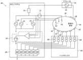
次に、図1に示されるシステムと共に使用するためのアブレーション及び有効現在位置(ACL)回路40の概略図である、図2を参照する。この構成は、参照により本明細書に援用される、Govariらによる米国特許出願公開第2006/0173251号及びOsadchyによる米国特許出願公開第2007/0038078号に記載されているものと同様である。構成は、本発明の原理に従って動作するように変更され得る。説明の便宜上、以下に簡潔に記載する。 Reference is now made to FIG. 2, which is a schematic diagram of an ablation and active current location (ACL) circuit 40 for use with the system shown in FIG. 1. This configuration is similar to that described in U.S. Patent Application Publication No. 2006/0173251 to Govari et al. and U.S. Patent Application Publication No. 2007/0038078 to Osadchy, both of which are incorporated herein by reference. The configuration may be modified to operate in accordance with the principles of the present invention. For ease of explanation, it is briefly described below.
接着皮膚用パッチであり得る、身体表面の複数の電極42は、被験者46の身体表面44(例えば、皮膚)に連結される。身体表面の電極42は、本明細書で「パッチ」と称されることがある。心臓用途では、身体表面の電極42は、通常、心臓を取り囲むように、3つが被験者の胸に、3つが背中に割り振られる。しかしながら、身体表面の電極42の数は重要ではなく、それらは医療処置部位付近全体の、身体表面44上の便利な位置に定置してよい。
A number of
通常、コンソール24(図1)内に配置される制御ユニット48は、電流測定回路50、及びそれぞれの動作周波数で1つ又は2つ以上の電極42を通して1つ又は2つ以上の身体表面の電極42に電流を駆動するための、1つ又は2つ以上のカテーテル電極伝送器52を含む。制御ユニット48は、位置決めプロセッサ(図1)に連結される。制御ユニット48は、少なくとも1つのアブレーション発生器56を備えるアブレータ54に連結される。身体表面の電極42及びアブレータ本体表面の電極58を通る電流は、アブレーション発生器56を有する回路内を流れ、本明細書では「パッチ測定回路」と称されることもある、身体電極受信器60内に配置されるそれぞれの電流測定回路によって測定される。身体電極受信器60は、通常、制御ユニット48に組み込まれる。代替的に、それらは、身体表面の電極42に貼り付けられてもよい。カテーテル電極は、測定電極62(円)及び二重目的用電極64(楕円)として表される。二重目的用電極64は、アブレーション電極として機能し、また測定電極の1つとしての役割も果たす。
A
身体表面の電極42は、アブレーション及び除細動電流からシステムを保護するパッチボックス66を介して身体電極受信器60に接続される。典型的には、システムは、6つの身体電極受信器60を備えて構成される。パッチボックスの寄生インピーダンス68(Z)は、製造中に測定されるため、事前に知られている。これらのインピーダンスについて以下で論じる。
The
典型的には、便宜上2つの測定電極62のみが示されているが、約80の測定電極がインピーダンス測定に用いられる。典型的には、1つ又は2つのアブレーション電極が存在する。身体内部のカテーテルの座標は、カテーテル上の電極と身体表面の電極42との間に電流を通すことにより、位置決めシステムで決定される。
Typically, about 80 measurement electrodes are used for impedance measurements, although only two
制御ユニット48はまた、アブレータ54有するアブレーション回路、及び二重目的用電極64を制御し得る。アブレータ54は、通常、制御ユニット48の外部に配置され、アブレーション発生器56を内蔵する。アブレーション発生器56は、アブレータ本体表面の電極58、及びこの例では制御ユニット48内に示される、アブレータフィルタ70と接続している。ただし、この位置は、必須ではない。スイッチ72は、以下に記載される様々な動作モードのためのアブレータ回路を構成する。電圧測定回路が、カテーテル電極伝送器52の出力を決定するために提供される。アブレーション回路は、カテーテル電極伝送器52のうちの1つに接続されていることが分かるであろう。
The
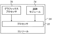
ここで図3を参照すると、同図は、本発明の実施形態によるプロセッサ22の態様のブロック図である。プロセッサ22は、コンソール24(図1)内に配置されるのが通例であるが、遠隔にある場合もあれば又は幾つかの場所に分散される場合もある。プロセッサ22は、追跡モジュール74のような追跡モジュールを用いて、上述の場所検知装置からの信号を、磁場生成コイル28(図1)により確定される3次元基準系内の位置座標に変換できる。プロセッサ22は、グラフィックスプロセッサ76に連結されている。グラフィックスプロセッサ76は、通例およそ2,000プロセッサを有する並列処理ユニットである。グラフィックスプロセッサ76の機能については、後述する。
Referring now to FIG. 3, there is shown a block diagram of aspects of the
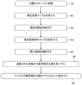
ここで図4を参照すると、同図は、本発明の一実施形態による、心臓の領域を介した電気的伝搬の最早期局所興奮到達時間(LAT)を特定するための方法のフローチャートである。プロセス工程は、表示の明瞭化のために、図4における特定の直線的シーケンス及び本明細書における他のフロー図に示される。しかしながら、かかる工程の多くは、並行して、非同期的に、又は異なる順序で行われてもよい点は明らかであろう。当業者であれば、プロセスを、例えば、状態図において、多数の相互に関連する状態又は事象としても代替的に表すことができることを理解するであろう。更に、例示されている工程段階の全てが、かかる方法の実施に必要とされるわけではない。 Reference is now made to FIG. 4, which is a flow chart of a method for identifying the earliest local activation time (LAT) of electrical propagation through a region of the heart, in accordance with one embodiment of the present invention. The process steps are shown in a particular linear sequence in FIG. 4, and in other flow diagrams herein, for clarity of presentation. However, it will be apparent that many of such steps may occur in parallel, asynchronously, or in a different order. Those skilled in the art will appreciate that a process may alternatively be represented as a number of interrelated states or events, for example, in a state diagram. Moreover, not all illustrated process steps are required to practice such a method.
最初の工程78において、心臓は、マルチ電極マッピングカテーテルにより、従来どおりにカテーテル処置される。Biosense Websterから入手可能な、PentaRay(登録商標)NAV又はNavistar(登録商標)Thermocool(登録商標)カテーテルなどのカテーテルは、最初の工程78に適している。カテーテルの電極は、一方の心房の各位置とガルバニック接触状態にある。
In a
工程80では、カテーテル内の電極の位置を決定する。判定を行う1つの方法は、現在位置マップ(CPM)の作成である。CPMは、電極(ある位置での電流を与える)と、ACL回路40(図2)と協働してその位置での磁気信号を与える磁気センサ(図示せず)とを備えたカテーテル14(図1)を用いて生成される。
At
次に、工程82で、基準座標系内でそれぞれ既知の位置を有するカテーテルの複数の電極と同時に、心房電気活動が記録される。可能であれば、最大-dV/dt偏差のような従来法を使用して、脱分極が最初に検出される。本願と同一譲受人に譲渡された、全体が参照により本明細書に援用される、米国特許第9,101,333号、同第9,629,567号、同第9,554,718号、及び米国特許出願第15/086,220号の教示を採用して、心房電気活動をより正確に識別及び記録することができる。心房LATの場合は、参照により本明細書に援用される、本願と同一譲受人に譲渡された米国特許第9,706,937号において教示された方法を使用して、心室遠距離場活動が除外され得る。
Next, at
次に、工程84で、プロセッサ22(図3)を用いて、注釈付き電気解剖学的マップを作成する。次いで、その開示内容が参照により本明細書に援用される米国特許第6,226,542号及び同第6,301,496号、並びに本願と同一譲受人に譲渡された米国特許第6,892,091号に開示されている方法に従って、機能の電気解剖学的マップ、例えば、電気的活性化マップを作成することができる。上述のCARTO 3システムは、カテーテル電極の読み取り値から、そのようなマップを生成することができる。
Next, at
次に、工程86において、工程84で作成された電気解剖学的マップ上の関心領域を選択する。これは、オペレータ16(図1)と対話的に行うことができる。あるいは、関心領域は、注釈の特性の分析に基づいて自動的に選択することができ、例えば、体表心電図におけるQRS群に対応する興奮時間間隔を有する領域、又は、複合細分化電位図(CFAE)を有する領域(参照により本明細書に援用される、本願と同一譲受人に譲渡された米国特許出願公開第2007/0197929号(Porathら)に説明されている)であり得る。
Next, in

次に、工程88において、プロセッサ22(図3)プロセッサは、選択された領域内で(マップ全体であってもよい)自動検査を実行する。リスト1中の擬似コードは、最早期注釈のセットを識別するための1つの方法を示す。
Next, in
次に最終工程90で、プロセッサは、最早期注釈セットの各要素について、マップ上にマークする。このセットは、1つ又は2つ以上の要素を有し得る。このセットのグラフィック表示は、オペレータ16にすぐに明らかになり、オペレータは次に、工程80で作成された現在位置マップを使用してカテーテルをナビゲートし、最早期注釈セットの1つ又は2つ以上の要素を含むより小さな領域で、より詳細なマッピングを行うことができる。
Then, in a
ここで図5を参照すると、同図は、本発明の一実施形態による、心室92のシミュレーション3次元表面である。図4に記載の手順に従ってマッピングが実施された。注釈は小円として示され、注釈94によって代表的に示される。領域96が自動検査のために選択され、同じLATを有する3つの最早期注釈の集合が、インジケータ98によってグラフィカルに示される。
Referring now to FIG. 5, this is a simulated 3D surface of a
当業者であれば、本発明が上記で具体的に図示及び記載されたものに限定されない点を理解するであろう。むしろ、本発明の範囲は、上述の様々な特徴の組み合わせ及び部分的組み合わせ、並びに上記の説明を読むことで当業者には想到されるであろう、先行技術にはない上述の特徴の変形例及び改変例をも含むものである。 Those skilled in the art will appreciate that the present invention is not limited to what has been specifically shown and described above. Rather, the scope of the present invention includes combinations and subcombinations of the various features described above, as well as variations and modifications of the above features that are not present in the prior art and that would occur to one of skill in the art upon reading the above description.
〔実施の態様〕
(1) 複数の電極を有するプローブを、生体被験者の心臓内に挿入する工程と、
該電極の現在位置マップを作成して、該電極のそれぞれの位置を確定する工程と、
該電極からの電位図を記録する工程と、
該電位図の分析により、該それぞれの位置で興奮時間に注釈を付ける工程と、
該興奮時間から、電気的伝播波の興奮マップを生成する工程と、
該興奮マップの領域を選択する工程と、
該選択された領域における該興奮時間の最早期のものを特定する工程と、
該興奮時間の該最早期のものをグラフィカルに示す工程と、
を含む、方法。
(2) 前記領域が、前記興奮マップ全体を含む、実施態様1に記載の方法。
(3) 前記興奮マップを生成する工程が、シミュレーション3次元表面として前記心臓をモデル化することを含む、実施態様1に記載の方法。
(4) 前記領域が、人間のオペレータにより選択される、実施態様1に記載の方法。
(5) 前記領域が自動的に選択される、実施態様1に記載の方法。
[Embodiment]
(1) inserting a probe having a plurality of electrodes into a heart of a living subject;
creating a current location map of the electrodes to determine the location of each of the electrodes;
recording an electrogram from the electrodes;
annotating activation times at each of said locations by analysis of said electrograms;
generating an excitation map of the electrical propagation wave from the excitation time;
selecting a region of the excitation map;
identifying the earliest of said excitation times in said selected regions;
graphically displaying the earliest of the excitation times;
A method comprising:
2. The method of claim 1, wherein the region comprises the entire excitation map.
3. The method of claim 1, wherein generating the excitation map comprises modeling the heart as a simulated three-dimensional surface.
4. The method of claim 1, wherein the region is selected by a human operator.
5. The method of claim 1, wherein the region is selected automatically.
(6) 複数の電極を有し、かつ生体被験者の心臓内への挿入に適合されたプローブと、
プロセッサであって、前記電極から電気信号を受信し、かつ
該電極の現在位置マップを作成して、該電極のそれぞれの位置を確定する工程と、
該電極からの電位図を記録する工程と、
該電位図の分析により、該それぞれの位置で興奮時間に注釈を付ける工程と、
該興奮時間から、電気的伝播波の興奮マップを生成する工程と、
該興奮マップの選択された領域において、該選択された領域における該興奮時間の最早期のものを自動的に特定する工程と、
該興奮時間の該最早期のものをグラフィカルに示す工程と、
を実行するよう構成されている、プロセッサと、
を含む、装置。
(7) 前記領域が、前記興奮マップ全体を含む、実施態様6に記載の装置。
(8) 前記興奮マップを生成する工程が、シミュレーション3次元表面として前記心臓をモデル化することを含む、実施態様6に記載の装置。
(9) コンピュータソフトウェア製品であって、コンピュータプログラム命令が記憶された非一時的なコンピュータ可読記憶媒体を含み、該命令は、コンピュータによって実行されるとき、該コンピュータに、
心臓内の複数の電極からの電気信号を受信する工程と、
該電極の現在位置マップを作成して、該電極のそれぞれの位置を確定する工程と、
該電極からの電位図を記録する工程と、
該電位図の分析により、該それぞれの位置で興奮時間に注釈を付ける工程と、
該興奮時間から、電気的伝播波の興奮マップを生成する工程と、
該興奮マップの領域を選択する工程と、
該選択された領域における該興奮時間の最早期のものを自動的に特定する工程と、
該興奮時間の該最早期のものをグラフィカルに示す工程と、
を実行させる、コンピュータソフトウェア製品。
(10) 前記領域が、前記興奮マップ全体を含む、実施態様9に記載のコンピュータソフトウェア製品。
(6) a probe having a plurality of electrodes and adapted for insertion into the heart of a living subject;
a processor for receiving electrical signals from the electrodes and creating a current position map of the electrodes to determine the position of each of the electrodes;
recording an electrogram from the electrodes;
annotating activation times at each of said locations by analysis of said electrograms;
generating an excitation map of the electrical propagation wave from the excitation time;
automatically identifying, in a selected region of the excitation map, an earliest of the excitation times in the selected region;
graphically displaying the earliest of the excitation times;
a processor configured to execute
13. An apparatus comprising:
7. The apparatus of claim 6, wherein the region comprises the entire excitation map.
8. The apparatus of claim 6, wherein generating the excitation map comprises modeling the heart as a simulated three-dimensional surface.
(9) A computer software product, comprising a non-transitory computer-readable storage medium having stored thereon computer program instructions which, when executed by a computer, cause the computer to:
receiving electrical signals from a plurality of electrodes within the heart;
creating a current location map of the electrodes to determine the location of each of the electrodes;
recording an electrogram from the electrodes;
annotating activation times at each of said locations by analysis of said electrograms;
generating an excitation map of the electrical propagation wave from the excitation time;
selecting a region of the excitation map;
automatically identifying the earliest of said excitation times in said selected regions;
graphically displaying the earliest of the excitation times;
A computer software product that allows
10. The computer software product of claim 9, wherein the region comprises the entire excitation map.
(11) 前記興奮マップを生成する工程が、シミュレーション3次元表面として前記心臓をモデル化することを含む、実施態様9に記載のコンピュータソフトウェア製品。
(12) 前記領域が、人間のオペレータにより選択される、実施態様9に記載のコンピュータソフトウェア製品。
(13) 前記プロセッサが、前記領域を自動的に選択するよう命令される、実施態様9に記載のコンピュータソフトウェア製品。
11. The computer software product of claim 9, wherein generating the excitation map comprises modeling the heart as a simulated three-dimensional surface.
12. The computer software product of claim 9, wherein the region is selected by a human operator.
13. The computer software product of claim 9, wherein the processor is instructed to automatically select the region.
Claims (4)
1つ又は2つ以上の体表面電極と、
プロセッサであって、前記複数の電極から電気信号を受信し、かつ
前記複数の電極の現在位置マップを作成して、前記複数の電極のそれぞれの位置を確定する工程と、
前記複数の電極からの電位図を記録する工程と、
該電位図の分析により、該それぞれの位置で興奮時間に注釈を付ける工程と、
該興奮時間から、電気的伝播波の興奮マップを生成する工程と、
該興奮マップの選択された領域において、該選択された領域における該興奮時間の最早期のものを自動的に特定する工程と、
該興奮時間の該最早期のものをグラフィカルに示す工程と、
該興奮マップにおける、1の興奮時間から次の興奮時間までの時間間隔が、前記1つ又は2つ以上の体表面電極から取得された体表心電図における1のQRS群から次のQRS群までの時間間隔と等しい領域を、該選択された領域として自動的に特定する工程と、
を実行するよう構成されている、プロセッサと、を含む、
装置。 a probe having a plurality of electrodes and adapted for insertion into the heart of a living subject;
one or more body surface electrodes;
a processor that receives electrical signals from the plurality of electrodes; and
creating a current location map of the plurality of electrodes to determine the location of each of the plurality of electrodes;
recording electrograms from the plurality of electrodes;
annotating activation times at each of said locations by analysis of said electrograms;
generating an excitation map of the electrical propagation wave from the excitation time;
automatically identifying, in a selected region of the excitation map, an earliest of the excitation times in the selected region;
graphically displaying the earliest of the excitation times;
automatically identifying a region in the excitation map in which a time interval from one excitation time to a next excitation time is equal to a time interval from one QRS complex to a next QRS complex in a surface electrocardiogram acquired from the one or more body surface electrodes as the selected region;
and a processor configured to execute
Device.
心臓内の複数の電極からの電気信号を受信する工程と、
体表面電極から体表心電図を受信する工程と、
前記複数の電極の現在位置マップを作成して、前記複数の電極のそれぞれの位置を確定する工程と、
前記複数の電極からの電位図を記録する工程と、
該電位図の分析により、該それぞれの位置で興奮時間に注釈を付ける工程と、
該興奮時間から、電気的伝播波の興奮マップを生成する工程と、
該興奮マップの領域を選択する工程と、
該選択された領域における該興奮時間の最早期のものを自動的に特定する工程と、
該興奮時間の該最早期のものをグラフィカルに示す工程と、
該興奮マップにおける、1の興奮時間から次の興奮時間までの時間間隔が、前記体表心電図における1のQRS群から次のQRS群までの時間間隔と等しい領域を、該選択された領域として自動的に特定する工程と、
を実行させる、コンピュータプログラム。 A computer program, which when executed by a computer, causes the computer to:
receiving electrical signals from a plurality of electrodes within the heart;
receiving a surface electrocardiogram from body surface electrodes;
creating a current location map of the plurality of electrodes to determine the location of each of the plurality of electrodes;
recording electrograms from the plurality of electrodes;
annotating activation times at each of said locations by analysis of said electrograms;
generating an excitation map of the electrical propagation wave from the excitation time;
selecting a region of the excitation map;
automatically identifying the earliest of said excitation times in said selected regions;
graphically displaying the earliest of the excitation times;
automatically identifying as the selected region a region in the excitation map in which the time interval from one excitation time to the next excitation time is equal to the time interval from one QRS complex to the next QRS complex in the surface electrocardiogram;
A computer program that executes the following:
Applications Claiming Priority (3)
| Application Number | Priority Date | Filing Date | Title |
|---|---|---|---|
| US15/702,340 | 2017-09-12 | ||
| US15/702,340 US10441188B2 (en) | 2017-09-12 | 2017-09-12 | Automatic display of earliest LAT point |
| JP2018169485A JP2019051309A (en) | 2017-09-12 | 2018-09-11 | Automatic display of earliest lat point |
Related Parent Applications (1)
| Application Number | Title | Priority Date | Filing Date |
|---|---|---|---|
| JP2018169485A Division JP2019051309A (en) | 2017-09-12 | 2018-09-11 | Automatic display of earliest lat point |
Publications (2)
| Publication Number | Publication Date |
|---|---|
| JP2023144056A JP2023144056A (en) | 2023-10-06 |
| JP7622162B2 true JP7622162B2 (en) | 2025-01-27 |
Family
ID=63685571
Family Applications (2)
| Application Number | Title | Priority Date | Filing Date |
|---|---|---|---|
| JP2018169485A Pending JP2019051309A (en) | 2017-09-12 | 2018-09-11 | Automatic display of earliest lat point |
| JP2023132565A Active JP7622162B2 (en) | 2017-09-12 | 2023-08-16 | Automatic display of the earliest LAT |
Family Applications Before (1)
| Application Number | Title | Priority Date | Filing Date |
|---|---|---|---|
| JP2018169485A Pending JP2019051309A (en) | 2017-09-12 | 2018-09-11 | Automatic display of earliest lat point |
Country Status (7)
| Country | Link |
|---|---|
| US (1) | US10441188B2 (en) |
| EP (1) | EP3453323A1 (en) |
| JP (2) | JP2019051309A (en) |
| CN (1) | CN109480821A (en) |
| AU (1) | AU2018220133A1 (en) |
| CA (1) | CA3017171A1 (en) |
| IL (1) | IL261387B (en) |
Families Citing this family (41)
| Publication number | Priority date | Publication date | Assignee | Title |
|---|---|---|---|---|
| US10905329B2 (en) | 2016-06-09 | 2021-02-02 | Biosense Webster (Israel) Ltd. | Multi-function conducting elements for a catheter |
| US12029545B2 (en) | 2017-05-30 | 2024-07-09 | Biosense Webster (Israel) Ltd. | Catheter splines as location sensors |
| US20190314083A1 (en) | 2018-04-11 | 2019-10-17 | Biosense Webster (Israel) Ltd. | Flexible Multi-Arm Catheter with Diametrically Opposed Sensing Electrodes |
| US11045628B2 (en) | 2018-12-11 | 2021-06-29 | Biosense Webster (Israel) Ltd. | Balloon catheter with high articulation |
| US11207016B2 (en) | 2018-12-28 | 2021-12-28 | Biosense Webster (Israel) Ltd. | Mapping ECG signals using a multipole electrode assembly |
| US11850051B2 (en) | 2019-04-30 | 2023-12-26 | Biosense Webster (Israel) Ltd. | Mapping grid with high density electrode array |
| US11712172B2 (en) * | 2019-07-18 | 2023-08-01 | Biosense Webster (Israel) Ltd. | Visual guidance for positioning a distal end of a medical probe |
| US11452485B2 (en) | 2019-08-05 | 2022-09-27 | Biosense Webster (Israel) Ltd. | Electroanatomical map re-annotation |
| US11759150B2 (en) | 2019-08-27 | 2023-09-19 | Biosense Webster (Israel) Ltd. | Accurate basket catheter tracking |
| US12285258B2 (en) * | 2019-09-24 | 2025-04-29 | Biosense Webster (Israel) Ltd. | 3D intracardiac activity presentation |
| US11633229B2 (en) * | 2019-10-07 | 2023-04-25 | Biosense Webster (Israel) Ltd. | 3D electrical activity representation |
| GB201915680D0 (en) * | 2019-10-29 | 2019-12-11 | Rhythm A1 Ltd | Method and system for aiding mapping heart rhythm abnormalities |
| US11950930B2 (en) | 2019-12-12 | 2024-04-09 | Biosense Webster (Israel) Ltd. | Multi-dimensional acquisition of bipolar signals from a catheter |
| US11517218B2 (en) | 2019-12-20 | 2022-12-06 | Biosense Webster (Israel) Ltd. | Selective graphical presentation of electrophysiological parameters |
| US20210369132A1 (en) | 2020-05-29 | 2021-12-02 | Biosense Webster (Israel) Ltd. | Intraluminal reference electrode for cardiovascular treatment apparatus |
| US11987017B2 (en) | 2020-06-08 | 2024-05-21 | Biosense Webster (Israel) Ltd. | Features to assist in assembly and testing of devices |
| US11730413B2 (en) | 2020-07-01 | 2023-08-22 | Biosense Webster (Israel) Ltd. | Analyzing multi-electrode catheter signals to determine electrophysiological (EP) wave propagation vector |
| US12303281B2 (en) | 2020-07-01 | 2025-05-20 | Biosense Webster (Israel) Ltd. | Mapping resolution of electrophysiological (EP) wave propagating on the surface of patient heart |
| US12048479B2 (en) | 2020-09-10 | 2024-07-30 | Biosense Webster (Israel) Ltd. | Surface mounted electrode catheter |
| US11950841B2 (en) | 2020-09-22 | 2024-04-09 | Biosense Webster (Israel) Ltd. | Basket catheter having insulated ablation electrodes and diagnostic electrodes |
| US11950840B2 (en) | 2020-09-22 | 2024-04-09 | Biosense Webster (Israel) Ltd. | Basket catheter having insulated ablation electrodes |
| US12082875B2 (en) | 2020-09-24 | 2024-09-10 | Biosense Webster (Israel) Ltd | Balloon catheter having a coil for sensing tissue temperature and position of the balloon |
| US11974803B2 (en) | 2020-10-12 | 2024-05-07 | Biosense Webster (Israel) Ltd. | Basket catheter with balloon |
| US12201786B2 (en) | 2020-12-17 | 2025-01-21 | Biosense Webster (Israel) Ltd. | Measurement of distal end dimension of catheters using magnetic fields |
| US11918383B2 (en) | 2020-12-21 | 2024-03-05 | Biosense Webster (Israel) Ltd. | Visualizing performance of catheter electrodes |
| US11478182B2 (en) * | 2021-01-07 | 2022-10-25 | Biosense Webster (Israel) Ltd. | Incorporating a confidence level into an electrophysiological (EP) map |
| US12064170B2 (en) | 2021-05-13 | 2024-08-20 | Biosense Webster (Israel) Ltd. | Distal assembly for catheter with lumens running along spines |
| US20220395214A1 (en) * | 2021-06-09 | 2022-12-15 | Biosense Webster (Israel) Ltd. | Wave propagation control enhancement |
| IL293942B2 (en) * | 2021-06-22 | 2025-07-01 | Biosense Webster Israel Ltd | Improving resolution in mapping an electrophysiological (EP) wave propagating across the surface of a patient's heart |
| US12364426B2 (en) | 2021-08-12 | 2025-07-22 | Biosense Webster (Israel) Ltd. | Electro-anatomical mapping and annotation presented in electrophysiological procedures |
| US12004804B2 (en) | 2021-09-09 | 2024-06-11 | Biosense Webster (Israel) Ltd. | Basket catheter with mushroom shape distal tip |
| US12478424B2 (en) | 2021-09-10 | 2025-11-25 | Biosense Webster (Israel) Ltd. | Staggered pairs of biased ablation electrodes on basket catheter |
| US12011280B2 (en) | 2021-10-04 | 2024-06-18 | Biosense Webster (Israel) Ltd. | Electrophysiological mapping in the presence of injury current |
| US12533489B2 (en) | 2021-10-08 | 2026-01-27 | Biosense Webster (Israel) Ltd. | Measuring tissue proximity for multi-electrode catheter |
| US12419683B2 (en) | 2021-12-22 | 2025-09-23 | Biosense Webster (Israel) Ltd. | Irreversible electroporation with shorted electrodes |
| US12446946B2 (en) | 2022-01-20 | 2025-10-21 | Biosense Webster (Israel) Ltd. | Systems and methods for a single spiral electrode assembly forming a spherical basket for improved tissue contact and current delivery |
| US12484961B2 (en) | 2022-01-20 | 2025-12-02 | Biosense Webster (Israel) Ltd. | Mechanical retainer systems for electrodes of a basket catheter, and methods of the same |
| US12440263B2 (en) | 2022-01-20 | 2025-10-14 | Biosense Webster (Israel) Ltd. | Systems and methods for tripodic spines forming a spherical basket for improved tissue contact and current delivery |
| US12471989B2 (en) | 2022-04-28 | 2025-11-18 | Biosense Webster (Israel) Ltd. | Strengthened expandable baskets for medical probes and medical probes containing strengthen expandable baskets |
| US12533185B2 (en) | 2022-12-28 | 2026-01-27 | Biosense Webster (Israel) Ltd. | Basket end effector with distal position sensor |
| US12521035B2 (en) | 2022-12-29 | 2026-01-13 | Biosense Webster (Israel) Ltd. | Cylindrical cage systems and methods for distributed tissue contact for mapping and ablation |
Citations (4)
| Publication number | Priority date | Publication date | Assignee | Title |
|---|---|---|---|---|
| JP2014503319A (en) | 2011-01-13 | 2014-02-13 | リズミア メディカル インコーポレイテッド | Beat adjustment and selection for cardiac mapping |
| US20140243641A1 (en) | 2012-08-27 | 2014-08-28 | Birinder Robert Boveja | Methods and system for real-time cardiac mapping |
| JP2015054250A (en) | 2013-09-12 | 2015-03-23 | バイオセンス・ウエブスター・(イスラエル)・リミテッドBiosense Webster (Israel), Ltd. | Methods for mapping ventricular / atrial premature contractions during sinus rhythm |
| JP2016202910A (en) | 2015-04-22 | 2016-12-08 | バイオセンス・ウエブスター・(イスラエル)・リミテッドBiosense Webster (Israel), Ltd. | Ventricular electrical activity indicator |
Family Cites Families (37)
| Publication number | Priority date | Publication date | Assignee | Title |
|---|---|---|---|---|
| US6522905B2 (en) * | 1993-03-11 | 2003-02-18 | Jawahar M. Desai | Apparatus and method for cardiac ablation |
| US5738096A (en) | 1993-07-20 | 1998-04-14 | Biosense, Inc. | Cardiac electromechanics |
| US6490474B1 (en) * | 1997-08-01 | 2002-12-03 | Cardiac Pathways Corporation | System and method for electrode localization using ultrasound |
| US6226542B1 (en) * | 1998-07-24 | 2001-05-01 | Biosense, Inc. | Three-dimensional reconstruction of intrabody organs |
| US6301496B1 (en) * | 1998-07-24 | 2001-10-09 | Biosense, Inc. | Vector mapping of three-dimensionally reconstructed intrabody organs and method of display |
| US6236883B1 (en) * | 1999-02-03 | 2001-05-22 | The Trustees Of Columbia University In The City Of New York | Methods and systems for localizing reentrant circuits from electrogram features |
| US6892091B1 (en) | 2000-02-18 | 2005-05-10 | Biosense, Inc. | Catheter, method and apparatus for generating an electrical map of a chamber of the heart |
| US6814733B2 (en) | 2002-01-31 | 2004-11-09 | Biosense, Inc. | Radio frequency pulmonary vein isolation |
| US6997924B2 (en) | 2002-09-17 | 2006-02-14 | Biosense Inc. | Laser pulmonary vein isolation |
| US7156816B2 (en) | 2002-11-26 | 2007-01-02 | Biosense, Inc. | Ultrasound pulmonary vein isolation |
| US20050209524A1 (en) * | 2004-03-10 | 2005-09-22 | General Electric Company | System and method for receiving and storing information pertaining to a patient |
| JP2008523929A (en) * | 2004-12-21 | 2008-07-10 | シドニー ウエスト エリア ヘルス サービス | Automatic processing of electrophysiological data |
| US7869865B2 (en) | 2005-01-07 | 2011-01-11 | Biosense Webster, Inc. | Current-based position sensing |
| US7848787B2 (en) | 2005-07-08 | 2010-12-07 | Biosense Webster, Inc. | Relative impedance measurement |
| US7536218B2 (en) | 2005-07-15 | 2009-05-19 | Biosense Webster, Inc. | Hybrid magnetic-based and impedance-based position sensing |
| US7756576B2 (en) | 2005-08-26 | 2010-07-13 | Biosense Webster, Inc. | Position sensing and detection of skin impedance |
| US9629567B2 (en) | 2006-01-12 | 2017-04-25 | Biosense Webster, Inc. | Mapping of complex fractionated atrial electrogram |
| WO2008138009A1 (en) * | 2007-05-08 | 2008-11-13 | C.R. Bard, Inc. | Rapid 3d mapping using multielectrode position data |
| EP2348979B1 (en) * | 2008-11-07 | 2019-10-30 | Cardioinsight Technologies, Inc. | Visualization of physiological data for virtual electrodes |
| EP2345024B1 (en) * | 2008-11-10 | 2017-11-08 | Cardioinsight Technologies, Inc. | Visualization of electrophysiology data |
| BR112012025468A2 (en) * | 2010-04-08 | 2019-09-24 | The Regents Of The University Of California | system for reconstructing heart signals associated with a complex rhythm disorder received through a plurality of patient's heart channels, assembly for reconstructing heart signals associated with a complex rhythm disorder received through a plurality of patient's heart channels and method of reconstructing cardiac signals associated with a complex rhythm disorder received through a plurality of channels in a patient's heart |
| US9271680B2 (en) * | 2010-09-17 | 2016-03-01 | Cardioinsight Technologies, Inc. | System and methods for computing activation maps |
| US8478383B2 (en) | 2010-12-14 | 2013-07-02 | Biosense Webster (Israel), Ltd. | Probe tracking using multiple tracking methods |
| CA2835001A1 (en) * | 2011-05-02 | 2012-11-08 | Topera, Inc. | System and method for targeting heart rhythm disorders using shaped ablation |
| CA2841388A1 (en) * | 2011-07-05 | 2013-01-10 | Cardioinsight Technologies, Inc. | Localization for electrocardiographic mapping |
| US9101333B2 (en) | 2011-11-14 | 2015-08-11 | Biosense Webster (Israel) Ltd. | Integrative atrial fibrillation ablation |
| US9144391B2 (en) * | 2013-05-16 | 2015-09-29 | Boston Scientific Scimed Inc. | Enhanced activation onset time optimization by similarity based pattern matching |
| US9554718B2 (en) | 2014-01-29 | 2017-01-31 | Biosense Webster (Israel) Ltd. | Double bipolar configuration for atrial fibrillation annotation |
| EP3113671B1 (en) * | 2014-03-07 | 2023-10-25 | Boston Scientific Scimed, Inc. | Medical devices for mapping cardiac tissue |
| US10582894B2 (en) * | 2016-01-14 | 2020-03-10 | Biosense Webster (Israel) Ltd. | Region of interest rotational activity pattern detection |
| US10624554B2 (en) * | 2016-01-14 | 2020-04-21 | Biosense Webster (Israel) Ltd. | Non-overlapping loop-type or spline-type catheter to determine activation source direction and activation source type |
| US10517496B2 (en) * | 2016-01-14 | 2019-12-31 | Biosense Webster (Israel) Ltd. | Region of interest focal source detection |
| US11006887B2 (en) * | 2016-01-14 | 2021-05-18 | Biosense Webster (Israel) Ltd. | Region of interest focal source detection using comparisons of R-S wave magnitudes and LATs of RS complexes |
| US10282888B2 (en) | 2016-01-28 | 2019-05-07 | Biosense Webster (Israel) Ltd. | High definition coloring of heart chambers |
| US11219769B2 (en) * | 2016-02-26 | 2022-01-11 | Medtronic, Inc. | Noninvasive methods and systems of determining the extent of tissue capture from cardiac pacing |
| US10357168B2 (en) * | 2016-03-07 | 2019-07-23 | Apn Health, Llc | Time transformation of local activation times |
| US11129574B2 (en) | 2016-12-12 | 2021-09-28 | Biosense Webster (Israel) Ltd. | Real time electroanatomical coloring of the heart |
-
2017
- 2017-09-12 US US15/702,340 patent/US10441188B2/en active Active
-
2018
- 2018-08-24 AU AU2018220133A patent/AU2018220133A1/en not_active Abandoned
- 2018-08-27 IL IL261387A patent/IL261387B/en unknown
- 2018-09-11 EP EP18193757.4A patent/EP3453323A1/en not_active Ceased
- 2018-09-11 JP JP2018169485A patent/JP2019051309A/en active Pending
- 2018-09-11 CA CA3017171A patent/CA3017171A1/en not_active Abandoned
- 2018-09-12 CN CN201811061500.0A patent/CN109480821A/en active Pending
-
2023
- 2023-08-16 JP JP2023132565A patent/JP7622162B2/en active Active
Patent Citations (4)
| Publication number | Priority date | Publication date | Assignee | Title |
|---|---|---|---|---|
| JP2014503319A (en) | 2011-01-13 | 2014-02-13 | リズミア メディカル インコーポレイテッド | Beat adjustment and selection for cardiac mapping |
| US20140243641A1 (en) | 2012-08-27 | 2014-08-28 | Birinder Robert Boveja | Methods and system for real-time cardiac mapping |
| JP2015054250A (en) | 2013-09-12 | 2015-03-23 | バイオセンス・ウエブスター・(イスラエル)・リミテッドBiosense Webster (Israel), Ltd. | Methods for mapping ventricular / atrial premature contractions during sinus rhythm |
| JP2016202910A (en) | 2015-04-22 | 2016-12-08 | バイオセンス・ウエブスター・(イスラエル)・リミテッドBiosense Webster (Israel), Ltd. | Ventricular electrical activity indicator |
Also Published As
| Publication number | Publication date |
|---|---|
| CA3017171A1 (en) | 2019-03-12 |
| US20190076045A1 (en) | 2019-03-14 |
| JP2019051309A (en) | 2019-04-04 |
| AU2018220133A1 (en) | 2019-03-28 |
| EP3453323A1 (en) | 2019-03-13 |
| IL261387B (en) | 2021-07-29 |
| IL261387A (en) | 2019-02-28 |
| JP2023144056A (en) | 2023-10-06 |
| CN109480821A (en) | 2019-03-19 |
| US10441188B2 (en) | 2019-10-15 |
Similar Documents
| Publication | Publication Date | Title |
|---|---|---|
| JP7622162B2 (en) | Automatic display of the earliest LAT | |
| JP7047016B2 (en) | Alignment map using intracardiac signal | |
| JP7023693B2 (en) | A device that displays electrical anatomical information about the heart | |
| US9883918B2 (en) | Method for mapping ventricular/atrial premature beats during sinus rhythm | |
| CN102131458B (en) | Sensing apparatus for sensing an object | |
| JP2018149271A (en) | Methods and systems for eliminating various heart diseases by analyzing intracardiac signals, providing detailed maps, and determining potential ablation points | |
| JP7536473B2 (en) | Midfield Signal Extraction | |
| CN103565432A (en) | Graphic interface for multi-spine probe | |
| JP2016116858A (en) | Far field-insensitive intracardiac catheter electrodes | |
| EP4122413A1 (en) | Accurate tissue proximity | |
| US20200397329A1 (en) | Methods and systems for transmural tissue mapping | |
| Scinicariello et al. | Cardiac Mapping Technologies | |
| Mattison et al. | Cardiac Mapping Technologies |
Legal Events
| Date | Code | Title | Description |
|---|---|---|---|
| A621 | Written request for application examination |
Free format text: JAPANESE INTERMEDIATE CODE: A621 Effective date: 20230816 |
|
| A977 | Report on retrieval |
Free format text: JAPANESE INTERMEDIATE CODE: A971007 Effective date: 20240611 |
|
| A131 | Notification of reasons for refusal |
Free format text: JAPANESE INTERMEDIATE CODE: A131 Effective date: 20240723 |
|
| A521 | Request for written amendment filed |
Free format text: JAPANESE INTERMEDIATE CODE: A523 Effective date: 20241023 |
|
| TRDD | Decision of grant or rejection written | ||
| A01 | Written decision to grant a patent or to grant a registration (utility model) |
Free format text: JAPANESE INTERMEDIATE CODE: A01 Effective date: 20241217 |
|
| A61 | First payment of annual fees (during grant procedure) |
Free format text: JAPANESE INTERMEDIATE CODE: A61 Effective date: 20250115 |
|
| R150 | Certificate of patent or registration of utility model |
Ref document number: 7622162 Country of ref document: JP Free format text: JAPANESE INTERMEDIATE CODE: R150 |