JP6701365B2 - Surgical instrument - Google Patents
Surgical instrument Download PDFInfo
- Publication number
- JP6701365B2 JP6701365B2 JP2018543559A JP2018543559A JP6701365B2 JP 6701365 B2 JP6701365 B2 JP 6701365B2 JP 2018543559 A JP2018543559 A JP 2018543559A JP 2018543559 A JP2018543559 A JP 2018543559A JP 6701365 B2 JP6701365 B2 JP 6701365B2
- Authority
- JP
- Japan
- Prior art keywords
- axis
- rotor
- respect
- rotation
- shaft
- Prior art date
- Legal status (The legal status is an assumption and is not a legal conclusion. Google has not performed a legal analysis and makes no representation as to the accuracy of the status listed.)
- Expired - Fee Related
Links
Images


Classifications
-
- A—HUMAN NECESSITIES
- A61—MEDICAL OR VETERINARY SCIENCE; HYGIENE
- A61B—DIAGNOSIS; SURGERY; IDENTIFICATION
- A61B17/00—Surgical instruments, devices or methods
- A61B17/28—Surgical forceps
- A61B17/29—Forceps for use in minimally invasive surgery
-
- A—HUMAN NECESSITIES
- A61—MEDICAL OR VETERINARY SCIENCE; HYGIENE
- A61B—DIAGNOSIS; SURGERY; IDENTIFICATION
- A61B18/00—Surgical instruments, devices or methods for transferring non-mechanical forms of energy to or from the body
- A61B18/04—Surgical instruments, devices or methods for transferring non-mechanical forms of energy to or from the body by heating
- A61B18/12—Surgical instruments, devices or methods for transferring non-mechanical forms of energy to or from the body by heating by passing a current through the tissue to be heated, e.g. high-frequency current
- A61B18/14—Probes or electrodes therefor
- A61B18/1442—Probes having pivoting end effectors, e.g. forceps
- A61B18/1445—Probes having pivoting end effectors, e.g. forceps at the distal end of a shaft, e.g. forceps or scissors at the end of a rigid rod
-
- A—HUMAN NECESSITIES
- A61—MEDICAL OR VETERINARY SCIENCE; HYGIENE
- A61B—DIAGNOSIS; SURGERY; IDENTIFICATION
- A61B17/00—Surgical instruments, devices or methods
- A61B17/00234—Surgical instruments, devices or methods for minimally invasive surgery
- A61B2017/00292—Surgical instruments, devices or methods for minimally invasive surgery mounted on or guided by flexible, e.g. catheter-like, means
- A61B2017/003—Steerable
- A61B2017/00318—Steering mechanisms
- A61B2017/00323—Cables or rods
- A61B2017/00327—Cables or rods with actuating members moving in opposite directions
-
- A—HUMAN NECESSITIES
- A61—MEDICAL OR VETERINARY SCIENCE; HYGIENE
- A61B—DIAGNOSIS; SURGERY; IDENTIFICATION
- A61B17/00—Surgical instruments, devices or methods
- A61B2017/00367—Details of actuation of instruments, e.g. relations between pushing buttons, or the like, and activation of the tool, working tip, or the like
- A61B2017/00398—Details of actuation of instruments, e.g. relations between pushing buttons, or the like, and activation of the tool, working tip, or the like using powered actuators, e.g. stepper motors, solenoids
-
- A—HUMAN NECESSITIES
- A61—MEDICAL OR VETERINARY SCIENCE; HYGIENE
- A61B—DIAGNOSIS; SURGERY; IDENTIFICATION
- A61B17/00—Surgical instruments, devices or methods
- A61B2017/00477—Coupling
-
- A—HUMAN NECESSITIES
- A61—MEDICAL OR VETERINARY SCIENCE; HYGIENE
- A61B—DIAGNOSIS; SURGERY; IDENTIFICATION
- A61B17/00—Surgical instruments, devices or methods
- A61B17/28—Surgical forceps
- A61B17/29—Forceps for use in minimally invasive surgery
- A61B2017/2901—Details of shaft
- A61B2017/2902—Details of shaft characterized by features of the actuating rod
- A61B2017/2903—Details of shaft characterized by features of the actuating rod transferring rotary motion
-
- A—HUMAN NECESSITIES
- A61—MEDICAL OR VETERINARY SCIENCE; HYGIENE
- A61B—DIAGNOSIS; SURGERY; IDENTIFICATION
- A61B17/00—Surgical instruments, devices or methods
- A61B17/28—Surgical forceps
- A61B17/29—Forceps for use in minimally invasive surgery
- A61B2017/2901—Details of shaft
- A61B2017/2905—Details of shaft flexible
-
- A—HUMAN NECESSITIES
- A61—MEDICAL OR VETERINARY SCIENCE; HYGIENE
- A61B—DIAGNOSIS; SURGERY; IDENTIFICATION
- A61B17/00—Surgical instruments, devices or methods
- A61B17/28—Surgical forceps
- A61B17/29—Forceps for use in minimally invasive surgery
- A61B2017/2926—Details of heads or jaws
- A61B2017/2927—Details of heads or jaws the angular position of the head being adjustable with respect to the shaft
- A61B2017/2929—Details of heads or jaws the angular position of the head being adjustable with respect to the shaft with a head rotatable about the longitudinal axis of the shaft
- A61B2017/293—Details of heads or jaws the angular position of the head being adjustable with respect to the shaft with a head rotatable about the longitudinal axis of the shaft with means preventing relative rotation between the shaft and the actuating rod
-
- A—HUMAN NECESSITIES
- A61—MEDICAL OR VETERINARY SCIENCE; HYGIENE
- A61B—DIAGNOSIS; SURGERY; IDENTIFICATION
- A61B18/00—Surgical instruments, devices or methods for transferring non-mechanical forms of energy to or from the body
- A61B2018/00053—Mechanical features of the instrument of device
- A61B2018/00184—Moving parts
- A61B2018/00202—Moving parts rotating
- A61B2018/00208—Moving parts rotating actively driven, e.g. by a motor
Landscapes
- Health & Medical Sciences (AREA)
- Surgery (AREA)
- Life Sciences & Earth Sciences (AREA)
- Engineering & Computer Science (AREA)
- Biomedical Technology (AREA)
- Public Health (AREA)
- Nuclear Medicine, Radiotherapy & Molecular Imaging (AREA)
- Veterinary Medicine (AREA)
- General Health & Medical Sciences (AREA)
- Heart & Thoracic Surgery (AREA)
- Medical Informatics (AREA)
- Molecular Biology (AREA)
- Animal Behavior & Ethology (AREA)
- Physics & Mathematics (AREA)
- Otolaryngology (AREA)
- Plasma & Fusion (AREA)
- Ophthalmology & Optometry (AREA)
- Surgical Instruments (AREA)
Description
本発明は、処置対象を処置するエンドエフェクタがシャフトに対して屈曲動作を行う外科処置具に関する。 The present invention relates to a surgical treatment tool in which an end effector that treats a treatment target bends with respect to a shaft.
米国特許出願公開第2015/0066022号明細書には、保持可能なハウジングに、シャフトが長手軸を中心に回転可能に取付けられる外科処置具が開示されている。この外科処置具では、シャフトに設けられる回転操作ノブ(操作部材)での操作入力によって、シャフト及びエンドエフェクタが長手軸を中心としてハウジングに対して回転する。また、この外科処置具では、エンドエフェクタはシャフトに対して屈曲可能であり、エンドエフェクタの屈曲動作によって、エンドエフェクタのシャフト(長手軸)に対する角度が変化する。そして、エンドエフェクタを屈曲動作させる操作入力が行われる操作部材として、屈曲操作ダイヤルがハウジングに取付けられている。 U.S. Patent Application Publication No. 2015/0066022 discloses a surgical instrument in which a shaft is rotatably mounted on a retainable housing about a longitudinal axis. In this surgical instrument, the shaft and the end effector rotate about the longitudinal axis with respect to the housing by an operation input from a rotation operation knob (operation member) provided on the shaft. Further, in this surgical treatment tool, the end effector can be bent with respect to the shaft, and the bending operation of the end effector changes the angle of the end effector with respect to the shaft (longitudinal axis). A bending operation dial is attached to the housing as an operation member that receives an operation input for bending the end effector.
米国特許出願公開第2015/0066022号明細書では、屈曲操作ダイヤルは回転操作ノブ(シャフト)から独立して回転し、回転操作ノブを長手軸の軸回りに回転させても、屈曲操作ダイヤルは、シャフト及びエンドエフェクタと一緒に回転しない。このため、回転操作ノブでの操作入力によってエンドエフェクタの長手軸の軸回りについての角度位置が変化することにより、エンドエフェクタの屈曲方向と屈曲操作ダイヤルでの操作方向(回転方向)との相対関係が変化する。したがって、術者は、エンドエフェクタの屈曲方向を把握し難くなり、エンドエフェクタを屈曲動作させる操作の操作性が低下してしまう。 In US Patent Application Publication No. 2015/0066022, the bending operation dial rotates independently of the rotation operation knob (shaft), and even when the rotation operation knob is rotated around the axis of the longitudinal axis, the bending operation dial is Does not rotate with shaft and end effector. Therefore, the angular position about the axis of the longitudinal axis of the end effector changes due to the operation input with the rotary operation knob, so that the relative relationship between the bending direction of the end effector and the operation direction (rotational direction) of the bending operation dial. Changes. Therefore, it becomes difficult for the operator to grasp the bending direction of the end effector, and the operability of the operation of bending the end effector is deteriorated.
本発明は前記課題に着目してなされたものであり、その目的とするところは、エンドエフェクタの長手軸の軸回りについての角度位置に関係なく、エンドエフェクタをシャフトに対して屈曲動作させる操作の操作性が確保される外科処置具を提供することにある。 The present invention has been made in view of the above problems, and an object of the present invention is to perform a bending operation of an end effector with respect to a shaft regardless of an angular position about an axis of a longitudinal axis of the end effector. It is to provide a surgical treatment tool that ensures operability.
前記目的を達成するために、本発明のある態様の外科処置具は、長手軸を規定し、基端側から先端側へ前記長手軸に沿って延設される長尺部材と、前記長尺部材が先端側に連結されるハウジングと、前記長尺部材の先端側に取付けられ、前記長尺部材に対して曲がるエンドエフェクタと、前記長尺部材及び前記エンドエフェクタを前記長手軸の軸回りに前記ハウジングに対して回転させる操作入力が行われる第1の操作部材と、前記ハウジングに取付けられ、前記エンドエフェクタを前記長尺部材に対して曲げる操作入力が行われる第2の操作部材と、前記ハウジングの内部に設けられ、前記長手軸と平行な回転軸を有し、前記第2の操作部材での操作入力により前記回転軸の軸回りに回転する回転子と、前記回転子及び前記エンドエフェクタに接続され、前記第2の操作部材での前記操作入力に基づいて前記回転子が前記回転軸の前記軸回りに回転運動することにより、前記エンドエフェクタを曲げる駆動力を前記エンドエフェクタに伝達する伝達部材と、を備え、前記第2の操作部材、前記回転子及び前記伝達部材は、前記第1の操作部材での前記操作入力により、前記長尺部材及び前記エンドエフェクタと一緒に前記長手軸の前記軸回りに前記ハウジングに対して回転する。
前記目的を達成するために、本発明のある態様の外科処置具は、長手軸を規定し、基端側から先端側へ前記長手軸に沿って延設される長尺部材と、前記長尺部材が先端側に連結されるハウジングと、前記長尺部材の先端側に取付けられ、前記長尺部材に対して曲がるエンドエフェクタと、前記長尺部材及び前記エンドエフェクタを前記長手軸の軸回りに前記ハウジングに対して回転させる操作入力が行われる第1の操作部材と、前記ハウジングに取付けられ、前記エンドエフェクタを前記長尺部材に対して曲げる操作入力が行われる第2の操作部材と、前記ハウジングの内部に設けられ、回転軸を有し、前記第2の操作部材での操作入力により前記回転軸の軸回りに回転する回転子と、前記回転子及び前記エンドエフェクタに接続され、前記第2の操作部材での前記操作入力に基づいて前記回転子が前記回転軸の前記軸回りに回転運動することにより、前記エンドエフェクタを曲げる駆動力を前記エンドエフェクタに伝達する伝達部材と、前記ハウジングの内部に設けられ、前記第1の操作部材での前記操作入力により、前記長尺部材及び前記第2の操作部材と一緒に前記長手軸の前記軸回りに前記ハウジングに対して回転し、前記回転子が前記回転軸に沿う方向への移動が規制される状態で取付けられるベース部材と、前記回転子に取付けられるとともに、前記伝達部材が接続され、前記回転子が前記ベース部材に対して前記回転軸の前記軸回りに回転することにより前記ベース部材及び前記回転子に対して前記回転軸に沿って移動する連結部材と、を備え、前記第2の操作部材、前記回転子及び前記伝達部材は、前記第1の操作部材での前記操作入力により、前記長尺部材及び前記エンドエフェクタと一緒に前記長手軸の前記軸回りに前記ハウジングに対して回転し、前記伝達部材は、前記連結部材が前記回転軸に沿って前記ベース部材及び前記回転子に対して移動することにより、前記長手軸に沿って移動する。
前記目的を達成するために、本発明のある態様の外科処置具は、長手軸を規定し、基端側から先端側へ前記長手軸に沿って延設される長尺部材と、前記長尺部材が先端側に連結されるハウジングと、前記長尺部材の先端側に取付けられ、前記長尺部材に対して曲がるエンドエフェクタと、前記長尺部材及び前記エンドエフェクタを前記長手軸の軸回りに前記ハウジングに対して回転させる操作入力が行われる第1の操作部材と、前記ハウジングに取付けられ、前記エンドエフェクタを前記長尺部材に対して曲げる操作入力が行われる第2の操作部材と、前記ハウジングの内部に設けられ、回転軸を有し、前記第2の操作部材での操作入力により前記回転軸の軸回りに回転する回転子と、前記回転子及び前記エンドエフェクタに接続され、前記第2の操作部材での前記操作入力に基づいて前記回転子が前記回転軸の前記軸回りに回転運動することにより、前記エンドエフェクタを曲げる駆動力を前記エンドエフェクタに伝達する伝達部材と、前記ハウジングの内部に設けられ、前記第1の操作部材での前記操作入力により、前記長尺部材及び前記第2の操作部材と一緒に前記長手軸の前記軸回りに前記ハウジングに対して回転するベース部材と、前記ベース部材に前記回転軸に沿う方向への移動が規制される状態で取付けられる連結部材と、を備え、前記第2の操作部材、前記回転子及び前記伝達部材は、前記第1の操作部材での前記操作入力により、前記長尺部材及び前記エンドエフェクタと一緒に前記長手軸の前記軸回りに前記ハウジングに対して回転し、前記回転子は、前記伝達部材が接続されるとともに、前記ベース部材及び前記連結部材に対して前記回転軸の前記軸回りに回転することにより、前記ベース部材に対して前記回転軸に沿って移動し、前記伝達部材は、前記回転子が前記回転軸に沿って前記ベース部材及び前記連結部材に対して移動することにより、前記長手軸に沿って移動する。
To achieve the above object, the surgical treatment instrument according to one embodiment of the invention provides for a long hand shaft, an elongated member that extends along the longitudinal axis distally from the proximal end side, the length a housing elongated member is connected to the distal end side, the length is attached to the distal end side of the elongated member, an end effector to bend with respect to said elongate member, said elongate member and said end effector axis of said longitudinal axis A first operation member for receiving an operation input for rotating the housing, and a second operation member attached to the housing for performing an operation input for bending the end effector with respect to the elongated member , A rotor provided inside the housing, having a rotation axis parallel to the longitudinal axis, and rotating around the axis of the rotation axis by an operation input from the second operation member, the rotor and the end. The rotor is rotationally moved around the axis of the rotating shaft based on the operation input from the second operation member, and the driving force for bending the end effector is transmitted to the end effector. The second operating member, the rotor, and the transmitting member, the longitudinal member together with the elongated member and the end effector according to the operation input from the first operating member. Rotating relative to the housing about the axis of the shaft.
In order to achieve the above object, a surgical treatment tool according to an aspect of the present invention defines a longitudinal axis, and an elongate member extending along the longitudinal axis from a proximal end side to a distal end side, and the elongate member. A housing in which a member is connected to the distal end side, an end effector attached to the distal end side of the elongated member, and bending with respect to the elongated member, the elongated member and the end effector around the longitudinal axis. A first operation member for performing an operation input for rotating the housing; a second operation member attached to the housing for performing an operation input for bending the end effector with respect to the elongated member; A rotor that is provided inside the housing, has a rotation shaft, and rotates around the axis of the rotation shaft by an operation input from the second operation member; and is connected to the rotor and the end effector, A transmission member that transmits a driving force for bending the end effector to the end effector by the rotational movement of the rotor around the axis of the rotation shaft based on the operation input from the second operation member; and the housing. Is provided inside, and rotates with respect to the housing around the axis of the longitudinal axis together with the elongated member and the second operating member by the operation input by the first operating member, A base member attached to the rotor in a state in which movement of the rotor along the rotation axis is restricted, and the transmission member are connected to the rotor, and the rotor is attached to the base member. A connecting member that moves along the rotation axis with respect to the base member and the rotor by rotating around the axis of the rotation shaft, the second operation member, the rotor, and the transmission member. Is rotated with respect to the housing around the axis of the longitudinal axis together with the elongated member and the end effector by the operation input with the first operation member, and the transmission member is the connection member. Moves along the rotation axis with respect to the base member and the rotor, thereby moving along the longitudinal axis.
In order to achieve the above object, a surgical treatment tool according to an aspect of the present invention defines a longitudinal axis, and an elongate member extending along the longitudinal axis from a proximal end side to a distal end side, and the elongate member. A housing in which a member is connected to the distal end side, an end effector attached to the distal end side of the elongated member, and bending with respect to the elongated member, the elongated member and the end effector around the longitudinal axis. A first operation member for performing an operation input for rotating the housing; a second operation member attached to the housing for performing an operation input for bending the end effector with respect to the elongated member; A rotor provided inside the housing, having a rotation shaft, and rotating around the rotation shaft by an operation input from the second operation member; and a rotor connected to the rotor and the end effector, A transmission member that transmits a driving force for bending the end effector to the end effector by the rotational movement of the rotor around the axis of the rotation shaft based on the operation input from the second operation member; and the housing. A base member that is provided inside and that rotates with respect to the housing around the axis of the longitudinal axis together with the elongated member and the second operation member by the operation input from the first operation member. And a connecting member attached to the base member in a state in which movement in the direction along the rotation axis is restricted, wherein the second operation member, the rotor, and the transmission member are the first By the operation input at the operation member, the long member and the end effector rotate together with the housing around the axis of the longitudinal axis, and the rotor is connected to the transmission member, By rotating around the axis of the rotating shaft with respect to the base member and the connecting member, the moving member moves along the rotating shaft with respect to the base member, and the transmitting member has the rotor with the rotating shaft. By moving relative to the base member and the connecting member along the longitudinal axis.
(第1の実施形態)
本発明の第1の実施形態について、図1乃至図12を参照して説明する。(First embodiment)
A first embodiment of the present invention will be described with reference to FIGS. 1 to 12.
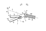
図1は、本実施形態の外科処置具1の構成を示す図である。図1に示すように、外科処置具1は、保持可能なハウジング3と、ハウジング3に連結される筒状のシャフト5と、を備える。シャフト5は、長手軸Cを規定する。ここで、長手軸Cに沿う方向を長手方向とする。長手方向の一方側を先端側(図1の矢印C1側)とし、先端側とは反対側を基端側(図1の矢印C2側)とする。シャフト5は、基端側から先端側へ長手軸Cに沿って延設され、ハウジング3の先端側に連結されている。
FIG. 1 is a diagram showing a configuration of a
シャフト5は、長手軸Cと略同軸の中心軸を有し、ハウジング3に対して長手軸Cを中心として回転可能に取付けられている。シャフト5の基端部には、第1の操作部材である回転操作ノブ18が取付けられている。シャフト5の基端部は、回転操作ノブ18の内部に先端側から挿入され、回転操作ノブ(回転操作入力部)18に対して固定されている。そして、シャフト5は、回転操作ノブ18から先端側に向かって延設されている。また、シャフト5の先端側には、処置対象を処置するエンドエフェクタ7が取付けられている。回転操作ノブ18をハウジング3に対して長手軸Cの軸回りに回転させることにより、エンドエフェクタ7を長手軸Cの軸回りに回転させる操作が、回転操作ノブ18において入力される。回転操作ノブ18での操作入力によって、駆動力(回転駆動力)がシャフト5に伝達され、回転操作ノブ18及びシャフト5が一緒に、ハウジング3に対して長手軸Cの軸回りに回転する。
The
図2は、エンドエフェクタ7の構成を示す図である。図2に示すように、エンドエフェクタ7は、シャフト5に取付けられるエフェクタベース11と、エフェクタベース11に固定される第1の把持片12と、エフェクタベース11に回動可能に連結される第2の把持片13と、を備える。エフェクタベース11は、シャフト5に対して回動軸(屈曲回動軸)P1を中心として回動可能に、シャフト5に取付けられる。回動軸P1は、シャフト5の長手方向に対して交差する(略垂直な)方向に沿って延設される。エフェクタベース11を含むエンドエフェクタ7が、シャフト5に対して回動軸P1の軸回りに回動することにより、エンドエフェクタ7は、図2の矢印B1及び矢印B2で示す方向にシャフト5に対して屈曲動作する。
FIG. 2 is a diagram showing a configuration of the end effector 7. As shown in FIG. 2, the end effector 7 includes an
第2の把持片13は、エフェクタベース11に対して回動軸(開閉回動軸)P2を中心として回動可能である。回動軸P2は、長手方向に対して交差し(略垂直で)、かつ、回動軸P1の延設方向に対して交差する(略垂直な)方向に沿って延設される。第2の把持片13が回動軸P2を中心として回動することにより、エンドエフェクタ7において第1の把持片12と第2の把持片13との間が開く又は閉じる。すなわち、第2の把持片13の回動によって、エンドエフェクタ7が図2の矢印Y1及び矢印Y2で示す方向に開動作又は閉動作する。なお、第1の把持片12及び第2の把持片13の両方がエフェクタベース11に対して(例えば回動軸P2を中心として)回動可能に取付けられてもよい。この場合、第1の把持片12及び第2の把持片13を回動させることにより、第1の把持片12と第2の把持片13との間が開く又は閉じ、エンドエフェクタ7が開動作又は閉動作する。本実施形態では、第1の把持片12と第2の把持片13との間で生体組織等の処置対象を把持して、処置対象を処置する。
The second
図1に示すように、ハウジング3は、長手軸Cに沿って延設されるハウジング本体15と、長手軸Cから離れる側へ向かってハウジング本体15から延設されるグリップ(固定ハンドル)16と、を備える。シャフト5は、ハウジング本体15に先端側から連結される。ハウジング3には、ハンドル(可動ハンドル)17が回動可能に取付けられている。ハンドル17は、長手軸Cに対してグリップ16が位置する側に位置し、本実施形態ではグリップ16に対して先端側に位置している。ハンドル17がハウジング3に対して回動し、ハンドル17がグリップ16に対して開く又は閉じることにより、エンドエフェクタ7を前述のように開動作又は閉動作させる操作が、開閉操作入力部であるハンドル17において、入力される。ハンドル17と第2の把持片13との間は、シャフト5の内部に長手軸Cに沿って延設される可動部材25を介して、連結される。開閉操作入力部であるハンドル17をグリップ16に対して開く又は閉じることにより、可動部材25がシャフト5及びハウジング3に対して長手軸Cに沿って移動し、第2の把持片13が回動軸P2の軸回りに回動する。これにより、一対の把持片12,13の間が開く又は閉じる。
As shown in FIG. 1, the
また、ハウジング3には、エネルギー操作入力部である操作ボタン19A,19Bが取付けられている。操作ボタン19Aで操作入力が行われることにより、例えば、把持片12,13に高周波電気エネルギーが供給される。そして、把持片12,13の間で把持される処置対象に高周波電流を流すことにより、処置対象を処置する。操作ボタン19Bで操作入力が行われることにより、例えば、エンドエフェクタ7に設けられる発熱体(図示しない)に電気エネルギーが供給される。そして、発熱体で発生した熱を用いて処置対象を処置する。なお、エンドエフェクタ7に供給されるエネルギーは、前述のエネルギーに限るものではなく、操作ボタン19A,19Bのそれぞれでの操作入力によって、処置に用いられるエネルギーがエンドエフェクタ7に供給されればよい。
Further, the
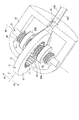
図3及び図4は、ハウジング3の内部及び回転操作ノブ18の内部の構成を示す図である。図3は、斜視図であり、図4は、長手軸Cに略平行な断面を示している。図3及び図4に示すように、ハウジング3(ハウジング本体15)の内部では、ベース部材である筒状の回転ベース22が、シャフト5(回転操作ノブ18)に基端側から取付けられている。回転ベース22は、シャフト5に対する長手軸Cの軸回りの回転は、規制されている。例えば、回転ベース22と回転操作ノブ18との連結部分において、回転ベース22の外周面及び回転操作ノブ18の内周面のそれぞれの長手軸Cに垂直な断面形状を、多角形状又はD字形状等に形成することにより、回転ベース22及びシャフト5の互いに対する長手軸Cの軸回りの回転が、規制される。回転ベース22は、長手軸Cに沿って延設されている。
FIG. 3 and FIG. 4 are views showing the internal configurations of the
回転操作ノブ18での操作入力によって回転操作ノブ18が長手軸Cの軸回りに回転することにより、回転操作ノブ18に対して取付けられた回転ベース22に駆動力(回転駆動力)が伝達され、回転ベース22は、回転操作ノブ18に取付けられたシャフト5と一緒に長手軸Cの軸回りにハウジング3に対して回転する。シャフト5は回転操作ノブ18に対して固定されているため、シャフト5を回転させると回転操作ノブ18を介して回転ベース22に駆動力(回転駆動力)が伝達される。
When the
また、本実施形態では、シャフト5と一緒に可動部材25が、長手軸Cの軸回りに回転可能である。このため、回転操作ノブ18での操作入力によって、エンドエフェクタ7は、シャフト5及び可動部材25と一緒に、ハウジング3に対して長手軸Cを中心として回転する。エンドエフェクタ7が長手軸Cの軸回りに回転することにより、エンドエフェクタ7のハウジング3に対する長手軸Cの軸回りの角度位置が変化する。
In addition, in the present embodiment, the
また、エンドエフェクタ7が回転することにより、回動軸P1,P2もハウジング3に対して長手軸Cの軸回りに回転し、回動軸P1,P2のそれぞれの延設方向も変化する。これにより、エンドエフェクタ7の屈曲動作の屈曲方向(図2の矢印B1側及び矢印B2側)及び開閉動作の開閉方向(図2の矢印Y1側及び矢印Y2側)も変化する。ただし、長手軸Cの軸回りについてエンドエフェクタ7がいずれの角度位置に位置する状態でも、エンドエフェクタ7の屈曲方向は、長手方向に対して交差し(略垂直で)、エンドエフェクタ7の開閉方向は、長手方向に対して交差し(略垂直で)、かつ、屈曲動作の屈曲方向に対して交差する(略垂直である)。
Further, as the end effector 7 rotates, the rotating shafts P1 and P2 also rotate about the longitudinal axis C with respect to the
また、ハウジング3(ハウジング本体15)の内部では、ベース部材である回転ベース30が、回転ベース22に基端側から取付けられている。回転ベース30は、回転ベース22よりも基端側に位置する。回転ベース30は、回転ベース22に対する長手軸C回りの回転が、規制されている。例えば、回転ベース22,30の連結部分において、回転ベース22の外周面及び回転ベース30の内周面のそれぞれの長手軸Cに垂直な断面形状を、多角形状又はD字形状等に形成することにより、回転ベース22,30の互いに対する長手軸Cの軸回りの回転が、規制される。
Further, inside the housing 3 (housing main body 15), a
ハウジング3には、第2の操作部材である屈曲操作ダイヤル20が取付けられている。本実施形態では、屈曲操作ダイヤル(屈曲操作入力部)20は、回転操作ノブ18から基端側へ離れて位置している。屈曲操作ダイヤル20では、エンドエフェクタ7を前述のように屈曲動作させる操作が、入力される。屈曲操作ダイヤル20は、回転ベース30を介して、ハウジング3に取付けられる。回転ベース30及び屈曲操作ダイヤル20は、長手軸Cを中心として、ハウジング3に対して回転可能である。
A bending
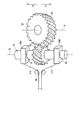
図5は、回転ベース22,30の内部の構成を示す斜視図である。また、図6は、屈曲操作ダイヤル20を示す図である。図4乃至図6に示すように、屈曲操作ダイヤル20は、支持シャフト31を介して回転ベース30に取付けられている。屈曲操作ダイヤル20は、支持シャフト31の中心軸である中心軸R1を中心として、回転ベース30に対して回転可能である。すなわち、中心軸R1は、屈曲操作ダイヤルの中心軸(回転軸)である。中心軸R1を中心として屈曲操作ダイヤル20を回転させることにより、エンドエフェクタ7を屈曲動作させる操作が入力される。この際、図5の矢印Q1及び矢印Q2で示す方向が屈曲操作ダイヤル20での操作方向となる。中心軸R1は、長手軸Cに対して交差する(略垂直な)方向及び屈曲操作ダイヤル20での操作方向に交差する(略垂直な)方向に沿って延設される。
FIG. 5 is a perspective view showing an internal configuration of the
ここで、中心軸R1に沿う方向のうち、一方側を屈曲操作ダイヤル20の第1の幅方向側(図4の矢印W1側)とし、第1の幅方向側とは反対側を第2の幅方向側(図4の矢印W2側)とする。屈曲操作ダイヤル20は、第1の幅方向側を向く第1の側面26と、第2の幅方向側を向く第2の側面27を備える。第1の側面26には、中心軸R1の軸回りに沿って全周に渡ってギア部28が形成されている。本実施形態では、ギア部28の一部が、ハウジング3の外部に露出している。
Here, of the directions along the central axis R1, one side is the first width direction side of the bending operation dial 20 (arrow W1 side in FIG. 4), and the side opposite to the first width direction side is the second side. The width direction side (arrow W2 side in FIG. 4) is set. The bending
回転ベース22の内部には、回転子であるシャフト35が設けられている。図7は、シャフト35を示す図である。図5及び図7に示すように、シャフト35は中心軸(回転軸)R2を有する。本実施形態では、中心軸R2は、長手軸Cと略平行に延設されている。ある実施例では、中心軸R2は、長手軸Cと略一致する(同軸である)。シャフト35は、中心軸R2に沿って延設されている。シャフト35は、回転ベース22に対する中心軸R2に沿う方向への移動が規制された状態で、回転ベース22に取付けられている。シャフト35は、中心軸R2を中心として、回転ベース22に対して回転可能である。
A
シャフト35の基端部には、中心軸R2の軸回りに沿って全周に渡ってギア部37が形成されている。ギア部37は、屈曲操作ダイヤル20のギア部28と噛合う。屈曲操作ダイヤル20での操作入力によって屈曲操作ダイヤル20が中心軸R1の軸回りに回転することにより、ギア部28を介して、ギア部37に駆動力(回転駆動力)が伝達され、シャフト35が中心軸R2の軸回りに回転する。本実施形態では、ギア部28及びギア部37には、ベベルギア(傘歯車)が用いられているがこれに限るものではない。例えば、ギア部28にクラウンギア(冠歯車)が用いられるとともに、ギア部37にスパーギア(平歯車)が用いられてもよい。
A
シャフト35は、右ネジ部(第1のネジ部)38と、左ネジ部(第2のネジ部)39と、を備える。右ネジ部38には、中心軸R2の軸回りに沿って右ネジが形成されている。左ネジ部39には、中心軸R2の軸回りに沿って左ネジが形成されている。したがって、左ネジ部39は、右ネジ部38に対して巻き方向が逆になり、右ネジ部38に対して逆ネジに形成されている。
The
右ネジ部38には、第1の連結部材であるナット40Aが螺合している。また、左ネジ部39には、第2の連結部材であるナット40Bが螺合している。図8は、ナット40Bを示す図である。ナット40Aの内周面には、右ネジの雌ネジが形成されている。また、ナット40Bの内周面には、左ネジの雌ネジが形成されている。ナット40A,40Bは、回転ベース22に取付けられている。ナット40A,40Bは、回転ベース22に対する中心軸R2の軸回りの回転が、規制されている。また、ナット40A,40Bは、回転ベース22に対して中心軸R2に沿って移動可能である。
A
屈曲操作ダイヤル20での操作入力によってシャフト35が中心軸R2の軸回りに回転することにより、右ネジ部38がナット40Aに対して中心軸R2の軸回りに回転し、左ネジ部39がナット40Bに対して中心軸R2の軸回りに回転する。これにより、ナット40A,40Bは、シャフト35に対して中心軸R2に沿って移動する。すなわち、回転子であるシャフト35は、屈曲操作ダイヤル20での操作入力によって発生した中心軸R2の軸回りの回転運動を、ナット40A,40Bの中心軸R2に沿う方向への直進運動に変換している。左ネジ部39は、右ネジ部38に対して巻き方向が逆である。このため、ナット40A,40Bは、中心軸R2に沿って互いに対して反対側に移動する。
When the
ナット40Aには、伝達部材である屈曲ワイヤ41Aの基端(一端)が接続されている。屈曲ワイヤ(屈曲駆動部材)41Aは、長手軸Cに沿って延設され、回転ベース22の内部及びシャフト5の内部を通って先端側へ向かって延設されている。また、ナット40Bには、伝達部材である屈曲ワイヤ41Bの基端(一端)が接続されている。屈曲ワイヤ(屈曲駆動部材)41Bは、長手軸Cに沿って延設され、回転ベース22の内部及びシャフト5の内部を通って先端側へ向かって延設されている。
A proximal end (one end) of a
図2に示すように、屈曲ワイヤ41A,41Bの先端(他端)は、エンドエフェクタ7のエフェクタベース11に接続されている。屈曲操作ダイヤル20での操作入力によってシャフト35が中心軸R2の軸回りに回転することにより、ナット40A,40Bが中心軸R2に沿って回転ベース22に対して互いに反対側に移動する。これにより、伝達部材である屈曲ワイヤ41A,41Bが駆動され、屈曲ワイヤ41A,41Bがシャフト5に対して長手軸Cに沿って移動する。屈曲ワイヤ41A,41Bが移動することにより、エンドエフェクタ7が前述のようにシャフト5に対して屈曲動作する。すなわち、伝達部材である屈曲ワイヤ41A,41Bは、エンドエフェクタ7を屈曲動作させる駆動力をエンドエフェクタ7に伝達する。
As shown in FIG. 2, the ends (other ends) of the bending
例えば、屈曲操作ダイヤル20を操作方向の一方側(図5の矢印Q1側)へ移動させる操作入力によって屈曲操作ダイヤル20を回転方向の一方側(図5の矢印T1側)に回転すると、シャフト35が回転方向の一方側(図5の矢印Z1側)へ回転する。これにより、ナット40Aがシャフト35及び回転ベース22に対して先端側に移動するとともに、ナット40Bがシャフト35及び回転ベース22に対して基端側に移動する。したがって、ナット40A及びナット40Bが互いに対して反対側に移動する。そして、ナット40Aに接続される屈曲ワイヤ41Aが先端側へ移動する(弛緩される)とともに、ナット40Bに接続される屈曲ワイヤ41Bが基端側へ移動し(牽引され)、屈曲方向の一方側(図2の矢印B2側)へエンドエフェクタ7がシャフト5(長手軸C)に対して屈曲する。
For example, when the bending
一方、屈曲操作ダイヤル20を操作方向の他方側(図5の矢印Q2側)へ移動させる操作入力によって屈曲操作ダイヤル20を回転方向の他方側(図5の矢印T2側)に回転すると、シャフト35が回転方向の他方側(図5の矢印Z2側)へ回転する。これにより、ナット40Aがシャフト35及び回転ベース22に対して基端側に移動するとともに、ナット40Bがシャフト35及び回転ベース22に対して先端側に移動する。したがって、ナット40A及びナット40Bが互いに対して反対側に移動する。そして、屈曲ワイヤ41Aが基端側へ移動するとともに、屈曲ワイヤ41Bが先端側へ移動し、屈曲方向の他方側(図2の矢印B1側)へエンドエフェクタ7がシャフト5(長手軸C)に対して屈曲する。
On the other hand, when the bending
なお、ナット40Aに屈曲ワイヤ41Bが接続され、ナット40Bに屈曲ワイヤ41Aが接続されてもよい。この場合、例えば、屈曲操作ダイヤル20を操作方向の一方側(図5の矢印Q1側)へ移動させる操作入力によって、ナット40Aに接続される屈曲ワイヤ41Bが先端側へ移動する(弛緩される)とともに、ナット40Bに接続される屈曲ワイヤ41Aが基端側へ移動し(牽引され)、屈曲方向の一方側(図2の矢印B1側)へエンドエフェクタ7がシャフト5(長手軸C)に対して屈曲する。また、屈曲操作ダイヤル20を操作方向の他方側(図5の矢印Q2側)へ移動させる操作入力によって、ナット40Aに接続される屈曲ワイヤ41Bが基端側へ移動する(牽引される)とともに、ナット40Bに接続される屈曲ワイヤ41Aが先端側へ移動し(弛緩され)、屈曲方向の他方側(図2の矢印B2側)へエンドエフェクタ7がシャフト5(長手軸C)に対して屈曲する。
The
また、ハウジング3(ハウジング本体15)の内部では、回転ベース22に基端側から回転ベース30が連結されている。回転ベース22及び回転ベース30の長手軸Cの軸回りについての互いに対する回転は、規制されている。したがって、シャフト5と屈曲操作ダイヤル20との間を連結する回転ベース22,30は、シャフト5及び屈曲操作ダイヤル20と一緒に長手軸Cの軸回りに回転可能である。
Further, inside the housing 3 (housing main body 15), the
前述のような構成であるため、回転操作ノブ(第1の操作部材)18での操作入力によって、エンドエフェクタ7、シャフト5及び回転ベース22が長手軸Cの軸回りに回転することにより、シャフト5から回転ベース22を介して回転ベース30に駆動力(回転駆動力)が伝達される。これにより、回転ベース22,30は、エンドエフェクタ7及びシャフト5と一緒に長手軸Cを中心としてハウジング3に対して回転する。この際、回転ベース22に取付けられるシャフト35及びナット40A,40Bにも回転ベース22から駆動力(回転駆動力)が伝達され、シャフト35及びナット40A,40Bは、回転ベース22と一緒に長手軸Cの軸回りにハウジング3に対して回転する。また、回転ベース30に取付けられる屈曲操作ダイヤル20及び支持シャフト31にも回転ベース30から駆動力(回転駆動力)が伝達され、屈曲操作ダイヤル20及び支持シャフト31は、回転ベース30と一緒に長手軸Cの軸回りにハウジング3に対して回転する。すなわち、本実施形態では、第1の操作部材である回転操作ノブ18での操作入力によってシャフト5がハウジング3に対して長手軸Cの軸回りに回転することにより、第2の操作部材である屈曲操作ダイヤル20及びエンドエフェクタ7も、シャフト5と一緒に長手軸Cの軸回りにハウジング3に対して回転する。また、回転操作ノブ18での操作入力によってエンドエフェクタ7及びシャフト35がハウジング3に対して長手軸Cの軸回りに回転することにより、エンドエフェクタ7とシャフト35との間を接続する屈曲ワイヤ41A,41Bも、長手軸Cの軸回りに回転する。
Since the configuration is as described above, the end effector 7, the
また、シャフト35及び屈曲操作ダイヤル20が回転することにより、中心軸R1,R2もハウジング3に対して長手軸Cの軸回りに回転する。この際、中心軸R1の延設方向も変化する。これにより、屈曲操作ダイヤル20の回転方向(図5の矢印T1側及び矢印T2側)も変化し、屈曲操作ダイヤル20での操作入力における操作方向(図5の矢印Q1側及び矢印Q2側)が変化する。ただし、長手軸Cの軸回りについて回転ベース30及び屈曲操作ダイヤル20がいずれの角度位置に位置する状態でも、屈曲操作ダイヤル20での操作方向は、長手軸C及び中心軸R2に対して交差し(略垂直で)、かつ、中心軸R1の延設方向に対して交差する(略垂直である)。
Further, as the
前述のように、本実施形態では、回転操作ノブ18での操作入力によって、シャフト5、エンドエフェクタ7及び屈曲操作ダイヤル20が一緒に、長手軸Cの軸回りに回転する。このため、エンドエフェクタ7の回転によってエンドエフェクタ7の長手軸Cの軸回りの角度位置が変化しても、エンドエフェクタ7の角度位置の変化に対応して屈曲操作ダイヤル20の長手軸Cの軸回りの角度位置が変化する。したがって、回転操作ノブ18で操作入力が行われても、エンドエフェクタ7の屈曲方向(図2の矢印B1側及び矢印B2側)の変化に対応して、屈曲操作ダイヤル20での操作方向(図5の矢印Q1側及び矢印Q2側)が変化する。例えば、ある実施例では、エンドエフェクタ7の屈曲方向及び屈曲操作ダイヤル20での操作方向が略平行な状態から、回転操作ノブ18での操作入力によってエンドエフェクタ7を長手軸Cの軸回りに回転させる。この際、エンドエフェクタ7と一緒に屈曲操作ダイヤル20も長手軸Cの軸回りに回転するため、エンドエフェクタ7の長手軸Cの軸回りの角度位置が変化しても、エンドエフェクタ7の屈曲方向及び屈曲操作ダイヤル20での操作方向が略平行な状態が保たれる。すなわち、本実施形態では、回転操作ノブ18での操作入力が行われても、エンドエフェクタ7の屈曲方向及び屈曲操作ダイヤル20での操作方向の相対関係が変化することなく、エンドエフェクタ7及び屈曲操作ダイヤル20が一緒に長手軸Cの軸回りに回転する。また、回転操作ノブ18での操作入力が行われても、エンドエフェクタ7の屈曲方向及び屈曲操作ダイヤル20での操作方向の相対関係が変化することなく、屈曲操作ダイヤル20での操作入力による駆動力がエンドエフェクタ7まで伝達される。
As described above, in the present embodiment, the
次に、本実施形態の外科処置具1の作用及び効果について説明する。外科処置具1を用いて処置を行う際には、腹腔等の体腔内にエンドエフェクタ7を挿入する。そして、処置対象にエンドエフェクタ7をアプローチする。この際、回転操作ノブ18での操作入力によってエンドエフェクタ7を長手軸Cの軸回りに回転させたり、屈曲操作ダイヤル20での操作入力によってエンドエフェクタ7をシャフト5に対して屈曲動作させたりして、処置対象を把持し易い位置にエンドエフェクタ7を配置する。そして、処置対象を一対の把持片12,13の間に位置させ、ハンドル17での操作入力によってエンドエフェクタ7を閉動作させる。これにより、把持片12,13の間で処置対象が把持される。この状態で、操作ボタン19A又は19Bで操作入力が行われることにより、エネルギーがエンドエフェクタ7に供給され、エネルギー(処置エネルギー)を用いて処置対象が処置される。
Next, the operation and effect of the
本実施形態では、回転操作ノブ18での操作入力によって、シャフト5、エンドエフェクタ7及び屈曲操作ダイヤル20が一緒に、長手軸Cの軸回りに回転する。このため、エンドエフェクタ7のハウジング3に対する長手軸Cの軸回りの角度位置が変化しても、屈曲操作ダイヤル20のシャフト5及びエンドエフェクタ7に対する長手軸Cの軸回りの相対的な角度位置は、変化しない。すなわち、回転操作ノブ18での操作入力が行われても、エンドエフェクタ7の屈曲方向(図2の矢印B1側及び矢印B2側)及び屈曲操作ダイヤル20での操作方向(図5の矢印Q1側及び矢印Q2側)の相対関係が変化することなく、エンドエフェクタ7及び屈曲操作ダイヤル20が一緒に長手軸Cの軸回りに回転する。このため、術者は、エンドエフェクタ7が長手軸Cの軸回りについていずれの角度位置に位置する状態でも、エンドエフェクタ7の屈曲方向を把握し易い。
In this embodiment, the
前述のように、本実施形態では、エンドエフェクタ7の長手軸Cの軸回りについての角度位置に関係なく、エンドエフェクタ7をシャフト5に対して屈曲動作させる操作の操作性が確保される外科処置具1を提供することができる。
As described above, in the present embodiment, regardless of the angular position of the longitudinal axis C of the end effector 7 about its axis, a surgical procedure that ensures the operability of the bending operation of the end effector 7 with respect to the
(第1の実施形態の第1の変形例)
図9及び図10は、第1の実施形態の第1の変形例における屈曲操作ダイヤル20の構成を示す図である。図9は、第1の幅方向側から視た図であり、図10は、屈曲操作ダイヤル20を長手軸C及び中心軸R1に沿う断面で示している。図9及び図10に示すように、本変形例では、屈曲操作ダイヤル20の第1の側面26には、中心軸R1の軸回りの一部のみにギア部28が設けられている。ギア部28は、中心軸R1の軸回りについて、屈曲操作ダイヤル20がハウジング3から外部に露出する部分以外の範囲内に、設けられる。(First Modification of First Embodiment)
9 and 10 are diagrams showing the configuration of the bending
本変形例では、屈曲操作ダイヤル20がハウジング3から外部に露出する部分には、ギア部28は設けられていない。したがって、術者によって屈曲操作ダイヤル20での操作入力が行われる部分には、ギア部28は形成されていない。このため、術者は、屈曲操作ダイヤル20のギア部28が形成されていない部分を操作することにより、安全に屈曲操作ダイヤル20での操作入力を行うことができる。
In the present modification, the
(第1の実施形態の第2の変形例)
図11は、第1の実施形態の第2の変形例における回転ベース22,30の内部の構成を示す図である。図11に示すように、本変形例では、屈曲操作ダイヤル20の第1の側面26には、ギア部(28)は設けられていない。また、第2の側面27には、平歯車56が取付けられている。屈曲操作ダイヤル20での操作入力によって屈曲操作ダイヤル20が中心軸R1の軸回りに回転ベース30に対して回転することにより、平歯車56は、屈曲操作ダイヤル20と一緒に中心軸R1の軸回りに回転ベース30に対して回転する。平歯車56は、ハウジング3の内部において屈曲操作ダイヤル20に取付けられている。(Second Modification of First Embodiment)
FIG. 11 is a diagram showing an internal configuration of the rotation bases 22 and 30 in the second modified example of the first embodiment. As shown in FIG. 11, in this modified example, the gear portion (28) is not provided on the
平歯車56の先端側には、平歯車56と噛合う平歯車57が、設けられている。平歯車57は、例えば、回転ベース22の内部に取付けられている。平歯車57は中心軸(回転軸)R3を有する。中心軸R3は、中心軸R1と略平行に延設されている。平歯車57は、回転ベース22に対して中心軸R3の軸回りに回転可能である。また、平歯車57の回転ベース22に対する移動は、中心軸R3の軸回りの回転を除いて、規制されている。屈曲操作ダイヤル20での操作入力によって平歯車56が中心軸R1の軸回りに回転することにより、平歯車56を介して平歯車57に駆動力が伝達される。そして、平歯車57が中心軸R3の軸回りに回転ベース22に対して回転する。
A
平歯車57には、ギア部58が取付けられている。ギア部58は、シャフト35のギア部37と噛合う。ギア部58は、回転ベース22に対して中心軸R3の軸回りに平歯車57と一緒に回転する。屈曲操作ダイヤル20での操作入力によってギア部58及び平歯車57が中心軸R3の軸回りに回転することにより、ギア部58を介してギア部37に駆動力が伝達される。そして、ギア部37及びシャフト35が中心軸(回転軸)R2の軸回りに回転ベース22に対して回転する。
A
回転操作ノブ18での操作入力によって、エンドエフェクタ7、シャフト5、回転ベース22,30及び屈曲操作ダイヤル20が一緒に、長手軸Cを中心としてハウジング3に対して回転する。この際、回転ベース22,30のいずれかに取付けられるシャフト35、ナット40A,40B、平歯車56,57及びギア部58にも回転ベース22から駆動力(回転駆動力)が伝達され、シャフト35、ナット40A,40B、平歯車56,57及びギア部58は、回転ベース22と一緒に長手軸Cの軸回りにハウジング3に対して回転する。このため、回転操作ノブ18での操作入力が行われても、エンドエフェクタ7の屈曲方向及び屈曲操作ダイヤル20での操作方向の相対関係が変化することなく、屈曲操作ダイヤル20での操作入力による駆動力がエンドエフェクタ7まで伝達される。
The end effector 7, the
本変形例では、ハウジング3の内部において平歯車56が取付けられている。このため、屈曲操作ダイヤル20においてハウジング3から外部に露出する部分には、ギア部(28)が形成されていない。このため、術者は、安全に屈曲操作ダイヤル20での操作入力を行うことができる。
In this modification, a
(第1の実施形態の第3の変形例)
図12は、第1の実施形態の第3の変形例の回転ベース22,30の内部構成を示す図である。図12に示すように、本変形例では、屈曲操作ダイヤル20のギア部28には、クラウンギアが用いられている。(Third Modification of First Embodiment)
FIG. 12: is a figure which shows the internal structure of the rotation bases 22 and 30 of the 3rd modification of 1st Embodiment. As shown in FIG. 12, in this modification, a crown gear is used for the
本変形例では、回転子であるシャフト35は、第1の回転部材60及び第2の回転部材64を備える。本変形例でも、シャフト35は、回転軸として中心軸R2を有する。第1の回転部材60は、基端部に形成されるギア部61と、先端部に設けられる差し込み部62と、ギア部61と差し込み部62との間に設けられる左ネジ部(第1のネジ部)63と、を備える。ギア部61は、屈曲操作ダイヤル20のギア部28と噛合う。ギア部61は、スパーギア(平歯車)が用いられる。そして、ギア部61は、中心軸R2に沿う方向について、ある程度の大きさの寸法(嵌合長さ)を有する。このため、シャフト35のギア部61及び屈曲操作ダイヤル20のギア部28は、互いに対する噛合いを維持したまま、中心軸R2に沿って互いに対して移動可能である。左ネジ部63には、中心軸R2の軸回りに沿って左ネジが形成されている。
In this modification, the
差し込み部62は、第1の回転部材60の先端部において、中心軸R2に沿って延設されている。差し込み部62では、中心軸R2に交差する(略垂直な)断面は、例えば、D字形状又は多角形状等に形成されている。
The insertion portion 62 extends along the central axis R2 at the tip of the first rotating
差し込み部62には、第2の回転部材64が取付けられている。第2の回転部材64は、中心軸R2に沿って延設される連結孔65を備える。差し込み部62は、基端側から連結孔65に挿通され、連結孔65と嵌合している。差し込み部62では、中心軸R2に交差する(略垂直な)断面は、差し込み部62に対応する形状であり、例えば、D字形状又は多角形状等に形成されている。このため、第2の回転部材64は、第1の回転部材60に対する中心軸R2の軸回りの回転が、規制されている。したがって、第1の回転部材60が中心軸R2の軸回りに回転ベース22に対して回転することにより、第2の回転部材64は、第1の回転部材60と一緒に中心軸R2の軸回りに回転し、シャフト35全体が中心軸R2の軸回りに回転する。また、第2の回転部材64は、第1の回転部材60に対して中心軸R2に沿って移動可能である。すなわち、回転部材60,64は、互いに対して中心軸R2に沿って移動可能である。
A second rotating
第2の回転部材64は、右ネジ部(第2のネジ部)66を備える。右ネジ部66には、中心軸R2の軸回りに沿って右ネジが形成されている。したがって、右ネジ部66は、左ネジ部63に対して巻き方向が逆になり、左ネジ部63に対して逆ネジが形成されている。
The second rotating
シャフト35の左ネジ部63には、第1の連結部材であるナット40Aが螺合している。また、回転部材64の右ネジ部66には、第2の連結部材であるナット40Bが螺合している。本変形例では、ナット40A,40Bは、回転ベース22に固定され、回転ベース22に対する回転及び移動が、規制されている。
A
屈曲操作ダイヤル20での操作入力によってシャフト35が中心軸R2の軸回りに回転ベース22に対して回転することにより、左ネジ部63及び右ネジ部66が、シャフト35と一緒に中心軸R2の軸回りに回転する。このとき、左ネジ部63は、ナット40Aに対して中心軸R2の軸回りに回転する。これにより、左ネジ部63が、ナット40A及び回転ベース22に対して中心軸R2に沿って移動する。また、右ネジ部66は、ナット40Bに対して中心軸R2の軸回りに回転する。これにより、右ネジ部66が、ナット40B及び回転ベース22に対して中心軸R2に沿って移動する。すなわち、回転子であるシャフト35は、屈曲操作ダイヤル20での操作入力によって発生した中心軸R2の軸回りの回転運動を、左ネジ部63及び右ネジ部66の中心軸R2に沿う方向への直進運動に変換している。
When the
また、左ネジ部63及び右ネジ部66には、互いに対して巻き方向が逆である。このため、屈曲操作ダイヤル20での操作入力によって、左ネジ部63(第1の回転部材60)及び右ネジ部66(第2の回転部材64)は、中心軸R2に沿って、回転ベース22に対して互いに反対側に移動する。
The left threaded
本変形例では、第1の回転部材60には、屈曲ワイヤ41Aの基端(一端)が接続されている。第2の回転部材64には、屈曲ワイヤ41Bの基端(一端)が接続されている。このため、回転部材60,64が、中心軸R2に沿って互いに対して反対側に移動することにより、屈曲ワイヤ41A,41Bが駆動され、エンドエフェクタ7が屈曲動作する。
In the present modification, the base end (one end) of the
回転操作ノブ18での操作入力によって、エンドエフェクタ7、シャフト5、回転ベース22,30及び屈曲操作ダイヤル20が一緒に、長手軸Cを中心としてハウジング3に対して回転する。この際、回転ベース22に取付けられるナット40A,40Bを介してシャフト35にも回転ベース22から駆動力(回転駆動力)が伝達され、シャフト35及びナット40A,40Bは、回転ベース22と一緒に長手軸Cの軸回りにハウジング3に対して回転する。このため、回転操作ノブ18での操作入力が行われても、エンドエフェクタ7の屈曲方向及び屈曲操作ダイヤル20での操作方向の相対関係が変化することなく、屈曲操作ダイヤル20での操作入力による駆動力がエンドエフェクタ7まで伝達される。
The end effector 7, the
(第2の実施形態)
次に、本発明の第2の実施形態について、図13を参照して、説明する。第1の実施形態と同一の部分については同一の符号を付して、その説明は省略する。図13は、本実施形態における回転ベース22,30の内部の構成を示す図である。図13に示すように、本実施形態では、屈曲操作ダイヤル20の第2の側面27には、ギア部29が設けられている。ギア部29は、第2の側面27において中心軸R1の軸回りに全周に渡って形成されている。(Second embodiment)
Next, a second embodiment of the present invention will be described with reference to FIG. The same parts as those in the first embodiment are designated by the same reference numerals, and the description thereof will be omitted. FIG. 13 is a diagram showing an internal configuration of the rotation bases 22 and 30 in this embodiment. As shown in FIG. 13, in the present embodiment, a
回転ベース22の内部には、第1の回転子である第1のシャフト71Aと、第2の回転子である第2のシャフト71Bが取付けられている。第1のシャフト71Aは、中心軸(第1の回転軸)R4に沿って延設されている。第2のシャフト71Bは、中心軸(第2の回転軸)R5に沿って延設されている。中心軸R4及び中心軸R5は、長手軸Cに対して略平行である。シャフト71A,71Bは、回転ベース22に対する中心軸R4,R5に沿う移動が規制されている。また、第1のシャフト71Aは、回転ベース22に対して中心軸R4の軸回りに回転可能であり、第2のシャフト71Bは、回転ベース22に対して中心軸R5の軸回りに回転可能である。
Inside the
第1のシャフト71Aの基端部には、ギア部72Aが設けられている。ギア部72Aは、屈曲操作ダイヤル20に第1の幅方向側から当接し、ギア部28と噛合っている。屈曲操作ダイヤル20が中心軸R1の軸回りに回転することにより、ギア部28を介してギア部72Aに駆動力が伝達され、第1のシャフト71Aが中心軸R4の軸回りに回転ベース22に対して回転する。
A
第1のシャフト71Aは、右ネジ部(第1のネジ部)73Aを備える。右ネジ部73Aには、中心軸R4の軸回りに沿って右ネジが形成されている。右ネジ部73Aには、第1の連結部材であるナット74Aが螺合している。ナット74Aは、回転ベース22に取付けられている。ナット74Aは、回転ベース22に対する中心軸R4の軸回りの回転が規制されている。また、ナット74Aは、回転ベース22に対して中心軸R4に沿って移動可能である。このため、第1のシャフト71Aが回転ベース22に対して中心軸R4の軸回りに回転することにより、右ネジ部73Aがナット74Aに対して中心軸R4の軸回りに回転し、ナット74Aがシャフト71A及び回転ベース22に対して中心軸R4に沿って移動する。ナット74Aには、屈曲駆動部材(伝達部材)である屈曲ワイヤ41Aの基端(一端)が接続されている。
The
また、第2のシャフト71Bの基端部には、ギア部72Bが設けられている。ギア部72Bは、屈曲操作ダイヤル20に第2の幅方向側から当接し、ギア部29と噛合っている。屈曲操作ダイヤル20が中心軸R1の軸回りに回転することにより、ギア部29を介してギア部72Bに駆動力が伝達され、第2のシャフト71Bが中心軸R5の軸回りに回転ベース22に対して回転する。
A gear portion 72B is provided at the base end portion of the second shaft 71B. The gear portion 72B is in contact with the bending
第2のシャフト71Bは、右ネジ部(第2のネジ部)73Bを備える。右ネジ部73Bには、中心軸R5の軸回りに沿って右ネジが形成されている。したがって、右ネジ部73Bは、右ネジ部73Aに対して巻き方向が同一である。右ネジ部73Bには、第2の連結部材であるナット74Bが螺合している。ナット74Bは、回転ベース22に取付けられている。ナット74Bは、回転ベース22に対する中心軸R5の軸回りの回転が規制されている。また、ナット74Bは、回転ベース22に対して中心軸R5に沿って移動可能である。このため、第2のシャフト71Bが回転ベース22に対して中心軸R5の軸回りに回転することにより、右ネジ部73Bがナット74Bに対して中心軸R5の軸回りに回転し、ナット74Bがシャフト71B及び回転ベース22に対して中心軸R5に沿って移動する。ナット74Bには、屈曲駆動部材(伝達部材)である屈曲ワイヤ41Bの基端(一端)が接続されている。
The second shaft 71B includes a right screw portion (second screw portion) 73B. A right-hand thread is formed on the right-
本実施形態においても、回転子であるシャフト71Aは、屈曲操作ダイヤル20での操作入力による中心軸R4の軸回りの回転運動を、ナット74Aの中心軸R4に沿う方向への直進運動に変換している。また、回転子であるシャフト71Bは、屈曲操作ダイヤル20での操作入力による中心軸R5の軸回りの回転運動を、ナット74Bの中心軸R5に沿う方向への直進運動に変換している。
Also in the present embodiment, the
なお、ある実施例では、ギア部28,29,72A,72Bに、ベベルギアが用いられる。また、ギア部28,29に、クラウンギアが用いられ、ギア部72A,72Bにスパーギアが用いられてもよい。
In one embodiment, bevel gears are used for the
本実施形態では、屈曲操作ダイヤル20での操作入力によって、シャフト71Aが中心軸R4の軸回りに回転ベース22に対して回転するとともに、シャフト71Bが中心軸R5を中心としてシャフト71Aとは反対回りに回転ベース22に対して回転する。したがって、右ネジ部73A及び右ネジ部73Bは、互いに対して反対回りに回転する。このため、ナット74A及びナット74Bは、長手軸Cに略平行な方向について、互いに対して反対側に移動する。ナット74A及びナット74Bが互いに対して反対側に移動することにより、屈曲ワイヤ41A,41Bが駆動され、エンドエフェクタ7が屈曲動作する。
In the present embodiment, the
回転操作ノブ18での操作入力によって、エンドエフェクタ7、シャフト5、回転ベース22,30及び屈曲操作ダイヤル20が一緒に、長手軸Cを中心としてハウジング3に対して回転する。この際、回転ベース22に取付けられるシャフト71A,71B及びナット74A,74Bにも回転ベース22から駆動力(回転駆動力)が伝達され、シャフト71A,71B及びナット74A,74Bは、回転ベース22と一緒に長手軸Cの軸回りにハウジング3に対して回転する。このため、回転操作ノブ18での操作入力が行われても、エンドエフェクタ7の屈曲方向及び屈曲操作ダイヤル20での操作方向の相対関係が変化することなく、屈曲操作ダイヤル20での操作入力による駆動力がエンドエフェクタ7まで伝達される。
The end effector 7, the
(第2の実施形態の変形例)
なお、第2の実施形態のある変形例では、第1のシャフト(第1の回転子)71Aの右ネジ部73Aに屈曲ワイヤ41Bが接続され、第2のシャフト(第2の回転子)71Bの右ネジ部73Bに屈曲ワイヤ41Aが接続される。この場合、ナット(第1の連結部材)74Aの回転ベース22に対する中心軸R4に沿う移動は規制され、ナット(第2の連結部材)74Bの回転ベース22に対する中心軸R5に沿う移動は規制される。そして、シャフト71Aは、中心軸R4に沿って回転ベース22及びナット74Aに対して移動可能であり、シャフト71Bは、中心軸R5に沿って回転ベース22及びナット74Bに対して移動可能である。本変形例では、例えば、屈曲操作ダイヤル20を操作方向の一方側へ移動させる操作入力によって、シャフト71Aに接続される屈曲ワイヤ41Bが先端側へ移動する(弛緩される)とともに、シャフト71Bに接続される屈曲ワイヤ41Aが基端側へ移動し(牽引され)、屈曲方向の一方側(図2の矢印B1側)へエンドエフェクタ7がシャフト5(長手軸C)に対して屈曲する。また、屈曲操作ダイヤル20を操作方向の他方側へ移動させる操作入力によって、屈曲ワイヤ41Bが基端側へ移動するとともに、屈曲ワイヤ41Aが先端側へ移動し、屈曲方向の他方側(図2の矢印B2側)へエンドエフェクタ7がシャフト5(長手軸C)に対して屈曲する。(Modification of the second embodiment)
In a modification of the second embodiment, the
(第3の実施形態)
次に、本発明の第3の実施形態について、図14を参照して、説明する。第1の実施形態と同一の部分については同一の符号を付して、その説明は省略する。図14は、本実施形態における回転ベース30の内部の構成を示す図である。図14に示すように、本実施形態では、屈曲操作ダイヤル20は、屈曲操作ダイヤル20を中心軸R1に沿って貫通し、内周面に歯車が形成されるギア部77を備える。ギア部77は、中心軸R1の軸回りに沿って形成されている。(Third Embodiment)
Next, a third embodiment of the present invention will be described with reference to FIG. The same parts as those in the first embodiment are designated by the same reference numerals, and the description thereof will be omitted. FIG. 14 is a diagram showing an internal configuration of the
ギア部77には、回転子である、シャフト81が挿通されている。シャフト81は、中心軸(回転軸)R6に沿って延設され、回転ベース30の内部に取付けられている。中心軸R6は、中心軸R1と略平行である。すなわち、中心軸R6は、長手軸Cに交差している(略垂直である)。シャフト81は、回転ベース30に対して中心軸R6の軸回りに回転可能である。また、シャフト81の回転ベース30に対する中心軸R6に沿う移動は、規制されている。
A
シャフト81は、ギア部82を備える。ギア部82は、屈曲操作ダイヤル20のギア部77と噛合う。ギア部77及びギア部82には、例えば、スパーギア(平歯車)が用いられる。屈曲操作ダイヤル20での操作入力によって屈曲操作ダイヤル20が中心軸R1の軸回りに回転することにより、ギア部77を介してギア部82に駆動力が伝達される。そして、シャフト81が中心軸R6の軸回りに回転する。本実施形態では、長手軸Cは、ギア部82を通る。
The
シャフト81は、第1の左ネジ部(第1のネジ部)83と、第2の左ネジ部(第2のネジ部)84と、を備える。第1の左ネジ部83及び第2の左ネジ部84のそれぞれには、中心軸R6の軸回りに沿って左ネジが形成されている。第2の左ネジ部84は、第1の左ネジ部83に対して、巻方向が同一である。第2の左ネジ部84は、ギア部82に対して第1の幅方向側に位置する。また、第2の左ネジ部84は、ギア部82に対して第2の幅方向側に位置する。したがって、第1の左ネジ部83及び第2の左ネジ部84は、ギア部82に対して互いに反対側に位置している。すなわち、第1の左ネジ部83及び第2の左ネジ部84は、長手軸Cに対して互いに反対側に位置する。
The
第1の左ネジ部83には、第1の連結部材であるナット85Aが螺合している。また、第2の左ネジ部84には、第2の連結部材であるナット85Bが螺合している。ナット85A,85Bは、ギア部82に対して互いに反対側に位置している。ナット85A,85Bは、回転ベース30に取付けられ、回転ベース30に対する中心軸R6の軸回りの回転が規制されている。ナット85A,85Bは、回転ベース30に対して中心軸R6に沿って移動可能である。
A
屈曲操作ダイヤル20での操作入力によってシャフト81が中心軸R6の軸回りに回転ベース30に対して回転することにより、左ネジ部83,84が、シャフト81と一緒に中心軸R6の軸回りに回転する。このとき、左ネジ部83は、ナット85Aに対して中心軸R6の軸回りに回転する。これにより、ナット85Aが、左ネジ部83及び回転ベース30に対して中心軸R6に沿って移動する。また、左ネジ部84は、ナット85Bに対して中心軸R6回りに回転する。これにより、ナット85Bが、左ネジ部84及び回転ベース30に対して中心軸R6に沿って移動する。
When the
本実施形態においても、回転子であるシャフト81は、屈曲操作ダイヤル20での操作入力による中心軸R6の軸回りの回転運動を、ナット85A,85Bの中心軸R6に沿う方向への直進運動に変換している。
Also in the present embodiment, the
ナット85A,85Bは、長手軸Cに対して互いに反対側の位置において、長手軸Cに略垂直な方向(中心軸R6に沿う方向)について、同じ方向に移動する。このため、長手軸Cに略垂直な方向(中心軸R6に沿う方向)について、ナット85A,85Bの一方が、長手軸Cに対して離れるとともに、ナット85A,85Bの他方が、長手軸Cに対して近づく。 The nuts 85A and 85B move at the positions opposite to each other with respect to the longitudinal axis C, in the same direction with respect to the direction substantially perpendicular to the longitudinal axis C (direction along the central axis R6). Therefore, in the direction substantially perpendicular to the longitudinal axis C (direction along the central axis R6), one of the nuts 85A and 85B is separated from the longitudinal axis C, and the other of the nuts 85A and 85B is moved to the longitudinal axis C. Approach.
本実施形態では、ナット85Aには、屈曲ワイヤ41Aの基端(一端)が接続されている。ナット85Bには、屈曲ワイヤ41Bの基端(一端)が接続されている。また、回転ベース30の先端面には、ガイド部86が設けられている。ガイド部86は、回転ベース30の先端壁を基端側から先端側に貫通する孔である。屈曲ワイヤ41A,41Bは、エンドエフェクタ7から基端側へ延設され、ガイド部86を通って、ナット85A,85Bに接続されている。本実施形態では、長手軸Cは、ガイド部86を通る。すなわち、ガイド部86は、中心軸R6に沿う方向について、第1の左ネジ部83が設けられる位置と第2の左ネジ部84が設けられる位置との間に、位置している。
In the present embodiment, the base end (one end) of the
屈曲操作ダイヤル20での操作入力によって、ナット85A,85Bの一方が長手軸Cから離れるともに、ナット85A,85Bの他方が長手軸Cに近づく。ナット85A,85Bの一方が、中心軸R6に沿う方向について長手軸Cから離れる側へ移動することにより、屈曲ワイヤ41A,41Bの一方は、ガイド部86を通してシャフト5に対して基端側に移動する(牽引される)。また、ナット85A,85Bの他方が中心軸R6に沿う方向について長手軸Cに対して近づく側へ移動することにより、屈曲ワイヤ41A,41Bの他方は、ガイド部86を通してシャフト5に対して先端側に移動する(弛緩される)。これにより、屈曲ワイヤ41A,41Bが駆動され、エンドエフェクタ7が屈曲動作する。
By operating the bending
回転操作ノブ18での操作入力によって、エンドエフェクタ7、シャフト5、回転ベース22,30及び屈曲操作ダイヤル20が一緒に、長手軸Cを中心としてハウジング3に対して回転する。この際、回転ベース30に取付けられるシャフト81及びナット85A,85Bにも回転ベース30から駆動力(回転駆動力)が伝達され、シャフト81及びナット85A,85Bは、回転ベース30と一緒に長手軸Cの軸回りにハウジング3に対して回転する。このため、回転操作ノブ18での操作入力が行われても、エンドエフェクタ7の屈曲方向及び屈曲操作ダイヤル20での操作方向の相対関係が変化することなく、屈曲操作ダイヤル20での操作入力による駆動力がエンドエフェクタ7まで伝達される。
The end effector 7, the
(第3の実施形態の第1の変形例)
図15は、第3の実施形態の第1の変形例における回転ベース22,30の内部の構成を示す図である。図15に示すように、本変形例では、屈曲操作ダイヤル20の外周面に中心軸R1の軸回りに沿ってギア部87が形成される。ギア部87は、シャフト81のギア部82と噛合う。ギア部82及びギア部87には、例えば、スパーギア(平歯車)が用いられる。(First Modification of Third Embodiment)
FIG. 15: is a figure which shows the internal structure of the rotation bases 22 and 30 in the 1st modification of 3rd Embodiment. As shown in FIG. 15, in this modification, a
屈曲操作ダイヤル20での操作入力によって屈曲操作ダイヤル20が中心軸R1の軸回りに回転することにより、ギア部82を介してギア部87に駆動力が伝達され、シャフト81が中心軸R6の軸回りに回転する。
When the bending
(第3の実施形態の第2の変形例)
図16は、第3の実施形態の第2の変形例における回転ベース22,30の内部の構成を示す図である。図16に示すように、本変形例では、シャフト81は、屈曲操作ダイヤル20と一体に形成されている。シャフト81の中心軸R6は、屈曲操作ダイヤル20の中心軸R1と略同一である。本変形例では、屈曲操作ダイヤル20での操作入力により、屈曲操作ダイヤル20とシャフト81が中心軸R1(中心軸R6)の軸回りに一体に回転する。(Second Modification of Third Embodiment)
FIG. 16 is a diagram showing an internal configuration of the rotation bases 22 and 30 in the second modified example of the third embodiment. As shown in FIG. 16, in the present modification, the
(第3の実施形態の第3の変形例)
図17は、第3の実施形態の第3の変形例における回転ベース22,30の内部の構成を示す図である。図17示すように、本変形例では、シャフト81の中心軸R6は、長手軸Cに交差し(略垂直で)、中心軸R1に交差する(略垂直な)方向に延設されている。本実施形態の第1の変形例と同様に、屈曲操作ダイヤル20の外周には、中心軸R1の軸回りに沿ってギア部88が形成されている。ギア部82及びギア部88には、例えば、ねじ歯車が用いられる。ギア部88は、ギア部82と噛合う。屈曲操作ダイヤル20での操作入力によって屈曲操作ダイヤル20が中心軸R1の軸回りに回転することにより、ギア部88を介してギア部82に駆動力が伝達される。そして、シャフト81が中心軸R6の軸回りに回転する。(Third Modification of Third Embodiment)
FIG. 17 is a diagram showing an internal configuration of the rotation bases 22 and 30 in the third modification of the third embodiment. As shown in FIG. 17, in the present modification, the central axis R6 of the
(第3の実施形態の第4の変形例)
図18は、第3の実施形態の第4の変形例における回転ベース30の内部を示す図である。図18に示すように、屈曲ワイヤ41A,41Bは、ナット85A,85Bではなく、回転ベース30に接続されていてもよい。本変形例では、ナット85Aには、ワイヤガイド89Aが設けられ、ナット85Bには、ワイヤガイド89Bが設けられる。また、回転ベース30には、ワイヤ固定部90A,90Bが設けられている。ワイヤ固定部90Aは、ワイヤガイド89Aよりも第2の幅方向側に位置している。また、ワイヤ固定部90Bは、ワイヤガイド89Bよりも第1の幅方向側に位置している。(Fourth Modification of Third Embodiment)
FIG. 18 is a diagram showing the inside of the
屈曲ワイヤ41Aは、ガイド部86を通って基端側に延設され、ガイド部86において第1の幅方向側へ屈曲する。そして、ワイヤガイド89Aに第1の幅方向側から接触し、第2の幅方向側へ屈曲する。そして、ワイヤ固定部90Aに接続される。したがって、屈曲ワイヤ41Aは、ワイヤガイド89Aによって、第1の幅方向側に牽引されている。
The
屈曲ワイヤ41Aは、ワイヤガイド89A(ナット85A)が第1の幅方向側へ移動することにより、シャフト5に対して基端側へ移動する(牽引される)。また、屈曲ワイヤ41Aは、ワイヤガイド89Aが第2の幅方向側へ移動することにより、シャフト5に対して先端側へ移動する(弛緩される)。
The
また、屈曲ワイヤ41Bは、ガイド部86を通って基端側に延設され、ガイド部86において第2の幅方向側へ屈曲する。そして、ワイヤガイド89Bに第2の幅方向側から接触し、第1の幅方向側へ屈曲する。そして、ワイヤ固定部90Bに接続される。屈曲ワイヤ41Bは、ワイヤガイド89Bによって、第2の幅方向側に牽引されている。
Further, the
屈曲ワイヤ41Bは、ワイヤガイド89B(ナット85B)が第2の幅方向側へ移動することにより、シャフト5に対して基端側へ移動する(牽引される)。また、屈曲ワイヤ41Bは、ワイヤガイド89Bが第1の幅方向側へ移動することにより、シャフト5に対して先端側へ移動する(弛緩される)。
The
本変形例においても、屈曲操作ダイヤル20での操作入力によって、ナット85A,85Bの一方がギア部82から離れる側へ移動するとともに、ナット85A,85Bの他方がギア部82に対して近づく側へ移動する。このため、屈曲ワイヤ41A,41Bの一方がシャフト5に対して基端側へ移動する(牽引される)とともに、屈曲ワイヤ41A,41Bの他方がシャフト5に対して先端側へ移動する(弛緩される)。これにより、屈曲ワイヤ41A,41Bが駆動され、エンドエフェクタ7が屈曲動作する。
Also in this modification, one of the nuts 85A and 85B moves to the side away from the
(第3の実施形態のその他の変形例)
なお、第3の実施形態のある変形例では、シャフト81において、左ネジ部(第1のネジ部)83に屈曲ワイヤ41Bが接続され、左ネジ部(第2のネジ部)84に屈曲ワイヤ41Aが接続される。この場合、ナット(第1の連結部材)85A及びナット(第2の連結部材)85Bの回転ベース22に対する中心軸R6に沿う移動は、規制される。そして、左ネジ部83,84を含むシャフト81は、中心軸R6に沿って回転ベース22及びナット85A,85Bに対して移動可能である。本変形例では、例えば、屈曲操作ダイヤル20を操作方向の一方側へ移動させる操作入力によって、左ネジ部83に接続される屈曲ワイヤ41Bが先端側へ移動する(弛緩される)とともに、左ネジ部84に接続される屈曲ワイヤ41Aが基端側へ移動し(牽引され)、屈曲方向の一方側(図2の矢印B1側)へエンドエフェクタ7がシャフト5(長手軸C)に対して屈曲する。また、屈曲操作ダイヤル20を操作方向の他方側へ移動させる操作入力によって、屈曲ワイヤ41Bが基端側へ移動するとともに、屈曲ワイヤ41Aが先端側へ移動し、屈曲方向の他方側(図2の矢印B2側)へエンドエフェクタ7がシャフト5(長手軸C)に対して屈曲する。(Other modifications of the third embodiment)
In a modification of the third embodiment, in the
(実施形態等の共通構成)
前述の実施形態等の外科処置具(1)は、保持可能なハウジング(3)と、長手軸(C)を規定し、基端側から先端側へ前記長手軸(C)に沿って延設されるとともに、前記ハウジング(3)の先端側に連結されるシャフト(5)と、前記シャフト(5)の先端側に取付けられ、前記シャフト(5)に対して屈曲動作するエンドエフェクタ(7)と、前記シャフト(5)及び前記エンドエフェクタ(7)を前記長手軸(C)の軸回りに前記ハウジング(3)に対して回転させる操作入力が行われる第1の操作部材(18)と、前記ハウジング(3)に取付けられ、前記エンドエフェクタ(7)を前記シャフト(5)に対して前記屈曲動作させる操作入力が行われる第2の操作部材(20)と、前記ハウジング(3)の内部に設けられ、回転軸(R2;R4,R5;R6)を有し、前記第2の操作部材(20)での操作入力により前記回転軸(R2;R4,R5;R6)の軸回りに回転する回転子(35;71A,71B;81)と、前記回転子(35;71A,71B;81)及び前記エンドエフェクタ(7)に接続され、前記第2の操作部材(20)での前記操作入力に基づいて前記回転子(35;71A,71B;81)が前記回転軸(R2;R4,R5;R6)の前記軸回りに回転運動することにより、前記エンドエフェクタ(7)を前記屈曲動作させる駆動力を前記エンドエフェクタ(7)に伝達する伝達部材(41A,41B)と、を備える。前記第2の操作部材(20)、前記回転子(35;71A,71B;81)及び前記伝達部材(41A,41B)は、前記第1の操作部材(18)での前記操作入力により、前記シャフト(5)及び前記エンドエフェクタ(7)と一緒に前記長手軸(C)の前記軸回りに前記ハウジング(3)に対して回転する。(Common configuration of embodiments, etc.)
The surgical treatment tool (1) of the above-described embodiments defines a retainable housing (3) and a longitudinal axis (C), and extends from the proximal side to the distal side along the longitudinal axis (C). And a shaft (5) connected to the tip side of the housing (3) and an end effector (7) attached to the tip side of the shaft (5) and bending with respect to the shaft (5). And a first operation member (18) for performing an operation input for rotating the shaft (5) and the end effector (7) around the longitudinal axis (C) with respect to the housing (3), A second operation member (20) attached to the housing (3) and receiving an operation input for causing the end effector (7) to perform the bending operation with respect to the shaft (5), and the inside of the housing (3). And has a rotation shaft (R2; R4, R5; R6), and rotates around the rotation shaft (R2; R4, R5; R6) by an operation input from the second operation member (20). Rotor (35; 71A, 71B; 81), which is connected to the rotor (35; 71A, 71B; 81) and the end effector (7), and is operated by the second operation member (20). Based on the input, the rotor (35; 71A, 71B; 81) rotationally moves around the axis of the rotation shaft (R2; R4, R5; R6), thereby causing the end effector (7) to perform the bending motion. Transmission members (41A, 41B) for transmitting the driving force to the end effector (7). The second operation member (20), the rotor (35; 71A, 71B; 81), and the transmission member (41A, 41B) can be operated by the operation input from the first operation member (18). Rotate with the shaft (5) and the end effector (7) about the axis of the longitudinal axis (C) relative to the housing (3).
以上、本発明の実施形態等について説明したが、本発明は前述の実施形態等に限るものではなく、発明の趣旨を逸脱することなく種々の変形ができることは、もちろんである。 Although the embodiments and the like of the present invention have been described above, the present invention is not limited to the above-described embodiments and the like, and it goes without saying that various modifications can be made without departing from the spirit of the invention.
Claims (29)
前記長尺部材が先端側に連結されるハウジングと、
前記長尺部材の先端側に取付けられ、前記長尺部材に対して曲がるエンドエフェクタと、
前記長尺部材及び前記エンドエフェクタを前記長手軸の軸回りに前記ハウジングに対して回転させる操作入力が行われる第1の操作部材と、
前記ハウジングに取付けられ、前記エンドエフェクタを前記長尺部材に対して曲げる操作入力が行われる第2の操作部材と、
前記ハウジングの内部に設けられ、前記長手軸と平行な回転軸を有し、前記第2の操作部材での操作入力により前記回転軸の軸回りに回転する回転子と、
前記回転子及び前記エンドエフェクタに接続され、前記第2の操作部材での前記操作入力に基づいて前記回転子が前記回転軸の前記軸回りに回転運動することにより、前記エンドエフェクタを曲げる駆動力を前記エンドエフェクタに伝達する伝達部材と、
を備え、
前記第2の操作部材、前記回転子及び前記伝達部材は、前記第1の操作部材での前記操作入力により、前記長尺部材及び前記エンドエフェクタと一緒に前記長手軸の前記軸回りに前記ハウジングに対して回転する、外科処置具。 Defining a long hand shaft, an elongated member that extends along the longitudinal axis distally from the proximal end side,
A housing in which the long member is connected to the tip side,
Attached to the tip end side of the elongated member, an end effector to bend with respect to said elongate member,
A first operation member for performing an operation input for rotating the elongated member and the end effector with respect to the housing about the axis of the longitudinal axis;
A second operation member attached to the housing, for performing an operation input for bending the end effector with respect to the elongated member ;
A rotor that is provided inside the housing, has a rotation axis that is parallel to the longitudinal axis, and that rotates around the axis of the rotation axis by an operation input with the second operation member;
A driving force that is connected to the rotor and the end effector, and causes the rotor to rotate around the axis of the rotation shaft based on the operation input from the second operation member, thereby bending the end effector. A transmission member for transmitting the to the end effector,
Equipped with
The second operation member, the rotor, and the transmission member, together with the elongated member and the end effector, are provided with the housing around the axis of the longitudinal axis by the operation input of the first operation member. A surgical instrument that rotates with respect to.
前記回転子に取付けられるとともに、前記伝達部材が接続され、前記回転子が前記ベース部材に対して前記回転軸の前記軸回りに回転することにより前記ベース部材及び前記回転子に対して前記回転軸に沿って移動する連結部材と、
をさらに備え、
前記伝達部材は、前記連結部材が前記回転軸に沿って前記ベース部材及び前記回転子に対して移動することにより、前記長手軸に沿って移動する、請求項1の外科処置具。 It is provided inside the housing, and is rotated with respect to the housing around the axis of the longitudinal axis together with the elongated member and the second operating member by the operation input from the first operating member. A base member mounted in a state in which movement of the rotor in a direction along the rotation axis is restricted,
The rotary shaft is attached to the rotor, the transmission member is connected, and the rotor rotates about the axis of the rotary shaft with respect to the base member to thereby rotate the rotary shaft with respect to the base member and the rotor. A connecting member that moves along
Further equipped with,
The surgical instrument according to claim 1, wherein the transmission member moves along the longitudinal axis when the connecting member moves along the rotation axis with respect to the base member and the rotor.
第1のネジ部と、
前記第1のネジ部とは巻き方向が逆になる第2のネジ部と、
を備え、
前記連結部材は、
前記伝達部材が接続され、前記第1のネジ部に螺合する第1の連結部材と、
前記伝達部材が接続され、前記第2のネジ部に螺合する第2の連結部材と、
を備え、
前記回転子が前記ベース部材に対して前記回転軸の前記軸回りに回転することにより、前記第1の連結部材及び前記第2の連結部材は前記回転軸に沿って互いに対して反対側に移動する、請求項4の外科処置具。 The rotor is
A first screw part,
A second screw part having a winding direction opposite to that of the first screw part;
Equipped with
The connecting member is
A first connecting member to which the transmission member is connected and which is screwed into the first screw portion;
A second connecting member to which the transmission member is connected, and which is screwed into the second screw portion;
Equipped with
When the rotor rotates about the axis of the rotation shaft with respect to the base member, the first connection member and the second connection member move to opposite sides of each other along the rotation shaft. The surgical treatment instrument according to claim 4 .
前記回転軸として第1の回転軸を有するとともに、第1のネジ部を備え、前記第2の操作部材での前記操作入力により前記第1の回転軸の軸回りに回転する第1の回転子と、
前記回転軸として第2の回転軸を有するとともに、第2のネジ部を備え、前記第2の操作部材での前記操作入力により前記第2の回転軸の軸回りに回転する第2の回転子と、を備え、
前記連結部材は、
前記伝達部材が接続されるとともに、前記第1のネジ部に螺合し、前記第1の回転子が前記ベース部材に対して前記第1の回転軸の前記軸回りに回転することにより、前記ベース部材及び前記第1の回転子に対して前記第1の回転軸に沿って移動する第1の連結部材と、
前記伝達部材が接続されるとともに、前記第2のネジ部に螺合し、前記第2の回転子が前記ベース部材に対して前記第2の回転軸の前記軸回りに回転することにより、前記ベース部材及び前記第2の回転子に対して前記第2の回転軸に沿って移動する第2の連結部材と、
を備える、請求項4の外科処置具。 The rotor is
A first rotor that has a first rotation shaft as the rotation shaft, includes a first screw portion, and rotates around the axis of the first rotation shaft by the operation input with the second operation member. When,
A second rotor that has a second rotating shaft as the rotating shaft, includes a second screw portion, and rotates about the axis of the second rotating shaft by the operation input from the second operating member. And
The connecting member is
When the transmission member is connected and screwed into the first screw portion, and the first rotor rotates around the axis of the first rotation shaft with respect to the base member, A base member and a first connecting member that moves relative to the first rotor along the first rotation axis;
When the transmission member is connected and screwed into the second screw portion, and the second rotor rotates about the axis of the second rotation shaft with respect to the base member, A second connecting member that moves along the second rotation axis with respect to the base member and the second rotor;
The surgical treatment instrument according to claim 4 , further comprising:
前記ベース部材に前記回転軸に沿う方向への移動が規制される状態で取付けられる連結部材と、
をさらに備え、
前記回転子は、前記伝達部材が接続されるとともに、前記ベース部材及び前記連結部材に対して前記回転軸の前記軸回りに回転することにより、前記ベース部材に対して前記回転軸に沿って移動し、
前記伝達部材は、前記回転子が前記回転軸に沿って前記ベース部材及び前記連結部材に対して移動することにより、前記長手軸に沿って移動する、請求項1の外科処置具。 It is provided inside the housing and is rotated with respect to the housing around the axis of the longitudinal axis together with the elongated member and the second operating member by the operation input from the first operating member. A base member,
A connecting member attached to the base member in a state in which movement in the direction along the rotation axis is restricted;
Further equipped with,
The rotor moves along the rotation axis with respect to the base member by rotating around the axis of the rotation axis with respect to the base member and the connecting member, while the transmission member is connected. Then
The surgical instrument according to claim 1, wherein the transmission member moves along the longitudinal axis when the rotor moves along the rotation axis with respect to the base member and the connecting member.
前記伝達部材が接続される第1のネジ部と、
前記第1のネジ部とは巻き方向が逆になり、前記伝達部材が接続される第2のネジ部と、
を備え、
前記連結部材は、
前記第1のネジ部に螺合する第1の連結部材と、
前記第2のネジ部に螺合する第2の連結部材と、
を備え、
前記回転子が前記ベース部材及び前記連結部材に対して前記回転軸の前記軸回りに回転することにより、前記第1のネジ部及び前記第2のネジ部は、前記回転軸に沿って互いに対して反対側に移動する、請求項7の外科処置具。 The rotor is
A first screw portion to which the transmission member is connected;
A second screw part having a winding direction opposite to that of the first screw part and connected to the transmission member;
Equipped with
The connecting member is
A first connecting member screwed into the first screw portion;
A second connecting member screwed into the second screw portion;
Equipped with
When the rotor rotates about the axis of the rotation shaft with respect to the base member and the connecting member, the first screw part and the second screw part are mutually aligned along the rotation shaft. The surgical instrument of claim 7 , wherein the surgical instrument moves toward the opposite side.
前記回転軸として第1の回転軸を有するとともに、前記第2の操作部材での前記操作入力により前記第1の回転軸の軸回りに回転する第1の回転子と、
前記回転軸として第2の回転軸を有するとともに、前記第2の操作部材での前記操作入力により前記第2の回転軸の軸回りに回転する第2の回転子と、
前記第1の回転子に設けられ、前記伝達部材が接続される第1のネジ部と、
前記第2の回転子に設けられ、前記伝達部材が接続される第2のネジ部と、を備え、
前記連結部材は、
前記第1のネジ部に螺合する第1の連結部材と、
前記第2のネジ部に螺合する第2の連結部材と、
を備え、
前記第1の回転子は、前記ベース部材に対して前記第1の回転軸の前記軸回りに回転することにより、前記ベース部材及び前記第1の連結部材に対して前記第1の回転軸に沿って移動し、
前記第2の回転子は、前記ベース部材に対して前記第2の回転軸の前記軸回りに回転することにより、前記ベース部材及び前記第2の連結部材に対して前記第2の回転軸に沿って移動する、請求項7の外科処置具。 The rotor is
A first rotor that has a first rotation shaft as the rotation shaft, and that rotates around the axis of the first rotation shaft by the operation input with the second operation member;
A second rotor having a second rotating shaft as the rotating shaft and rotating around the axis of the second rotating shaft by the operation input with the second operating member;
A first screw portion provided on the first rotor and connected to the transmission member;
A second screw portion provided on the second rotor, to which the transmission member is connected,
The connecting member is
A first connecting member screwed into the first screw portion;
A second connecting member screwed into the second screw portion;
Equipped with
The first rotor rotates about the axis of the first rotation shaft with respect to the base member, so that the first rotation shaft rotates with respect to the base member and the first coupling member. Move along,
The second rotor rotates about the axis of the second rotation shaft with respect to the base member, so that the second rotation shaft is rotated with respect to the base member and the second connecting member. The surgical instrument of claim 7 , wherein the surgical instrument moves along.
前記長尺部材が先端側に連結されるハウジングと、 A housing in which the long member is connected to the tip side,
前記長尺部材の先端側に取付けられ、前記長尺部材に対して曲がるエンドエフェクタと、 An end effector attached to the distal end side of the long member, which bends with respect to the long member,
前記長尺部材及び前記エンドエフェクタを前記長手軸の軸回りに前記ハウジングに対して回転させる操作入力が行われる第1の操作部材と、 A first operation member for performing an operation input for rotating the elongated member and the end effector with respect to the housing about an axis of the longitudinal axis;
前記ハウジングに取付けられ、前記エンドエフェクタを前記長尺部材に対して曲げる操作入力が行われる第2の操作部材と、 A second operation member attached to the housing, for performing an operation input for bending the end effector with respect to the elongated member;
前記ハウジングの内部に設けられ、回転軸を有し、前記第2の操作部材での操作入力により前記回転軸の軸回りに回転する回転子と、 A rotor that is provided inside the housing, has a rotation shaft, and that rotates around the axis of the rotation shaft in response to an operation input from the second operation member;
前記回転子及び前記エンドエフェクタに接続され、前記第2の操作部材での前記操作入力に基づいて前記回転子が前記回転軸の前記軸回りに回転運動することにより、前記エンドエフェクタを曲げる駆動力を前記エンドエフェクタに伝達する伝達部材と、 A driving force that is connected to the rotor and the end effector, and causes the rotor to rotate around the axis of the rotation shaft based on the operation input from the second operation member, thereby bending the end effector. A transmission member for transmitting the to the end effector,
前記ハウジングの内部に設けられ、前記第1の操作部材での前記操作入力により、前記長尺部材及び前記第2の操作部材と一緒に前記長手軸の前記軸回りに前記ハウジングに対して回転し、前記回転子が前記回転軸に沿う方向への移動が規制される状態で取付けられるベース部材と、 It is provided inside the housing, and is rotated with respect to the housing around the axis of the longitudinal axis together with the elongated member and the second operating member by the operation input from the first operating member. A base member mounted in a state in which movement of the rotor in a direction along the rotation axis is restricted,
前記回転子に取付けられるとともに、前記伝達部材が接続され、前記回転子が前記ベース部材に対して前記回転軸の前記軸回りに回転することにより前記ベース部材及び前記回転子に対して前記回転軸に沿って移動する連結部材と、 The rotary shaft is attached to the rotor, the transmission member is connected, and the rotary shaft rotates with respect to the base member and the rotor by rotating the rotary shaft around the rotary shaft with respect to the base member. A connecting member that moves along
を備え、 Equipped with
前記第2の操作部材、前記回転子及び前記伝達部材は、前記第1の操作部材での前記操作入力により、前記長尺部材及び前記エンドエフェクタと一緒に前記長手軸の前記軸回りに前記ハウジングに対して回転し、 The second operation member, the rotor, and the transmission member, together with the elongated member and the end effector, are provided with the housing around the axis of the longitudinal axis by the operation input of the first operation member. Rotate against
前記伝達部材は、前記連結部材が前記回転軸に沿って前記ベース部材及び前記回転子に対して移動することにより、前記長手軸に沿って移動する、 The transmission member moves along the longitudinal axis when the connecting member moves along the rotation axis with respect to the base member and the rotor,
外科処置具。 Surgical instrument.
第1のネジ部と、 A first screw part,
前記第1のネジ部とは巻き方向が逆になる第2のネジ部と、 A second screw part having a winding direction opposite to that of the first screw part;
を備え、 Equipped with
前記連結部材は、 The connecting member is
前記伝達部材が接続され、前記第1のネジ部に螺合する第1の連結部材と、 A first connecting member to which the transmission member is connected and which is screwed into the first screw portion;
前記伝達部材が接続され、前記第2のネジ部に螺合する第2の連結部材と、 A second connecting member to which the transmission member is connected, and which is screwed into the second screw portion;
を備え、 Equipped with
前記回転子が前記ベース部材に対して前記回転軸の前記軸回りに回転することにより、前記第1の連結部材及び前記第2の連結部材は前記回転軸に沿って互いに対して反対側に移動する、請求項12の外科処置具。 When the rotor rotates about the axis of the rotation shaft with respect to the base member, the first connection member and the second connection member move to opposite sides of each other along the rotation shaft. The surgical treatment instrument according to claim 12, wherein
前記回転軸として第1の回転軸を有するとともに、第1のネジ部を備え、前記第2の操作部材での前記操作入力により前記第1の回転軸の軸回りに回転する第1の回転子と、 A first rotor that has a first rotation shaft as the rotation shaft, includes a first screw portion, and rotates around the axis of the first rotation shaft by the operation input with the second operation member. When,
前記回転軸として第2の回転軸を有するとともに、第2のネジ部を備え、前記第2の操作部材での前記操作入力により前記第2の回転軸の軸回りに回転する第2の回転子と、を備え、 A second rotor having a second rotating shaft as the rotating shaft, having a second screw portion, and rotating about the axis of the second rotating shaft by the operation input from the second operating member. And
前記連結部材は、 The connecting member is
前記伝達部材が接続されるとともに、前記第1のネジ部に螺合し、前記第1の回転子が前記ベース部材に対して前記第1の回転軸の前記軸回りに回転することにより、前記ベース部材及び前記第1の回転子に対して前記第1の回転軸に沿って移動する第1の連結部材と、 When the transmission member is connected and screwed into the first screw portion, and the first rotor rotates around the axis of the first rotation shaft with respect to the base member, A base member and a first connecting member that moves relative to the first rotor along the first rotation axis;
前記伝達部材が接続されるとともに、前記第2のネジ部に螺合し、前記第2の回転子が前記ベース部材に対して前記第2の回転軸の前記軸回りに回転することにより、前記ベース部材及び前記第2の回転子に対して前記第2の回転軸に沿って移動する第2の連結部材と、 When the transmission member is connected and screwed into the second screw portion, and the second rotor rotates about the axis of the second rotation shaft with respect to the base member, A second connecting member that moves along the second rotation axis with respect to the base member and the second rotor;
を備える、請求項12の外科処置具。 The surgical instrument of claim 12, comprising:
第1のネジ部と、 A first screw part,
前記第1のネジ部に対して巻き方向が同一になる第2のネジ部と、 A second screw part having the same winding direction as the first screw part;
を備え、 Equipped with
前記連結部材は、 The connecting member is
前記伝達部材が接続され、前記第1のネジ部に螺合する第1の連結部材と、 A first connecting member to which the transmission member is connected and which is screwed into the first screw portion;
前記伝達部材が接続され、前記第2のネジ部に螺合する第2の連結部材と、 A second connecting member to which the transmitting member is connected and which is screwed into the second screw portion;
を備え、 Equipped with
前記回転子が前記ベース部材に対して前記回転軸の前記軸回りに回転することにより、前記第1の連結部材及び前記第2の連結部材は前記回転軸に沿って同じ側に移動する、請求項12の外科処置具。 The first connecting member and the second connecting member move to the same side along the rotation axis by rotating the rotor around the axis of the rotation axis with respect to the base member. Item 12. The surgical treatment instrument according to item 12.
前記長尺部材が先端側に連結されるハウジングと、 A housing in which the elongated member is connected to the tip side,
前記長尺部材の先端側に取付けられ、前記長尺部材に対して曲がるエンドエフェクタと、 An end effector attached to the distal end side of the long member, which bends with respect to the long member,
前記長尺部材及び前記エンドエフェクタを前記長手軸の軸回りに前記ハウジングに対して回転させる操作入力が行われる第1の操作部材と、 A first operation member for performing an operation input for rotating the elongated member and the end effector with respect to the housing about an axis of the longitudinal axis;
前記ハウジングに取付けられ、前記エンドエフェクタを前記長尺部材に対して曲げる操作入力が行われる第2の操作部材と、 A second operation member attached to the housing, for performing an operation input for bending the end effector with respect to the elongated member;
前記ハウジングの内部に設けられ、回転軸を有し、前記第2の操作部材での操作入力により前記回転軸の軸回りに回転する回転子と、 A rotor that is provided inside the housing, has a rotation shaft, and that rotates around the axis of the rotation shaft in response to an operation input from the second operation member;
前記回転子及び前記エンドエフェクタに接続され、前記第2の操作部材での前記操作入力に基づいて前記回転子が前記回転軸の前記軸回りに回転運動することにより、前記エンドエフェクタを曲げる駆動力を前記エンドエフェクタに伝達する伝達部材と、 A driving force that is connected to the rotor and the end effector, and that causes the rotor to rotate around the axis of the rotation shaft based on the operation input on the second operation member to bend the end effector. And a transmission member for transmitting to the end effector,
前記ハウジングの内部に設けられ、前記第1の操作部材での前記操作入力により、前記長尺部材及び前記第2の操作部材と一緒に前記長手軸の前記軸回りに前記ハウジングに対して回転するベース部材と、 The operation member is provided inside the housing and rotates with respect to the housing around the axis of the longitudinal axis together with the elongated member and the second operation member by the operation input from the first operation member. A base member,
前記ベース部材に前記回転軸に沿う方向への移動が規制される状態で取付けられる連結部材と、 A connecting member attached to the base member in a state in which movement in the direction along the rotation axis is restricted;
を備え、 Equipped with
前記第2の操作部材、前記回転子及び前記伝達部材は、前記第1の操作部材での前記操作入力により、前記長尺部材及び前記エンドエフェクタと一緒に前記長手軸の前記軸回りに前記ハウジングに対して回転し、前記回転子は、前記伝達部材が接続されるとともに、前記ベース部材及び前記連結部材に対して前記回転軸の前記軸回りに回転することにより、前記ベース部材に対して前記回転軸に沿って移動し、 The second operation member, the rotor, and the transmission member, together with the elongated member and the end effector, are provided with the housing around the longitudinal axis by the operation input from the first operation member. The rotor rotates with respect to the base member by rotating the rotor about the axis of the rotation shaft with respect to the base member and the connecting member, with the transmission member being connected. Move along the axis of rotation,
前記伝達部材は、前記回転子が前記回転軸に沿って前記ベース部材及び前記連結部材に対して移動することにより、前記長手軸に沿って移動する、 The transmission member moves along the longitudinal axis as the rotor moves along the rotation axis with respect to the base member and the connecting member;
外科処置具。 Surgical instrument.
前記伝達部材が接続される第1のネジ部と、 A first screw portion to which the transmission member is connected;
前記第1のネジ部とは巻き方向が逆になり、前記伝達部材が接続される第2のネジ部と、 A second screw part having a winding direction opposite to that of the first screw part and connected to the transmission member;
を備え、 Equipped with
前記連結部材は、 The connecting member is
前記第1のネジ部に螺合する第1の連結部材と、 A first connecting member screwed into the first screw portion;
前記第2のネジ部に螺合する第2の連結部材と、 A second connecting member screwed into the second screw portion;
を備え、 Equipped with
前記回転子が前記ベース部材及び前記連結部材に対して前記回転軸の前記軸回りに回転することにより、前記第1のネジ部及び前記第2のネジ部は、前記回転軸に沿って互いに対して反対側に移動する、請求項21の外科処置具。 When the rotor rotates about the axis of the rotation shaft with respect to the base member and the connecting member, the first screw part and the second screw part are mutually aligned along the rotation shaft. 22. The surgical instrument of claim 21, wherein the surgical instrument moves toward the opposite side.
前記回転軸として第1の回転軸を有するとともに、前記第2の操作部材での前記操作入力により前記第1の回転軸の軸回りに回転する第1の回転子と、 A first rotor that has a first rotating shaft as the rotating shaft, and that rotates around the axis of the first rotating shaft by the operation input with the second operating member;
前記回転軸として第2の回転軸を有するとともに、前記第2の操作部材での前記操作入力により前記第2の回転軸の軸回りに回転する第2の回転子と、 A second rotor having a second rotating shaft as the rotating shaft and rotating about the axis of the second rotating shaft by the operation input with the second operating member;
前記第1の回転子に設けられ、前記伝達部材が接続される第1のネジ部と、 A first screw portion provided on the first rotor and connected to the transmission member;
前記第2の回転子に設けられ、前記伝達部材が接続される第2のネジ部と、を備え、 A second screw portion provided on the second rotor, to which the transmission member is connected,
前記連結部材は、 The connecting member is
前記第1のネジ部に螺合する第1の連結部材と、 A first connecting member screwed into the first screw portion;
前記第2のネジ部に螺合する第2の連結部材と、 A second connecting member screwed into the second screw portion;
を備え、 Equipped with
前記第1の回転子は、前記ベース部材に対して前記第1の回転軸の前記軸回りに回転することにより、前記ベース部材及び前記第1の連結部材に対して前記第1の回転軸に沿って移動し、 The first rotor rotates about the axis of the first rotation shaft with respect to the base member, so that the first rotation shaft is rotated with respect to the base member and the first connecting member. Move along,
前記第2の回転子は、前記ベース部材に対して前記第2の回転軸の前記軸回りに回転することにより、前記ベース部材及び前記第2の連結部材に対して前記第2の回転軸に沿って移動する、請求項21の外科処置具。 The second rotor rotates about the axis of the second rotation shaft with respect to the base member, so that the second rotation shaft is rotated with respect to the base member and the second connecting member. 22. The surgical instrument of Claim 21, which moves along.
前記伝達部材が接続される第1のネジ部と、 A first screw portion to which the transmission member is connected;
前記第1のネジ部に対して巻き方向が同一になり、前記伝達部材が接続される第2のネジ部と、 A second screw part having a same winding direction with respect to the first screw part, to which the transmission member is connected,
を備え、 Equipped with
前記連結部材は、 The connecting member is
前記第1のネジ部に螺合する第1の連結部材と、 A first connecting member screwed into the first screw portion;
前記第2のネジ部に螺合する第2の連結部材と、 A second connecting member screwed into the second screw portion;
を備え、 Equipped with
前記回転子が前記ベース部材に対して前記回転軸の前記軸回りに回転することにより、前記第1のネジ部及び前記第2のネジ部は前記回転軸に沿って同じ側に移動する、請求項21の外科処置具。 The first screw part and the second screw part move to the same side along the rotation axis by rotating the rotor around the axis of the rotation axis with respect to the base member. Item 21. The surgical treatment tool.
Applications Claiming Priority (1)
| Application Number | Priority Date | Filing Date | Title |
|---|---|---|---|
| PCT/JP2016/079982 WO2018066129A1 (en) | 2016-10-07 | 2016-10-07 | Surgical treatment tool |
Publications (2)
| Publication Number | Publication Date |
|---|---|
| JPWO2018066129A1 JPWO2018066129A1 (en) | 2019-07-25 |
| JP6701365B2 true JP6701365B2 (en) | 2020-05-27 |
Family
ID=61830892
Family Applications (1)
| Application Number | Title | Priority Date | Filing Date |
|---|---|---|---|
| JP2018543559A Expired - Fee Related JP6701365B2 (en) | 2016-10-07 | 2016-10-07 | Surgical instrument |
Country Status (4)
| Country | Link |
|---|---|
| US (1) | US11553957B2 (en) |
| JP (1) | JP6701365B2 (en) |
| CN (1) | CN109843196B (en) |
| WO (1) | WO2018066129A1 (en) |
Families Citing this family (40)
| Publication number | Priority date | Publication date | Assignee | Title |
|---|---|---|---|---|
| US8663220B2 (en) | 2009-07-15 | 2014-03-04 | Ethicon Endo-Surgery, Inc. | Ultrasonic surgical instruments |
| US11090104B2 (en) | 2009-10-09 | 2021-08-17 | Cilag Gmbh International | Surgical generator for ultrasonic and electrosurgical devices |
| US9439668B2 (en) | 2012-04-09 | 2016-09-13 | Ethicon Endo-Surgery, Llc | Switch arrangements for ultrasonic surgical instruments |
| US9408622B2 (en) | 2012-06-29 | 2016-08-09 | Ethicon Endo-Surgery, Llc | Surgical instruments with articulating shafts |
| US9393037B2 (en) | 2012-06-29 | 2016-07-19 | Ethicon Endo-Surgery, Llc | Surgical instruments with articulating shafts |
| US9095367B2 (en) | 2012-10-22 | 2015-08-04 | Ethicon Endo-Surgery, Inc. | Flexible harmonic waveguides/blades for surgical instruments |
| US10194973B2 (en) | 2015-09-30 | 2019-02-05 | Ethicon Llc | Generator for digitally generating electrical signal waveforms for electrosurgical and ultrasonic surgical instruments |
| US10595930B2 (en) | 2015-10-16 | 2020-03-24 | Ethicon Llc | Electrode wiping surgical device |
| US12193698B2 (en) | 2016-01-15 | 2025-01-14 | Cilag Gmbh International | Method for self-diagnosing operation of a control switch in a surgical instrument system |
| US10842523B2 (en) | 2016-01-15 | 2020-11-24 | Ethicon Llc | Modular battery powered handheld surgical instrument and methods therefor |
| US11229471B2 (en) | 2016-01-15 | 2022-01-25 | Cilag Gmbh International | Modular battery powered handheld surgical instrument with selective application of energy based on tissue characterization |
| US11129670B2 (en) | 2016-01-15 | 2021-09-28 | Cilag Gmbh International | Modular battery powered handheld surgical instrument with selective application of energy based on button displacement, intensity, or local tissue characterization |
| US10456193B2 (en) | 2016-05-03 | 2019-10-29 | Ethicon Llc | Medical device with a bilateral jaw configuration for nerve stimulation |
| US11266430B2 (en) | 2016-11-29 | 2022-03-08 | Cilag Gmbh International | End effector control and calibration |
| US11944366B2 (en) | 2019-12-30 | 2024-04-02 | Cilag Gmbh International | Asymmetric segmented ultrasonic support pad for cooperative engagement with a movable RF electrode |
| US12076006B2 (en) | 2019-12-30 | 2024-09-03 | Cilag Gmbh International | Surgical instrument comprising an orientation detection system |
| US11779387B2 (en) | 2019-12-30 | 2023-10-10 | Cilag Gmbh International | Clamp arm jaw to minimize tissue sticking and improve tissue control |
| US12053224B2 (en) | 2019-12-30 | 2024-08-06 | Cilag Gmbh International | Variation in electrode parameters and deflectable electrode to modify energy density and tissue interaction |
| US12336747B2 (en) | 2019-12-30 | 2025-06-24 | Cilag Gmbh International | Method of operating a combination ultrasonic / bipolar RF surgical device with a combination energy modality end-effector |
| US11696776B2 (en) | 2019-12-30 | 2023-07-11 | Cilag Gmbh International | Articulatable surgical instrument |
| US11812957B2 (en) | 2019-12-30 | 2023-11-14 | Cilag Gmbh International | Surgical instrument comprising a signal interference resolution system |
| CN115151206A (en) * | 2019-12-30 | 2022-10-04 | 西拉格国际有限公司 | Electrosurgical instrument with variable control mechanism |
| US12262937B2 (en) | 2019-12-30 | 2025-04-01 | Cilag Gmbh International | User interface for surgical instrument with combination energy modality end-effector |
| US12343063B2 (en) | 2019-12-30 | 2025-07-01 | Cilag Gmbh International | Multi-layer clamp arm pad for enhanced versatility and performance of a surgical device |
| US11707318B2 (en) | 2019-12-30 | 2023-07-25 | Cilag Gmbh International | Surgical instrument with jaw alignment features |
| US12114912B2 (en) | 2019-12-30 | 2024-10-15 | Cilag Gmbh International | Non-biased deflectable electrode to minimize contact between ultrasonic blade and electrode |
| US11723716B2 (en) | 2019-12-30 | 2023-08-15 | Cilag Gmbh International | Electrosurgical instrument with variable control mechanisms |
| US11660089B2 (en) | 2019-12-30 | 2023-05-30 | Cilag Gmbh International | Surgical instrument comprising a sensing system |
| US11937863B2 (en) | 2019-12-30 | 2024-03-26 | Cilag Gmbh International | Deflectable electrode with variable compression bias along the length of the deflectable electrode |
| US12082808B2 (en) | 2019-12-30 | 2024-09-10 | Cilag Gmbh International | Surgical instrument comprising a control system responsive to software configurations |
| US11937866B2 (en) | 2019-12-30 | 2024-03-26 | Cilag Gmbh International | Method for an electrosurgical procedure |
| US11759251B2 (en) | 2019-12-30 | 2023-09-19 | Cilag Gmbh International | Control program adaptation based on device status and user input |
| US11950797B2 (en) | 2019-12-30 | 2024-04-09 | Cilag Gmbh International | Deflectable electrode with higher distal bias relative to proximal bias |
| US11786291B2 (en) | 2019-12-30 | 2023-10-17 | Cilag Gmbh International | Deflectable support of RF energy electrode with respect to opposing ultrasonic blade |
| US12023086B2 (en) | 2019-12-30 | 2024-07-02 | Cilag Gmbh International | Electrosurgical instrument for delivering blended energy modalities to tissue |
| US11589916B2 (en) | 2019-12-30 | 2023-02-28 | Cilag Gmbh International | Electrosurgical instruments with electrodes having variable energy densities |
| US11986201B2 (en) | 2019-12-30 | 2024-05-21 | Cilag Gmbh International | Method for operating a surgical instrument |
| US11779329B2 (en) | 2019-12-30 | 2023-10-10 | Cilag Gmbh International | Surgical instrument comprising a flex circuit including a sensor system |
| DE102021101766B4 (en) * | 2021-01-27 | 2023-01-12 | Karl Storz Se & Co. Kg | Medical instrument and operating unit for a medical instrument |
| KR20240107145A (en) * | 2021-11-23 | 2024-07-08 | 터치스톤 인터내셔널 메디컬 사이언스 씨오., 엘티디. | Swing head instruments and medical staplers |
Family Cites Families (10)
| Publication number | Priority date | Publication date | Assignee | Title |
|---|---|---|---|---|
| CN101296660A (en) * | 2004-02-12 | 2008-10-29 | 内布拉斯加大学董事会 | Ergonomic handles and articulated laparoscopic instruments |
| US7909220B2 (en) | 2007-10-05 | 2011-03-22 | Tyco Healthcare Group Lp | Surgical stapler having an articulation mechanism |
| US20100331879A1 (en) * | 2009-06-25 | 2010-12-30 | The Curators Of The University Of Missouri | Articulating Surgical Hand Tool |
| US20120078244A1 (en) * | 2010-09-24 | 2012-03-29 | Worrell Barry C | Control features for articulating surgical device |
| US8480703B2 (en) * | 2010-11-19 | 2013-07-09 | Covidien Lp | Surgical device |
| JP5940864B2 (en) * | 2012-04-12 | 2016-06-29 | カール シュトルツ ゲゼルシャフト ミット ベシュレンクテル ハフツング ウント コンパニー コマンディートゲゼルシャフト | Medical manipulator |
| US20140005705A1 (en) * | 2012-06-29 | 2014-01-02 | Ethicon Endo-Surgery, Inc. | Surgical instruments with articulating shafts |
| AU2013206804B2 (en) * | 2012-08-15 | 2017-12-07 | Covidien Lp | Buttress attachment to degradable polymer zones |
| US9295514B2 (en) | 2013-08-30 | 2016-03-29 | Ethicon Endo-Surgery, Llc | Surgical devices with close quarter articulation features |
| WO2015077584A2 (en) * | 2013-11-22 | 2015-05-28 | Massachusetts Institute Of Technology | Steering techniques for surgical instruments |
-
2016
- 2016-10-07 JP JP2018543559A patent/JP6701365B2/en not_active Expired - Fee Related
- 2016-10-07 CN CN201680089900.5A patent/CN109843196B/en active Active
- 2016-10-07 WO PCT/JP2016/079982 patent/WO2018066129A1/en not_active Ceased
-
2019
- 2019-04-05 US US16/376,215 patent/US11553957B2/en active Active
Also Published As
| Publication number | Publication date |
|---|---|
| WO2018066129A1 (en) | 2018-04-12 |
| US20190223941A1 (en) | 2019-07-25 |
| JPWO2018066129A1 (en) | 2019-07-25 |
| CN109843196A (en) | 2019-06-04 |
| US11553957B2 (en) | 2023-01-17 |
| CN109843196B (en) | 2021-10-12 |
Similar Documents
| Publication | Publication Date | Title |
|---|---|---|
| JP6701365B2 (en) | Surgical instrument | |
| CN109803596B (en) | surgical instruments | |
| JPWO2017043128A1 (en) | Medical treatment tool | |
| JP6698543B2 (en) | Surgical device with articulating end effector | |
| JP5322097B2 (en) | Articulating surgical instruments | |
| JP5208455B2 (en) | Endoscopic rotation actuator | |
| JP2007301692A (en) | manipulator | |
| US20140243850A1 (en) | Surgical instrument with curved jaws for surgical system | |
| US11439474B2 (en) | Surgical tools with opposing translating gears | |
| CN116585006B (en) | A hand-held multi-degree-of-freedom bendable surgical instrument | |
| EP1679042A1 (en) | Surgical treatment appliance | |
| CN103002821B (en) | Treatment tool | |
| JP5065546B2 (en) | Treatment tool | |
| AU2022301818A1 (en) | Medical device handles with multiple degrees of freedom | |
| US11109877B2 (en) | Treatment instrument that includes an operation dial | |
| US20200237391A1 (en) | Medical device, method of manufacturing medical device, and method of adjusting medical device | |
| CN115363647A (en) | Driving force transmission device of surgical instrument and surgical instrument comprising same | |
| CN109414275B (en) | Treatment tool | |
| WO2017208400A1 (en) | Treatment tool | |
| WO2018225260A1 (en) | Treatment instrument | |
| WO2018179042A1 (en) | Surgery device | |
| WO2017208399A1 (en) | Treatment tool |
Legal Events
| Date | Code | Title | Description |
|---|---|---|---|
| A521 | Request for written amendment filed |
Free format text: JAPANESE INTERMEDIATE CODE: A523 Effective date: 20190404 |
|
| A621 | Written request for application examination |
Free format text: JAPANESE INTERMEDIATE CODE: A621 Effective date: 20190404 |
|
| TRDD | Decision of grant or rejection written | ||
| A01 | Written decision to grant a patent or to grant a registration (utility model) |
Free format text: JAPANESE INTERMEDIATE CODE: A01 Effective date: 20200407 |
|
| A61 | First payment of annual fees (during grant procedure) |
Free format text: JAPANESE INTERMEDIATE CODE: A61 Effective date: 20200501 |
|
| R151 | Written notification of patent or utility model registration |
Ref document number: 6701365 Country of ref document: JP Free format text: JAPANESE INTERMEDIATE CODE: R151 |
|
| R250 | Receipt of annual fees |
Free format text: JAPANESE INTERMEDIATE CODE: R250 |
|
| R250 | Receipt of annual fees |
Free format text: JAPANESE INTERMEDIATE CODE: R250 |
|
| LAPS | Cancellation because of no payment of annual fees |