JP5440766B2 - Impact tools - Google Patents
Impact tools Download PDFInfo
- Publication number
- JP5440766B2 JP5440766B2 JP2009177115A JP2009177115A JP5440766B2 JP 5440766 B2 JP5440766 B2 JP 5440766B2 JP 2009177115 A JP2009177115 A JP 2009177115A JP 2009177115 A JP2009177115 A JP 2009177115A JP 5440766 B2 JP5440766 B2 JP 5440766B2
- Authority
- JP
- Japan
- Prior art keywords
- motor
- rotation
- hammer
- brushless motor
- control
- Prior art date
- Legal status (The legal status is an assumption and is not a legal conclusion. Google has not performed a legal analysis and makes no representation as to the accuracy of the status listed.)
- Expired - Fee Related
Links
Images


Classifications
-
- B—PERFORMING OPERATIONS; TRANSPORTING
- B25—HAND TOOLS; PORTABLE POWER-DRIVEN TOOLS; MANIPULATORS
- B25B—TOOLS OR BENCH DEVICES NOT OTHERWISE PROVIDED FOR, FOR FASTENING, CONNECTING, DISENGAGING OR HOLDING
- B25B21/00—Portable power-driven screw or nut setting or loosening tools; Attachments for drilling apparatus serving the same purpose
- B25B21/02—Portable power-driven screw or nut setting or loosening tools; Attachments for drilling apparatus serving the same purpose with means for imparting impact to screwdriver blade or nut socket
- B25B21/026—Impact clutches
-
- B—PERFORMING OPERATIONS; TRANSPORTING
- B25—HAND TOOLS; PORTABLE POWER-DRIVEN TOOLS; MANIPULATORS
- B25B—TOOLS OR BENCH DEVICES NOT OTHERWISE PROVIDED FOR, FOR FASTENING, CONNECTING, DISENGAGING OR HOLDING
- B25B23/00—Details of, or accessories for, spanners, wrenches, screwdrivers
- B25B23/14—Arrangement of torque limiters or torque indicators in wrenches or screwdrivers
- B25B23/147—Arrangement of torque limiters or torque indicators in wrenches or screwdrivers specially adapted for electrically operated wrenches or screwdrivers
- B25B23/1475—Arrangement of torque limiters or torque indicators in wrenches or screwdrivers specially adapted for electrically operated wrenches or screwdrivers for impact wrenches or screwdrivers
Landscapes
- Engineering & Computer Science (AREA)
- Mechanical Engineering (AREA)
- Percussive Tools And Related Accessories (AREA)
- Portable Power Tools In General (AREA)
Description
本発明は、モータにより駆動され、新規な打撃機構部を実現したインパクト工具に関する。 The present invention relates to an impact tool that is driven by a motor and realizes a novel striking mechanism.
インパクト工具は、モータを駆動源として回転打撃機構部を駆動し、アンビルに回転と打撃を与えることによって先端工具に回転打撃力を間欠的に伝達してネジ締め等の作業を行うものである。用いられるモータとして、ブラシレスDCモータが広く用いられるようになってきた。ブラシレスDCモータは、例えばブラシ(整流用刷子)の無いDC(直流)モータであり、コイル(巻線)を固定子側に、マグネット(永久磁石)を回転子側に用い、インバータ回路で駆動された電力を所定のコイルへ順次通電することによりロータを回転させる。インバータ回路は、FET(電界効果トランジスタ)や、IGBT(絶縁ゲートバイポーラトランジスタ)のような大容量の出力トランジスタを使用して構成され、大電流で駆動される。ブラシレスDCモータは、ブラシ付きDCモータと比較するとトルク特性に優れ、より強い力で被加工部材にネジやボルト等を締め付けることができる。 The impact tool drives the rotary impact mechanism using a motor as a drive source, and intermittently transmits the rotary impact force to the tip tool by applying rotation and impact to the anvil to perform operations such as screw tightening. As a motor to be used, a brushless DC motor has been widely used. The brushless DC motor is, for example, a DC (direct current) motor without a brush (rectifying brush), and is driven by an inverter circuit using a coil (winding) on the stator side and a magnet (permanent magnet) on the rotor side. The rotor is rotated by sequentially energizing the predetermined power to a predetermined coil. The inverter circuit is configured using a large-capacity output transistor such as an FET (Field Effect Transistor) or an IGBT (Insulated Gate Bipolar Transistor), and is driven with a large current. A brushless DC motor is excellent in torque characteristics as compared with a brushed DC motor, and can tighten a screw, a bolt, or the like on a workpiece by a stronger force.
ブラシレスDCモータを用いたインパクト工具の例として、例えば特許文献1の技術が知られている。特許文献1では、連続回転式のインパクト機構部を有し、動力伝達機構部(減速機構部)を介してスピンドルに回転力が与えられると、スピンドルの回転軸方向に移動可能に係合するハンマが回転し、ハンマと当接するアンビルを回転させる。ハンマとアンビルは、回転平面上の2箇所に互いに対称的に配置された2つのハンマ凸部(打撃部)をそれぞれ有し、これらの凸部は互いに回転方向に噛み合う位置にあり、凸部同士の噛み合いにより回転打撃力が伝えられる。ハンマは、スピンドルを囲むリング域で、スピンドルに対して軸方向に摺動自在にされ、ハンマの内周面には、逆V字型(略三角形)のカム溝が設けられる。スピンドルの外周面には軸方向に、V字型のカム溝が設けられており、このカム溝とハンマの内周カム溝との間に挿入されたボール(鋼球)を介してハンマが回転する。
As an example of an impact tool using a brushless DC motor, for example, the technique of
従来の動力伝達機構部においては、スピンドルとハンマは、カム溝に配置されたボールを介して保持され、ハンマはその後端に配置されるスプリングによって、スピンドルに対して軸方向後方に後退できるように構成されている。従って、スピンドルとハンマの部分の部品点数が多くなり、スピンドルとハンマの間の取り付け精度を良くするように考慮しなければならないので、製造コストが高くなっていた。 In the conventional power transmission mechanism, the spindle and the hammer are held via a ball disposed in the cam groove, and the hammer can be moved backward in the axial direction with respect to the spindle by a spring disposed at the rear end. It is configured. Therefore, the number of parts of the spindle and the hammer portion increases, and it is necessary to consider so as to improve the mounting accuracy between the spindle and the hammer, so that the manufacturing cost is high.
一方、従来技術のインパクト工具においては、インパクト機構を動作させない(即ち、打撃が生じない)ように制御するには、ハンマの後退動作を制御する機構を設ける等の何らかの工夫が必要であり、特許文献1の技術のままでは、いわゆるドリルモードとしてインパクト工具を使用することができなかった。さらに、ハンマの後退動作を制御するドリルモードを実現したとしても、所定の締め付けトルクに達成した際に動力伝達を遮断するクラッチ動作までをも実現するには、クラッチ機構を別途設ける必要があり、インパクト工具においてドリルモードや、クラッチ付きドリルモードを実現するにはコストアップにつながっていた。
On the other hand, in the conventional impact tool, in order to control the impact mechanism so that it does not operate (that is, no impact occurs), some kind of contrivance is required, such as providing a mechanism for controlling the retracting movement of the hammer. With the technique of
さらに特許文献1の技術において、ハンマによる打撃時には、先端工具の負荷状態にかかわらず、モータに供給する駆動電力は一定であった。したがって、軽負荷状態でも高い締め付けトルクで打撃することになり、モータに過剰な電力を供給することになって、無駄な電力消費が生じていた。さらに、高い締め付けトルクで打撃することによりねじ締めの際に過剰にねじが進みすぎて、先端工具がねじ頭から離れる等の、いわゆるカムアウト現象が生じやすかった。
Furthermore, in the technique of
本発明は上記背景に鑑みてなされたもので、その目的は簡単な機構のハンマとアンビルによってインパクト機構を実現したインパクト工具を提供することにある。 The present invention has been made in view of the above background, and an object of the present invention is to provide an impact tool in which an impact mechanism is realized by a simple mechanism hammer and anvil.
本発明の別の目的は、モータの駆動方法を工夫することにより、相対的な回転角が360度未満のハンマとアンビルを駆動して締結作業を行うことができるインパクト工具を提供することにある。 Another object of the present invention is to provide an impact tool capable of performing a fastening operation by driving a hammer and anvil having a relative rotation angle of less than 360 degrees by devising a motor driving method. .
本発明のさらに別の目的は、ドリルモードとインパクトモードを切り替えて使用することができるマルチユースのインパクト工具を提供することにある。 Still another object of the present invention is to provide a multi-use impact tool that can be used by switching between a drill mode and an impact mode.
本願において開示される発明のうち、代表的なものの特徴を説明すれば、次の通りである。本発明の一つの特徴によれば、ブラシレスモータと、ブラシレスモータに接続され相互に回転可能に軸支された打撃機構と、打撃機構の出力により先端工具を打撃するインパクト工具において、打撃機構は、打撃面を有するハンマと、被打撃面を有しハンマにより打撃される出力軸を有し、ハンマは連続回転が可能であり、ハンマと出力軸は相互に360度未満の相対回転のみが可能であり、締め付け初期段階ではブラシレスモータを正転方向に連続駆動させ、負荷が大きくなるとブラシレスモータの回転数を脈動させ、更に負荷が大きくなるとブラシレスモータの正転と逆転を繰り返すように駆動することにより締め付けを行う。このインパクト工具は、ドリル制御とインパクト制御の2つの制御レベルを有し、ドリル制御においては正転の連続駆動のみでブラシレスモータを駆動し、インパクト制御においてはブラシレスモータの正転方向への連続駆動と、回転数を脈動させる駆動と、正転と逆転を繰り返す駆動を切り替えながら締め付けを行う。 Of the inventions disclosed in the present application, typical features will be described as follows. According to one feature of the present invention, a brushless motor, and rotatably supported by the striking mechanism to each other are connected to a brushless motor, in the impact tool for striking a tool bit by the output of the striking mechanism, the striking mechanism has a hammer having a striking surface, an output shaft which is struck by the hammer to have a struck surface, the hammer is capable of continuous rotation, the hammer and the output shaft mutually can only relative rotation less than 360 degrees In the initial stage of tightening, the brushless motor is continuously driven in the forward direction, and when the load increases, the rotation speed of the brushless motor is pulsated, and when the load further increases, the brushless motor is driven to repeat forward and reverse rotation. Tighten with . This impact tool has two control levels of drill control and impact control. In drill control, the brushless motor is driven only by continuous forward rotation, and in impact control, the brushless motor is continuously driven in the forward direction. Then, tightening is performed while switching between driving for pulsating the rotation speed and driving for repeating forward rotation and reverse rotation .
本発明の他の特徴によれば、ブラシレスモータに所定の駆動電流を供給するためのインバータ回路と、インバータ回路の駆動制御を行う制御部を設け、制御部がブラシレスモータの回転方向及び回転速度を制御する。ブラシレスモータの回転数を脈動させるパルスモードは、インバータ回路をパルス制御することにより行う。インパクト制御においては、負荷が軽いうちは連続駆動にて締め付けを行い、負荷が重くなったらパルスモードにて締め付けを行う。さらに、ブラシレスモータの正転のみのパルスモードにおいて、負荷がさらに重くなったらブラシレスモータの正転と逆転を繰り返すパルスモードに切り替えて締め付けを行う。 According to another aspect of the present invention, an inverter circuit for supplying a predetermined drive current to the brushless motor and a control unit that performs drive control of the inverter circuit are provided, and the control unit determines a rotation direction and a rotation speed of the brushless motor. you control. The pulse mode for pulsating the rotation speed of the brushless motor is performed by controlling the pulse of the inverter circuit. In the impact control, among light loads, the converter tightening Te in a continuous driving motion, carry out the tightening in the pulse mode When the load becomes heavier. Further, in the pulse mode of normal rotation of the brushless motor, performs tightening by switching the pulse mode to repeat the reverse and forward rotation of the brushless motor When the load becomes heavier.
本発明のさらに他の特徴によれば、駆動モードの移行は、ブラシレスモータに流れる電流値、又は、ブラシレスモータの回転速度の変化、又は打撃機構の出力軸に発生する衝撃トルク値を用いて制御部が行う。正転及び逆転のパルスモードにおいては、ブラシレスモータを一定の逆方向回転速度になるまで逆転させるようにした。また、ブラシレスモータに流れる電流を検出する電流検出回路を設け、ドリル制御において、検出された電流値が所定の電流閾値以上になった場合に、制御部はブラシレスモータを停止させる、いわゆる電子クラッチの機能を設けた。この電子クラッチの遮断トルク値を設定するために、ドリル制御とインパクト制御を切り替える切替ダイヤルを設け、ドリル制御においてモータの回転を停止させるトルク値を設定するための複数段の設定位置を切替ダイヤルに設けた。 According to still another aspect of the present invention, the transition of the drive mode is controlled using a current value flowing through the brushless motor, a change in the rotational speed of the brushless motor, or an impact torque value generated at the output shaft of the striking mechanism. Department performs. In the forward and reverse pulse modes, the brushless motor is reversed until a constant reverse rotational speed is reached. In addition, a current detection circuit for detecting the current flowing through the brushless motor is provided, and in the drill control, when the detected current value exceeds a predetermined current threshold value, the control unit stops the brushless motor. A function was provided. In order to set the breaking torque value of this electronic clutch, a switching dial that switches between drill control and impact control is provided, and multiple setting positions for setting the torque value that stops the rotation of the motor in drill control are used as the switching dial Provided.
本発明によれば、ブラシレスモータを、正転の連続駆動、正転のみの断続駆動、正転及び逆転の断続駆動、にて駆動することにより締め付けを行うので、アンビルとハンマをシンプルな構成とすることができ、しかも、ハンマがアンビルに対して相対的に連続回転させる必要がないので、従来のカム機構、軸方向に後退する機構、スプリング等を設けなくてもすみ、軸方向前後長さが短くてコンパクトな打撃機構を実現することができる。また、インパクト制御において、負荷が軽いうちは連続駆動モードにて締め付けを行い、負荷が重くなったらパルスモードにて締め付けを行うので、効率よく迅速に締め付け作業を行うことができる。さらに、正転のみのパルスモードにおいて、負荷がさらに重くなったらブラシレスモータの正転と逆転を繰り返すパルスモードに切り替えて締め付けを行うので、より高い締め付けトルクにて被締結材を締め付けることができる。 According to the present invention, a brushless motor, continuous driving of normal rotation, the intermittent driving of the normal rotation, intermittent driving of the forward and reverse rotation, since the clamping by driving boiled, the anvil and hammer simple configuration In addition, since the hammer does not need to rotate continuously relative to the anvil, it is not necessary to provide a conventional cam mechanism, a mechanism for retreating in the axial direction, a spring, etc. A short and compact striking mechanism can be realized. In impact control, tightening is performed in the continuous drive mode when the load is light, and tightening is performed in the pulse mode when the load becomes heavy. Therefore, the tightening operation can be performed efficiently and quickly. Furthermore, in the forward rotation only pulse mode, when the load becomes heavier, tightening is performed by switching to the pulse mode that repeats forward rotation and reverse rotation of the brushless motor, so that the material to be fastened can be tightened with a higher tightening torque.
本発明によれば、インパクト工具は、ドリル制御とインパクト制御の2つの制御レベルを有するので、一つの工具にてドリルモードとインパクトモードの2つを実現した、いわゆるマルチツールを実現できる。また、インバータ回路を制御する制御部がブラシレスモータの回転方向及び回転速度を制御するので、電子制御によって駆動モードを容易に実現できる。さらに、ブラシレスモータのパルスモードは、インバータ回路をパルス制御するので、ハンマがアンビルを打撃する打撃効果を実現することができる。 According to the present invention, since the impact tool has two control levels of drill control and impact control, it is possible to realize a so-called multi-tool in which the drill mode and the impact mode are realized with one tool. Further, the control unit for controlling the inverter circuit controls the rotation direction and the rotation speed of the brushless motor, the dynamic mode drive by the electronic control can be easily realized. Further , since the pulse mode of the brushless motor performs pulse control of the inverter circuit, it is possible to realize a striking effect in which the hammer strikes the anvil.
本発明によれば、駆動モードの移行は、ブラシレスモータに流れる電流値、又は、ブラシレスモータの回転速度の変化、又は打撃機構の出力軸に発生する衝撃トルク値を用いて制御部が行うので、駆動モード移行のために新たな素子や機器を設けることなく既存の要素を用いて駆動モードの切り替えを実現でき、コストアップを抑えられる。また、正転及び逆転のパルスモードにおいては、ブラシレスモータを所定の逆方向回転速度になるまで逆転させるので、逆方向にハンマを十分回転させてから正回転方向に回転させ、十分なエネルギーを持った状態でアンビルを打撃することができるので、高い締め付けトルクを達成することができる。さらに本発明によれば、電流検出回路を設け、ドリル制御において、検出された電流値が所定の電流閾値以上になった場合に、制御部はブラシレスモータを停止させるので、メカニカル式のクラッチ機構を設けなくても電子的にクラッチ機構を実現することができる。さらに本発明によれば、ドリル制御とインパクト制御を切り替える切替ダイヤルを設け、ドリル制御において、モータの回転を停止させるトルク値を設定するための複数段の設定位置を切替ダイヤルに設けたので、一つのダイヤルでモードの切替と、クラッチ機構のトルク値の設定を行うことができる。 According to the present invention, since the transition of the drive mode is performed by the control unit using the current value flowing through the brushless motor, the change in the rotational speed of the brushless motor, or the impact torque value generated at the output shaft of the striking mechanism, Switching of drive modes can be realized using existing elements without providing new elements or devices for shifting to the drive mode, and cost increase can be suppressed. Also , in forward and reverse pulse modes, the brushless motor is reversed until it reaches a predetermined reverse rotation speed, so that the hammer is sufficiently rotated in the reverse direction and then rotated in the forward rotation direction to have sufficient energy. A high tightening torque can be achieved because the anvil can be struck in a heated state. Furthermore , according to the present invention, a current detection circuit is provided, and in the drill control, when the detected current value becomes a predetermined current threshold value or more, the control unit stops the brushless motor. Even if it is not provided, the clutch mechanism can be realized electronically. Furthermore , according to the present invention, a switching dial for switching between drill control and impact control is provided, and in the drill control, a plurality of setting positions for setting a torque value for stopping the rotation of the motor are provided on the switching dial. The mode can be switched and the torque value of the clutch mechanism can be set with one dial.
本発明の上記及び他の目的ならびに新規な特徴は、以下の明細書の記載及び図面から明らかになるであろう。 The above and other objects and novel features of the present invention will become apparent from the following description and drawings.
以下、本発明の実施例を図面に基づいて説明する。尚、以下の説明において、上下前後、左右の方向は、図1及び図2中に示した方向として説明する。 Embodiments of the present invention will be described below with reference to the drawings. In the following description, the front and rear, front and rear, and left and right directions will be described as the directions shown in FIGS.
図1は本発明に係るインパクト工具の一実施例としてのインパクト工具1の内部構造を示す図である。インパクト工具1は、充電可能なバッテリパック30を電源とし、モータ3を駆動源として打撃機構40を駆動し、出力軸であるアンビル46に回転と打撃を与えることによってドライバビット等の図示しない先端工具に連続する回転力や断続的な打撃力を伝達してネジ締めやボルト締め等の作業を行う。
FIG. 1 is a diagram showing an internal structure of an
モータ3は、ブラシレスDCモータであって、側面から見て略T字状の形状を成すハウジング6の筒状の胴体部6a内に収容される。ハウジング6は、ほぼ対称な形状の左右2つの部材に分割可能に構成され、それら部材が複数のネジにより固定される。そのため、分割されるハウジング6の一方(本実施例では左側ハウジング)に複数のネジボス20が形成され、他方(右側ハウジング)に複数のネジ穴(図示せず)が形成される。モータ3の回転軸19は、胴体部6aの後端側のベアリング17bと中央部付近に設けられるベアリング17aによって回転可能に保持される。モータ3の後方には6つのスイッチング素子10が搭載された基板も設けられ、これらスイッチング素子10によってインバータ制御を行うことによりモータ3を回転させる。基板7の前方側には、回転子3aの位置を検出するためにホール素子やホールIC等の回転位置検出素子58が搭載される。
The
ハウジング6の胴体部6aから略直角に一体に延びるグリップ部6b内の上部にはトリガスイッチ8及び正逆切替レバー14が設けられ、トリガスイッチ8には図示しないバネによって付勢されてグリップ部6bから突出するトリガ操作部8aが設けられる。グリップ部6b内の下方には、トリガ操作部8aによってモータ3の速度を制御する機能等を備えた制御回路基板9が収容される。ハウジング6のグリップ部6bの下方に形成されたバッテリ保持部6cには、ニッケル水素やリチウムイオン等の複数の電池セルが収容されたバッテリパック30が着脱可能に装着される。
A
モータ3の前方には、回転軸19に取り付けられてモータ3と同期して回転する冷却ファン18が設けられる。冷却ファン18により、胴体部6aの後方に設けられた空気取入口26a、26bから空気が吸引される。吸引された空気は、ハウジング6の胴体部6aであって冷却ファン18の半径方向外周側付近に形成される複数のスリット26c(図2参照)からハウジング6の外部に排出される。
A cooling
打撃機構40は、アンビル46とハンマ41の2つの部品により構成され、ハンマ41は遊星歯車減速機構21の複数の遊星歯車の回転軸を連結するように固定される。現在広く使われている公知のインパクト機構と違って、ハンマ41には、スピンドル、スプリング、カム溝、及びボール等を有するカム機構を有しない。そしてアンビル46とハンマ41とは回転中心付近に形成された嵌合軸と嵌合穴により1回転未満の相対回転だけができるように連結される。アンビル46は、図示しない先端工具を装着する出力軸部分と一体に構成され、前端には軸方向と鉛直面の断面形状が六角形の装着穴46aが形成される。アンビル46の後方側はハンマ41の嵌合軸と連結され、軸方向中央付近でメタルベアリング16aによりケース5に対して回転可能に保持される。尚、これらアンビル46とハンマ41の詳細形状については後述する。
The
ケース5は打撃機構40及び遊星歯車減速機構21を収容するための金属製の一体成形で形成され、ハウジング6の前方側に装着される。また、ケース5の外周側は、熱の伝達を防止するとともに、衝撃吸収効果等を果たすために樹脂製のカバー11で覆われる。アンビル46の先端には先端工具を着脱するためのスリーブ15が設けられる。
The
トリガ操作部8aが引かれてモータ3が起動されると、モータ3の回転は遊星歯車減速機構21によって減速され、モータ3の回転数に対して所定の比率の回転数でハンマ41が回転する。ハンマ41が回転すると、その回転力はアンビル46に伝達され、アンビル46がハンマ41と同じ速度で回転を開始する。先端工具側からの受ける反力によってアンビル46にかかる力が大きくなると、後述する制御部は締め付け反力の増大を検出し、モータ3の回転が停止してロック状態になる前に、ハンマ41の駆動モードを変更しながらハンマ41を連続的に又は断続的に駆動する。
When the
図2は、図1のインパクト工具1の外観を示す斜視図である。ハウジング6は3つの部分(6a、6b、6c)から構成され、胴体部6aの、冷却ファン18の半径方向外周側付近には冷却風排出用のスリット26cが形成される。また、バッテリ保持部6cの上面には制御パネル31が設けられる。制御パネル31には、各種の操作ボタンや表示ランプ等が配置され、例えばLEDライト12をON/OFFするためのスイッチや、バッテリパックの残量を確認するためのボタンが配置される。また、バッテリ保持部6cの側面にはモータ3の駆動モード(ドリルモード、インパクトモード)を切り替えるためのトグルスイッチ32が設けられる。トグルスイッチ32を押下するごとに、ドリルモードとインパクトモードが交互に切り替わる。
FIG. 2 is a perspective view showing an appearance of the
バッテリパック30には、リリースボタン30aが設けられ、左右両側に位置するリリースボタン30aを押しながら前方にバッテリパック30を移動させることにより、バッテリパック30をバッテリ保持部6cから取り外すことができる。バッテリ取付部6cの左右側には、着脱可能な金属製のベルトフック33が設けられる。図2では、インパクト工具1の左側に取り付けられているが、ベルトフック33を取り外してインパクト工具1の右側に装着することも可能である。バッテリ取付部6cの後端部付近にはストラップ34が取り付けられる。
The
図3は、図1の打撃機構40付近の拡大断面図である。遊星歯車減速機構21は、プラネタリー型であり、モータ3の回転軸19の先端と接続されるサンギヤ21aが駆動軸(入力軸)となり、胴体部6aに固定されるアウターギヤ21d内で、複数のプラネタリーギヤ21bが回転する。プラネタリーギヤ21bの複数の回転軸21cは、遊星キャリヤの機能を持つハンマ41にて保持される。ハンマ41は遊星歯車減速機構21の従動軸(出力軸)として、モータ3と同方向に所定の減速比で回転する。この減速比をどの程度に設定するかは、主な締結対象(ネジかボルトか)、モータ3の出力と必要な締結トルクの大きさ等の要因から適切に設定すれば良く、本実施例ではモータ3の回転数に対してハンマ41の回転数が1/8〜1/15程度になるように減速比を設定する。
FIG. 3 is an enlarged cross-sectional view of the vicinity of the
胴体部6aの内部の2つのネジボス20の内周側には、インナカバー22が設けられる。インナカバー22はプラスチック等の合成樹脂の一体成形で製造された部材であり、後方側には円筒状の部分が形成され、その円筒部分でモータ3の回転軸19を回転可能に固定するベアリング17aを保持する。また、インナカバー22の前方側には、2つの異なる径を有する円筒状の段差部が設けられ、その小さい方の段差部にはボール式のベアリング16bが設けられ、大きい方の円筒状の段差部には、前方側からアウターギヤ21dの一部が挿入される。尚、アウターギヤ21dはインナカバー22に回転不能に取り付けられ、インナカバー22はハウジング6の胴体部6aに回転不能に取り付けられることから、アウターギヤ21dは非回転状態で固定されることになる。また、アウターギヤ21dの外周部には外径が大きく形成されたフランジ部分が設けられ、フランジ部分とインナカバー22の間にはOリング23が設けられる。ハンマ41とアンビル46の回転部分にはグリス(図示せず)が塗布されており、Oリング23は、そのグリスがインナカバー22側に漏れないようにシールする。
An inner cover 22 is provided on the inner peripheral side of the two
本実施例において特徴的なこととして、ハンマ41がプラネタリーギヤ21bの複数の回転軸21cを保持する遊星キャリヤの機能を持つことである。そのためハンマ41の後端部はベアリング16bの内輪の内周側にまで延びる。また、ハンマ41の後方側内周部は、モータ3の回転軸19に取り付けられるサンギヤ21aを収容する円筒形の内部空間内に配置される。ハンマ41の前方側中心軸付近は、軸方向前方に突出する嵌合軸41aが形成され、嵌合軸41aはアンビル46の後方側中心軸付近に形成される円筒形の嵌合穴46fに嵌合する。尚、嵌合軸41aと嵌合穴46fは、双方が相対的に回転可能なように軸支されるものである。
A characteristic feature of this embodiment is that the
図4は、冷却ファン18の斜視図である。冷却ファン18は例えばプラスチック等の合成樹脂の一体構成によって製造される。回転中心には、回転軸19が貫通される貫通穴18aが形成され、回転軸19を軸方向に所定距離だけ覆いロータ3aとの所定の距離を確保する円筒部18bが形成され、円筒部18bから外周側には複数のフィン18cが形成される。フィン18cの前後側には、円環状の部分が設けられ、冷却ファン18の回転方向に限られずに軸方向後方から吸引された空気を、外周付近に形成された複数の開口部18dから円周方向外側に排出する。冷却ファン18は、いわゆる遠心ファンの機能を果たすものであり、遊星歯車減速機構21を介さずにモータ3の回転軸19に直接接続されるので、ハンマ41に比べて十分大きい回転数で回転されるので、十分な風量を確保することができる。
FIG. 4 is a perspective view of the cooling
次に、モータ3の駆動制御系の構成と作用を図5に基づいて説明する。図5はモータ3の駆動制御系の構成を示すブロック図であり、本実施例では、モータ3は3相のブラシレスDCモータで構成される。このブラシレスDCモータは、いわゆるインナーロータ型であって、複数組(本実施例では2組)のN極とS極を含む永久磁石(マグネット)を含んで構成される回転子(ロータ)3aと、スター結線された3相の固定子巻線U、V、Wから成る固定子3bと、回転子3aの回転位置を検出するために周方向に所定の間隔毎、例えば角度60°毎に配置された3つの回転位置検出素子(ホール素子)58を有する。これら回転位置検出素子58からの位置検出信号に基づいて固定子巻線U、V、Wへの通電方向と時間が制御され、モータ3が回転する。回転位置検出素子58は、基板7上の回転子3aの永久磁石3cに対向する位置に設けられる。
Next, the configuration and operation of the drive control system of the
基板7上に搭載される電子素子には、3相ブリッジ形式に接続されたFETなどの6個のスイッチング素子Q1〜Q6を含む。ブリッジ接続された6個のスイッチング素子Q1〜Q6の各ゲートは、制御回路基板9に搭載される制御信号出力回路53に接続され、6個のスイッチング素子Q1〜Q6の各ドレインまたは各ソースは、スター結線された固定子巻線U、V、Wに接続される。これによって、6個のスイッチング素子Q1〜Q6は、制御信号出力回路53から入力されたスイッチング素子駆動信号(H4、H5、H6等の駆動信号)によってスイッチング動作を行い、インバータ回路52に印加されるバッテリパック30の直流電圧を3相(U相、V相及びW相)電圧Vu、Vv、Vwとして固定子巻線U、V、Wに電力を供給する。
The electronic elements mounted on the
6個のスイッチング素子Q1〜Q6の各ゲートを駆動するスイッチング素子駆動信号(3相信号)のうち、3個の負電源側スイッチング素子Q4、Q5、Q6をパルス幅変調信号(PWM信号)H4、H5、H6として供給し、制御回路基板9上に搭載された演算部51によって、トリガスイッチ8のトリガ操作部8aの操作量(ストローク)の検出信号に基づいてPWM信号のパルス幅(デューティ比)を変化させることによってモータ3への電力供給量を調整し、モータ3の起動/停止と回転速度を制御する。
Of the switching element drive signals (three-phase signals) for driving the gates of the six switching elements Q1 to Q6, the three negative power supply side switching elements Q4, Q5, Q6 are converted into pulse width modulation signals (PWM signals) H4, The pulse width (duty ratio) of the PWM signal is supplied as H5 and H6 and based on the detection signal of the operation amount (stroke) of the
ここで、PWM信号は、インバータ回路52の正電源側スイッチング素子Q1〜Q3または負電源側スイッチング素子Q4〜Q6の何れか一方に供給され、スイッチング素子Q1〜Q3またはスイッチング素子Q4〜Q6を高速スイッチングさせることによってバッテリパック30の直流電圧から各固定子巻線U、V、Wに供給する電力を制御する。尚、本実施例では、負電源側スイッチング素子Q4〜Q6にPWM信号が供給されるため、PWM信号のパルス幅を制御することによって各固定子巻線U、V、Wに供給する電力を調整してモータ3の回転速度を制御することができる。
Here, the PWM signal is supplied to any one of the positive power supply side switching elements Q1 to Q3 or the negative power supply side switching elements Q4 to Q6 of the
インパクト工具1には、モータ3の回転方向を切り替えるための正逆切替レバー14が設けられ、回転方向設定回路62は正逆切替レバー14の変化を検出するごとに、モータの回転方向を切り替えて、その制御信号を演算部51に送信する。演算部51は、図示していないが、処理プログラムとデータに基づいて駆動信号を出力するための中央処理装置(CPU)、処理プログラムや制御データを記憶するためのROM、データを一時記憶するためのRAM、タイマ等を含んで構成される。
The
演算部51は、回転方向設定回路62と回転子位置検出回路54の出力信号に基づいて所定のスイッチング素子Q1〜Q6を交互にスイッチングするための駆動信号を形成し、その駆動信号を制御信号出力回路53に出力する。これによって固定子巻線U、V、Wの所定の巻線に交互に通電し、回転子3aを設定された回転方向に回転させる。この場合、負電源側スイッチング素子Q4〜Q6に印加する駆動信号は、印加電圧設定回路61の出力制御信号に基づいてPWM変調信号として出力される。モータ3に供給される電流値は、電流検出回路59によって測定され、その値が演算部51にフィードバックされることにより、設定された駆動電力となるように調整される。尚、PWM信号は正電源側スイッチング素子Q1〜Q3に印加しても良い。
The
制御回路基板9に搭載される制御部50には、アンビル46に発生する衝撃の大きさを検出する打撃衝撃検出センサ56が接続され、その出力は打撃衝撃検出回路57を介して演算部51に入力される。打撃衝撃検出センサ56としては、アンビル46に取り付けられる歪ゲージ等で実現でき、打撃衝撃検出センサ56の出力を用いて規定トルクで締め付けが完了した際に、モータ3を自動停止させるようにしても良い。
The
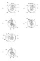
次に、本実施例に係るハンマ41とアンビル46の打撃動作を説明する前に、図6、7を用いて本発明のハンマとアンビルの基本構成と、その打撃動作原理を説明する。図6は、本発明の基本構成に係るハンマ151とアンビル156の形状を示す図であり、最もシンプルな形状のものである。この形状は本発明の第2の実施例に係る形状でもある。ハンマ151は、円筒形の本体部分151bから軸方向に突出する1組の突出部、即ち突出部152と突出部153が形成される。本体部分151bの前方側、中央には、アンビル156の後方に形成された嵌合穴(図示せず)に嵌合する嵌合軸151aが形成され、ハンマ151とアンビル156は相対的に1回転未満(360度未満)の所定角度だけ回転可能なように連結される。突出部152は打撃爪として作用するもので、円周方向の両側に平面状の打撃面152aと152bが形成される。また、ハンマ151には、突出部152との回転バランスを取るための突出部153が形成される。突出部153は、回転バランスをとるための錘部として機能するため、打撃面は形成されない。
Next, before describing the hammering operation of the
本体部分151bの後方側には、接続部分151dを介して円盤部151cが形成される。本体部分151bと円盤部151cの間の空間は、遊星歯車機構21のプラネタリーギヤ21bを配置するためのもので、円盤部151cにはプラネタリーギヤ21bの回転軸21cを保持するための貫通穴151fが形成される。図示していないが、本体部分151bの円盤部151cに面する側にもプラネタリーギヤ21bの回転軸21cを保持するための保持穴が形成される。
A
アンビル156は、円筒形の本体部分156bの前端側に先端工具を装着するための装着穴156aが形成され、本体部分156bの後方側には本体部分156bから半径方向外側に突出する2つの突出部157と158が形成される。突出部157は、被打撃面157aと157bを有する打撃爪であり、突出部158が被打撃面をもたない錘部である。突出部157は、突出部152と衝突するように構成されるため、その外径は突出部152の外径と同じに構成される。しかしながら突出部153と158は共に錘として作用させるだけであって、どの部位にも衝突させないために、お互いが干渉しない位置や大きさに形成し配置することが重要である。また、ハンマ151とアンビル156の相対的な回転角をできるだけ多く取るために(但し、最大でも1回転未満である)、突出部153及び158の半径方向の厚さを小さくして円周方向の長さを大きくすることによって、突出部152と157との回転バランスをとれるように形成される。相対的な回転角を大きく設定することにより、ハンマをアンビルに衝突させるときのハンマの加速区間(助走区間)を大きく取ることができ、大きなエネルギーにて打撃することができる。
The
図7は、ハンマ151及びアンビル156の使用状態における一回転の動きを6段階で示した断面図である。断面は軸方向と垂直面であって、打撃面152a(図6)を含む断面である。図7(1)の状態において、先端工具からうける締め付けトルクが小さいうちは、アンビル156はハンマ151から押されることにより反時計回りに回転する。しかしながら、締め付けトルクが大きくなってハンマ151から押される力だけでは回転できなくなった場合には、ハンマ151によってアンビル156を叩くため、ハンマ151を矢印161の方向に逆回転させるべく、モータ3の逆回転を開始する。(1)で示す状態においてモータ3の反転を開始し、それによってハンマ151の突出部152を矢印161の方向に回転させ、さらにモータ3を逆回転させて、(2)に示すように突出部152は突出部158の外周側を通って矢印162の方向に加速されながら回転する。ここで、突出部158の外径Ra1は、突出部152の内径Rh1よりも小さく構成され、両者は衝突しない。同様に、突出部157の外径Ra2は、突出部153の内径Rh2よりも小さく構成され、両者は衝突しない。このような位置関係に構成すれば、ハンマ151とアンビル156との相対回転角を180度より大きく構成することができ、アンビル156に対してハンマ151の十分な量の反転角を確保することができる。
FIG. 7 is a cross-sectional view showing the movement of one rotation in the use state of the
ハンマ151がさらに逆回転して、矢印163aに示すように図7(3)の位置(逆回転の停止位置)に到達したら、モータ3の回転を一定時間休止し、その後モータ3の矢印163bの方向(正回転方向)への回転を開始する。尚、ハンマ151を逆回転させた際に、アンビル156に衝突しないように、停止位置において確実にハンマ151を停止させることが重要である。ハンマ151の停止位置を、アンビル156と衝突する位置のどの程度前に設定するかは任意であるが、必要とされる締め付けトルクの関係からできるだけ大きくすると良い。また、停止位置は毎回同じ位置とする必要はなく、締め付け初期段階では逆回転角を小さくして、締め付けが進むにつれて逆回転角を大きく設定するように構成しても良い。このように停止位置を可変にすれば逆回転に要する時間を最小に設定できるので、短い時間で迅速に打撃動作を行うことができる。
When the
そして、図7(4)の位置を矢印164の方向に通過しながらさらにハンマ151を加速させ、加速中の状態のまま図7(5)に示す位置にて突出部152の打撃面152aは、アンビル156の被打撃面157aに衝突する。この衝突の結果、アンビル156には強力な回転トルクが伝達され、アンビル156は矢印166で示す方向に回転する。図7(6)の位置は、図7(1)で示した状態から、ハンマ151とアンビル156の双方が所定角度分だけ回転した状態であり、再び図7(1)の状態から図7の(5)に至る動作を繰り返すことによって、被締結部材を適正トルクになるまで締め付けを行う。
Then, the
以上のように、本発明に係るハンマ151とアンビル156では、モータ3を逆回転させる駆動モードを用いることによって、打撃機構としてハンマ151とアンビル156だけのきわめてシンプルな構成で、インパクト工具を実現することができる。尚、この構成の打撃機構においては、モータ3の駆動モードの設定によって、ドリルモードとして回転させることもできる。例えば、ドリルモードにおいては、図7(5)の状態からモータ3を回転させてハンマ151を正方向に回転させるだけで図7(6)のようにアンビル156を追従して回転させることが可能であるので、これを繰り返すことにより締め付けトルクが小さくて済むネジやボルト等の被締結部材を高速で締め付けることができる。
As described above, with the
さらに、本実施例に係るインパクト工具1においては、モータ3としてブラシレスDCモータを用いているため、電流検出回路59(図5参照)からモータ3に流れる電流値を求めて、電流値が所定の値よりも大きくなった状態を検出して、演算部51がモータ3を停止させることによって、所定トルクまで締め付けた後に動力伝達を遮断させる、いわゆるクラッチ機構を電子的に実現することができる。従って、本発明の本実施例に係るインパクト工具1においては、ドリルモード時のクラッチ機構をも実現することができ、簡単な構成の打撃機構にてクラッチ無しのドリルモード、クラッチ付きのドリルモード、インパクトモードを有するマルチユースの締付け工具を実現できる。
Furthermore, since the
次に図8、9を用いて、図1、2に示した打撃機構40の詳細構造を説明する。図8は、本発明の第1の実施例に係るハンマ41とアンビル46の形状を示す斜視図であり、ハンマ41は斜め前方から、アンビル46は斜め後方か見た図である。図9はハンマ41とアンビル46の形状を示す斜視図であり、ハンマ41は斜め後方から見た図であり、アンビル46は斜め前方からみた部分図である。ハンマ41は、円柱形の本体部分41bから径方向に突出する2つの羽根部41cと41dが形成される。羽根部41cと41dには、それぞれ軸方向に突出する突出部が形成されるが、図6で示した基本構成(第2の実施例)と異なることは、羽根部41cと41dのそれぞれに一組ずつの打撃部と錘部が形成されることである。
Next, the detailed structure of the
羽根部41c側は、外周部が扇状に広がるように形成されとともに、外周部から軸方向前方に突出する突出部42が形成される。この扇状に広がる部分と突出部42が打撃部(打撃爪)として機能と同時に、錘部としての機能を果たす。突出部42には円周方向の両側には打撃面42aと42bが形成される。打撃面42aと42bは、共に平面に形成されたもので、アンビル46の後述する被打撃面と良好に面接触するように適度な角度がつけられる。一方、羽根部41dは外周部が扇状に広がるように形成され、扇状に広がる形状によりその部分の質量が大きくなり錘部として良好な作用を果たす。また羽根部41dの径方向中央付近から軸方向前方に突出する突出部43が形成される。突出部43は打撃部(打撃爪)として作用するもので、円周方向の両側には打撃面43aと43bが形成される。打撃面43aと43bは、共に平面状に形成されたもので、アンビル46の後述する被打撃面と良好に面接触するように、円周方向に適度な角度がつけられる。
On the
本体部分41bの軸心付近、前方側にはアンビル46の嵌合穴46fと嵌合される嵌合軸41aが形成される。本体部分41bの後方側には遊星キャリヤの機能を有するように2つの円盤部44a、44bと円周方向の2箇所においてこれらを接続する接続部44cが形成される。円盤部44a、44bの円周方向のそれぞれ2箇所には、貫通穴44dが形成され、円盤部44a、44bの間に2つのプラネタリーギヤ21b(図3参照)が配置され、プラネタリーギヤ21bの回転軸21c(図3参照)が貫通穴44dに装着される。円盤部44bの後方側には円筒形に延びる円筒部44eが形成される。円筒部44eの外周側はベアリング16bの内輪にて保持される。また、円筒部44eの内側の空間44fにはサンギヤ21a(図3参照)が配置される。尚、図8及び図9に示すハンマ41とアンビル46とは、金属の一体構造にて製造すると強度的にも重量的にも好ましい。
Near the axis of the
アンビル46は、円柱形の本体部分46bから径方向に突出する2つの羽根部46cと46dが形成される。羽根部46cの外周付近には軸方向後方に突出する突出部47が形成される。突出部47の円周方向両側には被打撃面47a及び47bが形成される。一方、羽根部46dの径方向中央付近には軸方向後方に突出する突出部48が形成される。突出部48の円周方向両側には被打撃面48a及び48bが形成される。ハンマ41が正回転(ネジ等を締め付ける回転方向)するときには、打撃面42aが被打撃面47aに当接し、同時に打撃面43aが被打撃面48aに当接する。また、ハンマ41が逆回転(ネジ等をゆるめる回転方向)するときには、打撃面42bが被打撃面47bに当接し、同時に打撃面43bが被打撃面48bに当接する。この当接するのは同時となるように突出部42、43、47、48の形状が決定される。
The
このように、図8、9に示すハンマ41及びアンビル46によれば、回転する軸心を基準に対称な2箇所にて打撃が行われるので打撃時のバランスが良く、打撃時にインパクト工具1が振られにくく構成できる。また、打撃面は突出部の円周方向両側にそれぞれ設けられるので、正回転だけでなく逆回転時にもインパクト動作が可能になるので、使いやすいインパクト工具を実現できる。さらに、ハンマ41でアンビル46を打撃する方向は、円周方向のみであってアンビル46を軸方向、前方に叩かないので、先端工具を必要以上に被締結部材を押しつけることもなく、木材に木ねじ等を締め込む際に有利である。
As described above, according to the
次に図10を用いて図8、9に示したハンマ41及びアンビル46の打撃動作を説明する。基本的な動作は図7で説明した動作と同じであり、違いは打撃時に1箇所でなくほぼ軸対称な2箇所の打撃面にて同時に打撃されることである。また、図10で示す断面図は図3のA−A部の断面であり、この断面からハンマ41から軸方向に突出する突出部42、43と、アンビル46から軸方向に突出する突出部47、48の位置関係が理解できるであろう。締め付け動作時(正回転時)のアンビル47の回転方向は反時計回りである。
Next, the hammering operation of the
図10(1)は、ハンマ41がアンビル46に対して最反転位置まで逆回転した状態である(図7(3)の状態に相当)。この状態からハンマ41をアンビル46に対して衝突させるべく、矢印91の方向(正方向)に加速させる。そして、図10(2)のように突出部42は突出部48の外周側を通過し、同時に突出部43は突出部47の内周側を通過する。このように、双方の通過を可能とするために、突出部42の内径RH2は、突出部48の外径RA1よりも大きく構成され、両者は衝突しない。同様に、突出部43の外径RH1は、突出部47の内径RA2よりも小さく構成され、両者は衝突しない。このような位置関係に構成すれば、ハンマ41とアンビル46との相対回転角を180度より大きく構成することができ、アンビル46に対してハンマ41の十分な量の反転角が確保でき、この反転角がハンマ41をアンビル46に打撃する前の加速区間とすることができる。
FIG. 10A shows a state in which the
次に、図10(3)の状態までハンマ41が正回転すると突出部42の打撃面42aは、突出部47の被打撃面47aに衝突する。同時に、突出部43の打撃面43aは突出部48の被打撃面48aに衝突する。このように、回転軸に対して反対側の2箇所にて衝突することによりアンビル46に対してバランスの良い打撃を行うことができる。この打撃の結果、図10(4)に示すようにアンビル46は、矢印94の方向に回転することになり、この回転によって被締結材の締め付けが行われる。尚、ハンマ41には、径方向の同心位置(RH2以上、RH3以下の位置)において唯一の突起である突出部42を有し、同心位置(RH1以下の位置)において第3の唯一の突起である突出部43を有する。また、アンビル46は、径方向の同心位置(RA2以上、RA3以下の位置)において唯一の突起である突出部47を有し、同心位置(RA1以下の位置)において唯一の突起である突出部48を有する。
Next, when the
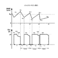
次に、本実施例に係るインパクト工具1の駆動方法について説明する。本実施例に係るインパクト工具1においては、アンビル46とハンマ41が、相対的に360度未満の回転角で回転可能なように形成される。従って、ハンマ41はアンビル46に対して1回転以上の相対的回転ができないため、その回転制御も特有のものになる。図11は、インパクト工具1の運転時のトリガ信号、インバータ回路の駆動信号、モータ3の回転速度、ハンマ41とアンビル46の打撃状況を示す図である。各グラフにおいて横軸は時間であり、各グラフのタイミングを比較できるように横軸を合わせて記載している。
Next, a driving method of the
本実施例に係るインパクト工具1において、インパクトモードにおける締め付け作業の場合は、最初連続駆動モードで高速に締め付けを行い、必要な締め付けトルク値が大きくなったらパルスモード(1)に切り替えて締め付けを行い、必要な締め付けトルク値がさらに大きくなったらパルスモード(2)に切り替えて締め付けを行う。図11の時間T1からT2における連続駆動モードでは、演算部51はモータ3を目標回転数に基づく制御を行う。このためモータ3は矢印85aで示す目標回転数に達するまでモータを加速させる。その後、アンビル46に取り付けられた先端工具からの締め付け反力が大きくなると、モータ3の回転速度が徐々に落ちてくる。そこで、その回転速度の落ち込みをモータ3に供給される電流値で検出して、時間T2でパルスモード(1)による回転駆動モードに切り替える。
In the
パルスモード(1)は、モータ3を連続的に駆動するのではなく断続的に駆動するモードであり、「休止→正回転駆動」を複数回繰り返すようにパルス状に駆動する。ここで、「パルス状に駆動する」とは、インバータ回路52に加えるゲート信号を脈動させることにより、モータ3に供給される駆動電流を脈動させ、それによってモータ3の回転数又は出力トルクを脈動させるように駆動制御することである。この脈動は、時間T2からT21まではモータへ供給される駆動電流OFF(休止)、時間T21からT3まではモータの駆動電流ON(駆動)、時間T3からT31までは駆動電流OFF(休止)、時間T31から時間T4までは駆動電流ONというような、大きな周期(例えば数十Hz〜百数十Hz程度)で駆動電流のON−OFFを繰り返すことによって発生される。尚、駆動電流ON状態の時にはモータ3の回転数制御のためにPWM制御が行われるが、そのデューティ比制御の周期(通常数キロHz)に比べると、脈動させる周期は十分小さい。
The pulse mode (1) is a mode in which the
図11の例では、T2から一定の時間モータ3への駆動電流の供給を休止して、モータ3の回転速度が矢印85bに低下した後に、演算部51(図5参照)は駆動信号83aを制御信号出力回路53に送ることによりモータ3にパルス状の駆動電流(駆動パルス)が供給され、モータ3を加速させる。尚、この加速時の制御は、必ずしもデューティ比100%で駆動という意味ではなく、100%未満のデューティ比で制御する事もありうる。次に、矢印85cの地点においてハンマ41がアンビル46に強く衝突することにより、矢印88aで示すように打撃力が与えられる。打撃力が与えられると再び、所定期間モータ3への駆動電電流の供給を休止し、モータの回転速度が矢印85bで示すように低下した後に、演算部51は駆動信号83bを制御信号出力回路53に送ることによりモータ3を加速させる。すると、矢印85eの地点においてハンマ41がアンビル46に強く衝突することにより、矢印88bで示すように打撃力が与えられる。パルスモード(1)においては、上述したモータ3の「休止→正回転駆動」を繰り返す断続的な駆動が1回又は複数回繰り返されるが、より高い締め付けトルクが必要になったらその状態を検出し、パルスモード(2)による回転駆動モードに切り替える。高い締め付けトルクが必要になったか否かの判定は、例えば矢印88bで示す打撃力が与えられた際のモータ3の回転数(矢印85eの前後)を用いて判断することができる。
In the example of FIG. 11, by resting the supply of the drive current from T 2 to a certain time the
パルスモード(2)は、モータ3を断続的に駆動し、パルスモード(1)と同様にパルス状にモータ3を駆動するモードであるが、「休止→逆回転駆動→休止(停止)→正回転駆動」を複数回繰り返すように駆動する。つまりパルスモード(2)においては、モータ3の正回転駆動だけでなく逆回転駆動をも加わるために、ハンマ41をアンビル46に対して十分な相対角だけ逆回転させた後に、ハンマ41を正回転方向に加速させて勢いよくアンビル46に衝突させる。このようにハンマ41を駆動することにより、アンビル46に強い締め付けトルクを発生させるものである。
The pulse mode (2) is a mode in which the
図11の例では時間T4でパルスモード(2)に切り替わると、モータ3の駆動を一時休止させて、その後負の方向の駆動信号84aを制御信号出力回路53に送ることによりモータ3を逆回転させる。正転、逆転を行う際には、制御信号出力回路53から各スイッチング素子Q1〜Q6に出力する各駆動信号(オンオフ信号)の信号パターンを切り替えることにより実現される。モータ3が所定の回転角分だけ逆回転したら、モータ3の駆動を一時休止させて正回転駆動を開始する。このため、正の方向の駆動信号84bを御信号出力回路53に送る。尚、インバータ回路52を用いた回転駆動においては、駆動信号をプラス側又はマイナス側に切り替えるものではないが、図11ではどちら方向へ回転駆動するか容易に理解できるように、駆動信号を+及びー方向に分けて模式的に表現した。
When switched to the pulse mode (2) in T 4 time example of FIG. 11, by pause the driving of the
モータ3の回転速度が最大速度に達する付近でハンマ41はアンビル46に衝突する(矢印86c)。この衝突によりパルスモード(1)で発生する締め付けトルク(88a、88b)に比べて格段に大きい締め付けトルク89aが発生する。このように衝突が行われると矢印86cから86dに至るようにモータ3の回転数が低下する。尚、矢印89aに示す衝突を検出した瞬間にモータ3への駆動信号を停止する制御をしても良く、その場合は締結対象がボルトやナット等の場合は打撃後に作業者の手に伝わる反動が少なくて済む。本実施例のように衝突後もモータ3に駆動電流を流すことにより作業者への反力が連続駆動モードに比較して小さく、中負荷状態での作業に適している。また、締め付け速度が速く、パルス強モードと比較して電力消費が少なくて済むという効果が得られる。その後、同様にして、「休止→逆回転駆動→休止(停止)→正回転駆動」を所定回数だけ繰り返すことにより強い締め付けトルクでの締め付けが行われ、時間T7において作業者がトリガ操作を解除することによってモータ3が停止し、締め付け作業が完了する。尚、作業の完了は作業者によるトリガ操作の解除だけでなく、打撃衝撃検出センサ56(図5参照)の出力を元に、演算部51が設定された締め付けトルクでの締め付けが完了したと判断したらモータ3の駆動を停止するように制御しても良い。
The
以上説明したように、本実施例においては締め付けトルクが少なくてすむ締め付け初期段階は連続駆動モードで回転駆動し、締め付けトルクが大きくなるにつれて正転のみの断続駆動によるパルスモード(1)で締め付けを行い、締め付けの最終段階においては、モータ3の正転及び逆転による断続駆動によるパルスモード(2)によって強力に締め付けを行う。尚、パルスモード(1)とパルスモード(2)だけを使って駆動するように構成しても良い。また、パルスモード(1)を設けないで、連続駆動モードからパルスモード(2)に直接移行する制御も可能である。パルスモード(2)ではモータの正回転と逆回転を交互に行うため、締め付け速度が、連続駆動モードやパルスモード(1)よりも大幅に遅くなる。このように締め付け速度が急に遅くなると、周知の回転打撃機構を有するインパクト工具に比べて打撃動作に移行する際の違和感が大きくなるので、連続駆動モードからパルスモード(2)への移行にあたり、パルスモード(1)を介在させた方が操作感が自然な感じとなる。さらに、可能な限り連続駆動モードやパルスモード(1)で締め付けを行うことにより、締め付け作業時間の短縮化を図ることができる。
As described above, in this embodiment, the initial stage of tightening which requires less tightening torque is rotationally driven in the continuous drive mode, and as the tightening torque increases, tightening is performed in the pulse mode (1) with intermittent driving only in the forward direction. In the final stage of tightening, the tightening is performed strongly by the pulse mode (2) by intermittent driving by forward and reverse rotation of the
次に、図12〜図16を用いて本発明に係るインパクト工具1の制御手順を説明する。図12は、本発明の実施例に係るインパクト工具1の制御手順を示すフローチャートである。インパクト工具1は、作業者による作業の開始に先立ち、トグルスイッチ32(図2参照)を用いてインパクトモードが選択されたか否かを判定する(ステップ101)。インパクトモードが選択された場合はステップ102に進み、選択されていない場合、即ち通常のドリルモードの場合はステップ110に進む。
Next, the control procedure of the
インパクトモードにおいては、演算部51はトリガスイッチ8がONされたか否かを判定し、ONされた(トリガ操作部8aが引かれた)場合は、図11に示したように連続駆動モードによりモータ3を起動し(ステップ103)、トリガ操作部8aの引き量に応じてインバータ回路52のPWM制御を開始する(ステップ104)。そして、モータ3に供給されるピーク電流が上限値のpを超えないように制御しながらモータ3の回転を加速させる。次に、起動してからtミリ秒経過した後のモータ3に供給される電流値Iを、電流検出回路59(図5参照)の出力を用いて検出する。検出された電流値Iがp1アンペアを超えていなかったらステップ104に戻り、超えていたらステップ108に進む(ステップ107)。次に、検出された電流値Iがp2アンペアを超えているか否かを判定する(ステップ108)。
In the impact mode, the
ステップ108において、検出された電流値Iがp2[A]を超えていなかったら、即ち、p1<I<p2の関係にあったら図14で示すパルスモード(1)の手順を実行してからステップ109に進み(ステップ120)、検出された電流値Iがp2[A]を超えていたらパルスモード(1)の手順を実行することなく直接ステップ109に進む。ステップ109において、トリガスイッチ8がオンになっているかを判定し、OFFにされた場合はステップ101に戻り、ON状態が継続されている場合は図16で示すパルスモード(2)の手順を実行してからステップ101に戻る。
In
ステップ101でドリルモードが選択されている場合は、ドリルモード110が実行されるが、その制御はステップ102から107の制御と同様である。そして、ステップ107のp1として、電子クラッチでの制御電流あるいは、モータ3のロック直前による過電流状態を検出してモータ3を停止させる(ステップ111)ことにより、ドリルモードを終了し、ステップ101に戻る。
When the drill mode is selected in
ここで、図13を用いてステップ107、108におけるモード移行の判定手順を説明する。上側のグラフは経過時間とモータ3の回転数との関係を示すもので、下側のグラフはモータ3に供給される電流値と時間の関係を示すもので、上下のグラフの時間軸は同じにしている。左側のグラフにおいて、時間TAにおいてトリガスイッチが引かれると(図12のステップ102に相当)、モータ3が矢印113aのように起動されて加速される。この加速の際には、矢印114aで示すように最大電流値pが制限された状態での定電流制御がされる。モータ3の回転数が所定の回転数に到達すると(矢印113b)、矢印114bに示すように加速時電流から定常時電流になるため、電流値が減少する。この後、ネジやボルト等の締結が進行するに従って、締結部材からの受ける反力が増加すると、矢印113cに示すようにモータ3の回転数が徐々に低下すると共に、モータ3に供給される電流値が増加する。そしてモータ3の起動からtミリ秒経過した後に電流値が判定され、矢印114cに示すように、p1<I<p2の関係にある場合はステップ120で示すように後述するパルスモード(1)の制御に移行する。
Here, the procedure for determining the mode transition in
右側のグラフにおいて、時間TBにおいてトリガスイッチが引かれると(図12のステップ102に相当)、モータ3が矢印115aのように起動されて加速される。この加速の際には、矢印116aで示すように最大電流値pが制限された状態での定電流制御がされる。モータ3の回転数が所定の回転数に到達すると(矢印115b)、矢印116bに示すように加速時電流から定常時電流になるため、電流値が減少する。この後、ネジやボルト等の締結が進行するに従って、締結部材からの受ける反力が増加すると、矢印115cに示すようにモータ3の回転数が徐々に低下すると共に、モータ3に供給される電流値が増加する。本例では、締結部材からの受ける反力が急激に増加したため、矢印116cで示すようにモータ3の回転数の低下が大きく、また、電流値の上昇度合いが大きい。そしてモータ3の起動からtミリ秒経過した後の電流値が116cで示すように、p2<Iの関係にあるため、ステップ140に示すように図16で示すパルスモード(2)の制御に移行する。
In the right side of the graph, when the trigger switch is pulled at time T B (corresponding to step 102 of FIG. 12), the
通常ネジやボルト等の締め付け作業においては、ネジやボルトの加工精度のばらつき、被締結材の状態、木材の節や木目などの材質のばらつき等により、必要とされる締め付けトルクが一定でないことが多い。そのため連続駆動モードだけで締め付け完了直前まで一気に締め付けることができてしまう場合がありうる。このような場合は、パルスモード(1)における締め付けをスキップして、より締め付けトルクの高いパルスモード(2)による締め付けに移行させると短時間で効率よく締め付け作業を完了させることができる。 Normally, when tightening screws and bolts, the required tightening torque may not be constant due to variations in the processing accuracy of screws and bolts, the condition of the material to be fastened, and variations in materials such as wood nodes and grain. Many. Therefore, it may be possible to perform tightening at a stretch until just before the tightening is completed only in the continuous drive mode. In such a case, the tightening operation can be completed efficiently in a short time by skipping the tightening in the pulse mode (1) and shifting to the tightening in the pulse mode (2) having a higher tightening torque.
次に図14のフローチャートを用いてパルスモード(1)でのインパクト工具の制御手順を説明する。パルスモード(1)に移行した場合、まず所定の休止期間をおいてから、ピーク電流をp3アンペア以下と制限し(ステップ121)、所定の時間、即ちTミリ秒だけモータ3に正転電流を供給することによってモータ3を回転させる(ステップ122)。次に、時間Tミリ秒経過後にそのときのモータ3の回転数N1n(但し、n=1、2、・・)[rpm]を検出する(ステップ123)。次に、モータ3へ供給する駆動電流をOFFにし、モータ3の回転数が、N1nからN2n(=N1n/2)に低下するまで減速するまでに要する時間t1nを測定する。次に、t2n=X−t1nよりt2nを求め、このt2nの期間だけモータ3に正転電流を加え(ステップ126)、ピーク電流をp3アンペア以下に押さえてモータ3を加速させる。次に、t2n時間経過後にモータ3の回転数N1(n+1)が、パルスモード(2)に移行するための閾値回転数Rth以下か否かを判定し、Rth以下である場合はパルスモード(1)の処理を終了して図12のステップ120に戻り、Rth以上である場合はステップ124に戻る(ステップ128)。
Next, the control procedure of the impact tool in the pulse mode (1) will be described using the flowchart of FIG. When the mode is changed to the pulse mode (1), first, after a predetermined rest period, the peak current is limited to p3 amperes or less (step 121), and the forward current is applied to the
図15は、図14に示すフローチャートの手順を実行中のモータ3の回転数と経過時間の関係、及び、モータ3に供給される電流と経過時間の関係を示すグラフである。最初に時間Tだけモータ3に駆動電流132が供給される。駆動電流はピーク電流をp3アンペア以下と制限されるため、矢印132aに示すように加速時の電流が制限され、その後、モータ3の回転数が上がるにつれて電流値が矢印132bのように低下する。時間T1において、モータ3の回転数がN11に到達したのが測定されると、N21=N11/2からモータ3の回転を開始する回転数N21が計算によって算出される。回転数N11は、例えば10,000rpmである。モータ3の回転数がN21に低下すると、駆動電流133が供給されモータ3が再び加速される。駆動電流133を流す時間t2nは、t2n=X−t1nにて決定される。同様にして、時間2X、3Xにおいて同様の制御を行うが、締め付け反力が大きくなるにつれてモータ3の回転数上昇度合いが低下し、時間4Xにおいて回転数N14は閾値回転数Rth以下となってしまう。この時点で、パルスモード(1)の処理が終了し、パルスモード(2)の処理へと移行することになる。
FIG. 15 is a graph showing the relationship between the rotational speed of the
次に図16のフローチャートを用いてパルスモード(2)でのインパクト工具の制御手順を説明する。まず、モータ3に供給する駆動電流をオフにして5ミリ秒待機する(ステップ141)。次に、モータを−3000rpmで回転させるように、逆転電流をモータ3に供給する(ステップ142)。ここで、‘マイナス’とは作業中の回転方向とは逆方向に3000rpmで回転させるという意味である。次に、モータ3の回転数が、−3000rpmに到達したら、モータ3に供給する電流をオフにして、5ミリ秒待機する(ステップ143)。ここで5ミリ秒待機するのはいきなりモータ3を逆方向に逆転させると、インパクト工具本体が振られてしまう恐れがあるためである。また、この待機時において電力の消費がないので省エネルギーを達成できるからである。次に、モータ3を正回転方向に回転させるべく、正転電流をオンにする(ステップ144)。正転電流をオンにしてから95ミリ秒後にモータ3に供給する電流をオフにするが、この電流をオフにする前にハンマ41がアンビル46に衝突する(打撃する)ことにより、先端工具に強い締め付けトルクが発生する(ステップ145)。その後、トリガスイッチのオン状態が維持されているかを検出し、オフの状態であればモータ3の回転を停止してパルスモード(2)の処理を終了し、図12のステップ140に戻る(ステップ147、148)。ステップ147で、トリガスイッチ8がオンの状態であればステップ141に戻る(ステップ147)。
Next, the control procedure of the impact tool in the pulse mode (2) will be described using the flowchart of FIG. First, the drive current supplied to the
以上説明したように、本実施例によれば相対回転角が1回転未満のハンマとアンビルを用いて、モータを連続回転、正方向のみの断続回転、正方向及び逆方向の断続回転を行うことによって、効率的に締結部材を締結することができる。また、ハンマとアンビルの形状をシンプルな構造にすることができたので、インパクト工具の小型化及びコストダウンが実現できる。 As described above, according to the present embodiment, using a hammer and anvil having a relative rotation angle of less than one rotation, the motor is continuously rotated, intermittent rotation only in the positive direction, and intermittent rotation in the forward direction and the reverse direction. Thus, the fastening member can be fastened efficiently. Moreover, since the shape of the hammer and the anvil can be made simple, the impact tool can be reduced in size and cost can be reduced.
以上、本発明を示す実施例に基づき説明したが、本発明は上述の実施例に限定されるものではなく、その趣旨を逸脱しない範囲内で種々の変更が可能である。例えば、本実施例ではモータとしてブラシレスDCモータを用いた例を説明したが、これに限定されず、正方向及び逆方向に駆動できる他の種類のモータであっても良い。 As mentioned above, although demonstrated based on the Example which shows this invention, this invention is not limited to the above-mentioned Example, A various change is possible within the range which does not deviate from the meaning. For example, in the present embodiment, an example in which a brushless DC motor is used as the motor has been described. However, the present invention is not limited to this, and other types of motors that can be driven in the forward direction and the reverse direction may be used.
また、アンビルとハンマの形状は任意であり、アンビルとハンマが相対的に連続回転できない(乗り越えながら回転できず)構造とし、相対的に360度未満の所定の回転角を確保し、打撃面、被打撃面を形成すれば良い。例えば、ハンマとアンビルの突出部が軸方向に突出するのではなく、円周方向にも突出するように構成しても良い。さらに、ハンマとアンビルの突出部は、必ずしも外部に凸となる突出部だけに限られずに、なんらかの形状にて打撃面、被打撃面を形成できれば良いので、ハンマ又はアンビルの内部に突出する突出部(つまり凹部)であっても良い。また、打撃面、被打撃面は必ずしも平面に限られずに、曲面であっても、その他の良好に打撃及び被打撃される形状であれば良い。 In addition, the anvil and the hammer can have any shape, the anvil and the hammer cannot be relatively continuously rotated (cannot be rotated while riding over), ensure a predetermined rotation angle of less than 360 degrees, What is necessary is just to form a to-be-struck surface. For example, you may comprise so that the protrusion part of a hammer and an anvil may protrude not in the axial direction but in the circumferential direction. Further, the protrusions of the hammer and the anvil are not necessarily limited to the protrusions that protrude outward, and it is sufficient that the striking surface and the striking surface can be formed in any shape. (That is, a recess). Further, the striking surface and the striking surface are not necessarily limited to a flat surface, but may be a curved surface as long as it has a shape that can be hit and striked well.
1 インパクト工具 3 モータ
3a (モータの)回転子 3b (モータの)固定子
3c (モータの)永久磁石 3d 絶縁部材
3e (モータの)コイル 5 ケース
6 ハウジング 6a (ハウジングの)胴体部
6b (ハウジングの)グリップ部 6c (ハウジングの)バッテリ保持部
7 基板 8 トリガスイッチ 8a トリガ操作部
9 制御回路基板 10 スイッチング素子 11 カバー
12 LEDライト 14 正逆切替レバー
15 スリーブ 15a スプリング 15b ワッシャ
15c 止め輪 16a メタルベアリング 16b ベアリング
17a、17b ベアリング 18 冷却ファン
18a (冷却ファンの)貫通穴 18b (冷却ファンの)円筒部
18c (冷却ファンの)フィン 18d (冷却ファンの)開口部
19 (モータの)回転軸
20 ネジボス 21 遊星歯車減速機構
21a サンギヤ 21b プラネタリーギヤ
21c 回転軸 21d アウターギヤ 22 インナカバー
23 Oリング 24 ボール
26a、26b 空気取入口 26c スリット
30 バッテリパック 30a リリースボタン 31 制御パネル
32 トグルスイッチ(インパクトモード/ドリルモード切替スイッチ)
33 ベルトフック 34 ストラップ
40 打撃機構 41 ハンマ 46 アンビル
50 制御部 51 演算部 52 インバータ回路
53 制御信号出力回路 54 回転子位置検出回路
55 回転数検出回路 56 打撃衝撃検出センサ
57 打撃衝撃検出回路 59 電流検出回路
60 スイッチ操作検出回路 61 印加電圧設定回路
62 回転方向設定回路
151 ハンマ 151a 嵌合軸 151b 本体部分
151c 円盤部 151d 接続部分 151f 貫通穴
152 突出部 152a、152b 打撃面 153 突出部
156 アンビル 156a 装着穴 156b 本体部分
157 突出部 157a、157b 被打撃面 158 突出部
1
3c (Motor)
18a Through
26a, 26b Air intake
33
40
60 Switch
Claims (8)
前記打撃機構は、打撃面を有するハンマと、被打撃面を有し前記ハンマにより打撃される出力軸を有し、前記ハンマは連続回転が可能であり、前記ハンマと前記出力軸は相互に360度未満の相対回転だけが可能であり、
締め付け初期段階では前記ブラシレスモータを正転方向に連続駆動させ、負荷が大きくなると前記ブラシレスモータの回転数を脈動させ、更に負荷が大きくなると前記ブラシレスモータの正転と逆転を繰り返すように駆動することにより締め付けを行うことを特徴とするインパクト工具。 In a brushless motor, a striking mechanism that is connected to the brushless motor and rotatably supported by the brushless motor, and an impact tool that strikes a tip tool by the output of the striking mechanism,
The striking mechanism includes a hammer having a striking surface, an output shaft which is struck by the hammers have a struck surface, the hammer is capable of continuous rotation, the output shaft and the hammer 360 to each other Only relative rotation of less than degrees is possible,
In the initial tightening stage, the brushless motor is continuously driven in the forward rotation direction, and when the load increases, the rotation speed of the brushless motor is pulsated, and when the load further increases, the brushless motor is driven to repeat forward rotation and reverse rotation. Impact tool characterized by tightening with
前記ドリル制御においては正転の連続駆動のみで前記ブラシレスモータを駆動し、
前記インパクト制御においては前記ブラシレスモータの正転方向への連続駆動と、回転数を脈動させる駆動と、正転と逆転を繰り返す駆動を切り替えながら締め付けを行うことを特徴とする請求項1に記載のインパクト工具。 The impact tool has two control levels, drill control and impact control,
In the drill control, the brushless motor is driven only by forward continuous driving,
2. The impact control according to claim 1, wherein tightening is performed while switching between continuous driving in the forward direction of the brushless motor , driving that pulsates the rotational speed, and driving that repeats normal rotation and reverse rotation . Impact tool.
前記制御部が前記ブラシレスモータの回転方向及び回転速度を制御することを特徴とする請求項4に記載のインパクト工具。 An inverter circuit for supplying a predetermined drive current to the brushless motor, and a controller for controlling the drive of the inverter circuit;
The impact tool according to claim 4, wherein the control unit is characterized that you control the rotational direction and the rotational speed of the brushless motor.
前記ドリル制御において、検出された電流値が所定の電流閾値以上になった場合に、前記制御部は前記ブラシレスモータを停止させることを特徴とする請求項2〜6のいずれか一項に記載のインパクト工具。 A current detection circuit for detecting a current flowing in the brushless motor;
The said control part stops the said brushless motor when the detected electric current value becomes more than a predetermined electric current threshold value in the said drill control, The Claim 2 characterized by the above-mentioned. Impact tool.
前記ドリル制御において、モータの回転を停止させるトルク値を設定するための複数段の設定位置を前記切替ダイヤルに設けたことを特徴とする請求項7に記載のインパクト工具。 A switching dial for switching between the drill control and the impact control is provided,
The impact tool according to claim 7 , wherein, in the drill control, a plurality of setting positions for setting a torque value for stopping the rotation of the motor are provided on the switching dial.
Priority Applications (5)
| Application Number | Priority Date | Filing Date | Title |
|---|---|---|---|
| JP2009177115A JP5440766B2 (en) | 2009-07-29 | 2009-07-29 | Impact tools |
| CN201080033530.6A CN102470518B (en) | 2009-07-29 | 2010-07-29 | Percussion tool |
| PCT/JP2010/063233 WO2011013852A1 (en) | 2009-07-29 | 2010-07-29 | Impact tool |
| EP10745441A EP2459346A1 (en) | 2009-07-29 | 2010-07-29 | Impact tool |
| US13/387,742 US20130333910A1 (en) | 2009-07-29 | 2010-07-29 | Impact tool |
Applications Claiming Priority (1)
| Application Number | Priority Date | Filing Date | Title |
|---|---|---|---|
| JP2009177115A JP5440766B2 (en) | 2009-07-29 | 2009-07-29 | Impact tools |
Publications (2)
| Publication Number | Publication Date |
|---|---|
| JP2011031314A JP2011031314A (en) | 2011-02-17 |
| JP5440766B2 true JP5440766B2 (en) | 2014-03-12 |
Family
ID=42988481
Family Applications (1)
| Application Number | Title | Priority Date | Filing Date |
|---|---|---|---|
| JP2009177115A Expired - Fee Related JP5440766B2 (en) | 2009-07-29 | 2009-07-29 | Impact tools |
Country Status (5)
| Country | Link |
|---|---|
| US (1) | US20130333910A1 (en) |
| EP (1) | EP2459346A1 (en) |
| JP (1) | JP5440766B2 (en) |
| CN (1) | CN102470518B (en) |
| WO (1) | WO2011013852A1 (en) |
Families Citing this family (496)
| Publication number | Priority date | Publication date | Assignee | Title |
|---|---|---|---|---|
| US20070084897A1 (en) | 2003-05-20 | 2007-04-19 | Shelton Frederick E Iv | Articulating surgical stapling instrument incorporating a two-piece e-beam firing mechanism |
| US9060770B2 (en) | 2003-05-20 | 2015-06-23 | Ethicon Endo-Surgery, Inc. | Robotically-driven surgical instrument with E-beam driver |
| US11896225B2 (en) | 2004-07-28 | 2024-02-13 | Cilag Gmbh International | Staple cartridge comprising a pan |
| US8215531B2 (en) | 2004-07-28 | 2012-07-10 | Ethicon Endo-Surgery, Inc. | Surgical stapling instrument having a medical substance dispenser |
| US11998198B2 (en) | 2004-07-28 | 2024-06-04 | Cilag Gmbh International | Surgical stapling instrument incorporating a two-piece E-beam firing mechanism |
| US9072535B2 (en) | 2011-05-27 | 2015-07-07 | Ethicon Endo-Surgery, Inc. | Surgical stapling instruments with rotatable staple deployment arrangements |
| US10159482B2 (en) | 2005-08-31 | 2018-12-25 | Ethicon Llc | Fastener cartridge assembly comprising a fixed anvil and different staple heights |
| US11246590B2 (en) | 2005-08-31 | 2022-02-15 | Cilag Gmbh International | Staple cartridge including staple drivers having different unfired heights |
| US9237891B2 (en) | 2005-08-31 | 2016-01-19 | Ethicon Endo-Surgery, Inc. | Robotically-controlled surgical stapling devices that produce formed staples having different lengths |
| US7934630B2 (en) | 2005-08-31 | 2011-05-03 | Ethicon Endo-Surgery, Inc. | Staple cartridges for forming staples having differing formed staple heights |
| US11484312B2 (en) | 2005-08-31 | 2022-11-01 | Cilag Gmbh International | Staple cartridge comprising a staple driver arrangement |
| US7669746B2 (en) | 2005-08-31 | 2010-03-02 | Ethicon Endo-Surgery, Inc. | Staple cartridges for forming staples having differing formed staple heights |
| US20070106317A1 (en) | 2005-11-09 | 2007-05-10 | Shelton Frederick E Iv | Hydraulically and electrically actuated articulation joints for surgical instruments |
| US7845537B2 (en) | 2006-01-31 | 2010-12-07 | Ethicon Endo-Surgery, Inc. | Surgical instrument having recording capabilities |
| US11278279B2 (en) | 2006-01-31 | 2022-03-22 | Cilag Gmbh International | Surgical instrument assembly |
| US11793518B2 (en) | 2006-01-31 | 2023-10-24 | Cilag Gmbh International | Powered surgical instruments with firing system lockout arrangements |
| US8820603B2 (en) | 2006-01-31 | 2014-09-02 | Ethicon Endo-Surgery, Inc. | Accessing data stored in a memory of a surgical instrument |
| US8708213B2 (en) | 2006-01-31 | 2014-04-29 | Ethicon Endo-Surgery, Inc. | Surgical instrument having a feedback system |
| US20110024477A1 (en) | 2009-02-06 | 2011-02-03 | Hall Steven G | Driven Surgical Stapler Improvements |
| US8186555B2 (en) | 2006-01-31 | 2012-05-29 | Ethicon Endo-Surgery, Inc. | Motor-driven surgical cutting and fastening instrument with mechanical closure system |
| US11224427B2 (en) | 2006-01-31 | 2022-01-18 | Cilag Gmbh International | Surgical stapling system including a console and retraction assembly |
| US20120292367A1 (en) | 2006-01-31 | 2012-11-22 | Ethicon Endo-Surgery, Inc. | Robotically-controlled end effector |
| US7753904B2 (en) | 2006-01-31 | 2010-07-13 | Ethicon Endo-Surgery, Inc. | Endoscopic surgical instrument with a handle that can articulate with respect to the shaft |
| US20110290856A1 (en) | 2006-01-31 | 2011-12-01 | Ethicon Endo-Surgery, Inc. | Robotically-controlled surgical instrument with force-feedback capabilities |
| US8992422B2 (en) | 2006-03-23 | 2015-03-31 | Ethicon Endo-Surgery, Inc. | Robotically-controlled endoscopic accessory channel |
| US8322455B2 (en) | 2006-06-27 | 2012-12-04 | Ethicon Endo-Surgery, Inc. | Manually driven surgical cutting and fastening instrument |
| US10568652B2 (en) | 2006-09-29 | 2020-02-25 | Ethicon Llc | Surgical staples having attached drivers of different heights and stapling instruments for deploying the same |
| US7794475B2 (en) | 2006-09-29 | 2010-09-14 | Ethicon Endo-Surgery, Inc. | Surgical staples having compressible or crushable members for securing tissue therein and stapling instruments for deploying the same |
| US11980366B2 (en) | 2006-10-03 | 2024-05-14 | Cilag Gmbh International | Surgical instrument |
| US8840603B2 (en) | 2007-01-10 | 2014-09-23 | Ethicon Endo-Surgery, Inc. | Surgical instrument with wireless communication between control unit and sensor transponders |
| US8684253B2 (en) | 2007-01-10 | 2014-04-01 | Ethicon Endo-Surgery, Inc. | Surgical instrument with wireless communication between a control unit of a robotic system and remote sensor |
| US11291441B2 (en) | 2007-01-10 | 2022-04-05 | Cilag Gmbh International | Surgical instrument with wireless communication between control unit and remote sensor |
| US8652120B2 (en) | 2007-01-10 | 2014-02-18 | Ethicon Endo-Surgery, Inc. | Surgical instrument with wireless communication between control unit and sensor transponders |
| US20080169333A1 (en) | 2007-01-11 | 2008-07-17 | Shelton Frederick E | Surgical stapler end effector with tapered distal end |
| US11039836B2 (en) | 2007-01-11 | 2021-06-22 | Cilag Gmbh International | Staple cartridge for use with a surgical stapling instrument |
| EP1961522B1 (en) * | 2007-02-23 | 2015-04-08 | Robert Bosch Gmbh | Rotary power tool operable in either an impact mode or a drill mode |
| US7438209B1 (en) | 2007-03-15 | 2008-10-21 | Ethicon Endo-Surgery, Inc. | Surgical stapling instruments having a releasable staple-forming pocket |
| US8893946B2 (en) | 2007-03-28 | 2014-11-25 | Ethicon Endo-Surgery, Inc. | Laparoscopic tissue thickness and clamp load measuring devices |
| US11857181B2 (en) | 2007-06-04 | 2024-01-02 | Cilag Gmbh International | Robotically-controlled shaft based rotary drive systems for surgical instruments |
| US8931682B2 (en) | 2007-06-04 | 2015-01-13 | Ethicon Endo-Surgery, Inc. | Robotically-controlled shaft based rotary drive systems for surgical instruments |
| US7753245B2 (en) | 2007-06-22 | 2010-07-13 | Ethicon Endo-Surgery, Inc. | Surgical stapling instruments |
| US11849941B2 (en) | 2007-06-29 | 2023-12-26 | Cilag Gmbh International | Staple cartridge having staple cavities extending at a transverse angle relative to a longitudinal cartridge axis |
| JP5410110B2 (en) | 2008-02-14 | 2014-02-05 | エシコン・エンド−サージェリィ・インコーポレイテッド | Surgical cutting / fixing instrument with RF electrode |
| US8758391B2 (en) | 2008-02-14 | 2014-06-24 | Ethicon Endo-Surgery, Inc. | Interchangeable tools for surgical instruments |
| US8636736B2 (en) | 2008-02-14 | 2014-01-28 | Ethicon Endo-Surgery, Inc. | Motorized surgical cutting and fastening instrument |
| US7819298B2 (en) | 2008-02-14 | 2010-10-26 | Ethicon Endo-Surgery, Inc. | Surgical stapling apparatus with control features operable with one hand |
| US11986183B2 (en) | 2008-02-14 | 2024-05-21 | Cilag Gmbh International | Surgical cutting and fastening instrument comprising a plurality of sensors to measure an electrical parameter |
| US9179912B2 (en) | 2008-02-14 | 2015-11-10 | Ethicon Endo-Surgery, Inc. | Robotically-controlled motorized surgical cutting and fastening instrument |
| US7866527B2 (en) | 2008-02-14 | 2011-01-11 | Ethicon Endo-Surgery, Inc. | Surgical stapling apparatus with interlockable firing system |
| US8573465B2 (en) | 2008-02-14 | 2013-11-05 | Ethicon Endo-Surgery, Inc. | Robotically-controlled surgical end effector system with rotary actuated closure systems |
| US10390823B2 (en) | 2008-02-15 | 2019-08-27 | Ethicon Llc | End effector comprising an adjunct |
| US11272927B2 (en) | 2008-02-15 | 2022-03-15 | Cilag Gmbh International | Layer arrangements for surgical staple cartridges |
| US9386983B2 (en) | 2008-09-23 | 2016-07-12 | Ethicon Endo-Surgery, Llc | Robotically-controlled motorized surgical instrument |
| US9005230B2 (en) | 2008-09-23 | 2015-04-14 | Ethicon Endo-Surgery, Inc. | Motorized surgical instrument |
| US11648005B2 (en) | 2008-09-23 | 2023-05-16 | Cilag Gmbh International | Robotically-controlled motorized surgical instrument with an end effector |
| US8210411B2 (en) | 2008-09-23 | 2012-07-03 | Ethicon Endo-Surgery, Inc. | Motor-driven surgical cutting instrument |
| US8608045B2 (en) | 2008-10-10 | 2013-12-17 | Ethicon Endo-Sugery, Inc. | Powered surgical cutting and stapling apparatus with manually retractable firing system |
| US8517239B2 (en) | 2009-02-05 | 2013-08-27 | Ethicon Endo-Surgery, Inc. | Surgical stapling instrument comprising a magnetic element driver |
| JP2012517287A (en) | 2009-02-06 | 2012-08-02 | エシコン・エンド−サージェリィ・インコーポレイテッド | Improvement of driven surgical stapler |
| US8444036B2 (en) | 2009-02-06 | 2013-05-21 | Ethicon Endo-Surgery, Inc. | Motor driven surgical fastener device with mechanisms for adjusting a tissue gap within the end effector |
| US8851354B2 (en) | 2009-12-24 | 2014-10-07 | Ethicon Endo-Surgery, Inc. | Surgical cutting instrument that analyzes tissue thickness |
| US8220688B2 (en) | 2009-12-24 | 2012-07-17 | Ethicon Endo-Surgery, Inc. | Motor-driven surgical cutting instrument with electric actuator directional control assembly |
| JP5483086B2 (en) * | 2010-02-22 | 2014-05-07 | 日立工機株式会社 | Impact tools |
| US8783543B2 (en) | 2010-07-30 | 2014-07-22 | Ethicon Endo-Surgery, Inc. | Tissue acquisition arrangements and methods for surgical stapling devices |
| JP5486435B2 (en) * | 2010-08-17 | 2014-05-07 | パナソニック株式会社 | Impact rotary tool |
| US10945731B2 (en) | 2010-09-30 | 2021-03-16 | Ethicon Llc | Tissue thickness compensator comprising controlled release and expansion |
| US12213666B2 (en) | 2010-09-30 | 2025-02-04 | Cilag Gmbh International | Tissue thickness compensator comprising layers |
| US11298125B2 (en) | 2010-09-30 | 2022-04-12 | Cilag Gmbh International | Tissue stapler having a thickness compensator |
| US11812965B2 (en) | 2010-09-30 | 2023-11-14 | Cilag Gmbh International | Layer of material for a surgical end effector |
| US9241714B2 (en) | 2011-04-29 | 2016-01-26 | Ethicon Endo-Surgery, Inc. | Tissue thickness compensator and method for making the same |
| US9386988B2 (en) | 2010-09-30 | 2016-07-12 | Ethicon End-Surgery, LLC | Retainer assembly including a tissue thickness compensator |
| US9272406B2 (en) | 2010-09-30 | 2016-03-01 | Ethicon Endo-Surgery, Llc | Fastener cartridge comprising a cutting member for releasing a tissue thickness compensator |
| US9364233B2 (en) | 2010-09-30 | 2016-06-14 | Ethicon Endo-Surgery, Llc | Tissue thickness compensators for circular surgical staplers |
| US9629814B2 (en) | 2010-09-30 | 2017-04-25 | Ethicon Endo-Surgery, Llc | Tissue thickness compensator configured to redistribute compressive forces |
| US9232941B2 (en) | 2010-09-30 | 2016-01-12 | Ethicon Endo-Surgery, Inc. | Tissue thickness compensator comprising a reservoir |
| US20120080336A1 (en) | 2010-09-30 | 2012-04-05 | Ethicon Endo-Surgery, Inc. | Staple cartridge comprising staples positioned within a compressible portion thereof |
| US11925354B2 (en) | 2010-09-30 | 2024-03-12 | Cilag Gmbh International | Staple cartridge comprising staples positioned within a compressible portion thereof |
| US8695866B2 (en) | 2010-10-01 | 2014-04-15 | Ethicon Endo-Surgery, Inc. | Surgical instrument having a power control circuit |
| DE102011017579A1 (en) * | 2011-04-27 | 2012-10-31 | Hilti Aktiengesellschaft | Machine tool and control method |
| CN104053407B (en) | 2011-04-29 | 2016-10-26 | 伊西康内外科公司 | Nail bin including the nail being positioned in its compressible portion |
| US11207064B2 (en) | 2011-05-27 | 2021-12-28 | Cilag Gmbh International | Automated end effector component reloading system for use with a robotic system |
| SE535919C2 (en) * | 2011-06-30 | 2013-02-19 | Atlas Copco Ind Tech Ab | Electrically powered tool |
| JP2013022681A (en) | 2011-07-21 | 2013-02-04 | Hitachi Koki Co Ltd | Electric tool |
| JP2013094864A (en) | 2011-10-31 | 2013-05-20 | Hitachi Koki Co Ltd | Impact tool |
| JP5784473B2 (en) * | 2011-11-30 | 2015-09-24 | 株式会社マキタ | Rotating hammer tool |
| DE102011089913A1 (en) * | 2011-12-27 | 2013-06-27 | Robert Bosch Gmbh | Hand tool device |
| JP2013146846A (en) | 2012-01-23 | 2013-08-01 | Max Co Ltd | Rotary tool |
| CN103223655B (en) * | 2012-01-27 | 2017-04-12 | 英格索尔-兰德公司 | A precision-fastening handheld cordless power tool |
| US9281770B2 (en) | 2012-01-27 | 2016-03-08 | Ingersoll-Rand Company | Precision-fastening handheld cordless power tools |
| US9044230B2 (en) | 2012-02-13 | 2015-06-02 | Ethicon Endo-Surgery, Inc. | Surgical cutting and fastening instrument with apparatus for determining cartridge and firing motion status |
| JP2013184266A (en) * | 2012-03-09 | 2013-09-19 | Hitachi Koki Co Ltd | Power tool and power tool system |
| BR112014024098B1 (en) | 2012-03-28 | 2021-05-25 | Ethicon Endo-Surgery, Inc. | staple cartridge |
| MX358135B (en) | 2012-03-28 | 2018-08-06 | Ethicon Endo Surgery Inc | Tissue thickness compensator comprising a plurality of layers. |
| MX353040B (en) | 2012-03-28 | 2017-12-18 | Ethicon Endo Surgery Inc | Retainer assembly including a tissue thickness compensator. |
| KR102026499B1 (en) * | 2012-04-03 | 2019-09-27 | 아틀라스 콥코 인더스트리얼 테크니크 에이비 | Power wrench |
| US9101358B2 (en) | 2012-06-15 | 2015-08-11 | Ethicon Endo-Surgery, Inc. | Articulatable surgical instrument comprising a firing drive |
| US9282974B2 (en) | 2012-06-28 | 2016-03-15 | Ethicon Endo-Surgery, Llc | Empty clip cartridge lockout |
| US11197671B2 (en) | 2012-06-28 | 2021-12-14 | Cilag Gmbh International | Stapling assembly comprising a lockout |
| RU2636861C2 (en) | 2012-06-28 | 2017-11-28 | Этикон Эндо-Серджери, Инк. | Blocking of empty cassette with clips |
| BR112014032776B1 (en) | 2012-06-28 | 2021-09-08 | Ethicon Endo-Surgery, Inc | SURGICAL INSTRUMENT SYSTEM AND SURGICAL KIT FOR USE WITH A SURGICAL INSTRUMENT SYSTEM |
| US20140001231A1 (en) | 2012-06-28 | 2014-01-02 | Ethicon Endo-Surgery, Inc. | Firing system lockout arrangements for surgical instruments |
| US12383267B2 (en) | 2012-06-28 | 2025-08-12 | Cilag Gmbh International | Robotically powered surgical device with manually-actuatable reversing system |
| US9289256B2 (en) | 2012-06-28 | 2016-03-22 | Ethicon Endo-Surgery, Llc | Surgical end effectors having angled tissue-contacting surfaces |
| US9364230B2 (en) | 2012-06-28 | 2016-06-14 | Ethicon Endo-Surgery, Llc | Surgical stapling instruments with rotary joint assemblies |
| US20140005718A1 (en) | 2012-06-28 | 2014-01-02 | Ethicon Endo-Surgery, Inc. | Multi-functional powered surgical device with external dissection features |
| US10471576B2 (en) * | 2012-10-26 | 2019-11-12 | Katsuyuki Totsu | Automatic screw tightening control method and device |
| CN103862418B (en) * | 2012-12-14 | 2016-08-03 | 南京德朔实业有限公司 | Electric wrench |
| BR112015021082B1 (en) | 2013-03-01 | 2022-05-10 | Ethicon Endo-Surgery, Inc | surgical instrument |
| MX368026B (en) | 2013-03-01 | 2019-09-12 | Ethicon Endo Surgery Inc | Articulatable surgical instruments with conductive pathways for signal communication. |
| US20140263541A1 (en) | 2013-03-14 | 2014-09-18 | Ethicon Endo-Surgery, Inc. | Articulatable surgical instrument comprising an articulation lock |
| US9629629B2 (en) | 2013-03-14 | 2017-04-25 | Ethicon Endo-Surgey, LLC | Control systems for surgical instruments |
| FR3003495B1 (en) * | 2013-03-22 | 2015-04-17 | Renault Georges Ets | METHOD FOR CONTROLLING AN IMPULSE TRUNKING DEVICE, STEERING DEVICE AND CORRESPONDING SCREWING DEVICE |
| US9844368B2 (en) | 2013-04-16 | 2017-12-19 | Ethicon Llc | Surgical system comprising first and second drive systems |
| BR112015026109B1 (en) | 2013-04-16 | 2022-02-22 | Ethicon Endo-Surgery, Inc | surgical instrument |
| JP6085225B2 (en) * | 2013-06-27 | 2017-02-22 | 株式会社マキタ | Screw tightening electric tool |
| BR112016003329B1 (en) | 2013-08-23 | 2021-12-21 | Ethicon Endo-Surgery, Llc | SURGICAL INSTRUMENT |
| US9775609B2 (en) | 2013-08-23 | 2017-10-03 | Ethicon Llc | Tamper proof circuit for surgical instrument battery pack |
| US20160207187A1 (en) * | 2013-08-30 | 2016-07-21 | Hitachi Koki Co., Ltd. | Drilling Device |
| US9962157B2 (en) * | 2013-09-18 | 2018-05-08 | Covidien Lp | Apparatus and method for differentiating between tissue and mechanical obstruction in a surgical instrument |
| US10131042B2 (en) | 2013-10-21 | 2018-11-20 | Milwaukee Electric Tool Corporation | Adapter for power tool devices |
| EP2871029B1 (en) * | 2013-11-09 | 2023-09-20 | Illinois Tool Works Inc. | Method for operating a hand-held power tool and hand-held power tool |
| TW202033892A (en) * | 2013-12-17 | 2020-09-16 | 美商海特克優尼克斯股份有限公司 | Apparatus for tightening threaded fasteners |
| US9962161B2 (en) | 2014-02-12 | 2018-05-08 | Ethicon Llc | Deliverable surgical instrument |
| CN106232029B (en) | 2014-02-24 | 2019-04-12 | 伊西康内外科有限责任公司 | Fastening system including firing member lock |
| JP6304533B2 (en) * | 2014-03-04 | 2018-04-04 | パナソニックIpマネジメント株式会社 | Impact rotary tool |
| US9804618B2 (en) | 2014-03-26 | 2017-10-31 | Ethicon Llc | Systems and methods for controlling a segmented circuit |
| BR112016021943B1 (en) | 2014-03-26 | 2022-06-14 | Ethicon Endo-Surgery, Llc | SURGICAL INSTRUMENT FOR USE BY AN OPERATOR IN A SURGICAL PROCEDURE |
| US12232723B2 (en) | 2014-03-26 | 2025-02-25 | Cilag Gmbh International | Systems and methods for controlling a segmented circuit |
| US20150272557A1 (en) | 2014-03-26 | 2015-10-01 | Ethicon Endo-Surgery, Inc. | Modular surgical instrument system |
| US9750499B2 (en) | 2014-03-26 | 2017-09-05 | Ethicon Llc | Surgical stapling instrument system |
| CN106456159B (en) | 2014-04-16 | 2019-03-08 | 伊西康内外科有限责任公司 | Fastener Cartridge Assembly and Nail Retainer Cover Arrangement |
| US20150297223A1 (en) | 2014-04-16 | 2015-10-22 | Ethicon Endo-Surgery, Inc. | Fastener cartridges including extensions having different configurations |
| US10426476B2 (en) | 2014-09-26 | 2019-10-01 | Ethicon Llc | Circular fastener cartridges for applying radially expandable fastener lines |
| CN106456176B (en) | 2014-04-16 | 2019-06-28 | 伊西康内外科有限责任公司 | Fastener Cartridge Including Extensions With Different Configurations |
| US11517315B2 (en) | 2014-04-16 | 2022-12-06 | Cilag Gmbh International | Fastener cartridges including extensions having different configurations |
| BR112016023825B1 (en) | 2014-04-16 | 2022-08-02 | Ethicon Endo-Surgery, Llc | STAPLE CARTRIDGE FOR USE WITH A SURGICAL STAPLER AND STAPLE CARTRIDGE FOR USE WITH A SURGICAL INSTRUMENT |
| US20160066913A1 (en) | 2014-09-05 | 2016-03-10 | Ethicon Endo-Surgery, Inc. | Local display of tissue parameter stabilization |
| US11311294B2 (en) | 2014-09-05 | 2022-04-26 | Cilag Gmbh International | Powered medical device including measurement of closure state of jaws |
| BR112017004361B1 (en) | 2014-09-05 | 2023-04-11 | Ethicon Llc | ELECTRONIC SYSTEM FOR A SURGICAL INSTRUMENT |
| US10105142B2 (en) | 2014-09-18 | 2018-10-23 | Ethicon Llc | Surgical stapler with plurality of cutting elements |
| CN107427300B (en) | 2014-09-26 | 2020-12-04 | 伊西康有限责任公司 | Surgical suture buttresses and auxiliary materials |
| US11523821B2 (en) | 2014-09-26 | 2022-12-13 | Cilag Gmbh International | Method for creating a flexible staple line |
| US10076325B2 (en) | 2014-10-13 | 2018-09-18 | Ethicon Llc | Surgical stapling apparatus comprising a tissue stop |
| US9924944B2 (en) | 2014-10-16 | 2018-03-27 | Ethicon Llc | Staple cartridge comprising an adjunct material |
| US11141153B2 (en) | 2014-10-29 | 2021-10-12 | Cilag Gmbh International | Staple cartridges comprising driver arrangements |
| US10517594B2 (en) | 2014-10-29 | 2019-12-31 | Ethicon Llc | Cartridge assemblies for surgical staplers |
| US9844376B2 (en) | 2014-11-06 | 2017-12-19 | Ethicon Llc | Staple cartridge comprising a releasable adjunct material |
| US10736636B2 (en) | 2014-12-10 | 2020-08-11 | Ethicon Llc | Articulatable surgical instrument system |
| US9844375B2 (en) | 2014-12-18 | 2017-12-19 | Ethicon Llc | Drive arrangements for articulatable surgical instruments |
| US9844374B2 (en) | 2014-12-18 | 2017-12-19 | Ethicon Llc | Surgical instrument systems comprising an articulatable end effector and means for adjusting the firing stroke of a firing member |
| US10188385B2 (en) | 2014-12-18 | 2019-01-29 | Ethicon Llc | Surgical instrument system comprising lockable systems |
| MX389118B (en) | 2014-12-18 | 2025-03-20 | Ethicon Llc | SURGICAL INSTRUMENT WITH AN ANVIL THAT CAN BE SELECTIVELY MOVED ON A DISCRETE, NON-MOBILE AXIS RELATIVE TO A STAPLE CARTRIDGE. |
| US10245027B2 (en) | 2014-12-18 | 2019-04-02 | Ethicon Llc | Surgical instrument with an anvil that is selectively movable about a discrete non-movable axis relative to a staple cartridge |
| US9987000B2 (en) | 2014-12-18 | 2018-06-05 | Ethicon Llc | Surgical instrument assembly comprising a flexible articulation system |
| US10085748B2 (en) | 2014-12-18 | 2018-10-02 | Ethicon Llc | Locking arrangements for detachable shaft assemblies with articulatable surgical end effectors |
| CN107206579B (en) * | 2015-01-30 | 2020-02-28 | 工机控股株式会社 | Impact working machine |
| US11154301B2 (en) | 2015-02-27 | 2021-10-26 | Cilag Gmbh International | Modular stapling assembly |
| US10182816B2 (en) | 2015-02-27 | 2019-01-22 | Ethicon Llc | Charging system that enables emergency resolutions for charging a battery |
| US10180463B2 (en) | 2015-02-27 | 2019-01-15 | Ethicon Llc | Surgical apparatus configured to assess whether a performance parameter of the surgical apparatus is within an acceptable performance band |
| US10441279B2 (en) | 2015-03-06 | 2019-10-15 | Ethicon Llc | Multiple level thresholds to modify operation of powered surgical instruments |
| US9808246B2 (en) | 2015-03-06 | 2017-11-07 | Ethicon Endo-Surgery, Llc | Method of operating a powered surgical instrument |
| US10617412B2 (en) | 2015-03-06 | 2020-04-14 | Ethicon Llc | System for detecting the mis-insertion of a staple cartridge into a surgical stapler |
| US10245033B2 (en) | 2015-03-06 | 2019-04-02 | Ethicon Llc | Surgical instrument comprising a lockable battery housing |
| US9993248B2 (en) | 2015-03-06 | 2018-06-12 | Ethicon Endo-Surgery, Llc | Smart sensors with local signal processing |
| JP2020121162A (en) | 2015-03-06 | 2020-08-13 | エシコン エルエルシーEthicon LLC | Time dependent evaluation of sensor data to determine stability element, creep element and viscoelastic element of measurement |
| US9901342B2 (en) | 2015-03-06 | 2018-02-27 | Ethicon Endo-Surgery, Llc | Signal and power communication system positioned on a rotatable shaft |
| US10052044B2 (en) | 2015-03-06 | 2018-08-21 | Ethicon Llc | Time dependent evaluation of sensor data to determine stability, creep, and viscoelastic elements of measures |
| US9924961B2 (en) | 2015-03-06 | 2018-03-27 | Ethicon Endo-Surgery, Llc | Interactive feedback system for powered surgical instruments |
| US10687806B2 (en) | 2015-03-06 | 2020-06-23 | Ethicon Llc | Adaptive tissue compression techniques to adjust closure rates for multiple tissue types |
| US10390825B2 (en) | 2015-03-31 | 2019-08-27 | Ethicon Llc | Surgical instrument with progressive rotary drive systems |
| US10357871B2 (en) | 2015-04-28 | 2019-07-23 | Milwaukee Electric Tool Corporation | Precision torque screwdriver |
| CN208729640U (en) | 2015-04-28 | 2019-04-12 | 米沃奇电动工具公司 | Rotary power tool and transducer assembly therefor |
| US10603770B2 (en) * | 2015-05-04 | 2020-03-31 | Milwaukee Electric Tool Corporation | Adaptive impact blow detection |
| CN106181900A (en) * | 2015-05-05 | 2016-12-07 | 苏州宝时得电动工具有限公司 | Electric tool |
| US10295990B2 (en) | 2015-05-18 | 2019-05-21 | Milwaukee Electric Tool Corporation | User interface for tool configuration and data capture |
| WO2016196984A1 (en) * | 2015-06-05 | 2016-12-08 | Ingersoll-Rand Company | Power tools with user-selectable operational modes |
| WO2016196979A1 (en) | 2015-06-05 | 2016-12-08 | Ingersoll-Rand Company | Impact tools with ring gear alignment features |
| WO2016196899A1 (en) | 2015-06-05 | 2016-12-08 | Ingersoll-Rand Company | Power tool housings |
| CN107635726A (en) * | 2015-06-05 | 2018-01-26 | 英古所连公司 | Power tool with user's selectively actuatable pattern |
| US10615670B2 (en) | 2015-06-05 | 2020-04-07 | Ingersoll-Rand Industrial U.S., Inc. | Power tool user interfaces |
| US11058425B2 (en) | 2015-08-17 | 2021-07-13 | Ethicon Llc | Implantable layers for a surgical instrument |
| DE102016116881A1 (en) * | 2015-09-11 | 2017-03-16 | Johnson Electric S.A. | Power tool and motor drive circuit thereof |
| CN106533274A (en) * | 2015-09-11 | 2017-03-22 | 德昌电机(深圳)有限公司 | Electric tool |
| US10105139B2 (en) | 2015-09-23 | 2018-10-23 | Ethicon Llc | Surgical stapler having downstream current-based motor control |
| US10327769B2 (en) | 2015-09-23 | 2019-06-25 | Ethicon Llc | Surgical stapler having motor control based on a drive system component |
| US10363036B2 (en) | 2015-09-23 | 2019-07-30 | Ethicon Llc | Surgical stapler having force-based motor control |
| US10238386B2 (en) | 2015-09-23 | 2019-03-26 | Ethicon Llc | Surgical stapler having motor control based on an electrical parameter related to a motor current |
| US10299878B2 (en) | 2015-09-25 | 2019-05-28 | Ethicon Llc | Implantable adjunct systems for determining adjunct skew |
| US11690623B2 (en) | 2015-09-30 | 2023-07-04 | Cilag Gmbh International | Method for applying an implantable layer to a fastener cartridge |
| US11890015B2 (en) | 2015-09-30 | 2024-02-06 | Cilag Gmbh International | Compressible adjunct with crossing spacer fibers |
| US10980539B2 (en) | 2015-09-30 | 2021-04-20 | Ethicon Llc | Implantable adjunct comprising bonded layers |
| US20170086829A1 (en) | 2015-09-30 | 2017-03-30 | Ethicon Endo-Surgery, Llc | Compressible adjunct with intermediate supporting structures |
| US10404136B2 (en) * | 2015-10-14 | 2019-09-03 | Black & Decker Inc. | Power tool with separate motor case compartment |
| EP3202537B1 (en) | 2015-12-17 | 2019-06-05 | Milwaukee Electric Tool Corporation | System and method for configuring a power tool with an impact mechanism |
| US10368865B2 (en) | 2015-12-30 | 2019-08-06 | Ethicon Llc | Mechanisms for compensating for drivetrain failure in powered surgical instruments |
| US10292704B2 (en) | 2015-12-30 | 2019-05-21 | Ethicon Llc | Mechanisms for compensating for battery pack failure in powered surgical instruments |
| US10265068B2 (en) | 2015-12-30 | 2019-04-23 | Ethicon Llc | Surgical instruments with separable motors and motor control circuits |
| TWM545024U (en) | 2016-01-05 | 2017-07-11 | 米沃奇電子工具公司 | Damping system for power tools |
| JP6558737B2 (en) * | 2016-01-29 | 2019-08-14 | パナソニックIpマネジメント株式会社 | Impact rotary tool |
| US10562116B2 (en) | 2016-02-03 | 2020-02-18 | Milwaukee Electric Tool Corporation | System and methods for configuring a reciprocating saw |
| BR112018016098B1 (en) | 2016-02-09 | 2023-02-23 | Ethicon Llc | SURGICAL INSTRUMENT |
| US10413291B2 (en) | 2016-02-09 | 2019-09-17 | Ethicon Llc | Surgical instrument articulation mechanism with slotted secondary constraint |
| US11213293B2 (en) | 2016-02-09 | 2022-01-04 | Cilag Gmbh International | Articulatable surgical instruments with single articulation link arrangements |
| US10258331B2 (en) | 2016-02-12 | 2019-04-16 | Ethicon Llc | Mechanisms for compensating for drivetrain failure in powered surgical instruments |
| US11224426B2 (en) | 2016-02-12 | 2022-01-18 | Cilag Gmbh International | Mechanisms for compensating for drivetrain failure in powered surgical instruments |
| US10448948B2 (en) | 2016-02-12 | 2019-10-22 | Ethicon Llc | Mechanisms for compensating for drivetrain failure in powered surgical instruments |
| US10617413B2 (en) | 2016-04-01 | 2020-04-14 | Ethicon Llc | Closure system arrangements for surgical cutting and stapling devices with separate and distinct firing shafts |
| US10485542B2 (en) | 2016-04-01 | 2019-11-26 | Ethicon Llc | Surgical stapling instrument comprising multiple lockouts |
| US10426467B2 (en) | 2016-04-15 | 2019-10-01 | Ethicon Llc | Surgical instrument with detection sensors |
| US10357247B2 (en) | 2016-04-15 | 2019-07-23 | Ethicon Llc | Surgical instrument with multiple program responses during a firing motion |
| US11179150B2 (en) | 2016-04-15 | 2021-11-23 | Cilag Gmbh International | Systems and methods for controlling a surgical stapling and cutting instrument |
| US10405859B2 (en) | 2016-04-15 | 2019-09-10 | Ethicon Llc | Surgical instrument with adjustable stop/start control during a firing motion |
| US11607239B2 (en) | 2016-04-15 | 2023-03-21 | Cilag Gmbh International | Systems and methods for controlling a surgical stapling and cutting instrument |
| US10492783B2 (en) | 2016-04-15 | 2019-12-03 | Ethicon, Llc | Surgical instrument with improved stop/start control during a firing motion |
| US10828028B2 (en) | 2016-04-15 | 2020-11-10 | Ethicon Llc | Surgical instrument with multiple program responses during a firing motion |
| US10335145B2 (en) | 2016-04-15 | 2019-07-02 | Ethicon Llc | Modular surgical instrument with configurable operating mode |
| US10456137B2 (en) | 2016-04-15 | 2019-10-29 | Ethicon Llc | Staple formation detection mechanisms |
| US11317917B2 (en) | 2016-04-18 | 2022-05-03 | Cilag Gmbh International | Surgical stapling system comprising a lockable firing assembly |
| US20170296173A1 (en) | 2016-04-18 | 2017-10-19 | Ethicon Endo-Surgery, Llc | Method for operating a surgical instrument |
| US10426469B2 (en) | 2016-04-18 | 2019-10-01 | Ethicon Llc | Surgical instrument comprising a primary firing lockout and a secondary firing lockout |
| US10500000B2 (en) | 2016-08-16 | 2019-12-10 | Ethicon Llc | Surgical tool with manual control of end effector jaws |
| CN109129342A (en) * | 2017-06-28 | 2019-01-04 | 苏州宝时得电动工具有限公司 | Multi-functional drill |
| US10568624B2 (en) | 2016-12-21 | 2020-02-25 | Ethicon Llc | Surgical instruments with jaws that are pivotable about a fixed axis and include separate and distinct closure and firing systems |
| US10639034B2 (en) | 2016-12-21 | 2020-05-05 | Ethicon Llc | Surgical instruments with lockout arrangements for preventing firing system actuation unless an unspent staple cartridge is present |
| US11419606B2 (en) | 2016-12-21 | 2022-08-23 | Cilag Gmbh International | Shaft assembly comprising a clutch configured to adapt the output of a rotary firing member to two different systems |
| US10898186B2 (en) | 2016-12-21 | 2021-01-26 | Ethicon Llc | Staple forming pocket arrangements comprising primary sidewalls and pocket sidewalls |
| US11191539B2 (en) | 2016-12-21 | 2021-12-07 | Cilag Gmbh International | Shaft assembly comprising a manually-operable retraction system for use with a motorized surgical instrument system |
| US10426471B2 (en) | 2016-12-21 | 2019-10-01 | Ethicon Llc | Surgical instrument with multiple failure response modes |
| US10835246B2 (en) | 2016-12-21 | 2020-11-17 | Ethicon Llc | Staple cartridges and arrangements of staples and staple cavities therein |
| JP2020501815A (en) | 2016-12-21 | 2020-01-23 | エシコン エルエルシーEthicon LLC | Surgical stapling system |
| US10667809B2 (en) | 2016-12-21 | 2020-06-02 | Ethicon Llc | Staple cartridge and staple cartridge channel comprising windows defined therein |
| US10888322B2 (en) | 2016-12-21 | 2021-01-12 | Ethicon Llc | Surgical instrument comprising a cutting member |
| US11134942B2 (en) | 2016-12-21 | 2021-10-05 | Cilag Gmbh International | Surgical stapling instruments and staple-forming anvils |
| US20180168619A1 (en) | 2016-12-21 | 2018-06-21 | Ethicon Endo-Surgery, Llc | Surgical stapling systems |
| US20180168625A1 (en) | 2016-12-21 | 2018-06-21 | Ethicon Endo-Surgery, Llc | Surgical stapling instruments with smart staple cartridges |
| US11090048B2 (en) | 2016-12-21 | 2021-08-17 | Cilag Gmbh International | Method for resetting a fuse of a surgical instrument shaft |
| JP7010957B2 (en) | 2016-12-21 | 2022-01-26 | エシコン エルエルシー | Shaft assembly with lockout |
| JP7010956B2 (en) | 2016-12-21 | 2022-01-26 | エシコン エルエルシー | How to staple tissue |
| US10610224B2 (en) | 2016-12-21 | 2020-04-07 | Ethicon Llc | Lockout arrangements for surgical end effectors and replaceable tool assemblies |
| CN110099619B (en) | 2016-12-21 | 2022-07-15 | 爱惜康有限责任公司 | Latching device for surgical end effector and replaceable tool assembly |
| MX2019007311A (en) | 2016-12-21 | 2019-11-18 | Ethicon Llc | Surgical stapling systems. |
| US20180168615A1 (en) | 2016-12-21 | 2018-06-21 | Ethicon Endo-Surgery, Llc | Method of deforming staples from two different types of staple cartridges with the same surgical stapling instrument |
| CN110114014B (en) | 2016-12-21 | 2022-08-09 | 爱惜康有限责任公司 | Surgical instrument system including end effector and firing assembly lockout |
| US10779823B2 (en) | 2016-12-21 | 2020-09-22 | Ethicon Llc | Firing member pin angle |
| US10881396B2 (en) | 2017-06-20 | 2021-01-05 | Ethicon Llc | Surgical instrument with variable duration trigger arrangement |
| US10888321B2 (en) | 2017-06-20 | 2021-01-12 | Ethicon Llc | Systems and methods for controlling velocity of a displacement member of a surgical stapling and cutting instrument |
| US11071554B2 (en) | 2017-06-20 | 2021-07-27 | Cilag Gmbh International | Closed loop feedback control of motor velocity of a surgical stapling and cutting instrument based on magnitude of velocity error measurements |
| USD879809S1 (en) | 2017-06-20 | 2020-03-31 | Ethicon Llc | Display panel with changeable graphical user interface |
| USD879808S1 (en) | 2017-06-20 | 2020-03-31 | Ethicon Llc | Display panel with graphical user interface |
| US11382638B2 (en) | 2017-06-20 | 2022-07-12 | Cilag Gmbh International | Closed loop feedback control of motor velocity of a surgical stapling and cutting instrument based on measured time over a specified displacement distance |
| US10646220B2 (en) | 2017-06-20 | 2020-05-12 | Ethicon Llc | Systems and methods for controlling displacement member velocity for a surgical instrument |
| US10980537B2 (en) | 2017-06-20 | 2021-04-20 | Ethicon Llc | Closed loop feedback control of motor velocity of a surgical stapling and cutting instrument based on measured time over a specified number of shaft rotations |
| US10881399B2 (en) | 2017-06-20 | 2021-01-05 | Ethicon Llc | Techniques for adaptive control of motor velocity of a surgical stapling and cutting instrument |
| US10813639B2 (en) | 2017-06-20 | 2020-10-27 | Ethicon Llc | Closed loop feedback control of motor velocity of a surgical stapling and cutting instrument based on system conditions |
| US11517325B2 (en) | 2017-06-20 | 2022-12-06 | Cilag Gmbh International | Closed loop feedback control of motor velocity of a surgical stapling and cutting instrument based on measured displacement distance traveled over a specified time interval |
| US10327767B2 (en) | 2017-06-20 | 2019-06-25 | Ethicon Llc | Control of motor velocity of a surgical stapling and cutting instrument based on angle of articulation |
| US10390841B2 (en) | 2017-06-20 | 2019-08-27 | Ethicon Llc | Control of motor velocity of a surgical stapling and cutting instrument based on angle of articulation |
| US10307170B2 (en) | 2017-06-20 | 2019-06-04 | Ethicon Llc | Method for closed loop control of motor velocity of a surgical stapling and cutting instrument |
| US10368864B2 (en) | 2017-06-20 | 2019-08-06 | Ethicon Llc | Systems and methods for controlling displaying motor velocity for a surgical instrument |
| USD890784S1 (en) | 2017-06-20 | 2020-07-21 | Ethicon Llc | Display panel with changeable graphical user interface |
| US10624633B2 (en) | 2017-06-20 | 2020-04-21 | Ethicon Llc | Systems and methods for controlling motor velocity of a surgical stapling and cutting instrument |
| US10779820B2 (en) | 2017-06-20 | 2020-09-22 | Ethicon Llc | Systems and methods for controlling motor speed according to user input for a surgical instrument |
| US11090046B2 (en) | 2017-06-20 | 2021-08-17 | Cilag Gmbh International | Systems and methods for controlling displacement member motion of a surgical stapling and cutting instrument |
| US12490980B2 (en) | 2017-06-20 | 2025-12-09 | Cilag Gmbh International | Surgical instrument having controllable articulation velocity |
| US11653914B2 (en) | 2017-06-20 | 2023-05-23 | Cilag Gmbh International | Systems and methods for controlling motor velocity of a surgical stapling and cutting instrument according to articulation angle of end effector |
| US10856869B2 (en) | 2017-06-27 | 2020-12-08 | Ethicon Llc | Surgical anvil arrangements |
| US10772629B2 (en) | 2017-06-27 | 2020-09-15 | Ethicon Llc | Surgical anvil arrangements |
| US11324503B2 (en) | 2017-06-27 | 2022-05-10 | Cilag Gmbh International | Surgical firing member arrangements |
| US11266405B2 (en) | 2017-06-27 | 2022-03-08 | Cilag Gmbh International | Surgical anvil manufacturing methods |
| US10993716B2 (en) | 2017-06-27 | 2021-05-04 | Ethicon Llc | Surgical anvil arrangements |
| US10631859B2 (en) | 2017-06-27 | 2020-04-28 | Ethicon Llc | Articulation systems for surgical instruments |
| US11246592B2 (en) | 2017-06-28 | 2022-02-15 | Cilag Gmbh International | Surgical instrument comprising an articulation system lockable to a frame |
| US11259805B2 (en) | 2017-06-28 | 2022-03-01 | Cilag Gmbh International | Surgical instrument comprising firing member supports |
| BR112019027065B1 (en) | 2017-06-28 | 2023-12-26 | Ethicon Llc | SURGICAL INSTRUMENT AND SURGICAL SYSTEM |
| USD869655S1 (en) | 2017-06-28 | 2019-12-10 | Ethicon Llc | Surgical fastener cartridge |
| USD854151S1 (en) | 2017-06-28 | 2019-07-16 | Ethicon Llc | Surgical instrument shaft |
| USD851762S1 (en) | 2017-06-28 | 2019-06-18 | Ethicon Llc | Anvil |
| US11564686B2 (en) | 2017-06-28 | 2023-01-31 | Cilag Gmbh International | Surgical shaft assemblies with flexible interfaces |
| US10765427B2 (en) | 2017-06-28 | 2020-09-08 | Ethicon Llc | Method for articulating a surgical instrument |
| US10211586B2 (en) | 2017-06-28 | 2019-02-19 | Ethicon Llc | Surgical shaft assemblies with watertight housings |
| US10786253B2 (en) | 2017-06-28 | 2020-09-29 | Ethicon Llc | Surgical end effectors with improved jaw aperture arrangements |
| US10903685B2 (en) | 2017-06-28 | 2021-01-26 | Ethicon Llc | Surgical shaft assemblies with slip ring assemblies forming capacitive channels |
| US10716614B2 (en) | 2017-06-28 | 2020-07-21 | Ethicon Llc | Surgical shaft assemblies with slip ring assemblies with increased contact pressure |
| EP3420947B1 (en) | 2017-06-28 | 2022-05-25 | Cilag GmbH International | Surgical instrument comprising selectively actuatable rotatable couplers |
| US11696759B2 (en) | 2017-06-28 | 2023-07-11 | Cilag Gmbh International | Surgical stapling instruments comprising shortened staple cartridge noses |
| USD906355S1 (en) | 2017-06-28 | 2020-12-29 | Ethicon Llc | Display screen or portion thereof with a graphical user interface for a surgical instrument |
| US10258418B2 (en) | 2017-06-29 | 2019-04-16 | Ethicon Llc | System for controlling articulation forces |
| US11007022B2 (en) | 2017-06-29 | 2021-05-18 | Ethicon Llc | Closed loop velocity control techniques based on sensed tissue parameters for robotic surgical instrument |
| US10898183B2 (en) | 2017-06-29 | 2021-01-26 | Ethicon Llc | Robotic surgical instrument with closed loop feedback techniques for advancement of closure member during firing |
| US10932772B2 (en) | 2017-06-29 | 2021-03-02 | Ethicon Llc | Methods for closed loop velocity control for robotic surgical instrument |
| US10398434B2 (en) | 2017-06-29 | 2019-09-03 | Ethicon Llc | Closed loop velocity control of closure member for robotic surgical instrument |
| US11097405B2 (en) * | 2017-07-31 | 2021-08-24 | Ingersoll-Rand Industrial U.S., Inc. | Impact tool angular velocity measurement system |
| US11471155B2 (en) | 2017-08-03 | 2022-10-18 | Cilag Gmbh International | Surgical system bailout |
| US11974742B2 (en) | 2017-08-03 | 2024-05-07 | Cilag Gmbh International | Surgical system comprising an articulation bailout |
| US11944300B2 (en) | 2017-08-03 | 2024-04-02 | Cilag Gmbh International | Method for operating a surgical system bailout |
| US11304695B2 (en) | 2017-08-03 | 2022-04-19 | Cilag Gmbh International | Surgical system shaft interconnection |
| US10743872B2 (en) | 2017-09-29 | 2020-08-18 | Ethicon Llc | System and methods for controlling a display of a surgical instrument |
| US10765429B2 (en) | 2017-09-29 | 2020-09-08 | Ethicon Llc | Systems and methods for providing alerts according to the operational state of a surgical instrument |
| US10729501B2 (en) | 2017-09-29 | 2020-08-04 | Ethicon Llc | Systems and methods for language selection of a surgical instrument |
| USD907647S1 (en) | 2017-09-29 | 2021-01-12 | Ethicon Llc | Display screen or portion thereof with animated graphical user interface |
| US11399829B2 (en) | 2017-09-29 | 2022-08-02 | Cilag Gmbh International | Systems and methods of initiating a power shutdown mode for a surgical instrument |
| US10796471B2 (en) | 2017-09-29 | 2020-10-06 | Ethicon Llc | Systems and methods of displaying a knife position for a surgical instrument |
| USD917500S1 (en) | 2017-09-29 | 2021-04-27 | Ethicon Llc | Display screen or portion thereof with graphical user interface |
| USD907648S1 (en) | 2017-09-29 | 2021-01-12 | Ethicon Llc | Display screen or portion thereof with animated graphical user interface |
| CN109590949B (en) * | 2017-09-30 | 2021-06-11 | 苏州宝时得电动工具有限公司 | Control device and method for power tool and power tool |
| EP3697574B1 (en) | 2017-10-20 | 2025-03-19 | Milwaukee Electric Tool Corporation | Percussion tool |
| US11090075B2 (en) | 2017-10-30 | 2021-08-17 | Cilag Gmbh International | Articulation features for surgical end effector |
| US11134944B2 (en) | 2017-10-30 | 2021-10-05 | Cilag Gmbh International | Surgical stapler knife motion controls |
| US10779903B2 (en) | 2017-10-31 | 2020-09-22 | Ethicon Llc | Positive shaft rotation lock activated by jaw closure |
| US10842490B2 (en) | 2017-10-31 | 2020-11-24 | Ethicon Llc | Cartridge body design with force reduction based on firing completion |
| US10743874B2 (en) | 2017-12-15 | 2020-08-18 | Ethicon Llc | Sealed adapters for use with electromechanical surgical instruments |
| US11071543B2 (en) | 2017-12-15 | 2021-07-27 | Cilag Gmbh International | Surgical end effectors with clamping assemblies configured to increase jaw aperture ranges |
| US10966718B2 (en) | 2017-12-15 | 2021-04-06 | Ethicon Llc | Dynamic clamping assemblies with improved wear characteristics for use in connection with electromechanical surgical instruments |
| US10828033B2 (en) | 2017-12-15 | 2020-11-10 | Ethicon Llc | Handheld electromechanical surgical instruments with improved motor control arrangements for positioning components of an adapter coupled thereto |
| US10743875B2 (en) | 2017-12-15 | 2020-08-18 | Ethicon Llc | Surgical end effectors with jaw stiffener arrangements configured to permit monitoring of firing member |
| US10779826B2 (en) | 2017-12-15 | 2020-09-22 | Ethicon Llc | Methods of operating surgical end effectors |
| US10779825B2 (en) | 2017-12-15 | 2020-09-22 | Ethicon Llc | Adapters with end effector position sensing and control arrangements for use in connection with electromechanical surgical instruments |
| US10869666B2 (en) | 2017-12-15 | 2020-12-22 | Ethicon Llc | Adapters with control systems for controlling multiple motors of an electromechanical surgical instrument |
| US11197670B2 (en) | 2017-12-15 | 2021-12-14 | Cilag Gmbh International | Surgical end effectors with pivotal jaws configured to touch at their respective distal ends when fully closed |
| US11006955B2 (en) | 2017-12-15 | 2021-05-18 | Ethicon Llc | End effectors with positive jaw opening features for use with adapters for electromechanical surgical instruments |
| US10687813B2 (en) | 2017-12-15 | 2020-06-23 | Ethicon Llc | Adapters with firing stroke sensing arrangements for use in connection with electromechanical surgical instruments |
| US11033267B2 (en) | 2017-12-15 | 2021-06-15 | Ethicon Llc | Systems and methods of controlling a clamping member firing rate of a surgical instrument |
| US11020112B2 (en) | 2017-12-19 | 2021-06-01 | Ethicon Llc | Surgical tools configured for interchangeable use with different controller interfaces |
| US10729509B2 (en) | 2017-12-19 | 2020-08-04 | Ethicon Llc | Surgical instrument comprising closure and firing locking mechanism |
| US10835330B2 (en) | 2017-12-19 | 2020-11-17 | Ethicon Llc | Method for determining the position of a rotatable jaw of a surgical instrument attachment assembly |
| USD910847S1 (en) | 2017-12-19 | 2021-02-16 | Ethicon Llc | Surgical instrument assembly |
| US10716565B2 (en) | 2017-12-19 | 2020-07-21 | Ethicon Llc | Surgical instruments with dual articulation drivers |
| US11045270B2 (en) | 2017-12-19 | 2021-06-29 | Cilag Gmbh International | Robotic attachment comprising exterior drive actuator |
| US20190192151A1 (en) | 2017-12-21 | 2019-06-27 | Ethicon Llc | Surgical instrument having a display comprising image layers |
| US11129680B2 (en) | 2017-12-21 | 2021-09-28 | Cilag Gmbh International | Surgical instrument comprising a projector |
| US11311290B2 (en) | 2017-12-21 | 2022-04-26 | Cilag Gmbh International | Surgical instrument comprising an end effector dampener |
| US12336705B2 (en) | 2017-12-21 | 2025-06-24 | Cilag Gmbh International | Continuous use self-propelled stapling instrument |
| US11076853B2 (en) | 2017-12-21 | 2021-08-03 | Cilag Gmbh International | Systems and methods of displaying a knife position during transection for a surgical instrument |
| DE102018201074A1 (en) * | 2018-01-24 | 2019-07-25 | Robert Bosch Gmbh | Method for controlling an impact wrench |
| EP3743245B1 (en) | 2018-01-26 | 2024-04-10 | Milwaukee Electric Tool Corporation | Percussion tool |
| US11318589B2 (en) * | 2018-02-19 | 2022-05-03 | Milwaukee Electric Tool Corporation | Impact tool |
| EP3765226B1 (en) | 2018-03-16 | 2023-11-01 | Milwaukee Electric Tool Corporation | Blade clamp for power tool, reciprocating power tool, and method of operating such a blade clamp |
| USD887806S1 (en) | 2018-04-03 | 2020-06-23 | Milwaukee Electric Tool Corporation | Jigsaw |
| CN213646136U (en) | 2018-04-03 | 2021-07-09 | 米沃奇电动工具公司 | Electric tool |
| US11083458B2 (en) | 2018-08-20 | 2021-08-10 | Cilag Gmbh International | Powered surgical instruments with clutching arrangements to convert linear drive motions to rotary drive motions |
| US11291440B2 (en) | 2018-08-20 | 2022-04-05 | Cilag Gmbh International | Method for operating a powered articulatable surgical instrument |
| US10779821B2 (en) | 2018-08-20 | 2020-09-22 | Ethicon Llc | Surgical stapler anvils with tissue stop features configured to avoid tissue pinch |
| US11253256B2 (en) | 2018-08-20 | 2022-02-22 | Cilag Gmbh International | Articulatable motor powered surgical instruments with dedicated articulation motor arrangements |
| US10856870B2 (en) | 2018-08-20 | 2020-12-08 | Ethicon Llc | Switching arrangements for motor powered articulatable surgical instruments |
| US20200054321A1 (en) | 2018-08-20 | 2020-02-20 | Ethicon Llc | Surgical instruments with progressive jaw closure arrangements |
| US10912559B2 (en) | 2018-08-20 | 2021-02-09 | Ethicon Llc | Reinforced deformable anvil tip for surgical stapler anvil |
| US11045192B2 (en) | 2018-08-20 | 2021-06-29 | Cilag Gmbh International | Fabricating techniques for surgical stapler anvils |
| US11039834B2 (en) | 2018-08-20 | 2021-06-22 | Cilag Gmbh International | Surgical stapler anvils with staple directing protrusions and tissue stability features |
| US10842492B2 (en) | 2018-08-20 | 2020-11-24 | Ethicon Llc | Powered articulatable surgical instruments with clutching and locking arrangements for linking an articulation drive system to a firing drive system |
| USD914878S1 (en) | 2018-08-20 | 2021-03-30 | Ethicon Llc | Surgical instrument anvil |
| US11324501B2 (en) | 2018-08-20 | 2022-05-10 | Cilag Gmbh International | Surgical stapling devices with improved closure members |
| US11207065B2 (en) | 2018-08-20 | 2021-12-28 | Cilag Gmbh International | Method for fabricating surgical stapler anvils |
| US11498197B2 (en) | 2018-09-24 | 2022-11-15 | Milwaukee Electric Tool Corporation | Power tool including input control device on top portion of housing |
| EP3894136A4 (en) * | 2018-12-10 | 2023-01-11 | Milwaukee Electric Tool Corporation | HIGH TORQUE IMPACT TOOL |
| WO2020132587A1 (en) * | 2018-12-21 | 2020-06-25 | Milwaukee Electric Tool Corporation | High torque impact tool |
| US11147553B2 (en) | 2019-03-25 | 2021-10-19 | Cilag Gmbh International | Firing drive arrangements for surgical systems |
| US11172929B2 (en) | 2019-03-25 | 2021-11-16 | Cilag Gmbh International | Articulation drive arrangements for surgical systems |
| US11696761B2 (en) | 2019-03-25 | 2023-07-11 | Cilag Gmbh International | Firing drive arrangements for surgical systems |
| US11147551B2 (en) | 2019-03-25 | 2021-10-19 | Cilag Gmbh International | Firing drive arrangements for surgical systems |
| US11471157B2 (en) | 2019-04-30 | 2022-10-18 | Cilag Gmbh International | Articulation control mapping for a surgical instrument |
| US11253254B2 (en) | 2019-04-30 | 2022-02-22 | Cilag Gmbh International | Shaft rotation actuator on a surgical instrument |
| US11426251B2 (en) | 2019-04-30 | 2022-08-30 | Cilag Gmbh International | Articulation directional lights on a surgical instrument |
| US11903581B2 (en) | 2019-04-30 | 2024-02-20 | Cilag Gmbh International | Methods for stapling tissue using a surgical instrument |
| US11648009B2 (en) | 2019-04-30 | 2023-05-16 | Cilag Gmbh International | Rotatable jaw tip for a surgical instrument |
| US11432816B2 (en) | 2019-04-30 | 2022-09-06 | Cilag Gmbh International | Articulation pin for a surgical instrument |
| US11452528B2 (en) | 2019-04-30 | 2022-09-27 | Cilag Gmbh International | Articulation actuators for a surgical instrument |
| CN212042789U (en) | 2019-05-15 | 2020-12-01 | 米沃奇电动工具公司 | router |
| US11291451B2 (en) | 2019-06-28 | 2022-04-05 | Cilag Gmbh International | Surgical instrument with battery compatibility verification functionality |
| US11553971B2 (en) | 2019-06-28 | 2023-01-17 | Cilag Gmbh International | Surgical RFID assemblies for display and communication |
| US11219455B2 (en) | 2019-06-28 | 2022-01-11 | Cilag Gmbh International | Surgical instrument including a lockout key |
| US11497492B2 (en) | 2019-06-28 | 2022-11-15 | Cilag Gmbh International | Surgical instrument including an articulation lock |
| US11259803B2 (en) | 2019-06-28 | 2022-03-01 | Cilag Gmbh International | Surgical stapling system having an information encryption protocol |
| US11464601B2 (en) | 2019-06-28 | 2022-10-11 | Cilag Gmbh International | Surgical instrument comprising an RFID system for tracking a movable component |
| US11246678B2 (en) | 2019-06-28 | 2022-02-15 | Cilag Gmbh International | Surgical stapling system having a frangible RFID tag |
| US11771419B2 (en) | 2019-06-28 | 2023-10-03 | Cilag Gmbh International | Packaging for a replaceable component of a surgical stapling system |
| US11350938B2 (en) | 2019-06-28 | 2022-06-07 | Cilag Gmbh International | Surgical instrument comprising an aligned rfid sensor |
| US11298132B2 (en) | 2019-06-28 | 2022-04-12 | Cilag GmbH Inlernational | Staple cartridge including a honeycomb extension |
| US12004740B2 (en) | 2019-06-28 | 2024-06-11 | Cilag Gmbh International | Surgical stapling system having an information decryption protocol |
| US11224497B2 (en) | 2019-06-28 | 2022-01-18 | Cilag Gmbh International | Surgical systems with multiple RFID tags |
| US11399837B2 (en) | 2019-06-28 | 2022-08-02 | Cilag Gmbh International | Mechanisms for motor control adjustments of a motorized surgical instrument |
| US11426167B2 (en) | 2019-06-28 | 2022-08-30 | Cilag Gmbh International | Mechanisms for proper anvil attachment surgical stapling head assembly |
| US11638587B2 (en) | 2019-06-28 | 2023-05-02 | Cilag Gmbh International | RFID identification systems for surgical instruments |
| US11660163B2 (en) | 2019-06-28 | 2023-05-30 | Cilag Gmbh International | Surgical system with RFID tags for updating motor assembly parameters |
| US11684434B2 (en) | 2019-06-28 | 2023-06-27 | Cilag Gmbh International | Surgical RFID assemblies for instrument operational setting control |
| US11627959B2 (en) | 2019-06-28 | 2023-04-18 | Cilag Gmbh International | Surgical instruments including manual and powered system lockouts |
| US11376098B2 (en) | 2019-06-28 | 2022-07-05 | Cilag Gmbh International | Surgical instrument system comprising an RFID system |
| US11298127B2 (en) | 2019-06-28 | 2022-04-12 | Cilag GmbH Interational | Surgical stapling system having a lockout mechanism for an incompatible cartridge |
| US11523822B2 (en) | 2019-06-28 | 2022-12-13 | Cilag Gmbh International | Battery pack including a circuit interrupter |
| US11051807B2 (en) | 2019-06-28 | 2021-07-06 | Cilag Gmbh International | Packaging assembly including a particulate trap |
| US11478241B2 (en) | 2019-06-28 | 2022-10-25 | Cilag Gmbh International | Staple cartridge including projections |
| CN112207758B (en) * | 2019-07-09 | 2022-06-14 | 苏州宝时得电动工具有限公司 | Power tool |
| CN211805940U (en) | 2019-09-20 | 2020-10-30 | 米沃奇电动工具公司 | Impact tool and hammer head |
| JP7386027B2 (en) * | 2019-09-27 | 2023-11-24 | 株式会社マキタ | rotary impact tool |
| JP7320419B2 (en) | 2019-09-27 | 2023-08-03 | 株式会社マキタ | rotary impact tool |
| JP7281744B2 (en) * | 2019-11-22 | 2023-05-26 | パナソニックIpマネジメント株式会社 | Impact tool, impact tool control method and program |
| US11504122B2 (en) | 2019-12-19 | 2022-11-22 | Cilag Gmbh International | Surgical instrument comprising a nested firing member |
| US11607219B2 (en) | 2019-12-19 | 2023-03-21 | Cilag Gmbh International | Staple cartridge comprising a detachable tissue cutting knife |
| US11576672B2 (en) | 2019-12-19 | 2023-02-14 | Cilag Gmbh International | Surgical instrument comprising a closure system including a closure member and an opening member driven by a drive screw |
| US11931033B2 (en) | 2019-12-19 | 2024-03-19 | Cilag Gmbh International | Staple cartridge comprising a latch lockout |
| US11701111B2 (en) | 2019-12-19 | 2023-07-18 | Cilag Gmbh International | Method for operating a surgical stapling instrument |
| US11304696B2 (en) | 2019-12-19 | 2022-04-19 | Cilag Gmbh International | Surgical instrument comprising a powered articulation system |
| US11529137B2 (en) | 2019-12-19 | 2022-12-20 | Cilag Gmbh International | Staple cartridge comprising driver retention members |
| US11291447B2 (en) | 2019-12-19 | 2022-04-05 | Cilag Gmbh International | Stapling instrument comprising independent jaw closing and staple firing systems |
| US11464512B2 (en) | 2019-12-19 | 2022-10-11 | Cilag Gmbh International | Staple cartridge comprising a curved deck surface |
| US11911032B2 (en) | 2019-12-19 | 2024-02-27 | Cilag Gmbh International | Staple cartridge comprising a seating cam |
| US11529139B2 (en) | 2019-12-19 | 2022-12-20 | Cilag Gmbh International | Motor driven surgical instrument |
| US11234698B2 (en) | 2019-12-19 | 2022-02-01 | Cilag Gmbh International | Stapling system comprising a clamp lockout and a firing lockout |
| US11446029B2 (en) | 2019-12-19 | 2022-09-20 | Cilag Gmbh International | Staple cartridge comprising projections extending from a curved deck surface |
| US11559304B2 (en) | 2019-12-19 | 2023-01-24 | Cilag Gmbh International | Surgical instrument comprising a rapid closure mechanism |
| US11844520B2 (en) | 2019-12-19 | 2023-12-19 | Cilag Gmbh International | Staple cartridge comprising driver retention members |
| US12035913B2 (en) | 2019-12-19 | 2024-07-16 | Cilag Gmbh International | Staple cartridge comprising a deployable knife |
| CN114761178B (en) * | 2019-12-26 | 2024-07-05 | 工机控股株式会社 | Rotate tool |
| JP7388215B2 (en) * | 2020-02-04 | 2023-11-29 | マックス株式会社 | Electric tool |
| EP4110554B1 (en) | 2020-02-24 | 2025-09-17 | Milwaukee Electric Tool Corporation | Impact tool |
| USD948978S1 (en) | 2020-03-17 | 2022-04-19 | Milwaukee Electric Tool Corporation | Rotary impact wrench |
| JP7624296B2 (en) * | 2020-03-31 | 2025-01-30 | 株式会社マキタ | Impact tools |
| USD975851S1 (en) | 2020-06-02 | 2023-01-17 | Cilag Gmbh International | Staple cartridge |
| USD975278S1 (en) | 2020-06-02 | 2023-01-10 | Cilag Gmbh International | Staple cartridge |
| USD974560S1 (en) | 2020-06-02 | 2023-01-03 | Cilag Gmbh International | Staple cartridge |
| USD966512S1 (en) | 2020-06-02 | 2022-10-11 | Cilag Gmbh International | Staple cartridge |
| USD976401S1 (en) | 2020-06-02 | 2023-01-24 | Cilag Gmbh International | Staple cartridge |
| USD967421S1 (en) | 2020-06-02 | 2022-10-18 | Cilag Gmbh International | Staple cartridge |
| USD975850S1 (en) | 2020-06-02 | 2023-01-17 | Cilag Gmbh International | Staple cartridge |
| US11974741B2 (en) | 2020-07-28 | 2024-05-07 | Cilag Gmbh International | Surgical instruments with differential articulation joint arrangements for accommodating flexible actuators |
| WO2022035861A1 (en) | 2020-08-10 | 2022-02-17 | Milwaukee Electric Tool Corporation | Powered screwdriver including clutch setting sensor |
| US11517390B2 (en) | 2020-10-29 | 2022-12-06 | Cilag Gmbh International | Surgical instrument comprising a limited travel switch |
| USD1013170S1 (en) | 2020-10-29 | 2024-01-30 | Cilag Gmbh International | Surgical instrument assembly |
| US11534259B2 (en) | 2020-10-29 | 2022-12-27 | Cilag Gmbh International | Surgical instrument comprising an articulation indicator |
| US11896217B2 (en) | 2020-10-29 | 2024-02-13 | Cilag Gmbh International | Surgical instrument comprising an articulation lock |
| US12053175B2 (en) | 2020-10-29 | 2024-08-06 | Cilag Gmbh International | Surgical instrument comprising a stowed closure actuator stop |
| US11717289B2 (en) | 2020-10-29 | 2023-08-08 | Cilag Gmbh International | Surgical instrument comprising an indicator which indicates that an articulation drive is actuatable |
| US11452526B2 (en) | 2020-10-29 | 2022-09-27 | Cilag Gmbh International | Surgical instrument comprising a staged voltage regulation start-up system |
| US11779330B2 (en) | 2020-10-29 | 2023-10-10 | Cilag Gmbh International | Surgical instrument comprising a jaw alignment system |
| US11617577B2 (en) | 2020-10-29 | 2023-04-04 | Cilag Gmbh International | Surgical instrument comprising a sensor configured to sense whether an articulation drive of the surgical instrument is actuatable |
| US11931025B2 (en) | 2020-10-29 | 2024-03-19 | Cilag Gmbh International | Surgical instrument comprising a releasable closure drive lock |
| US11844518B2 (en) | 2020-10-29 | 2023-12-19 | Cilag Gmbh International | Method for operating a surgical instrument |
| USD980425S1 (en) | 2020-10-29 | 2023-03-07 | Cilag Gmbh International | Surgical instrument assembly |
| US11944296B2 (en) | 2020-12-02 | 2024-04-02 | Cilag Gmbh International | Powered surgical instruments with external connectors |
| US11737751B2 (en) | 2020-12-02 | 2023-08-29 | Cilag Gmbh International | Devices and methods of managing energy dissipated within sterile barriers of surgical instrument housings |
| US12471982B2 (en) | 2020-12-02 | 2025-11-18 | Cilag Gmbh International | Method for tissue treatment by surgical instrument |
| US11653915B2 (en) | 2020-12-02 | 2023-05-23 | Cilag Gmbh International | Surgical instruments with sled location detection and adjustment features |
| US11678882B2 (en) | 2020-12-02 | 2023-06-20 | Cilag Gmbh International | Surgical instruments with interactive features to remedy incidental sled movements |
| US11890010B2 (en) | 2020-12-02 | 2024-02-06 | Cllag GmbH International | Dual-sided reinforced reload for surgical instruments |
| US11653920B2 (en) | 2020-12-02 | 2023-05-23 | Cilag Gmbh International | Powered surgical instruments with communication interfaces through sterile barrier |
| US11849943B2 (en) | 2020-12-02 | 2023-12-26 | Cilag Gmbh International | Surgical instrument with cartridge release mechanisms |
| US11627960B2 (en) | 2020-12-02 | 2023-04-18 | Cilag Gmbh International | Powered surgical instruments with smart reload with separately attachable exteriorly mounted wiring connections |
| US11744581B2 (en) | 2020-12-02 | 2023-09-05 | Cilag Gmbh International | Powered surgical instruments with multi-phase tissue treatment |
| JP7664047B2 (en) * | 2021-01-06 | 2025-04-17 | 株式会社マキタ | Impact Tools |
| US11749877B2 (en) | 2021-02-26 | 2023-09-05 | Cilag Gmbh International | Stapling instrument comprising a signal antenna |
| US12108951B2 (en) | 2021-02-26 | 2024-10-08 | Cilag Gmbh International | Staple cartridge comprising a sensing array and a temperature control system |
| US11950779B2 (en) | 2021-02-26 | 2024-04-09 | Cilag Gmbh International | Method of powering and communicating with a staple cartridge |
| US11950777B2 (en) | 2021-02-26 | 2024-04-09 | Cilag Gmbh International | Staple cartridge comprising an information access control system |
| US11793514B2 (en) | 2021-02-26 | 2023-10-24 | Cilag Gmbh International | Staple cartridge comprising sensor array which may be embedded in cartridge body |
| US11751869B2 (en) | 2021-02-26 | 2023-09-12 | Cilag Gmbh International | Monitoring of multiple sensors over time to detect moving characteristics of tissue |
| US11925349B2 (en) | 2021-02-26 | 2024-03-12 | Cilag Gmbh International | Adjustment to transfer parameters to improve available power |
| US11744583B2 (en) | 2021-02-26 | 2023-09-05 | Cilag Gmbh International | Distal communication array to tune frequency of RF systems |
| US12324580B2 (en) | 2021-02-26 | 2025-06-10 | Cilag Gmbh International | Method of powering and communicating with a staple cartridge |
| US11723657B2 (en) | 2021-02-26 | 2023-08-15 | Cilag Gmbh International | Adjustable communication based on available bandwidth and power capacity |
| US11701113B2 (en) | 2021-02-26 | 2023-07-18 | Cilag Gmbh International | Stapling instrument comprising a separate power antenna and a data transfer antenna |
| US11980362B2 (en) | 2021-02-26 | 2024-05-14 | Cilag Gmbh International | Surgical instrument system comprising a power transfer coil |
| US11812964B2 (en) | 2021-02-26 | 2023-11-14 | Cilag Gmbh International | Staple cartridge comprising a power management circuit |
| US11730473B2 (en) | 2021-02-26 | 2023-08-22 | Cilag Gmbh International | Monitoring of manufacturing life-cycle |
| US11696757B2 (en) | 2021-02-26 | 2023-07-11 | Cilag Gmbh International | Monitoring of internal systems to detect and track cartridge motion status |
| US11826042B2 (en) | 2021-03-22 | 2023-11-28 | Cilag Gmbh International | Surgical instrument comprising a firing drive including a selectable leverage mechanism |
| US11737749B2 (en) | 2021-03-22 | 2023-08-29 | Cilag Gmbh International | Surgical stapling instrument comprising a retraction system |
| US11826012B2 (en) | 2021-03-22 | 2023-11-28 | Cilag Gmbh International | Stapling instrument comprising a pulsed motor-driven firing rack |
| US11717291B2 (en) | 2021-03-22 | 2023-08-08 | Cilag Gmbh International | Staple cartridge comprising staples configured to apply different tissue compression |
| US11806011B2 (en) | 2021-03-22 | 2023-11-07 | Cilag Gmbh International | Stapling instrument comprising tissue compression systems |
| US11723658B2 (en) | 2021-03-22 | 2023-08-15 | Cilag Gmbh International | Staple cartridge comprising a firing lockout |
| US11759202B2 (en) | 2021-03-22 | 2023-09-19 | Cilag Gmbh International | Staple cartridge comprising an implantable layer |
| US11896218B2 (en) | 2021-03-24 | 2024-02-13 | Cilag Gmbh International | Method of using a powered stapling device |
| US11793516B2 (en) | 2021-03-24 | 2023-10-24 | Cilag Gmbh International | Surgical staple cartridge comprising longitudinal support beam |
| US11786243B2 (en) | 2021-03-24 | 2023-10-17 | Cilag Gmbh International | Firing members having flexible portions for adapting to a load during a surgical firing stroke |
| US11786239B2 (en) | 2021-03-24 | 2023-10-17 | Cilag Gmbh International | Surgical instrument articulation joint arrangements comprising multiple moving linkage features |
| US11849944B2 (en) | 2021-03-24 | 2023-12-26 | Cilag Gmbh International | Drivers for fastener cartridge assemblies having rotary drive screws |
| US11857183B2 (en) | 2021-03-24 | 2024-01-02 | Cilag Gmbh International | Stapling assembly components having metal substrates and plastic bodies |
| US11896219B2 (en) | 2021-03-24 | 2024-02-13 | Cilag Gmbh International | Mating features between drivers and underside of a cartridge deck |
| US11903582B2 (en) | 2021-03-24 | 2024-02-20 | Cilag Gmbh International | Leveraging surfaces for cartridge installation |
| US11944336B2 (en) | 2021-03-24 | 2024-04-02 | Cilag Gmbh International | Joint arrangements for multi-planar alignment and support of operational drive shafts in articulatable surgical instruments |
| US12102323B2 (en) | 2021-03-24 | 2024-10-01 | Cilag Gmbh International | Rotary-driven surgical stapling assembly comprising a floatable component |
| US11744603B2 (en) | 2021-03-24 | 2023-09-05 | Cilag Gmbh International | Multi-axis pivot joints for surgical instruments and methods for manufacturing same |
| US11849945B2 (en) | 2021-03-24 | 2023-12-26 | Cilag Gmbh International | Rotary-driven surgical stapling assembly comprising eccentrically driven firing member |
| US11832816B2 (en) | 2021-03-24 | 2023-12-05 | Cilag Gmbh International | Surgical stapling assembly comprising nonplanar staples and planar staples |
| JP2022158636A (en) * | 2021-04-02 | 2022-10-17 | 株式会社マキタ | Electric power tool and impact tool |
| US20220378425A1 (en) | 2021-05-28 | 2022-12-01 | Cilag Gmbh International | Stapling instrument comprising a control system that controls a firing stroke length |
| US11980363B2 (en) | 2021-10-18 | 2024-05-14 | Cilag Gmbh International | Row-to-row staple array variations |
| US12239317B2 (en) | 2021-10-18 | 2025-03-04 | Cilag Gmbh International | Anvil comprising an arrangement of forming pockets proximal to tissue stop |
| US11877745B2 (en) | 2021-10-18 | 2024-01-23 | Cilag Gmbh International | Surgical stapling assembly having longitudinally-repeating staple leg clusters |
| US11957337B2 (en) | 2021-10-18 | 2024-04-16 | Cilag Gmbh International | Surgical stapling assembly with offset ramped drive surfaces |
| US12089841B2 (en) | 2021-10-28 | 2024-09-17 | Cilag CmbH International | Staple cartridge identification systems |
| US11937816B2 (en) | 2021-10-28 | 2024-03-26 | Cilag Gmbh International | Electrical lead arrangements for surgical instruments |
| US12432790B2 (en) | 2021-10-28 | 2025-09-30 | Cilag Gmbh International | Method and device for transmitting UART communications over a security short range wireless communication |
| US12226884B2 (en) | 2021-11-29 | 2025-02-18 | Ingersoll-Rand Industrial U.S., Inc. | High resolution anvil angle sensor |
| JP7821038B2 (en) * | 2022-05-11 | 2026-02-26 | 株式会社マキタ | Impact tools |
| US20240326203A1 (en) * | 2023-03-28 | 2024-10-03 | Snap-On Incorporated | Impact wrench |
| USD1090213S1 (en) | 2023-10-26 | 2025-08-26 | Snap-On Incorporated | Tool housing |
Family Cites Families (16)
| Publication number | Priority date | Publication date | Assignee | Title |
|---|---|---|---|---|
| US4316512A (en) * | 1979-04-04 | 1982-02-23 | Sps Technologies, Inc. | Impact wrench |
| DE60128418T2 (en) * | 2000-03-16 | 2008-01-17 | Makita Corp., Anjo | Driven impact tool with means for determining the impact noise |
| US6771043B2 (en) * | 2001-05-09 | 2004-08-03 | Makita Corporation | Power tools |
| DE602004032279D1 (en) * | 2003-02-05 | 2011-06-01 | Makita Corp | Power-driven tool with torque limitation using only a rotation angle sensor |
| JP4484447B2 (en) * | 2003-04-24 | 2010-06-16 | 株式会社エスティック | Method and apparatus for controlling impact type screw fastening device |
| JP2005059177A (en) * | 2003-08-19 | 2005-03-10 | Matsushita Electric Works Ltd | Impact rotating tool |
| JP3975299B2 (en) * | 2004-07-08 | 2007-09-12 | 前田金属工業株式会社 | Tightening torque measuring unit and torque display tightening machine |
| JP4339275B2 (en) * | 2005-05-12 | 2009-10-07 | 株式会社エスティック | Method and apparatus for controlling impact type screw fastening device |
| JP4699316B2 (en) * | 2006-09-01 | 2011-06-08 | 株式会社エスティック | Impact type screw tightening device |
| JP4837498B2 (en) * | 2006-09-04 | 2011-12-14 | 株式会社エスティック | Planetary gear device and impact type screw fastening device |
| US7562720B2 (en) * | 2006-10-26 | 2009-07-21 | Ingersoll-Rand Company | Electric motor impact tool |
| JP5457627B2 (en) | 2007-09-20 | 2014-04-02 | 株式会社クレハ環境 | Reaction nozzle, gas-phase hydrolysis treatment apparatus, and gas-phase hydrolysis treatment method |
| US8074731B2 (en) * | 2007-09-21 | 2011-12-13 | Hitachi Koki Co., Ltd. | Impact tool |
| JP5527569B2 (en) * | 2007-09-21 | 2014-06-18 | 日立工機株式会社 | Impact tools |
| JP5115904B2 (en) | 2007-09-21 | 2013-01-09 | 日立工機株式会社 | Impact tools |
| JP4929228B2 (en) | 2008-01-23 | 2012-05-09 | 韓國電子通信研究院 | Phase change memory device and manufacturing method thereof |
-
2009
- 2009-07-29 JP JP2009177115A patent/JP5440766B2/en not_active Expired - Fee Related
-
2010
- 2010-07-29 CN CN201080033530.6A patent/CN102470518B/en not_active Expired - Fee Related
- 2010-07-29 WO PCT/JP2010/063233 patent/WO2011013852A1/en not_active Ceased
- 2010-07-29 EP EP10745441A patent/EP2459346A1/en not_active Withdrawn
- 2010-07-29 US US13/387,742 patent/US20130333910A1/en not_active Abandoned
Also Published As
| Publication number | Publication date |
|---|---|
| CN102470518B (en) | 2015-10-21 |
| JP2011031314A (en) | 2011-02-17 |
| CN102470518A (en) | 2012-05-23 |
| WO2011013852A1 (en) | 2011-02-03 |
| EP2459346A1 (en) | 2012-06-06 |
| US20130333910A1 (en) | 2013-12-19 |
Similar Documents
| Publication | Publication Date | Title |
|---|---|---|
| JP5440766B2 (en) | Impact tools | |
| JP5600955B2 (en) | Impact tools | |
| JP5483086B2 (en) | Impact tools | |
| JP5483089B2 (en) | Impact tools | |
| EP2459348B1 (en) | Impact tool | |
| EP2459347B1 (en) | Impact tool | |
| JP5621980B2 (en) | Impact tools | |
| JP2013022681A (en) | Electric tool | |
| JP5440767B2 (en) | Impact tools | |
| JP5505858B2 (en) | Impact tools | |
| JP5440765B2 (en) | Impact tools | |
| JP5556218B2 (en) | Impact tools | |
| JP5648970B2 (en) | Impact tools | |
| JP5447025B2 (en) | Impact tools | |
| JP5322035B2 (en) | Impact tools | |
| JP2011161580A (en) | Impact tool | |
| JP5482125B2 (en) | Impact tools | |
| JP5510797B2 (en) | Impact tools |
Legal Events
| Date | Code | Title | Description |
|---|---|---|---|
| A621 | Written request for application examination |
Free format text: JAPANESE INTERMEDIATE CODE: A621 Effective date: 20120323 |
|
| A131 | Notification of reasons for refusal |
Free format text: JAPANESE INTERMEDIATE CODE: A131 Effective date: 20130902 |
|
| A521 | Request for written amendment filed |
Free format text: JAPANESE INTERMEDIATE CODE: A523 Effective date: 20131031 |
|
| TRDD | Decision of grant or rejection written | ||
| A01 | Written decision to grant a patent or to grant a registration (utility model) |
Free format text: JAPANESE INTERMEDIATE CODE: A01 Effective date: 20131120 |
|
| A61 | First payment of annual fees (during grant procedure) |
Free format text: JAPANESE INTERMEDIATE CODE: A61 Effective date: 20131203 |
|
| R150 | Certificate of patent or registration of utility model |
Free format text: JAPANESE INTERMEDIATE CODE: R150 |
|
| LAPS | Cancellation because of no payment of annual fees |