JP5025877B2 - Medical imaging, diagnosis and treatment using a scanning single fiber optic system - Google Patents
Medical imaging, diagnosis and treatment using a scanning single fiber optic system Download PDFInfo
- Publication number
- JP5025877B2 JP5025877B2 JP2002503383A JP2002503383A JP5025877B2 JP 5025877 B2 JP5025877 B2 JP 5025877B2 JP 2002503383 A JP2002503383 A JP 2002503383A JP 2002503383 A JP2002503383 A JP 2002503383A JP 5025877 B2 JP5025877 B2 JP 5025877B2
- Authority
- JP
- Japan
- Prior art keywords
- light
- interest
- region
- light guide
- optical fiber
- Prior art date
- Legal status (The legal status is an assumption and is not a legal conclusion. Google has not performed a legal analysis and makes no representation as to the accuracy of the status listed.)
- Expired - Lifetime
Links
- 238000003745 diagnosis Methods 0.000 title claims abstract description 27
- 238000011282 treatment Methods 0.000 title claims description 37
- 239000000835 fiber Substances 0.000 title description 38
- 238000002059 diagnostic imaging Methods 0.000 title description 2
- 239000013307 optical fiber Substances 0.000 claims abstract description 252
- 230000003287 optical effect Effects 0.000 claims abstract description 130
- 238000003384 imaging method Methods 0.000 claims abstract description 97
- 238000005286 illumination Methods 0.000 claims abstract description 69
- 238000012544 monitoring process Methods 0.000 claims abstract description 26
- 239000010409 thin film Substances 0.000 claims description 42
- 230000010287 polarization Effects 0.000 claims description 15
- 238000001514 detection method Methods 0.000 claims description 14
- 238000001228 spectrum Methods 0.000 claims description 13
- 239000003086 colorant Substances 0.000 claims description 6
- 239000011800 void material Substances 0.000 claims description 2
- 238000000034 method Methods 0.000 abstract description 25
- 230000001225 therapeutic effect Effects 0.000 abstract description 25
- 238000002560 therapeutic procedure Methods 0.000 abstract description 11
- 238000005259 measurement Methods 0.000 abstract description 9
- 230000006870 function Effects 0.000 description 39
- 238000010586 diagram Methods 0.000 description 18
- 206010028980 Neoplasm Diseases 0.000 description 16
- 230000033001 locomotion Effects 0.000 description 16
- 230000003595 spectral effect Effects 0.000 description 15
- 238000001574 biopsy Methods 0.000 description 13
- 238000002428 photodynamic therapy Methods 0.000 description 12
- 230000002452 interceptive effect Effects 0.000 description 11
- 230000008901 benefit Effects 0.000 description 10
- 238000013507 mapping Methods 0.000 description 8
- 238000012216 screening Methods 0.000 description 7
- 238000004458 analytical method Methods 0.000 description 6
- 238000013461 design Methods 0.000 description 6
- 238000005516 engineering process Methods 0.000 description 6
- 238000001914 filtration Methods 0.000 description 6
- 239000011521 glass Substances 0.000 description 6
- 238000002430 laser surgery Methods 0.000 description 6
- 230000007246 mechanism Effects 0.000 description 6
- 230000008569 process Effects 0.000 description 6
- 238000012545 processing Methods 0.000 description 6
- 230000005855 radiation Effects 0.000 description 6
- 238000009826 distribution Methods 0.000 description 5
- 238000001499 laser induced fluorescence spectroscopy Methods 0.000 description 5
- 238000012634 optical imaging Methods 0.000 description 5
- XUIMIQQOPSSXEZ-UHFFFAOYSA-N Silicon Chemical compound [Si] XUIMIQQOPSSXEZ-UHFFFAOYSA-N 0.000 description 4
- 230000005540 biological transmission Effects 0.000 description 4
- 201000011510 cancer Diseases 0.000 description 4
- 230000008859 change Effects 0.000 description 4
- 238000005253 cladding Methods 0.000 description 4
- 230000001427 coherent effect Effects 0.000 description 4
- 230000006378 damage Effects 0.000 description 4
- 238000013500 data storage Methods 0.000 description 4
- 238000002674 endoscopic surgery Methods 0.000 description 4
- 238000010438 heat treatment Methods 0.000 description 4
- 230000010354 integration Effects 0.000 description 4
- 239000000463 material Substances 0.000 description 4
- 229910052710 silicon Inorganic materials 0.000 description 4
- 239000010703 silicon Substances 0.000 description 4
- 238000010183 spectrum analysis Methods 0.000 description 4
- 230000006641 stabilisation Effects 0.000 description 4
- 238000011105 stabilization Methods 0.000 description 4
- 239000000758 substrate Substances 0.000 description 4
- 238000001356 surgical procedure Methods 0.000 description 4
- 238000006243 chemical reaction Methods 0.000 description 3
- 239000011248 coating agent Substances 0.000 description 3
- 238000000576 coating method Methods 0.000 description 3
- 238000005520 cutting process Methods 0.000 description 3
- 238000002405 diagnostic procedure Methods 0.000 description 3
- 201000010099 disease Diseases 0.000 description 3
- 208000037265 diseases, disorders, signs and symptoms Diseases 0.000 description 3
- 238000006073 displacement reaction Methods 0.000 description 3
- 238000001839 endoscopy Methods 0.000 description 3
- 238000005530 etching Methods 0.000 description 3
- 230000005284 excitation Effects 0.000 description 3
- 238000000608 laser ablation Methods 0.000 description 3
- 238000012986 modification Methods 0.000 description 3
- 230000004048 modification Effects 0.000 description 3
- 230000004044 response Effects 0.000 description 3
- 239000000523 sample Substances 0.000 description 3
- 238000004611 spectroscopical analysis Methods 0.000 description 3
- XEEYBQQBJWHFJM-UHFFFAOYSA-N Iron Chemical compound [Fe] XEEYBQQBJWHFJM-UHFFFAOYSA-N 0.000 description 2
- 230000004075 alteration Effects 0.000 description 2
- 238000005452 bending Methods 0.000 description 2
- 230000003139 buffering effect Effects 0.000 description 2
- 239000004020 conductor Substances 0.000 description 2
- 238000010226 confocal imaging Methods 0.000 description 2
- 238000012937 correction Methods 0.000 description 2
- 230000008878 coupling Effects 0.000 description 2
- 238000010168 coupling process Methods 0.000 description 2
- 238000005859 coupling reaction Methods 0.000 description 2
- 230000003247 decreasing effect Effects 0.000 description 2
- 238000011049 filling Methods 0.000 description 2
- 238000000799 fluorescence microscopy Methods 0.000 description 2
- 239000007850 fluorescent dye Substances 0.000 description 2
- 238000003709 image segmentation Methods 0.000 description 2
- 238000013532 laser treatment Methods 0.000 description 2
- 230000003902 lesion Effects 0.000 description 2
- 238000005459 micromachining Methods 0.000 description 2
- 150000003254 radicals Chemical class 0.000 description 2
- 238000002310 reflectometry Methods 0.000 description 2
- 230000029058 respiratory gaseous exchange Effects 0.000 description 2
- 238000005070 sampling Methods 0.000 description 2
- 230000000087 stabilizing effect Effects 0.000 description 2
- 230000001360 synchronised effect Effects 0.000 description 2
- 238000003325 tomography Methods 0.000 description 2
- 238000012549 training Methods 0.000 description 2
- 206010002091 Anaesthesia Diseases 0.000 description 1
- 229910000530 Gallium indium arsenide Inorganic materials 0.000 description 1
- 108091092889 HOTTIP Proteins 0.000 description 1
- 101100402843 Homo sapiens MTCH2 gene Proteins 0.000 description 1
- 206010020843 Hyperthermia Diseases 0.000 description 1
- 241001465754 Metazoa Species 0.000 description 1
- 102100031332 Mitochondrial carrier homolog 2 Human genes 0.000 description 1
- 238000001069 Raman spectroscopy Methods 0.000 description 1
- 229910000831 Steel Inorganic materials 0.000 description 1
- 208000027418 Wounds and injury Diseases 0.000 description 1
- 238000002679 ablation Methods 0.000 description 1
- 230000002159 abnormal effect Effects 0.000 description 1
- 238000010521 absorption reaction Methods 0.000 description 1
- 238000004847 absorption spectroscopy Methods 0.000 description 1
- 238000009825 accumulation Methods 0.000 description 1
- XAGFODPZIPBFFR-UHFFFAOYSA-N aluminium Chemical compound [Al] XAGFODPZIPBFFR-UHFFFAOYSA-N 0.000 description 1
- 229910052782 aluminium Inorganic materials 0.000 description 1
- 230000003321 amplification Effects 0.000 description 1
- 230000037005 anaesthesia Effects 0.000 description 1
- 238000013459 approach Methods 0.000 description 1
- 238000003491 array Methods 0.000 description 1
- QVGXLLKOCUKJST-UHFFFAOYSA-N atomic oxygen Chemical compound [O] QVGXLLKOCUKJST-UHFFFAOYSA-N 0.000 description 1
- 239000011230 binding agent Substances 0.000 description 1
- 239000012620 biological material Substances 0.000 description 1
- 230000015572 biosynthetic process Effects 0.000 description 1
- 239000008280 blood Substances 0.000 description 1
- 210000004369 blood Anatomy 0.000 description 1
- 230000017531 blood circulation Effects 0.000 description 1
- 238000009529 body temperature measurement Methods 0.000 description 1
- 238000004364 calculation method Methods 0.000 description 1
- 230000003833 cell viability Effects 0.000 description 1
- 238000004891 communication Methods 0.000 description 1
- 150000001875 compounds Chemical class 0.000 description 1
- 230000003750 conditioning effect Effects 0.000 description 1
- 238000006880 cross-coupling reaction Methods 0.000 description 1
- 230000000593 degrading effect Effects 0.000 description 1
- 230000001419 dependent effect Effects 0.000 description 1
- 230000023004 detection of visible light Effects 0.000 description 1
- 238000007435 diagnostic evaluation Methods 0.000 description 1
- 230000002526 effect on cardiovascular system Effects 0.000 description 1
- 230000000694 effects Effects 0.000 description 1
- 230000004313 glare Effects 0.000 description 1
- 239000003365 glass fiber Substances 0.000 description 1
- 230000036031 hyperthermia Effects 0.000 description 1
- 238000010191 image analysis Methods 0.000 description 1
- 230000006872 improvement Effects 0.000 description 1
- 238000000338 in vitro Methods 0.000 description 1
- 230000006698 induction Effects 0.000 description 1
- 208000015181 infectious disease Diseases 0.000 description 1
- 238000003780 insertion Methods 0.000 description 1
- 230000037431 insertion Effects 0.000 description 1
- 238000007689 inspection Methods 0.000 description 1
- 229910052742 iron Inorganic materials 0.000 description 1
- 238000002647 laser therapy Methods 0.000 description 1
- 239000004973 liquid crystal related substance Substances 0.000 description 1
- 238000004519 manufacturing process Methods 0.000 description 1
- 238000002324 minimally invasive surgery Methods 0.000 description 1
- 239000000203 mixture Substances 0.000 description 1
- 238000000491 multivariate analysis Methods 0.000 description 1
- 238000003199 nucleic acid amplification method Methods 0.000 description 1
- 229910052760 oxygen Inorganic materials 0.000 description 1
- 239000001301 oxygen Substances 0.000 description 1
- 230000035515 penetration Effects 0.000 description 1
- 230000010363 phase shift Effects 0.000 description 1
- 230000002186 photoactivation Effects 0.000 description 1
- 238000005375 photometry Methods 0.000 description 1
- 229920013655 poly(bisphenol-A sulfone) Polymers 0.000 description 1
- 230000001902 propagating effect Effects 0.000 description 1
- 238000001959 radiotherapy Methods 0.000 description 1
- 238000011084 recovery Methods 0.000 description 1
- 230000000284 resting effect Effects 0.000 description 1
- 238000012552 review Methods 0.000 description 1
- 239000004065 semiconductor Substances 0.000 description 1
- 230000035807 sensation Effects 0.000 description 1
- 230000035945 sensitivity Effects 0.000 description 1
- 230000035939 shock Effects 0.000 description 1
- 238000004513 sizing Methods 0.000 description 1
- 239000007787 solid Substances 0.000 description 1
- 239000010959 steel Substances 0.000 description 1
- 238000003860 storage Methods 0.000 description 1
- 230000026676 system process Effects 0.000 description 1
- 230000002123 temporal effect Effects 0.000 description 1
- 238000007669 thermal treatment Methods 0.000 description 1
- 238000001931 thermography Methods 0.000 description 1
- 230000000451 tissue damage Effects 0.000 description 1
- 231100000827 tissue damage Toxicity 0.000 description 1
- 238000002054 transplantation Methods 0.000 description 1
Images


Classifications
-
- G—PHYSICS
- G02—OPTICS
- G02B—OPTICAL ELEMENTS, SYSTEMS OR APPARATUS
- G02B6/00—Light guides; Structural details of arrangements comprising light guides and other optical elements, e.g. couplings
- G02B6/24—Coupling light guides
- G02B6/26—Optical coupling means
- G02B6/262—Optical details of coupling light into, or out of, or between fibre ends, e.g. special fibre end shapes or associated optical elements
-
- A—HUMAN NECESSITIES
- A61—MEDICAL OR VETERINARY SCIENCE; HYGIENE
- A61B—DIAGNOSIS; SURGERY; IDENTIFICATION
- A61B1/00—Instruments for performing medical examinations of the interior of cavities or tubes of the body by visual or photographical inspection, e.g. endoscopes; Illuminating arrangements therefor
- A61B1/00002—Operational features of endoscopes
- A61B1/00043—Operational features of endoscopes provided with output arrangements
- A61B1/00045—Display arrangement
- A61B1/00048—Constructional features of the display
-
- A—HUMAN NECESSITIES
- A61—MEDICAL OR VETERINARY SCIENCE; HYGIENE
- A61B—DIAGNOSIS; SURGERY; IDENTIFICATION
- A61B1/00—Instruments for performing medical examinations of the interior of cavities or tubes of the body by visual or photographical inspection, e.g. endoscopes; Illuminating arrangements therefor
- A61B1/00064—Constructional details of the endoscope body
- A61B1/00071—Insertion part of the endoscope body
- A61B1/0008—Insertion part of the endoscope body characterised by distal tip features
-
- A—HUMAN NECESSITIES
- A61—MEDICAL OR VETERINARY SCIENCE; HYGIENE
- A61B—DIAGNOSIS; SURGERY; IDENTIFICATION
- A61B1/00—Instruments for performing medical examinations of the interior of cavities or tubes of the body by visual or photographical inspection, e.g. endoscopes; Illuminating arrangements therefor
- A61B1/00163—Optical arrangements
- A61B1/00165—Optical arrangements with light-conductive means, e.g. fibre optics
- A61B1/00167—Details of optical fibre bundles, e.g. shape or fibre distribution
-
- A—HUMAN NECESSITIES
- A61—MEDICAL OR VETERINARY SCIENCE; HYGIENE
- A61B—DIAGNOSIS; SURGERY; IDENTIFICATION
- A61B1/00—Instruments for performing medical examinations of the interior of cavities or tubes of the body by visual or photographical inspection, e.g. endoscopes; Illuminating arrangements therefor
- A61B1/00163—Optical arrangements
- A61B1/00172—Optical arrangements with means for scanning
-
- A—HUMAN NECESSITIES
- A61—MEDICAL OR VETERINARY SCIENCE; HYGIENE
- A61B—DIAGNOSIS; SURGERY; IDENTIFICATION
- A61B1/00—Instruments for performing medical examinations of the interior of cavities or tubes of the body by visual or photographical inspection, e.g. endoscopes; Illuminating arrangements therefor
- A61B1/00163—Optical arrangements
- A61B1/00174—Optical arrangements characterised by the viewing angles
- A61B1/00183—Optical arrangements characterised by the viewing angles for variable viewing angles
-
- A—HUMAN NECESSITIES
- A61—MEDICAL OR VETERINARY SCIENCE; HYGIENE
- A61B—DIAGNOSIS; SURGERY; IDENTIFICATION
- A61B1/00—Instruments for performing medical examinations of the interior of cavities or tubes of the body by visual or photographical inspection, e.g. endoscopes; Illuminating arrangements therefor
- A61B1/005—Flexible endoscopes
- A61B1/0051—Flexible endoscopes with controlled bending of insertion part
-
- A—HUMAN NECESSITIES
- A61—MEDICAL OR VETERINARY SCIENCE; HYGIENE
- A61B—DIAGNOSIS; SURGERY; IDENTIFICATION
- A61B1/00—Instruments for performing medical examinations of the interior of cavities or tubes of the body by visual or photographical inspection, e.g. endoscopes; Illuminating arrangements therefor
- A61B1/005—Flexible endoscopes
- A61B1/009—Flexible endoscopes with bending or curvature detection of the insertion part
-
- A—HUMAN NECESSITIES
- A61—MEDICAL OR VETERINARY SCIENCE; HYGIENE
- A61B—DIAGNOSIS; SURGERY; IDENTIFICATION
- A61B1/00—Instruments for performing medical examinations of the interior of cavities or tubes of the body by visual or photographical inspection, e.g. endoscopes; Illuminating arrangements therefor
- A61B1/06—Instruments for performing medical examinations of the interior of cavities or tubes of the body by visual or photographical inspection, e.g. endoscopes; Illuminating arrangements therefor with illuminating arrangements
- A61B1/0638—Instruments for performing medical examinations of the interior of cavities or tubes of the body by visual or photographical inspection, e.g. endoscopes; Illuminating arrangements therefor with illuminating arrangements providing two or more wavelengths
-
- A—HUMAN NECESSITIES
- A61—MEDICAL OR VETERINARY SCIENCE; HYGIENE
- A61B—DIAGNOSIS; SURGERY; IDENTIFICATION
- A61B1/00—Instruments for performing medical examinations of the interior of cavities or tubes of the body by visual or photographical inspection, e.g. endoscopes; Illuminating arrangements therefor
- A61B1/06—Instruments for performing medical examinations of the interior of cavities or tubes of the body by visual or photographical inspection, e.g. endoscopes; Illuminating arrangements therefor with illuminating arrangements
- A61B1/0655—Control therefor
-
- A—HUMAN NECESSITIES
- A61—MEDICAL OR VETERINARY SCIENCE; HYGIENE
- A61B—DIAGNOSIS; SURGERY; IDENTIFICATION
- A61B1/00—Instruments for performing medical examinations of the interior of cavities or tubes of the body by visual or photographical inspection, e.g. endoscopes; Illuminating arrangements therefor
- A61B1/06—Instruments for performing medical examinations of the interior of cavities or tubes of the body by visual or photographical inspection, e.g. endoscopes; Illuminating arrangements therefor with illuminating arrangements
- A61B1/07—Instruments for performing medical examinations of the interior of cavities or tubes of the body by visual or photographical inspection, e.g. endoscopes; Illuminating arrangements therefor with illuminating arrangements using light-conductive means, e.g. optical fibres
-
- A—HUMAN NECESSITIES
- A61—MEDICAL OR VETERINARY SCIENCE; HYGIENE
- A61B—DIAGNOSIS; SURGERY; IDENTIFICATION
- A61B5/00—Measuring for diagnostic purposes; Identification of persons
- A61B5/0059—Measuring for diagnostic purposes; Identification of persons using light, e.g. diagnosis by transillumination, diascopy, fluorescence
- A61B5/0062—Arrangements for scanning
-
- G—PHYSICS
- G02—OPTICS
- G02B—OPTICAL ELEMENTS, SYSTEMS OR APPARATUS
- G02B26/00—Optical devices or arrangements for the control of light using movable or deformable optical elements
- G02B26/08—Optical devices or arrangements for the control of light using movable or deformable optical elements for controlling the direction of light
- G02B26/10—Scanning systems
-
- G—PHYSICS
- G02—OPTICS
- G02B—OPTICAL ELEMENTS, SYSTEMS OR APPARATUS
- G02B6/00—Light guides; Structural details of arrangements comprising light guides and other optical elements, e.g. couplings
- G02B6/24—Coupling light guides
- G02B6/241—Light guide terminations
-
- A—HUMAN NECESSITIES
- A61—MEDICAL OR VETERINARY SCIENCE; HYGIENE
- A61B—DIAGNOSIS; SURGERY; IDENTIFICATION
- A61B1/00—Instruments for performing medical examinations of the interior of cavities or tubes of the body by visual or photographical inspection, e.g. endoscopes; Illuminating arrangements therefor
- A61B1/00163—Optical arrangements
- A61B1/00193—Optical arrangements adapted for stereoscopic vision
-
- A—HUMAN NECESSITIES
- A61—MEDICAL OR VETERINARY SCIENCE; HYGIENE
- A61B—DIAGNOSIS; SURGERY; IDENTIFICATION
- A61B1/00—Instruments for performing medical examinations of the interior of cavities or tubes of the body by visual or photographical inspection, e.g. endoscopes; Illuminating arrangements therefor
- A61B1/04—Instruments for performing medical examinations of the interior of cavities or tubes of the body by visual or photographical inspection, e.g. endoscopes; Illuminating arrangements therefor combined with photographic or television appliances
- A61B1/043—Instruments for performing medical examinations of the interior of cavities or tubes of the body by visual or photographical inspection, e.g. endoscopes; Illuminating arrangements therefor combined with photographic or television appliances for fluorescence imaging
-
- A—HUMAN NECESSITIES
- A61—MEDICAL OR VETERINARY SCIENCE; HYGIENE
- A61B—DIAGNOSIS; SURGERY; IDENTIFICATION
- A61B5/00—Measuring for diagnostic purposes; Identification of persons
- A61B5/0059—Measuring for diagnostic purposes; Identification of persons using light, e.g. diagnosis by transillumination, diascopy, fluorescence
- A61B5/0062—Arrangements for scanning
- A61B5/0066—Optical coherence imaging
-
- A—HUMAN NECESSITIES
- A61—MEDICAL OR VETERINARY SCIENCE; HYGIENE
- A61B—DIAGNOSIS; SURGERY; IDENTIFICATION
- A61B5/00—Measuring for diagnostic purposes; Identification of persons
- A61B5/0059—Measuring for diagnostic purposes; Identification of persons using light, e.g. diagnosis by transillumination, diascopy, fluorescence
- A61B5/0062—Arrangements for scanning
- A61B5/0068—Confocal scanning
-
- A—HUMAN NECESSITIES
- A61—MEDICAL OR VETERINARY SCIENCE; HYGIENE
- A61B—DIAGNOSIS; SURGERY; IDENTIFICATION
- A61B5/00—Measuring for diagnostic purposes; Identification of persons
- A61B5/0059—Measuring for diagnostic purposes; Identification of persons using light, e.g. diagnosis by transillumination, diascopy, fluorescence
- A61B5/0071—Measuring for diagnostic purposes; Identification of persons using light, e.g. diagnosis by transillumination, diascopy, fluorescence by measuring fluorescence emission
-
- A—HUMAN NECESSITIES
- A61—MEDICAL OR VETERINARY SCIENCE; HYGIENE
- A61B—DIAGNOSIS; SURGERY; IDENTIFICATION
- A61B5/00—Measuring for diagnostic purposes; Identification of persons
- A61B5/0059—Measuring for diagnostic purposes; Identification of persons using light, e.g. diagnosis by transillumination, diascopy, fluorescence
- A61B5/0075—Measuring for diagnostic purposes; Identification of persons using light, e.g. diagnosis by transillumination, diascopy, fluorescence by spectroscopy, i.e. measuring spectra, e.g. Raman spectroscopy, infrared absorption spectroscopy
-
- A—HUMAN NECESSITIES
- A61—MEDICAL OR VETERINARY SCIENCE; HYGIENE
- A61B—DIAGNOSIS; SURGERY; IDENTIFICATION
- A61B5/00—Measuring for diagnostic purposes; Identification of persons
- A61B5/0059—Measuring for diagnostic purposes; Identification of persons using light, e.g. diagnosis by transillumination, diascopy, fluorescence
- A61B5/0082—Measuring for diagnostic purposes; Identification of persons using light, e.g. diagnosis by transillumination, diascopy, fluorescence adapted for particular medical purposes
- A61B5/0084—Measuring for diagnostic purposes; Identification of persons using light, e.g. diagnosis by transillumination, diascopy, fluorescence adapted for particular medical purposes for introduction into the body, e.g. by catheters
-
- A—HUMAN NECESSITIES
- A61—MEDICAL OR VETERINARY SCIENCE; HYGIENE
- A61B—DIAGNOSIS; SURGERY; IDENTIFICATION
- A61B5/00—Measuring for diagnostic purposes; Identification of persons
- A61B5/103—Measuring devices for testing the shape, pattern, colour, size or movement of the body or parts thereof, for diagnostic purposes
- A61B5/107—Measuring physical dimensions, e.g. size of the entire body or parts thereof
- A61B5/1076—Measuring physical dimensions, e.g. size of the entire body or parts thereof for measuring dimensions inside body cavities, e.g. using catheters
-
- A—HUMAN NECESSITIES
- A61—MEDICAL OR VETERINARY SCIENCE; HYGIENE
- A61N—ELECTROTHERAPY; MAGNETOTHERAPY; RADIATION THERAPY; ULTRASOUND THERAPY
- A61N5/00—Radiation therapy
- A61N5/06—Radiation therapy using light
- A61N2005/063—Radiation therapy using light comprising light transmitting means, e.g. optical fibres
-
- A—HUMAN NECESSITIES
- A61—MEDICAL OR VETERINARY SCIENCE; HYGIENE
- A61N—ELECTROTHERAPY; MAGNETOTHERAPY; RADIATION THERAPY; ULTRASOUND THERAPY
- A61N5/00—Radiation therapy
- A61N5/06—Radiation therapy using light
- A61N5/0601—Apparatus for use inside the body
-
- A—HUMAN NECESSITIES
- A61—MEDICAL OR VETERINARY SCIENCE; HYGIENE
- A61N—ELECTROTHERAPY; MAGNETOTHERAPY; RADIATION THERAPY; ULTRASOUND THERAPY
- A61N5/00—Radiation therapy
- A61N5/06—Radiation therapy using light
- A61N5/0613—Apparatus adapted for a specific treatment
- A61N5/062—Photodynamic therapy, i.e. excitation of an agent
-
- G—PHYSICS
- G02—OPTICS
- G02B—OPTICAL ELEMENTS, SYSTEMS OR APPARATUS
- G02B6/00—Light guides; Structural details of arrangements comprising light guides and other optical elements, e.g. couplings
- G02B6/24—Coupling light guides
- G02B6/26—Optical coupling means
- G02B6/32—Optical coupling means having lens focusing means positioned between opposed fibre ends
-
- G—PHYSICS
- G02—OPTICS
- G02B—OPTICAL ELEMENTS, SYSTEMS OR APPARATUS
- G02B6/00—Light guides; Structural details of arrangements comprising light guides and other optical elements, e.g. couplings
- G02B6/24—Coupling light guides
- G02B6/26—Optical coupling means
- G02B6/35—Optical coupling means having switching means
- G02B6/3502—Optical coupling means having switching means involving direct waveguide displacement, e.g. cantilever type waveguide displacement involving waveguide bending, or displacing an interposed waveguide between stationary waveguides
-
- G—PHYSICS
- G02—OPTICS
- G02B—OPTICAL ELEMENTS, SYSTEMS OR APPARATUS
- G02B6/00—Light guides; Structural details of arrangements comprising light guides and other optical elements, e.g. couplings
- G02B6/24—Coupling light guides
- G02B6/26—Optical coupling means
- G02B6/35—Optical coupling means having switching means
- G02B6/3564—Mechanical details of the actuation mechanism associated with the moving element or mounting mechanism details
- G02B6/3566—Mechanical details of the actuation mechanism associated with the moving element or mounting mechanism details involving bending a beam, e.g. with cantilever
-
- G—PHYSICS
- G02—OPTICS
- G02B—OPTICAL ELEMENTS, SYSTEMS OR APPARATUS
- G02B6/00—Light guides; Structural details of arrangements comprising light guides and other optical elements, e.g. couplings
- G02B6/24—Coupling light guides
- G02B6/26—Optical coupling means
- G02B6/35—Optical coupling means having switching means
- G02B6/3564—Mechanical details of the actuation mechanism associated with the moving element or mounting mechanism details
- G02B6/3568—Mechanical details of the actuation mechanism associated with the moving element or mounting mechanism details characterised by the actuating force
- G02B6/357—Electrostatic force
-
- G—PHYSICS
- G02—OPTICS
- G02B—OPTICAL ELEMENTS, SYSTEMS OR APPARATUS
- G02B6/00—Light guides; Structural details of arrangements comprising light guides and other optical elements, e.g. couplings
- G02B6/24—Coupling light guides
- G02B6/26—Optical coupling means
- G02B6/35—Optical coupling means having switching means
- G02B6/3564—Mechanical details of the actuation mechanism associated with the moving element or mounting mechanism details
- G02B6/3568—Mechanical details of the actuation mechanism associated with the moving element or mounting mechanism details characterised by the actuating force
- G02B6/3572—Magnetic force
-
- G—PHYSICS
- G02—OPTICS
- G02B—OPTICAL ELEMENTS, SYSTEMS OR APPARATUS
- G02B6/00—Light guides; Structural details of arrangements comprising light guides and other optical elements, e.g. couplings
- G02B6/24—Coupling light guides
- G02B6/26—Optical coupling means
- G02B6/35—Optical coupling means having switching means
- G02B6/3564—Mechanical details of the actuation mechanism associated with the moving element or mounting mechanism details
- G02B6/3568—Mechanical details of the actuation mechanism associated with the moving element or mounting mechanism details characterised by the actuating force
- G02B6/3578—Piezoelectric force
Landscapes
- Health & Medical Sciences (AREA)
- Life Sciences & Earth Sciences (AREA)
- Surgery (AREA)
- Physics & Mathematics (AREA)
- Optics & Photonics (AREA)
- Medical Informatics (AREA)
- Animal Behavior & Ethology (AREA)
- Radiology & Medical Imaging (AREA)
- Nuclear Medicine, Radiotherapy & Molecular Imaging (AREA)
- Engineering & Computer Science (AREA)
- Biomedical Technology (AREA)
- Heart & Thoracic Surgery (AREA)
- Biophysics (AREA)
- Molecular Biology (AREA)
- Pathology (AREA)
- General Health & Medical Sciences (AREA)
- Public Health (AREA)
- Veterinary Medicine (AREA)
- General Physics & Mathematics (AREA)
- Endoscopes (AREA)
- Laser Surgery Devices (AREA)
- Investigating Or Analysing Materials By Optical Means (AREA)
- Closed-Circuit Television Systems (AREA)
- Investigating, Analyzing Materials By Fluorescence Or Luminescence (AREA)
Abstract
Description
【0001】
(関連出願)
本願は、2000年6月19日に出願された、先に同時係属の仮特許出願第60/212,411号に基づくものである。米国特許法§119(e)により、この出願日により得られる利益を本明細書により請求する。
【0002】
(発明の分野)
本発明は一般に、関心領域(ROI)との間で、または生体内に光を伝送する光ファイバシステムに関し、より詳細には、診断を容易にするためのROIの画像化と、ROIへの治療の実施とを目的として選択的に使用されるシステムに関する。
【0003】
(発明の背景)
成長分野である最小侵襲治療法(MIMP)では、組織の破損および損傷がより少なく、回復時間がより短く、患者への危険性がより低いシステムへの要望が強まってきている。理想的には、MIMPの専門医は、より多様な機能を実行できる、より小型の器具を必要としている。さらに、「1つの器具ですべてをこなす」アプローチを取り入れることにより、容易に使用することを保証するため、その操作の習得時間が確実に最小限ですむことから、複雑さではなく簡略化が得られなければならない。
【0004】
MIMPの専門医が使用する器具の例として通常、光学的画像化、監視、操作、寸法測定、診断、生検、治療、手術、および非可視監視/感知を目的とする、数種類の異なる別個のシステムが挙げられる。こうした器具で得られる機能を1つの小型装置に組み合わせて、複数の単一機能ツールに現在必要とされている外科用ポート数を削減できれば好ましい。統合型多機能ツールを用いて1つの小型ポートのみを使用することにより、外科用ツールの除去および挿入を繰返すことによる危険性を大幅に低下させることができる。大半のMIMPにおいて、専門医はその処置を視覚的に絶えず監視していなければならないため、光学的な画像化は、MIMP用にすべてを統合したシステムのいずれにも必須であると考えられる。したがって、適当な多機能器具は、光学的画像化システムをほぼ含むことになり、その画像化システムに、1つまたは複数の診断および/または治療用ツールを統合させなればならない。
【0005】
現在MIMP用に使用されているツールは、統合すると寸法が大幅に拡大してしまうため、容易に統合することはできない。操作自在な可撓性シャフトを含む市販の光学的画像化システムはすべて、画質を維持するために、その特定寸法(直径)を変更することができない。目下、画像の視野(FOV)や解像度を犠牲にしない限り、可撓性スコープをこの限度より小型化することはできない。画像化およびある程度の診断性能を、ガンの早期検出を目的とする蛍光を組み合わせた標準の組織画像化などの既存のスコープ内に統合することはできるが、現在の可撓性スコープを用いる光学システムが、専門医が将来要望するであろう程度の性能、寸法および価格で、統合型診断および治療を提供することはできない。
【0006】
MIMPに用いられている現在の技術
現在利用可能な可撓性スコープは、画像をキャプチャする検出器配列を有する光ファイバ(光導波路)の束および/または1つまたは複数のカメラを使用するように設計されている。したがって、遠隔画像化用に用いられている可撓性スコープの直径を、画像寸法より小さく縮小することはできない。したがって、照明用の光ファイバを除いて、スコープの直径は、カメラの各ピクセルサイズにより、または画像を得るために使用する光ファイバの直径により制約される。現在、最小ピクセル要素は、光ファイバの端部寸法により決定され、その最小コア直径は約4μmである。光ファイバ内に光を伝播するには、包囲するクラッド層が必要であり、これにより、最小ピクセルサイズの直径は5μm以上に拡大する。標準VGA画像を所望する場合(例えば、640×480ピクセルの解像度)、画像光ファイバのみに必要な最小直径だけでも3mm以上となる。したがって、スコープの直径全体を3mm未満にするには、ピクセル成分を削減することで解像度および/またはFOVを犠牲にしなくてはならない。利用可能なスコープはすべて、高画質と小型寸法との間のこの基本的な駆引きに苦しんでいる。
【0007】
したがって、MIMPに用いる器具の寸法全体を縮小する目的で、遠隔画像化システムに、診察および治療または外科的性能を加えられれば望ましい。上述した理由から、現在の設計では、可撓性スコープの寸法を、画像化性能を低下させずに縮小することは容易ではないため、診察および治療用途を画像化システムに統合するには、器具の寸法を拡大しなければならない、または各機能に別個の器具を使用しなければならないように思える。例えば、一般の内視鏡外科システムに高強度光源を付属させて、光力学治療(PDT)やレーザ手術を行う、または、ROIの状態を診断かつ/または検出するために、偏光源や他の特殊光源が必要になる可能性がある。しかし、標準内視鏡画像化用の白色光照明は通常、組織を拡散的に照明する光ファイバ束を介して得られるものであり、有効な光学治療を施すための有向光学エネルギーを高強度および高解像度で提供することはできず、診断過程に必要な特徴を備えていない場合もある。したがって、PDTおよびレーザ手術などの、高強度光による有向照明を必要とする光学治療や、特殊光源を必要とする診断過程ではいずれにおいても、可撓性画像化スコープ用の既存の光学設計を用いることはできないため、第2の光学路および別個の制御メカニズムに頼らざるを得ない。
【0008】
診察および治療用MIMPを行うには、標準内視鏡画像装置のFOV内に1つまたは複数の別個の器具を用い、別の追加器具があればそれを第2の医療専門家が保持および操作しなくてはならない場合が多い。通常、第2の器具は、光学治療用の高強度点光源、熱治療用の高温先端部を備えるプローブ、機械的切断に用いるトロカールを提供するものである。この第2の器具を組織表面まで移動した後、ツールを手動で走査および操作しながら、通常、組織表面内または組織表面全体を移動して、関心領域をカバーする。こうした2次的器具を、別個のポートを介して患者の身体内に挿入し、使用中に、別の観察地点からその可視画像を見る。さらに、この治療用器具の場合、その画像化ツールが邪魔して、専門医がROIを直接見ることができないことも多い。こうなると、医療専門家が精度の高い治療を行うことが極めて難しい。この難しさを乗り越えるには、かなりの訓練および実践、ならびに入口地点で摩擦および非直感型枢軸を有する器具のシャフトを介して伝わる接触した感覚を少なくできる作業能力が必要である。このように、現在の画像化および治療技術で効率よく作業するには、MIMP専門医はかなりの訓練を積んだ熟練者でなければならない。
【0009】
明らかに、画像化、診断および治療機能を統合してこれらの機能を比較的細い直径を介して提供し、使用法が直感的に理解できるため訓練や技術をほとんど必要としない器具が必要である。理想的には、この器具は、1本の光ファイバを用いて実行可能であり、かつ、十分なFOV、十分な画像サイズおよび解像度を提供することができ、治療を施しているときの患者の身体内のROIが、画像化時のものに対応していることを確認できるものでなければならない。現在、利用可能な器具のどれからもこうした性能は得られず、得るために容易に変更することもできない。
【0010】
(発明の概要)
本発明によれば、患者のROIに対する画像化、監視、検出、スクリーニング、診断および治療を選択的に提供する装置が定義される。この装置は、好ましくは、少なくとも1つの光源を含む。例えば、1つの光源を画像化光用の照明光を得るために使用し、別の光源から、別の用途向けの、画像化光とは実質的に特徴の異なる光を発生させることができる。または、同じ光源を、画像化と他の目的とに使用することができる。近位端および遠位端を有する光ガイドも含まれる(以下の請求の範囲において用語「光ガイド」またはその複数が用いられており、この用語は、光ファイバ、薄膜光学路、および所望の通路に沿って光を伝送する他のデバイスおよび構成体を含むと解釈すべきであることに留意されたい。)1つまたは複数の光源が光ガイドの近位端に光学的に結合されており、光ガイドの遠位端は、ROIに隣接して配置されるように適合されている。走査アクチュエータは、光ガイドの遠位端に隣接して配置されて、光ガイドを介して伝送される、1つまたは複数の光源からの光にROIを走査させる。光検出器は、ROIからの光を受け取って、その光の強度に対応する、ROIの画像形成に使用するための信号を生成する。ROI画像をユーザが視覚化できるディスプレイと、走査アクチュエータ、1つまたは複数の光源、および光ガイドを制御するために操作自在に結合された制御回路も含まれる。この制御回路は、ROIを画像化し、ROIに対して少なくとも1つの他の機能を提供するために、1つまたは複数の光源を選択的に付勢するものである。他の機能の例として、状態の診断、治療の実施、状態の感知、医療処置の監視が挙げられ、これらはすべてROIに関して行われる。
【0011】
本発明の一実施形態において、複数の光源が色の異なる光を発する。この装置はさらに、それらの光を光ガイドの近位端に入力するための、複数の光源が発する色の異なる光を組み合わせる結合器を含む。また、この実施形態に対して、光検出器は、複数の光源が発する色の異なる光の1つにそれぞれ感応する複数の光センサを含む。この実施形態の一形態において、複数の光センサは、光ガイドの遠位端に隣接して配置され、別の形態では、複数の光ガイドが、ROIから反射された画像化光を複数の光センサに伝送する。複数の光ガイドの様々な部分を用いてROIの離間した領域から反射された光を伝送することにより、ユーザはROIの擬似ステレオ画像を可視化することができる。したがって、ユーザがROIの擬似ステレオ画像を可視化することができるように、ステレオディスプレイが好ましくは含まれる。
【0012】
走査アクチュエータの一形態は、光ガイドの遠位端を実質的に横断方向にそれぞれ移動させる1対の電気機械アクチュエータを含む。別の実施形態は、走査アクチュエータは、光ガイドの遠位端の共振周波数の調波にて付勢されるピエゾセラミックアクチュエータまたは電気機械アクチュエータを含む。
【0013】
一構成において、光ガイドは光ファイバを含み、光ファイバの遠位端は、光ファイバのより近位方向部分よりも実質的に細い断面寸法になるまで先細り、光ファイバの先細りでない端部から発せられる光より実質的に小さな点像分布関数(PSF)を有する光を発する先細り状端部を形成している。
【0014】
本発明の大半の実施形態において、画像化光および治療光源からの光の焦点をROI上で合わせることを目的として、少なくとも1つのレンズが、光ガイドの遠位端とROIとの間に配置される。好ましくは、高解像度および十分なFOVを得るため、一実施形態において、レンズを光ガイドの遠位端上に取付ける。この構成では、走査アクチュエータが光ガイドの遠位端を、ROIをスキャンするように共鳴モードで駆動すると、光ガイドの遠位端に取付けられたレンズは、十分な質量があるため、光ガイドの移動と共にレンズ中心を軸として一般に回転する。光ガイドが移動すると、レンズが発せられるROIを走査するための光の方向が変化する。
【0015】
さらに別の実施形態において、光ガイドは、少なくとも1つの光源が発した光をROI上に方向付けるように光ガイドの遠位端に光学的に結合される薄膜光導波路を含む。走査アクチュエータは、その薄膜光導波路に隣接して配置されて薄膜光導波路を移動させ、その光でROIを走査させる。好ましくは、薄膜光導波路の断面寸法は0.01mm未満である。複数の薄膜光導波路を並列させて、光をROIとの間で伝送することも考えられる。
【0016】
一実施形態において、偏光フィルタを少なくとも1つの光源とROIとの間に配置して、ROIを偏光照明光で照明する。この実施形態では、光検出器が、所定の偏光軸を有する偏光を検出する。
【0017】
さらに別の実施形態において、少なくとも1つの光源が、照明光として、可視光、紫外(UV)光、および赤外(IR)光の1種類または複数種類を提供する。この実施形態に関連して、光検出器が、対応する可視光、UV光、および/またはIR光の1種類または複数種類に反応する。別法による別の実施形態では、光検出器は、燐光または蛍光により、ROIが発する光に反応する。
【0018】
この光検出器に、分光光度計またはスペクトル分析装置を好ましくは結合して、ROIの状態決定に使用する。任意に、熱検出器(光学的種類の検出器でよい)を光ガイドの近位端および遠位端の1つに結合して、ROIの温度監視に使用する。
【0019】
この装置はまた、好ましくは、光ガイドの遠位端を患者のROIに案内して操作するように適合された手段を含む。光ガイドの遠位端を安定化させる必要がある場合、光ガイドの遠位端に隣接して配置されたバルーンを、患者の身体内の空隙や通路内で膨張させる。
【0020】
本発明の上述の態様および付随する数多くの利点は、添付の図面と併せて以下の詳述を参照することでよりよく理解され、明白になるであろう。
【0021】
(好適な実施形態の説明)
従来技術による画像化内視鏡
図1Aを参照すると、非走査型画像化処理の実行方法を示しながら、可撓性内視鏡20の遠位端が概略的に図示されている。画像化レンズ22aおよび22bは、光源24aおよび24bで照明されている患者の身体内のROIから反射された光を受け取る。光源に画像化レンズ22bが隣接して図示されているが、別法として、これらの光源を患者の身体外に配置して、光源からの光を光ファイバ(図示せず)により内部部位まで伝送することもできる。画像化レンズ22aおよび22bを通過した光は、ピクセルアレイ光ファイバ束30(または別法としてピクセルアレイカメラ(図示せず))に受け取られる。この場合、患者の身体内で、画像化レンズ22aおよび22bからの光が患者の身体外まで伝送される光ファイバ束の遠位端に、または近位方向の端部に配置された各カメラまたは検出器は、単一画像ピクセルにのみ対応する。上述したように、拡散的に照明されたROIの画像全体を形成するために必要な光ファイバまたはアレイの寸法は、内視鏡20の直径により制約されている。
【0022】
図1Bに示す時系列式ピクセル内視鏡32は、連続する各ピクセルを画像面33aにて検出する。前の場合と同様に、画像化レンズ22aおよび22bがその画像の焦点を画像面33a上で合わせ、これをカンチレバー式光ファイバ34で走査して、画像内の各連続ピクセルに対応する光をカンチレバー式光ファイバ内に送信し、それまでに送信されている画像ピクセルデータに追加し、これを時系列式ピクセル内視鏡の近位端にて表示する。ピクセル光データのストリームを時系列式ピクセル内視鏡の近位端に送信するには、1本のみまたは数本の光ファイバで足りるため、内視鏡のシャフトの直径を、図1Aで示した非走査型設計の場合より小さくすることができる。カンチレバー式光ファイバ32は、好ましくは、多モード型ファイバであり、光源24aおよび24bから提供されて患者身体内ROIから反射される拡散照明を受け取る。この従来技術による走査型装置は、事実上すべての従来型内視鏡照明システムがそうであるように、ROIの画像化を行うためにのみ使用されることに留意されたい。
【0023】
本発明に使用する走査型デバイス
図1Aおよび図1Bに示した従来技術による装置とは対照的に、本発明は、部位に対する画像化用および治療や他の機能用の別個器具を必要とするのではなく、内部ROIに対する画像化と、診断、監視および治療などの非画像化機能とを統合する。多くの光学的診断および治療技術は、強度の高い高性能照明に依存しており、これは、光学的走査の特有の性質であるため、拡散照明で行うことはできない。強い光学エネルギーの走査ビームであれば、診断画像化システムに使用される光子検出器の信号対雑音限界を乗り越える際により有効である。蛍光染料分子を特異細胞または構造のトレーサとして使用しても、照明から蛍光への信号変換率は非常に低く、雑音内に埋もれてしまう場合も多い。PDTなどの多くの治療用途において、ガン性細胞上でPDT標識を光学的に付勢すると、遊離基が生成され、それにより近傍の細胞が死んでしまう。身体内の固有緩衝メカニズムに打ち勝つために、強い光学照明線量を適用して、有効な遊離基濃度を得る。組織に対する光学的な加熱、切断および焼灼に依存するレーザ治療は、送出される最も強度の高い、拡散照明では有効に使用できない光が必要である。制御した光学走査システムで形成される周囲組織の破損を低減するには、有向光ビームを、正確な曝露時間の間、組織上に焦点を合わせなければならない。さらに、高性能照明であれば、高い光学単色性、可干渉性、偏光程度、高変調周波数、高いパルス繰返し率、および短いパルス持続時間を含むことができる。
【0024】
図1Cおよび図1Dは、2次元(2D)走査型点源照明装置の実施形態を示す図である。図1Cにおいて、本発明による走査型点源照明装置40を図示する。点源照明装置40は、患者身体内のROIを走査するように、光ファイバ42を介して点源照明を提供する性能を有する。走査型光ファイバが発する光は、走査型光ファイバから得られる点源が移動するのに合わせて、画像化レンズ44a、44bおよび44cを通過してROIの様々な部分を照明する。実線で示した位置では、光ビーム46がROIの特定部分を照明しており、点線で図示する位置では、走査型光ファイバが、ROIの別の部分を照明する光ビーム46'を発している。走査型光ファイバが照明した各連続地点から反射される光が、画像化レンズ44c、44bおよび44aを通過して戻ると、それぞれをRGB光子検出器45r、45gおよび45bが受け取って対応電気信号を生成する。この信号がROIのフルカラー画像の表示に使用するために、患者身体の外部に転送される。
【0025】
さらに、走査型光ファイバ42を用いて治療を行うことができる。例えば、比較的強いレーザを用いて走査型光ファイバで走査した地点を照明することにより、高強度光PDTや温熱治療をそのROIに施すことができる。RGB光子検出器が生成する信号が、ROIの連続地点に対応していることから、生成信号から得られる画像は、画像ピクセルデータの時系列的蓄積に基づくものである。走査型光ファイバ42は、好ましくは、遠隔通信等級以上の単一モードまたは中空光ファイバである。この統合システムの1つの大きな利点は、可視画像の形成に用いられるメカニズムが、診断、治療および外科処置に使用するものと同じであるということである。画像化方法が、MIMPに求められる画質要件に合致可能であるだけでなく、既存の画像化技術より小型のユニットでより高い解像度を実現することができる。これにより、MIMPに、単一でより小型であり、より可撓性に富むシステムを使用することができる。走査システムが比較的より小型であれば、組織の損傷を低減し、大人、小児および小動物内におけるMIMPの適用範囲を拡大することができる。画像取得に有向光学照明を用いることにより、最も緻密な診断および治療をこの単一画像化システム内に統合することができる(走査エンジン、ディスプレイおよびユーザインターフェースを共有)。統合すれば、別個であればかかるであろう装置の価格を実際に低下させる、かつ/または、内視鏡MIMPの実行に必要とされる時間を短縮することができる。同じことが、本明細書に開示する走査型システムの各実施形態に当てはまる。
【0026】
図1Dは、図1Cに示した実施形態と同様に走査型光ファイバ42を含む走査型光学ビーム照明装置40'を例示している。しかし、画像化レンズを使用する代わりに、走査型光学ビーム照明装置40'は、走査型光ファイバの遠位端に装着したコリメートレンズ43および走査レンズ44'を使用している。光ファイバ42内を伝送される光は、コリメートレンズ43により平行にされた後、患者身体内のROIにそれぞれ相当する平坦な照明面33bまたは湾曲した照明面33c上でその焦点を合わせられる。走査型光ファイバの移動に伴って走査された各連続地点から反射する光は、走査レンズ44'を通過して戻り、RGB検出器45r、45gおよび45bにより検出される。これらの検出器からはそれぞれライン48に向けてRGB信号が生成され、この信号が、ピクセル毎に蓄積されたデータと共に画像形成に用いられる。
【0027】
この照明面では、走査モードすべてにおける目的である最大強度および/または光学性能を実現するように、光学照射ビームの焦点が合わされる。組織がこの照明面と一致している場合、その光学的照度は、組織上の光パワーと光スポットサイズとに依存する。したがって、画像化、診断および治療に関して、MIMPの解像度は、画像面におけるこのスポットサイズにより決定される。画像取得に関して、この画像解像度は、照明スポットサイズ、検出器の帯域幅(および走査率)、および信号対雑音比(照明強度および集光率)により決定されるが、光子検出器の物理的寸法や数により制約されるものではない。
【0028】
診断および治療では正確に位置を特定しなくてはならないため、送出前に予め較正された有向照明が必要である。光学的画像化に診断および治療用走査を統合することにより、医療専門家は、診断や治療を行う前に、表示された画像を見て、光学走査の空間的特定を容易に行うことができる。最後に、コンピュータ画像キャプチャ用電子光学および画像化ソフトウェアを統合することにより、画像、診断および治療用データをピクセル毎の単位で分析することができる。各ピクセルが組織の同面積または体積に対応していることから、システムに単一ファイバを統合することにより、画像化、診断および治療の3種類すべての機能を空間的に整合させることができる。3種類すべての機能について同じ地点から一貫して空間的整合がとられるため、この単一ファイバシステムは、極めて正確であり、最小侵襲処置の専門医は容易に使用することができる。
【0029】
本発明の統合走査デバイスをMIMPに用いることにより得られる利点は、
・統合して寸法がより小さくなっていること、
・統合と低価格構成要素の使用とにより価格が低く抑えられていること、
・曲げ剛性がより低くなっているため、体内でのアクセス範囲が拡大されていること、
・特に、治療を反復して実施する必要がある場合、手続きにかかる時間が短縮されていること、
・高解像度画像化装置および対話式ディスプレイを統合したことにより、正確さがより高められていること、
・可変解像度(実時間ズーム調節)および高いステレオ効果(シェーディングなど)など、走査型光学システムによる追加機能が得られること、
・不可視化光学源および検出器を統合したことにより、追加機能が得られること、
・複数のツールや複数回の切開による感染に対する患者の危険性が低下していること、
・健康組織の破損が少なく、麻酔量も少ないことから、患者の早期回復が見込まれること
である。
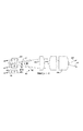
【0030】
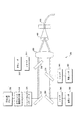
システムプロセスの概要
図2は、患者の身体内にある様々な構成要素が生成する信号が外部計測器で処理される方法と、システム制御用の信号が、患者の身体内にある構成要素に入力される方法を示すシステム50を図示するものである。統合型の画像化および他機能を提供するため、システム50は、患者身体の外部に配置する構成要素と、内部で使用する構成要素(すなわち、点線52内の構成要素)とに分けられる。ブロック54は、走査型光ファイバシステムの遠位端に位置する機能的構成要素を列挙している。ブロック内に示すように、その構成要素として、照明光学系、1つまたは複数の電気機械式走査アクチュエータ、1つまたは複数のスキャナ制御アクチュエータ、スキャナ動作制御用である1つまたは複数のスキャナ動作検出器、ROIを画像化するための光子検出器、および任意に、診断用ならびに治療および監視用の追加光子検出器が挙げられる。システム50では、特定用途に実際に必要とされる機能的構成要素のみが含まれ得ることに留意されたい。また、画像化以外の追加機能として、診断、治療、またはこれらの組合せ機能が可能である。
【0031】
外部では、ブロック56に示すように、照明光学系に照明源および変調器から光が供給される。光ファイバシステムの遠位端に伝送されるRGB、UV、IRおよび/または高強度光を発する外部光源システムの幾つかの好適実施形態に関する詳述を、以下に開示する。ブロック58は、照明源、変調器、フィルタおよび検出器が任意に、患者の身体内の電気機械式走査アクチュエータ(1つまたは複数)およびスキャナ制御アクチュエータに結合されることを示している。スキャナ動作検出器は、走査の制御に使用され、走査制御を実施するためにスキャナアクチュエータ、照明源および変調器にフィードバックされる信号を生成する。
【0032】
ブロック60では、画像化光子検出器により、診断/治療用および監視を目的とする他の光子検出器用に生成される電子信号を用いて、画像信号フィルタリング、バッファリング、走査変換、増幅および他の処理機能が実行される。ブロック56、58および60は、各ブロックで実施される機能を実行容易にする信号を伝送するように、双方向に相互接続されている。同様に、これらのブロックはそれぞれ、画像の取得および処理に使用されるコンピュータワークステーションのユーザインターフェースに供給される信号を処理するため、関連プログラムを実行するため、および他の機能のためにアナログ・デジタル(A/D)変換器およびデジタル・アナログ(D/A)変換器が設けられているブロック62と双方向に結合されて連通している。コンピュータワークステーションからの制御信号は、ブロック62にフィードバックされ、ブロック56、58および60で提供される各機能を制御または作動するために、アナログ信号が適切であれば、アナログ信号に変換される。ブロック62内のA/D変換器およびD/A変換器はまた、データ記憶装置が設けられたブロック64、およびブロック66と双方向に結合されている。ブロック66は、患者の身体内で走査型光ファイバの端部を操作、位置付けおよび安定させるためのユーザインターフェースを表している。このブロック内で行われる安定化機能提供に関するシステムの詳細を以下に述べる。
【0033】
ブロック64において、患者身体内の検出器が生成した画像データを格納するため、また、走査型光ファイバが実行する画像化および他の機能に関連する他のデータを格納するため、データ記憶装置を用いる。ブロック64はまた、ブロック70内のコンピュータワークステーションおよび対話式表示モニタ(1つまたは複数)と双方向に結合されている。ブロック70は、ブロック60からの入力を受け取って、ROIの画像を対話式に表示する。さらに、ブロック72内に示しているように、1つまたは複数のパッシブビデオディスプレイモニタをこのシステム内に含むことができる。ヘッドマウントディスプレイ(HMD)システムなどの他の種類の表示装置を設けて、医療関係者にROIを擬似ステレオ画像として表示することができる。
【0034】
カンチレバー式走査型光ファイバ
図3Aおよび図3Bに、「ジグザグ」または直線走査型光ファイバ80が図示されている。この走査型光ファイバは、生体適合性である、または機械基部86を取巻く生体適合性コーティング84を有する静止機械支持部分82を含む。機械基部86の遠位端から延出しているのは、バイモルフ型圧電ベンダー88である。これは、矢印96で示すように反対方向に曲がることにより、その反対側の両面を横切って印可される電気電圧に反応する。複数の光子検出器92が、中央のカンチレバー式光ファイバまたは導波路94の周囲に配列され、2次的支持ディスク93上に取付けられている。カンチレバー式光ファイバ94は、光ファイバが中に延在しているチューブ方圧電アクチュエータ95により矢印98で示す方向に移動させられる。複数本の導線90aおよび90bが、バイモルフ型圧電バインダ88の側部に延在して、図2のシステム50で示したように、複数の光子検出器からの信号を患者身体の外部に配置されている構成要素に伝送している。図3Aおよび図3Bに示したように、矢印96および98は互いに実質的に直交して、ROIを縦横に走査できるように、カンチレバー式光ファイバ94の走査をジグザグまたは直線状に実行できるようにしている。生体適合性スリーブおよび遠位レンズを含む外枠全体は図示していない。
【0035】
図3Aおよび図3Bに示したジグザグまたは直線状の実施形態は、物理的寸法が実質的により大きく、光子検出器を移動させなくてはならないため、以下に開示する他の実施形態に比較すると好適ではない。例えば、カンチレバー式光ファイバ94の直径は通常およそ0.1mmであり、静止機械支持部82の直径全体は数ミリにもなり得る。
【0036】
圧電アクチュエータ以外の走査アクチュエータを用いて、光ファイバを走査モードで動作させることができる。例えば、図3Cは、鉄棒103を片側に装着して有するカンチレバー式光ファイバ102を含む走査型光ファイバドライバ100を図示している。これにより、電気機械式アクチュエータ110が、コア114の周囲に巻付けられたコイル112内の電流で付勢されると、その鉄棒を引付けて、図に示すように光ファイバを2D式に走査させる。好ましくは、走査型光ファイバを、その共振周波数の調波である1種類または複数種類の周波数で励振して、最適効率を実現する。しかし、光ファイバを共振周波数以外で励振することも考えられる。図示していないが、第2の電気機械式アクチュエータを含めて、電気機械式アクチュエータ110の方向と直交する方向の力を得ることにより、カンチレバー式光ファイバ102を、図3Cに示す方向に直交する方向に走査させることができる。これにより、直角な1対の電気機械式アクチュエータのそれぞれに供給する電流を制御して、カンチレバー式光ファイバ102の走査位置を正確に制御することができる。
【0037】
カンチレバー式光ファイバは、画像化レンズ104を通過して、患者身体内のROIに相当する画像化面106上に焦点を合わせられ、図示のようにPSF108を形成する光を発する。カンチレバー式光ファイバが電気機械式アクチュエータ110により移動させられるにつれて、画像化面106上の異なる位置にPSF108'が形成される。
【0038】
図3Dにおいて、スキャナ122が、カンチレバー式光ファイバ124内に第1のモードの振動共鳴を発生させる電気機械式デバイスまたはピエゾセラミック製チューブアクチュエータを含む、さらに別の実施形態120が図示されている。この場合、 カンチレバー式光ファイバは、その遠位端に位置するコリメートレンズ126と、コリメートレンズを通過した光を照明面132上に再画像化する走査レンズ128とを含む。走査レンズ128により焦点を合わせられた光が、照明面132上でPSF134を形成し、カンチレバー式光ファイバの移動と共に、PSF134'は、照明面上を移動する。カンチレバー式光ファイバ124を、矢印130で示すように単軸に沿って走査するように制限することができるが、直交軸に沿って走査するように(すなわち、図面の平面を出入りする)光ファイバを移動させるアクチュエータを利用することも可能である。しかし、線形単軸型アクチュエータにより励振される高振幅共鳴振動における光ファイバの動作は、機械的な力が非線形に交差結合することにより2次元となり得る。したがって、2D走査に2軸アクチュエータは不要である。
【0039】
走査型薄膜光導波路の実施形態
図3Aおよび図3Bの実施形態に示した断面積より狭い走査型光ファイバを製造し、こうした装置を比較的低価格および少ない容積で製造してより経済的なものにすることで、使い捨て装置としての広範な使用を容易にすると望ましいことを理解されたい。マイクロ電気機械システム(MEMS)技術は、薄膜デバイスを統合型アクチュエータと併用して、こうした目標を実現させるものである。図4A、図4Bおよび図4Cは、薄膜光学システム140の初期原型を図示しており、この手法は有効なものとすでにわかっているものである。図4Dに示す別法140'は、走査用の平行なカンチレバー式薄膜光導波路と検出器とを含む。これらの図に示した薄膜画像化システムを製造するとなると、より小型で、大量生産により適切な型にできそうであるが、この初期原型から少なくとも、この薄膜光学デバイスが有効な走査性能を有し、本発明でも使用可能であることが証明されている。
【0040】
この薄膜光学デバイスにおいて、クラッド142を有する光ファイバ144は、静電アクチュエータ156により作動される。しかしこの場合、静電アクチュエータ156は、光ファイバに走査させるのではなく、隆起した出張り部分148上で支持されている薄膜光導波路150に作用する。すると、薄膜光導波路の遠位部分152は、図4Aおよび図4Bの湾曲した矢印で示す2つの直交方向で走査する。薄膜光導波路の直径はたったおよそ0.005mmである。この走査動作は、1次元(すなわち、単軸沿い)か、図示のように2次元(ラスタパターン沿い)になり得ることに留意されたい。任意に、薄膜光学デバイスをロッド143上に取付けることができる。これを手動または機械的に回転または振動させて、配向を変える、または単軸走査を変位させる。また、シリコン基材146(または他の基材材料)に好ましくは取付けられたレンズ154を設ける。別法として、静電アクチュエータではなく、外部アクチュエータ(図示せず)を用いることができる。この場合、光ファイバ144およびレンズ154をシリコン基材146で支持し、これを外部アクチュエータにより振動させて、カンチレバー式薄膜光導波路を共鳴走査させる(resonantly scan)。光ファイバ144を、薄膜光導波路150との位置合わせを確実にするために、好ましくは、中心のV字型ノッチ160内でシリコン製基材146に固着する。光ファイバの直径はおよそ0.1mmであるため、光ファイバの端部と薄膜光導波路との間の正確な位置合わせを慎重に行わなくてはならない。
【0041】
図4Aおよび図4Bは、光ファイバ144と薄膜光導波路150との間を突合わせ結合した実施形態を示すものである。光ファイバと薄膜光導波路との間を適切に位置合わせするため、V字型ノッチ160により、光ファイバを薄膜光導波路に対して正確に配置する。図4A、図4Bおよび図4Cに示す実施形態を見ると、ROIから反射して戻った光は、レンズ154を通過して、RGB検出器162r、162gおよび162bにそれぞれ受け取られる。これらの検出器は、上述したように、対応する色の光に応答して、近位の外部構成要素まで伝送される信号を生成する。図4Dでは、別個の画像化および診断/治療用薄膜光導波路が、距離をあけて配置されており、並行して走査する。この実施形態は、診断用「DIAG」検出器162dを使用している。
【0042】
先細り状および他の走査型光ファイバ
比較的小さな照明PSFを形成するために、他の技術を用いることもできる。例えば、図5Aおよび図5Bに示すように、従来の光ファイバ164は、テーパ部分166を具備する微細加工された端部168を含む。この微細加工端部は、エッチング(最も好ましい)や微細機械加工により、または、加熱した光ファイバを引張った後、伸びたファイバを所望まで細くなった直径部分で切断すること(好ましさの程度が最も低い)により、形成する。遠位先端部においてクラッド層を最小厚さまで化学エッチングすると、光伝送の損失のない状態でこの先細り加工を行うことができる。光ファイバを引張って寸法を縮小すると、その処理時にたいてい光伝送の損失があるため、任意に、反射性コーティング167を先細り形状の導波路側部に適用することができる。しかし、これらの処理を組み合わせて、微細加工を施し、走査周波数、FOVおよび解像度を改良した光ファイバスキャナを形成することができる。微細加工端部168を有する走査型光ファイバを用いることの1つの利点は、図5Bに示す光ファイバの共振周波数が、微細加工を施していない鈍い先端部を有する光ファイバの共振周波数より実質的に高いことである。しかし、主な利点は、先細り状ではないファイバに比較すると、より高い共振周波数において、先端部をより大きな振幅で偏向させられることである。上述したように、微細加工端部168の遠位動作は、線形パターン169aと2次元パターン169bとなり得る。さらに、微細加工されていない光ファイバと比較すると、先端部の偏向が大きければ、横方向の先端部変位は小さくなる。微細加工した先細り端部の形成に好ましくは用いるエッチング処理は、当業者に周知の技法を用いて行う。
【0043】
図5Cに示すように、様々な形態の光ファイバに対する相対的PSFおよびFOVは、ROI170に向けて光を出す光ファイバ遠位端の置かれる部位の性質に応じて変化する。この図では、共鳴振動の第1、第2および第3のモードにおける具体的な光ファイバの変位を、点線で示している。鈍い端部を有する光ファイバ172は、第1の共鳴モードにおいて単軸を中心にして振動するように駆動されて光174を出す。この光は、レンズ184により焦点を合わせられてPSF176を形成する。光ファイバ遠位端における部位の寸法が他の場合より大きいため、このPSFは最も大きいものとなる。最小のPSF182は、より高い共鳴モードで単軸に沿って駆動される先細り形状の光ファイバ178 (上述したように、エッチング、微細機械加工、または引張ることにより形成)から出た光180が形成するものである。この先細り状光ファイバが共鳴して振動する物理的走査距離は比較的小さいため、小さな直径の筐体内に収められることに留意されたい。遠位端をボールレンズ186に結合し、第2のモード(節がボールレンズ内)で駆動される光ファイバ184からの光188は、レンズ185を通過して、3つの構成の中では最も大きなFOVをカバーする中間サイズのPSF190を形成する光となる。図5Cに示す第2および第3のモードにおける実施形態が、単一アクチュエータのみを必要とし、断面寸法が比較的小さく、解像度が比較的高く、ROIに対する多様な走査ができるため、一般に好ましい。
【0044】
上述した線形モードや直線状またはジグザグモードと異なる他の走査モードも実現可能である。図5Dは、2軸ピエゾセラミックチューブアクチュエータ206により形成可能な、光ファイバ走査システム200の可変半径または螺旋状走査モードを示すものである。この実施形態では、ROI(この図では示さず)から受け取る光を示す信号を生成するために、複数の光検出器204が、単一のピエゾセラミックチューブアクチュエータ206の周囲に単純に配列されている。別法として、同心状で離間して配置された光ファイバ202の同様の配列が、その遠位端でROIからの光を受け取って、その近位端の光検出器(図示せず)(例えば、患者の身体外)まで伝送することができる。ピエゾセラミックチューブアクチュエータ206は、遠位端210で先細り状になっているクラッド光ファイバ208を同心状で包囲している。このチューブアクチュエータが、光ファイバ208の固有共振周波数の調波に対応する駆動力を生成することにより、光ファイバの遠位端は、作動制御半径を有する軌道212を描く。走査型光ファイバの遠位端には光点源があり、その焦点を、画像化レンズ(図示せず)を追加することにより、照明面(図示せず)に合わせられる。上述した他の実施形態に対するこの実施形態の主な利点は、この実施形態では、単一アクチュエータおよび先細り状導波路を用いて、高解像度、有向照明、および比較的小さな直径枠内における画像化を得ていることである。
【0045】
一連の可変半径円が、円形走査モードにおいて光ファイバにより描かれ、螺旋走査モードにおける光ファイバは、半径が交互に増減する螺旋走査を行う。この円形または螺旋走査モードにおいて、光ファイバ208の遠位端は、その領域を画像化するためにROIを走査し、そのROIに対する治療および/または診断機能も行う。カンチレバー式光ファイバの旋回動作は、ピエゾセラミックチューブアクチュエータ206の各四分区間に印可される電圧を増減することにより、直径のより大きな、またはより小さな範囲に制御自在に駆動される。「プロペラ」走査モード216を図5Eに示す。この走査モードにおける走査型光ファイバは、円の様々な直径に沿って前後に移動しながらROIを走査する。2軸ピエゾセラミックチューブアクチュエータにより、または、光ファイバの長手方向軸を中心に単軸アクチュエータを単に回転させることにより、この線形走査を回転させることができる。
【0046】
画像化、診断および治療用に最大FOV全体のピクセル数を最大にするには、レンズシステムにより、照明の回折限界スポットを形成しなければならない。理想的な走査型光ファイバを想定すると、出力された照明の空間解像度は、投射される光点源サイズとレンズシステムの回折限界または収差限界の(aberration-limited)性能とにより制約を受ける。収差が制限されている光学システムの場合、図5Fで2次的画像化レンズまたは小型レンズ228をファイバ先端部に配置する主な目的は、光収差を低減して、照明スポットサイズを縮小することである。回折限界光学システムでは、より大きなレンズまたは走査した光学照明ビームを用いて、スポットサイズをより小さくすることができる。したがって、図5Hに示すように、固定FOV内のピクセルを増加させるには、高解像度光学設計において特大コリメートレンズまたはボールレンズ245を用いる。回折限界のコリメートレンズおよび走査レンズを想定すると、約1.0mmの直径枠内である光ファイバ走査システムで最大のピクセル数または表示解像度が理論的に可能である。図5Fおよび図5Hに示す横方向振動共鳴モードが、移動する導波路を大きく横方向に変位させることなく、遠位先端部における高角度偏向の要件を満たしていることに留意されたい。旋回またはプロペラ運動で走査することにより、この実施形態では、超薄型単一ファイバシステムにおいて高解像度も広角FOVも得られる。
【0047】
したがって、図5Fは、ビーム走査型実施形態220を詳細に示すものである。これがおそらく、上述した実施形態の中で最も好適である。上述した図5Cから、光ファイバの遠位端にボールレンズを使用すると、他の形態の走査型光ファイバよりも広角なFOVにわたり常に小さなPSFを形成できるため、図5Gで示すように、比較的小さなスポットサイズ240となることを思い出されたい。ビーム走査型実施形態220は、円柱状の支持筐体222を含む。この筐体内には、圧電またはピエゾセラミックタイプの円柱状アクチュエータ244が配置されている。このアクチュエータは、光ファイバが曲がって、このデバイスの公称長手方向軸の両側に節を形成するように、光ファイバ226を駆動して共鳴2D走査モードで振動させる(図5Hに示す例に関しては以下でさらに説明する)。ボールレンズ228が光ファイバ226の遠位端に固着されている。光ファイバ内を伝送された光は、ボールレンズおよびレンズ238により焦点を合わせられてビーム230を形成する。ビーム230は、好ましくは、光ファイバおよび円柱状筐体222の長手方向軸に対して少なくとも40°以上の角度をなしている。走査時、図示のように、光ファイバのカンチレバー部分の中心がこの軸を中心に前後に移動するが、ボールレンズ228の中心は、その慣性質量と振動節が第2の共鳴節にて先端部付近にあることとによりほぼ静止状態を保つ(図5C参照)。アクチュエータ224を超えて遠位に延在する光ファイバ226の長さとボールレンズ228の質量とを、確実にこの動作形態で走査が行われるように選択する。光検出器232は、円柱状アクチュエータ224の周囲に配置する。このアクチュエータを、検出器への後方散乱光の高効率誘導を補助するように高反射性材料(例えば、アルミニウム)237でコーティングすることができる。
【0048】
理論的に、後方散乱した走査光を収集し、モノクロまたは白黒画像を形成するには、単一光検出器のみが必要である。フルカラー画像を生成する単純な方法は、青、緑または赤の光伝送を透過するように選択された異なるフィルタでそれぞれカバーされている3つの光検出器(上述のように)を使用することである。可視光および近IR光の検出には、その高感度、低コスト、小型寸法、高速度および丈夫さから、シリコンを主成分とする半導体フォトダイオード(Si-PINタイプなど)が好適である。InGaAs材料製フォトダイオードなどの通信産業で普通に使用されているフォトダイオードが、IR光を検出する本発明の実施形態に好適である。統合型光走査技術の解像度は、光検出器の寸法および数に左右されるものではないため、信号のレベル間を増幅して識別することを目的に、光ファイバアセンブリの遠位端で利用可能な空間すべてを光検出器でカバーすることができる。以下の説明でより明白になるが、ROIの形状上の特徴(陰など)の画質を高め、スペクトル反射からのグレアを消滅することができるように、光検出器を、好ましくは、光軸を中心にステレオペアで設ける。IR放射線を可視光と併用する場合、異なる感光材料による複数の光検出器をフィルタなしで使用することができる(図示せず)。フィルタリングされていない検出器のスペクトル応答を分離する別法では、パルス出力を有する適当な照明源と検出器信号を同期させなくてはならない。例えば、RGBレーザまたは他の光源がそれぞれ、迅速な時系列で、光検出器から受け取る信号処理と同期してパルス化される場合、同じ可視光検出器をフィルタなしで使用することができる。
【0049】
リード234が、光検出器のそれぞれから、患者身体の外部にある光ファイバの近位端まで延在して、上述したように、光検出器からの電気信号を外部計測器まで伝送する。アクチュエータ224は、リード236から供給される電気信号で駆動される。
【0050】
アクチュエータ224などのアクチュエータの駆動により振動される光ファイバ244の動作をわかり易くする詳述を、比較的小さなユニットでより高い解像度を提供する、特大コリメートレンズを用いる図5Hに示す。光ファイバ244はクラッド242により包囲されており、その遠位端は、光ファイバ244内を移動してきた光を平行にするボールレンズ245に結合されている。上述したように、光ファイバ244のカンチレバー部分の中心は、上方から下方に偏向する間、ボールレンズ245は、その質量が比較的より大きいため実質的に静止状態を続ける。光ファイバ244内を移動してきた光は、光ファイバが図示のように走査範囲の上方と下方との間を移動する際に、ボールレンズ245の中心246を通過する。ボールレンズ245を通過した光は、直径をおよそ0.5mmにコリメートされて走査レンズ248から出る。光ファイバ244がその最大振動幅時になすボールレンズ245の中心246からの内包角は、およそ60°である。したがって、走査レンズ248から出た光がROIを走査して形成するPSFまたはスポットサイズは比較的小さい。この特大ボールレンズ型実施形態は、「Single Fiber Flexible Endoscope: General Design for Small Size, High Resolution, and Wide Field of View」、Eric J. Seibel Quinn、Y. J. Smithwick、Chris M. BrownおよびPer G. Reinhall著、Biomonitoring and Endoscopy Technologies, Proceedings of SPIE, 第4158号(2001年1月)に記載されている。その開示内容は参照により本明細書内に組み込まれている。光ファイバの遠位端にレンズを設ける実施形態は、屈折率分布型レンズ、回折または光学構成要素、または回折および屈折レンズの組合せを使用できる。
【0051】
画像化およびスペクトル解析または偏光解析用光ファイバシステム
図6Aは、本発明による、ROIの擬似ステレオ画像提供と、分光光度計で解析可能なスペクトル画像取得との双方に使用するシステム266を示すものである。このシステムにおいて、光ファイバアセンブリ250は、遠位端が先細り形状となっており、圧電アクチュエータ254で包囲された光ファイバ256を含む。アクチュエータ254が、光ファイバ256を振動させ、レンズ258aおよび258bを通過する光を発しながらROIを走査させる。ROIからの反射光や、ROIから受け取る他の光(燐光または蛍光発光など)を、光ファイバ256の周囲で周方向に1列に配置された12本の光ファイバ252が収集する。この図に例示したように、集合として参照番号を260とする光ファイバ1、2および3はそれぞれ、周方向列の左側に対応する外部RGB画像検出器に結合されている。同様に、集合として参照番号を262とする光ファイバ7、8および9はそれぞれ、周方向列の右側に対応する外部RGB画像検出器に結合されている。もう1つのセットである、光ファイバ4、5、6、10、11および12に対応する光ファイバ264は、分光光度計270に結合されている。分光光度計は、紫外線、可視光および/またはIR光を用いた、スペクトルの解析およびスペクトル画像の取得を目的に使用するものである。主方向列の左側および右側に対応するRGB検出器が、列の離間した2つの部分(すなわち左側および右側)におけるROIからの光を受け取るため、この検出器から、HMDディスプレイ(図示せず)を用いれば容易に見ることのできる擬似ステレオフルカラー画像が得られる。
【0052】
本発明によるもう1つのシステム271が図6Bに図示されている。システム271では、光ファイバ束250が光ファイバ256の周囲で同心状に配置され、プリズム/格子と、ROIからの光のスペクトルを測定するためのスペクトル検出器列とを使用する分光光度計272に結合されている。分光光度計272からの出力信号は、コンピュータワークステーションおよびスペクトル分析装置274に入力され、そこで、RGBビデオディスプレイ276上にフルカラー画像が形成される。また、コンピュータワークステーションおよびスペクトル分析装置274は、ROIのスペクトル分析および診断に使用可能なスペクトルディスプレイ278に接続されている。標準内視鏡画像およびスペクトルマッピングと、他のあらゆる追加診断/スクリーニング情報との双方の統合表示を、テキスト、擬似色のオーバーレイ、音響強化、立体画法による画像などの複数の形式279で一緒に示すことができる。システム266と同様に、患者身体内に配置される光ファイバシステム部分は、点線の長方形で囲んで示している。
【0053】
光ファイバの走査を制御するため、追加光検出器およびエミッタを走査型光ファイバに隣接して(並列または隣接)使用することにより、光ファイバ遠位先端部の時間経過に伴う動作および位置(または周波数および速度)を検出することができる。図6Aに示すように、光ファイバがより急峻に折れ曲がって光の漏れ量が増加した場合、それを受動光子センサ255で検出することができる。
【0054】
図6Bにおいて、IRエミッタ281およびIR検出器283が、光ファイバスキャナの両側に配置されており、光ファイバ256の振動する先細り状遠位端または先端部の位置が変化することによる光学的光透過量の変化を利用して、その先端部の位置を制御する。図6Cでは、エミッタ281および検出器283は、互いに隣接して(並んで)配置されており、これを用いて反射光の変化を検出する。これらの方法は、光ファイバ感知業界では普通に使用されており(ただし、走査制御用ではない)、別個の非画像化波長のエミッタおよび検出器は、走査型プローブマイクロスコープの制御に特に有用である。これらのセンサからの信号は、圧電式、磁気式または静電式のいずれでもよく、スキャナの歪みを低下させつつ走査率を高めるフィードバックコントローラで使用される。
【0055】
治療用に有向照明を発する走査型光ファイバシステムの空間解像度は、照明画像面上に投射され得る光の識別可能なスポット数により左右される。解像度は、最小スポットサイズに左右され、FOVは最大走査角度(識別可能なスポットの合計数)に左右される。画像を取得した場合、空間解像度はまた、光子検出器の帯域幅(信号対雑音比が十分であると仮定して)およびディスプレイシステムに利用可能なピクセル合計数に左右される。走査システム構成要素の帯域幅制限内で操作することにより、解像度およびFOVを動的に変化させて、ROIの表示倍率および動的倍率変更などの機能を実行できるようにする。多くの用途において、ROIも単一光ファイバシステムも静止状態にあるため(走査している光ファイバの遠位端以外)、走査によるぼけの発生率は、ディスプレイ装置の再生率を大幅に下回るまで低下する。標準ビデオ撮影速度よりゆっくり走査することにより、この光学システムは、より高い電力を光学治療に提供し、より長い時間にわたり、信号の弱い蛍光診断から信号を統合することができる。したがって、走査型光学システムのダイナミックレンジは、システムの構成要素および用途要件にしたがって最適化することができる。
【0056】
フレーム毎に1ピクセルまたは数ピクセルのみの照明を発することができる。例えば、本発明を用いると、ROI内の1地点について実時間による光学的生検を実行でき、極めて明るい励起光を用いることができ、正常画像に対する分光学的取得およびスペクトルマッピング用の時間が得られる。
【0057】
図6Cは、クラッド286で囲まれた比較的細い中心光ファイバ284を含む同心状光ファイバアセンブリ280の一部を示すものである。細い光ファイバを、それより直径の太い光ファイバが取り囲んでいる。ROIの照明は、直径の小さい光ファイバ284を介して得られ、ここから発せられる光はレンズ288a、288bおよび288cを通過してROIを照明する。反射および反射以外でROIから受け取られる光の焦点は、これらのレンズにより光ファイバアセンブリ289内に戻って合わせられ、このアセンブリにより、患者身体外に配置されている計測器まで伝送される。このいわゆる同心共焦点型画像化では、単一光ファイバが、ROIの照明もROIからの光の外部計測器への伝送もできることに留意されたい。この同心状光ファイバ構成は、互いに融合されているか、あるいはまた、ガラス繊維を半径方向にドーピングすることにより屈折率の異なる同心状領域を製造することができるかのいずれかである単一機械ユニットである。管状圧電アクチュエータ282が、この同心状光ファイバを一緒に移動させて、上述したモードの1つでROIを走査させる。周囲の光ファイバ内で収集される光を反射された共焦点から半径方向に離れる距離における検出器または光ファイバからの信号と併用して、診断、画像化および治療を目的に画像解析を改良し、光浸透距離を深くすることができる。極端に振幅利得または信号弁別の高い検出構造では、後方散乱光を導波路の同じ部分(例えば、光ファイバのコア部分)で収集することができる。このような応用例では、光学的可干渉性能を用いて、低い信号レベルを増幅し、光干渉式反射率測定(OCR)や光干渉式断層撮影(OCT)、またはレーザ誘起フィードバックを基に診断地図を形成することができる。
【0058】
図6Dおよび図6Eは、RGB、UVおよびIRスペクトル成分用検出器を含む実施形態を図示するものである。光ファイバアセンブリ295は、支持体293上に取付けられた内部アクチュエータ291を含む。光ファイバ300は、開口298を有する筐体内に収容され、アクチュエータ291の遠位方向に延在しており、上述したモードの1つで、好ましくは管状圧電方である内部アクチュエータにより移動させられる。図6Eに示すように、RGB検出器292および294は、光ファイバ300の上方および下方に配置され、RGB検出器306および308は、光ファイバの左および右に配置されている。さらに、これらの図で示すように、RGB検出器290および296は、アセンブリの頂部および底部にてその外面に配置されている。同様に、図6Eに示すように、RGB検出器302および304は、検出器の左側および右側に取付けられている。UV検出器310および312は、RGB検出器の間で一方の対角線上に取付けられ、IR検出器314および316は、RGB検出器の間でもう一方の対角線上に取付けられている。したがって、擬似ステレオ画像を、このアセンブリに含まれる様々な検出器で受け取るRGB、UVまたはIRスペクトル成分について形成することができる。
【0059】
図6Fおよび図6Gは、平行および垂直偏光検出器を含む光ファイバアセンブリ295'を示すものである。光ファイバ300が、参照番号328で示す平行な方向に偏向される光を伝送する。図6Gに示すように、光ファイバ300の両側には平行偏光検出器334および336が配置されており、光ファイバ300の上方および下方に垂直偏光検出器324および326が配置されている。さらに、垂直偏光検出器320および322が、垂直偏光検出器324および326の上方および下方に配置され、平行偏光検出器329および330が平行偏光検出器334および336の左および右に配置されている。したがって、光ファイバアセンブリ295'は、患者身体の外部に配置されている計測器で解析するため、ROIから反射された、または反射以外にROIから受け取る両方の向きの偏光を検出することができる。また、特定種類の偏光に対応する画像を形成するために、様々な偏光検出器が生成する信号を用いることができる。
【0060】
図7Aには、異なるスペクトル成分の光を発する、光ファイバ360内に結合された光源システム340が概略的に示されている。この実施形態では、赤光源342、緑光源344、青光源346およびUV光源348がそれぞれ選択的に光ファイバ360内に結合される。光源それぞれに増幅器350が設けられて、光源からの光の強度を選択的に制御できるようにしている。対応する緑、青およびUV光源のそれぞれが発する光の色に特異のコーティングを含む3つのダイクロイックミラー352、354および356が、緑、青およびUV光をそれぞれ光ファイバ360の近位端内に反射するように光路内に配置されている。各ダイクロイックミラーの反射帯域外である光はそのダイクロイックミラーを通過し、レンズ358により光ファイバ360の近位端内で焦点を合わせられる。
【0061】
別法による光源システム362を図7Bに示す。この実施形態では、赤光源342、緑光源344、青光源346はそれぞれ、任意の増幅器350を介し、レンズ364を介して、一連または1配列の光カプラ366に結合されている。レンズ364は、異なる色の光源それぞれから発せられる光の焦点を光ファイバ365内で合わせる。光ファイバ365がその光を光カプラ366に伝送する。さらに、IR源368は、光を任意の減衰器350およびレンズ364を介して光ファイバ365内に伝送する。光ファイバ365はそのIR光を列の最後の光カプラに伝送する。光検出器370を、異なる光源それぞれについて光の強度レベルまたは出力レベルを監視するために設けて、様々な光源の強度を制御できるようにする。最後の光カプラからは、光ファイバ367が光を光検出器370に伝送入力し、最後の光カプラからの出力は、光ファイバ360の近位端に入力されて、患者の身体に入力される。光源寸法による影響を最も低く抑えるため、図7Cで選択される光ファイバは、青色光の波長以上の波長に対する単一モードとする。
【0062】
図7Cに、多スペクトル成分レーザ光源システム380が図示されている。このシステムでは、可変波長IRレーザ382が、任意の周波数倍増器384からシャッタおよびパワーメータ386内に通過するIR光を生成する。このシャッタおよびパワーメータを制御して、IR光の強度を変調し、また患者身体内に延びている光ファイバ402の近位端に適用するかどうかを制御することができる。別法として、可変波長IRレーザ382の周波数を倍増して、より短い波長の光を発することができる。さらに、緑色レーザ388は、複数のシャッタ390の1つを通過する緑色コヒーレント光を生成し、青色レーザ392は、やはりシャッタ390に制御される青色コヒーレント光を生成する。同様に、赤色レーザ396は、赤色コヒーレント光を生成する。様々なレーザ源からの光のレンズ398を介する伝送には、複数のダイクロイックリフレクタ394を使用し、その焦点を、先細り状の中空ガラスチューブ400内で合わせる。先細り状の中空ガラスチューブのテーパ角度は、その内面での内部反射により、各レーザ源からの光が光ファイバ402の近位端内に「注ぎ込まれる」ものとなっている。波長を組み合わせて注ぎ込まれた光は、中実コアまたは中空コア光ファイバに伝送して、その光ファイバの遠位端にてROI内の組織に出力することができる。各レーザ源からの光の強度は治療用および診断用に比較的高くなっているが、先細り状中空ガラスチューブ400は、レーザ源からの高出力信号を容易に組み合わせることができる。中空ガラス注入口に関するさらなる詳述は、論文「Ultraviolet, Visible, and Infrared Laser Delivery Using Laser-To-Fiber Coupling Via a Grazing-Incidence-Based Hollow Taper」、I. IlevおよびR. W. Waynant著、オランダ、アムステルダム、2000年7月4日付の会報EOS/SPIE/ELA European Biomedical Optics Week-EbiOS 2000内に提供されている。この論文は、2001年にも「Proceedings of the SPIE, Biomonitoring and Endoscopy Technologies」の第4158号として発行されている。また、「Uncoated Hollow Taper as a Simple Optical Funnel for Laser Deliver」、I. IlevおよびR. W. Waynant著、Review of Scientific Instruments、第70巻、No. 10、3840-3843頁(1999年)も参照されたい。
【0063】
機能ブロック図
図8は、本発明で実施できる様々な機能を示すものである。診断、治療および監視などの機能を、点線で囲まれたブロックで示し、システム410の画像化機能には実線を用いている。図示のように、画像化レーザ412は、患者の身体内に向けられ、走査型光ファイバの画像化光学系を介する光を生成する。さらに、ブロック416内の診断、治療および監視用レーザは、遠隔光学スイッチにより制御され、ブロック418内の減衰器は、光学結合機構420を介して、患者身体内に配置されている追加光学構成要素422に伝送されるコヒーレント光を生成する。RGB光子検出器430は、ROIから受け取る光に応答して電気信号を生成する。この信号は、導体を介して、患者身体外に配置された計測器に伝送される。別法として、RGB光を、光ファイバを介して外部光子検出器426または、例えばフォトダイオードおよび関連電気回路を含む他の光検出器424に伝送することができる。ボックス432内に示すように、このシステムは、1つまたは複数の分光光度計またはスペクトル分析器で使用するために、光収集用光ファイバに関連する追加高出力または低出力UVおよび/または可視および/またはIR検出器を含むことができる。例えば、ブロック434内に示す分光光度計スペクトル分析器は、光収集用光ファイバ内で伝送された光を、および/またはブロック436内に示す導体で伝送された信号として受け取ることができる。このシステムは、さらなる選択肢として、患者身体内に配置される追加光子検出器を含むことができる。信号は、ブロック432および434とブロック440内のコンピュータワークステーションおよびデータ取得構成要素との間で双方向に交換される。このコンピュータワークステーションは、非線形走査パターンを提供するアルゴリズムと制御アルゴリズムとを実行することができ、また、強度データの取得、画像マッピング、およびデータの記憶を実行するようにプログラミングできるものである。さらに、リアルタイムフィルタリング(例えば、動作およびスキャナアーティファクトの補正)、比率およびバックグランド減算のリアルタイム決定、デコンボリューション、擬似ステレオ強調、および様々な検出器が生成する信号の処理が、このコンピュータワークステーションにより実行される。このコンピュータワークステーションが提供する信号は、画像表示装置およびデータ記憶装置に出力される。画像表示装置はブロック442に示すように、陰極線管、液晶ディスプレイおよびHMD装置または他の種類の立体画法によるディスプレイを含むことができる。この統合型単一ファイバシステムは、3D画像を伝送でき、手動操作が不要であることから、将来、侵襲度を最小限にした遠隔手術および自動機械式処置にさらに容易に適用できるようになろう。市販のMIMP用ディスプレイは直線型ビデオフォーマットが必要であることから、非直線型である光学操作パターンはいずれも、非直線型走査の多くの利点(簡素型単一アクチュエータ、円柱状スキャナ寸法およびより低い走査速度など)を利用するために、データバッファ(メモリ)内に格納して、表示モニタ用に標準ラスタ走査形式に変換しなければならない。信号調整および再マッピングにおけるこの追加ステップは、プログラム可能な記憶装置では技術的に取るに足りないものである。
【0064】
さらに、スペクトルおよび多変量解析を実行し、関心領域の境界を位置決めおよび算出するための画像解析ソフトウェアは、コンピュータワークステーションや他の計算機デバイスを用いて実行される。ROIについて、算出により、その分布、境界、容積、色および光学密度を特定することができる上、ROIから収集されたデータに基づいて、組織の疾患状態、医療的段階付けを決定し、治療用放射線量を算出および監視することができる。これらの機能のすべてをブロック444内に示しており、ブロック440の通常の画像化コンピュータワークステーションを使用することができる。ブロック444はブロック446につながっている。ブロック446では、追加対話式ディスプレイおよび画像オーバーレイフォーマットが提供される。ブロック444に関連するブロック448では、電気機械式スキャナを作動させ、ブロック450内のサーボセンサから信号を受け取るためのスキャナ電力制御エレクトロニクスが提供される。サーボセンサは、通常の画像取得およびスクリーニング、監視および診断に関わる改善と治療用ピクセルの正確な出力との双方に使用される。
【0065】
以上、光ファイバ走査アクチュエータの様々な実施形態について記載してきた。ブロック454は、光ファイバを患者身体内に挿入し、ROIに隣接した所望の位置に配置できるように、走査型光ファイバの遠位先端部を手動制御するための準備が整えられることを示している。手動制御は、走査型光ファイバを所望の位置に導入することを容易にできるように、ブロック456で示すように、位置転換装置およびサーボセンサを含むことができる。配置後、ブロック452に示すように、患者の生体運動(呼吸および心臓血管による動作)および物理的動作に関する画像を安定化させるために、自動振動補正を行う。さらに、身体の空隙内または患者身体内通路で所望する位置に光ファイバを安定化させるために、以下に開示する少なくとも一実施形態において、他のメカニズムが設けられる。
【0066】
本発明で実施可能な様々な機能の詳細を以下に記す。
【0067】
統合型画像化、スクリーニングおよび診断
・UV、可視およびIR波長を用いた光学的な組織の画像化
・UV、可視およびIR波長を用いた蛍光画像化
・IR波長を用いた熱画像化
・IR波長を用いた深層組織画像化
・同心共焦点および真共焦点画像化
・IR波長を用いた血液を介する画像化
・偏光コントラストによる画像化
・レーザフィードバックによる顕微鏡検査法
・光干渉式断層撮影(OCT)および光干渉式反射率測定(OCR)
・光学的誘発による振動音響分析
・高解像度および高倍率の組織接触式画像化
・レーザ誘起蛍光(LIF)およびレシオ蛍光(ratio fluorescence)による画像化および検出
・多光子励起蛍光による画像化
・蛍光寿命による画像化および解析
・ステレオレンジファインダオプションを用いた画像構造の真寸法調節
・レーザ誘起蛍光分光(LIFS)
・ラマン分光分析
・弾性散乱分光(ESS)解析
・吸収分光分析
・化学発光および細胞生存能力の検出およびマッピング
・光学センサデータ(酸素濃度、pH、イオン濃度など)の空間マッピング
・温度測定およびフィードバック制御
・その他、監視およびフィードバックを目的とした、色、レーザ出力送出、組織性能、フォトブリーチング、化合物のフォトクリエイションの測定
【0068】
治療、手術および監視
・光力学治療(PDT)
・組織および/または腫瘍に対する加熱(例えば、温熱療法)
・光学照明によるレーザ手術(UV、加熱および/または切除)
・化学反応の光活性化、光重合、および生体材料の移植
・スキャナの高温先端部によるレーザ焼灼 (光学的または電子的に加熱)
・光学的パルス照射の吸収で生成された衝撃波を用いる組織の機械的破壊
【0069】
対話式ディスプレイおよび高度ユーザインターフェース設計
・表示モニタ上の擬似ステレオ、擬似カラーの重ね合わせを用いた立体画法によるマッピング、および真3D表示フォーマット(注:各ディスプレイの戦略および性能は、具体的用途により変わるものである。)
・対話式タッチ/ポインティングスクリーン(point screen)
【0070】
図9Aおよび図9Bは、使用する計測器に応じて変化する、本発明で実行可能な別の機能を示すものである。図9Aは、画像化、サンプリング、診断および治療の実施用に用いられる単一走査型導波路を示し、図9Bには、3D画像化、腫瘍生検の実施、および内視鏡手術の監視用に用いられる単一走査型導波路を示している。どちらの図にも同一構成要素が多く使用されているため、システムの一部として使用する構成要素をわずかに変更すれば、異なる機能が得られることがわかる。図9Aに示すシステム460では、対話式コンピュータワークステーション462があるため、専門医は走査型光ファイバを制御し、画像化、診断(例えば、光学的生検)および治療実施に用いるソフトウェアアルゴリズムを実施することができる。高解像度であるカラーモニタ464が、光ファイバシステム488から分配コンソール472まで伝送された、走査型光ファイバ484からの信号を受け取る。患者身体の内部に含まれていない場合には、任意のRGB検出器を走査型光ファイバ484に隣接して設けることができる。ROI486を光ファイバで走査して、ユーザに表示する高解像度カラー画像を生成する。パッシブディスプレイの実施形態では、2つの陰極線管モニタ(CRT)が、同じ対象物(例えば、組織)に対して複数の画像を形成するために2種類のコントラストモードを用いて画像を表示する。例えば、同じ共鳴駆動による走査型光ファイバは、一方のCRTにはフルカラー光学画像を、またもう一方のCRTモニタにはグレースケール蛍光画像を生成することができる。励起および信号の光学特性が一致しないと、2つまたはそれ以上の画像が同じに形成される場合がある。そうでなければ、2つの画像が、フレームシーケンス方法により取り込まれるか、高速共鳴スキャナの交互のラインスイープで取り込まれる。画像コントラストのモード(フルカラー光学系と蛍光)を切り替えるには、光源を遮断するか、直接光源の電源を切る/入れる。光子検出器からの信号は別々の画像として記録および表示される。照明パワーおよびスペクトル範囲の双方の調整時に同期すると、光子検出器からの信号が記録され、別個の画像として表示される。同じROIに対する第2の蛍光画像を有するこの実施例では、専門医は、標準の白光画像では見えたり見えなかったりする小さなまたは前癌性病変を見つけ、明確に識別することができる。
【0071】
2つのディスプレイのうち一方を、専門医がレーザ手術を行うROIを選択できる(輪郭を描く)タッチスクリーンモニタにすることが考えられる。この画像が可動型の場合があるため、タッチスクリーンモニタは、画像を取り込まれて一時的に静止させられるものでなければならない。しかし、このROIの輪郭を描いたら、画像細分化および対象物認識用アルゴリズムを実施して、実時間画像の取得および表示中、そのROIを強調表示させておくことができる。タッチスクリーンモニタでは、パワーレベルおよびレーザ放射曝露時間などのレーザ治療用パラメータを設定するために、専門医はサイドバーメニュを利用することができる。第2のディスプレイは対話式ではなくてもよいが、好ましくは、実時間光学画像をフルカラーまたはグレースケールで表示する高解像度モニタとする。IR光子検出器が内視鏡と一体化している場合、擬似カラーを用いた高解像度表示が得られるため、専門医は、レーザ手術における組織の加熱および/または組織への照射などのレーザ治療の進行具合を監視することができる。
【0072】
ブロック466に示すように、案内ワイヤやカニューレ(図示せず)、および先端部の操縦および安定化を可能にする手動コントローラを用いて、走査型光ファイバを、患者の身体内でROI486に対向する所望の位置に配置する。ROI486内では、光学的生検「スポット」485が、疾患を診断するための一点スペクトル測定の空間的および時間的分布を示している。これらのスポットは、体外生検解析用に組織サンプルを侵襲的に採取する現在の診療とほぼ同様に配分されている。各スポットを、光学スキャナのフレームサイクル中に、t1とt2とを例えば約1/30秒毎に分けて、分光学的に解析することができる。走査型光ファイバから得る画像の他に、ブロック468に示すIR熱による光検出器(および光学的温度モニタ)を含めて、IR信号をROIから受け取ることができる。
【0073】
走査型光ファイバや光導波路の動作の制御を容易にするため、ブロック470に示すように、マイクロセンサおよび制御電子回路用電力を提供する。ブロック470内において、光ファイバを走査させるアクチュエータが、電気的ハードウェアとソフトウェアとの双方で制御されると、制御電子回路から得た信号で、光ファイバの振幅および変位を制御することができる。ROI486から受け取るスペクトル組成および光学的生検位置485の分布を、専門医がガンなどの疾患に対してスペクトル測光解析に基づいてそのROIの状態を評価するに当たり、スクリーニングおよび診断用に用いることができるため、分光光度計および/またはスペクトル分析装置474を診断用に含める。ROIを画像化できるようにROIを照明するため、赤色、緑色および青色光源476、478および480を組み合わせてできあがる光を、光ファイバシステムを介して走査型光ファイバ484に伝送する。スペクトル分析に使用する光源は、RGB光源(例えば、レーザ)の1つ、2次的レーザまたは白色光源からの高出力パルスでよい。信号の強度、時間および照度の制約があるため、フラッシュ照明を用いて、繰返し一点分光法(repeated single point stereoscopic method)をまずとる。さらに、同じまたは別の高出力レーザ源482を用いて、PDT、腫瘍のレーザ切除、および他の高強度光源と共に行われる種類などの治療を施す。
【0074】
システム460を用いる際、専門医は、標準フルカラー内視鏡画像を表示する高解像度カラーモニタを見ながら、可撓性単一走査型光ファイバ構成要素を患者身体の適当な領域へ操縦および操作する。腫瘍および/または前癌性病変を探すには、まずこのモニタを見ることから始める。分光光度計およびスペクトル分析装置474を含む第2のモニタ(別個には図示せず)は、内視鏡画像のグレースケール版に対する擬似カラーで蛍光マッピングを表示する。異常な様相をした組織などのROIが見つかったら、可撓性内視鏡を機械的に安定にする(以下に説明するように)。ROIをFOV内の中央に置き、本発明による多解像度性能を用いてこれを拡大する。ROIまたは腫瘍の寸法を見積り、可視画像または蛍光画像のいずれかを画像化して、ピクセル境界を決定する。LIFSなどの分光学的診断が必要な場合は、光学的生検地点の分布を照明レベルと共に見積もる。照明を数多くの画像化フレームに対する繰返し照明を自動的に行って、診断測定を行う。ユーザは診断を停止する、または、ワークステーションでの作業を続けて、明確な診断ができるまで信号対雑音比を改良する、かつ/またはサンプリング密度を高めることができる。リアルタイムで、標準画像より優れた診断結果が期待される。
【0075】
PDTなどの光学治療が認められた場合、光学放射照射線量を決定し、操作型光ファイバシステムを制御している対話式コンピュータワークステーションをプログラム化する。PDT治療は、PDT蛍光染料用に事前選択された高出力レーザ源482によって高強度レーザ照明で光学的に走査するものであり、上述したように、ダイクロイックフィルタ、減衰器および電気機械式シャッタを用いて制御される。フレームシーケンス方式において、蛍光画像も可視画像もPDT治療中に得られる。専門医は、PDT治療の進行具合を、これらの取得した画像を両方のディスプレイで見ながら監視する。
【0076】
図9Bを参照すると、光ファイバシステム460'が、内視鏡手術の3D画像化、生検および監視に使用されている。ROIの擬似ステレオ画面を3D画像化するために、HMD490が含まれている。さらに、このシステムは、図9Aと併せて上述した高解像度カラーモニタ464を含む。また、IR光学的位相検出器492が測定距離用に含まれている。IR照明の高周波数変調を測定して、数ミリ程度の光学伝播距離による位相シフトを決定することができる。走査型光ファイバまたは光導波路の遠位端とROI486との間の距離は、内視鏡手術中に適用すべき光の強度を評価する際に、具体的なROI487をマッピングして境界や寸法を特定するため、また、ROIに含まれる腫瘍の容積など、腫瘍の寸法および形状の特徴を特定するために、重要となり得る。紫外-可視生検光源494により、光学的生検を特定ROI487にて実行することができる。ブロック474内の分光光度計およびスペクトル分析装置は、この計測器から得られるスペクトル分析を基にすると内視鏡手術中のROIの状態を最適に特定できる場合があるため、内視鏡手術実施中のROIの状態を監視するために有用である。他の点において、図9Bに設けられた別の機能に使用されている構成要素は図9Aのものと同じである。
【0077】
システム460'の使用時、専門医はこの場合も、可視波長(フルカラー)画像を示す高解像度カラーモニタ464を見ながら、単一走査型光ファイバの可撓性先端部を移動させて腫瘍を探す。腫瘍があった場合、走査型光ファイバを機械的に安定させる。再度、ROIをFOV内で中央に置き、多解像度性能で拡大する。しかし、周囲組織が動作しているために取得できる画像が静止していない場合、画像のスナップショットを取り込んで、タッチスクリーン型ディスプレイである対話式コンピュータワークステーションモニタに転送する。静止しているROIの境界をタッチスクリーンで描き、腫瘍の容積を、測距用IR光学位相検出器492を用いてピクセルでの直径測定値とスコープと組織との間の距離測定値とから推定する。光学的生検は、紫外可視生検光源494で行う。この光源は、弾性散乱分光(ESS)用ファイバ結合アークランプとすることができる。この腫瘍が認められた場合、光学的照射線量を算出し、治療プロトコルを、対話式コンピュータワークステーションモニタ462内でプログラム化する。画像の安定化を維持するため、デジタル画像化アルゴリズムを、このROIを自動的に細分化する、または、ディスプレイのフレームレートと同じかそれより短くできる実時間で取得した画像からの動作アーティファクトを除去するため、較正することができる。レーザによる焼灼外科治療を、可視光源に光学的に結合された高強度レーザ482(IR)で行うことができる。IR距離測定オプションは必要ないが、IR温度モニタまたはレーザモニタを所望する場合、これらの別監視機能に対してIR源を代わりに用いることができる。フレームシーケンス方式では、IR画像も可視画像もレーザ手術および焼灼中に取得できる。このIR画像は、ROI走査時におけるレーザ照明からの後方散乱に対するマッピングか、ROIの熱画像かのどちらかであり、これを、グレースケール可視画像上の擬似カラーとして対話式コンピュータディスプレイ上で表示することができる。専門医は、両方の高解像度タッチスクリーンディスプレイモニタでこれらの取得画像を観察しながら、IR放射線治療の進行具合を監視する。
【0078】
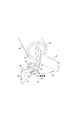
安定化およびレンズを用いない走査
ROIへの治療および診断、ならびに画像化を行うには走査型光ファイバ用に比較的安定な固定台が必要であるため、図10に示すように、走査型光ファイバを身体通路510内で安定化させるためのメカニズムを設けることが時折重要となる。この図を見ると、光ファイバアセンブリ500は、膨張させることのできるバルーン504を含む。このバルーンは、光ファイバアセンブリ内に含まれる管腔部分(図示せず)を通じて膨張する。バルーン504を通路510の両側に接触するように膨張させることにより、光ファイバアセンブリ500の位置が通路に対して固定される。こうすると、この通路の壁部512にあるROI514を画像化することができる。こうして、ROIについて、光ファイバアセンブリの遠位端がROIに対して実質的に移動してしまわないかどうかを気にすることなく、走査型光ファイバで画像化を行い、診断、治療および/または監視機能を行うことができる。しかし、この方法では、呼吸および血流によって多く起こる相対的な組織運動を取り除くことはできない。ROIを安定化させる電子的方法は、対話式タッチセンスディスプレイスクリーン上で画像を電子的に静止させ、タッチ検知型スクリーン上でROIの境界をマークして、画像のセグメンテーションおよび処理用アルゴリズムを処理してそのROIの閾値レベルを記憶するというものである。これらのアルゴリズムを取得した画像上で実行してROIを追跡することにより、正確な治療用途に向けて、相対的な組織運動の間もその境界を固定することができる。
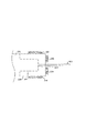
【0079】
上記に開示した走査型光ファイバまたは光導波路の実施形態はそれぞれ画像化レンズまたは走査レンズを含んでいたが、他の実施形態において、画像化レンズも走査レンズも使用しない走査型光ファイバを構成することも可能である。図11A-図11Cに示すように、走査型導波路516が、遠位に澄明なガラス窓502を有し走査型導波路516から発せられた光が直接この窓を介して通路壁部512上に伝送されるようになっている光ファイバアセンブリ501を介して光を伝送する。こうして、光はROI514上に向けて送られる。走査型導波路516から出る光は、低い広がり角または伸張したビームウェスト518を有する。図11Bに示すように、導波路516は、モードの1つで導波路から出た光がROI514の表面全体をカバーできるように、線形か2D状かのいずれかに走査させられる。走査型光ファイバ516は、開きを少なくする、焦点合わせを良好にする、またはコリメートさせることを目的に、高光学性能入力をするための単一モード光ファイバ部分524と、屈折率分布528を得るための、その遠位端に位置する多モード光ファイバ526とを含む。走査型導波路516の遠位端および透明ガラス窓502についてのさらなる詳細は、図11Cに図示されている。
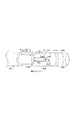
【0080】
剛性内視鏡の走査型光ファイバシステムとの組込み改造
以上から、本発明による走査型光ファイバを、図12に示す内視鏡540など、既存の高解像度剛性内視鏡システムに対する改造物として実施できることがわかった。図12に示すように、光ファイバアセンブリ542は、走査型光ファイバ546の走査動作のために使用するアクチュエータ544(圧電、ピエゾセラミック、または他の電気機械デバイス)を含む。この走査型光ファイバから出た光は、ダイクロイックミラーおよび/または偏光型デバイスであるビームスプリッタ554から反射される。この光は、光の焦点をリレーレンズシステム558内に合わせるレンズ556を介して方向付けられる。リレーレンズシステム558の遠位端に位置する対物レンズ560がその光の焦点をROIの組織562上に合わせる。t1にあるときは、光は対物レンズ560を介して、t1で示す通路に沿って前進し、t2=t1+Δtにあれば、光は異なる通路に沿って前進する。ROIからの光は対物レンズ560およびリレーレンズシステム558、レンズ556、およびビームスプリッタ554を介して通過する。その後、その光の焦点はレンズ564により電荷結合素子(CCD)566内(またはビデオカメラ)に合わせられる。CCDまたはビデオカメラが生成する信号は、リード568を介して外部に伝送され、照明されている組織を画像化できるようにする。さらに、または画像化カメラに代わって、照明光を診断および/または治療用光と組み合わせて、別の光学検出器により時系列で画像化または監視することができる。組織から受け取られる画像化、診断および/または治療用の光は、ビームスプリッタ554により、レンズ552に戻って通過し、フォトダイオード548および/または光ファイバ(図示せず)上に向けて送られる。フォトダイオードは、リード550を介して伝送される信号を生成する。このリードは、光ファイバアセンブリ542を介して光信号の処理に使用する外部計測器まで延在している。走査型光ファイバ546の位置を光学的に追跡するマイクロセンサ570は、走査型光ファイバの走査動作(例えば、位置、速度、周波数など)を正確に決定することにより、より正確で早い走査照明を出力できるようにする信号を提供するものである。
【0081】
従来の剛性内視鏡では、ROIを照明する散乱性白色光照明を得るために、光ファイバのリングを通常用いることを理解されたい。図12の改造型内視鏡では、走査方光ファイバが、画像化、診断および治療に必要な照明すべてを伝送することができる。これまでの実施形態とは異なり、改造型内視鏡における走査型光ファイバは、デバイスの遠位先端部に配置されないため、比較的厳しい寸法上の拘束を受けることがない。この実施形態では、本発明の利点として、ピクセル単位の正確さで高エネルギーレーザ照明に向けて送られること、ガンのスクリーニングおよび他の診断を目的として蛍光画像化および他の診断評価ができること、および、距離測定を実行できることが挙げられる。さらに、光学的治療および組織検出、および放射線量の監視もこのシステムで実行できる。このシステムを可撓性画像化システムの近位端にまで拡張することも考えられるが、そうすると許容範囲を超えるまで光学解像度を損失する可能性がある。図12に示すデバイスでは、フォトダイオード548を、光学的診断の一部として、分光分析、または近位端でコヒーレンスを測定するmad共焦点法(mad confocal)用に光ファイバに置き換えることができる。別法として、高解像度光学走査用に、図示した走査型光ファイバではなく、先細り状または引張られて成形されたガラス製光ファイバまたは薄膜導波路を使用することができる。
【0082】
以上、本発明をその好適実施形態および変形例と併せて記載してきたが、当業者であれば、以下の請求の範囲内において本発明に対して他にも数多くの変更を加えられることは明らかであろう。したがって、本発明の範囲は、上述に何ら制限されるものではなく、特許請求の範囲によってのみ定められるものである。
【図面の簡単な説明】
【図1A】 (従来技術)各検出器が単一画像ピクセルである非走査型可撓性内視鏡の遠位端を示す略図である。
【図1B】 (従来技術)時系列シーケンスで各ピクセルを検出するカンチレバー式走査型光ファイバを示す略図である。
【図1C】 本発明による時系列光子検出器および画像化レンズを有する走査型点源照明装置を示す略図である。
【図1D】 本発明による走査レンズおよび検出器を有する走査型光学ビーム照明装置を示す略図である。
【図2】 本発明による、画像化、監視、診断、および治療を目的として光ファイバと併用可能なシステムにおける信号の機能フローを示すブロック図である。
【図3A】 2つの横断方向の一方または両方に選択的に走査できる直線走査型光ファイバの構成要素を示す図である。
【図3B】 2つの横断方向の一方または両方に選択的に走査できる直線走査型光ファイバの構成要素を示す図である。
【図3C】 画像化レンズを有する、図3Aおよび図3Bの走査型光ファイバを駆動するアクチュエータの一実施形態を示す図である。
【図3D】 走査レンズを有する、図3Aおよび図3Bの走査型光ファイバを駆動するアクチュエータの一実施形態を示す図である。
【図4A】 図3Aおよび図3Bの実施形態に走査機能が類似している薄膜直線型照明装置の第1の実施形態を示す上面図である。
【図4B】 図3Aおよび図3Bの実施形態に走査機能が類似している薄膜直線型照明装置の第1の実施形態を示す、図4Aの線分4B-4Bを通る横断面図である。
【図4C】 図3Aおよび図3Bの実施形態に走査機能が類似している薄膜直線型照明装置の第1の実施形態を示す、図4Aの線分4C-4Cを通る端面図である。
【図4D】 ROIを照明する1対の薄膜平行カンチレバーを含む第2の実施形態を示す立面端図である。
【図5A】 テーパを形成するように微細加工された従来の光ファイバの遠位端であり、真直ぐな状態の遠位端を示す図である。
【図5B】 テーパを形成するように微細加工された従来の光ファイバの遠位端であり、共鳴時に楕円状に偏向した遠位端を示す図である。
【図5C】 走査型光ファイバの3種類の先端部プロファイルに対する相対的PSFを示す図である。
【図5D】 本発明による先細り状光ファイバの可変半径の円形または螺旋走査型モードを示す図である。
【図5E】 光ファイバを駆動できるプロペラ走査モード運動を示す図である。
【図5F】 ボールレンズを嵌合し、第2の機械的共振モードで動作する光ファイバプローブを示す略図である。
【図5G】 図5Fの光ファイバ構造に対する立体的(3D)PSFを示す図である。
【図5H】 光を平行にするために使用するボールレンズが取付けられた光ファイバを示す略図である。
【図6A】 遠位の光ファイバ位置センサと擬似ステレオ画像を取得できる近位光ファイバ集光器を備えて近位に配置された光子検出器との構成を示す略図である。
【図6B】 光ファイバ束と単一同心コア光ファイバとを用いた、近位の光子フィルリングおよび検出用の別法による構成を示す略図である。
【図6C】 光ファイバ束と擬似ステレオ画像を取得できない単一同心コア光ファイバとを用いた、近位における光子フィルリングおよび検出用の別法による構成を示す略図である。
【図6D】 ステレオペア形状と、前方および側方対面式に間隔を置いて配置した検出器を用いて背景散乱光を抜く性能とを利用する、遠位における光子の赤、緑、青(RGB)のフィルタリングおよび検出を示す略側面図である。
【図6E】 ステレオペア形状と、前方および側方対面式に間隔を置いて配置した検出器を用いて背景散乱光を抜く性能とを利用する、遠位における光子の赤、緑、青(RGB)のフィルタリングおよび検出を示す略端図である。
【図6F】 ステレオペア形状と、前方および側方対面式に間隔を置いて配置した検出器を用いて表皮組織からの信号を増強する性能とを利用する、遠位における偏光光子のフィルタリングおよび検出を示す略側面図である。
【図6G】 ステレオペア形状と、前方および側方対面式に間隔を置いて配置した検出器を用いて表皮組織からの信号を増強する性能とを利用する、遠位における偏光光子のフィルタリングおよび検出を示す略端図である。
【図7A】 ダイクロイックフィルタを組み合わせた可視およびUVレーザ源からの放射線を用いる光ファイバシステムを示す略図である。
【図7B】 光ファイバ結合器を直列に接続して組み合わせた可視およびIRレーザ源からの放射線を用いる光ファイバシステムを示す略図である。
【図7C】 先細り状中空チューブを組み合わせた、可変波長レーザ源および標準RGB画像化光源を含む光ファイバシステムを示す略図である。
【図8】 本発明による光ファイバシステムの機能的入力および出力構成要素を示すブロック図である。
【図9A】 本発明による、光学的治療のための出力および監視性能を有する、ガンの画像化、スクリーニング、および生検を行う統合型システムを示す機能ブロック図である。
【図9B】 本発明による、立体画法による外科的サポートおよび表示性能を有する、腫瘍を画像化および診断する統合型システムを示す機能ブロック図である。
【図10】 光ファイバを治療部位に隣接した位置で固定するための膨張させることができるバルーンを有する光ファイバの遠位端を示す側面図である。
【図11A】 光ファイバの遠位端とROIとの間に画像化レンズを含まない光ファイバの一実施形態を示す図である。
【図11B】 光ファイバの遠位端とROIとの間に画像化レンズを含まない光ファイバの一実施形態を示す図である。
【図11C】 光ファイバの遠位端とROIとの間に画像化レンズを含まない光ファイバの一実施形態を示す図である。
【図12】 剛性内視鏡内に組み入れられた本発明の一実施形態を示す横断面図である。[0001]
(Related application)
This application is based on previously co-pending
[0002]
(Field of Invention)
The present invention relates generally to fiber optic systems that transmit light to or from a region of interest (ROI), and more particularly, imaging ROI to facilitate diagnosis and treatment to ROI. It is related with the system selectively used for the purpose of implementation.
[0003]
(Background of the Invention)
The growing area of minimally invasive therapy (MIMP) has a growing demand for systems with less tissue breakage and damage, shorter recovery times, and lower risk to patients. Ideally, MIMP specialists need smaller instruments that can perform more diverse functions. In addition, by adopting the “do it all with one instrument” approach, it guarantees ease of use, ensuring that the learning time for that operation is minimal, so it is simplified rather than complicated. Must be done.
[0004]
Examples of instruments used by MIMP specialists are typically several different and distinct systems intended for optical imaging, monitoring, manipulation, sizing, diagnosis, biopsy, treatment, surgery, and invisible monitoring / sensing Is mentioned. It would be desirable if the functions available with these instruments could be combined into a single small device to reduce the number of surgical ports currently required for multiple single function tools. By using only one small port with an integrated multifunction tool, the risk of repeated surgical tool removal and insertion can be greatly reduced. Optical imaging is considered essential for any integrated system for MIMP, because for most MIMPs, specialists must be constantly monitoring the procedure visually. Thus, a suitable multi-function instrument will generally include an optical imaging system that must be integrated with one or more diagnostic and / or therapeutic tools.
[0005]
Tools currently used for MIMP cannot be easily integrated because their dimensions greatly increase when integrated. All commercially available optical imaging systems that include a steerable flexible shaft cannot change their specific dimensions (diameter) to maintain image quality. Currently, the flexible scope cannot be made smaller than this limit without sacrificing the field of view (FOV) and resolution of the image. Optical systems using current flexible scopes, although imaging and some diagnostic performance can be integrated into existing scopes such as standard tissue imaging combined with fluorescence for early detection of cancer However, it cannot provide integrated diagnosis and treatment with the performance, dimensions, and price that specialists will desire in the future.
[0006]
Current technology used in MIMP
Currently available flexible scopes are designed to use bundles of optical fibers (light guides) and / or one or more cameras with detector arrays that capture images. Therefore, the diameter of the flexible scope used for remote imaging cannot be reduced smaller than the image size. Thus, with the exception of illumination optical fibers, the scope diameter is constrained by the camera pixel size or by the diameter of the optical fiber used to obtain the image. Currently, the minimum pixel element is determined by the end dimensions of the optical fiber, and its minimum core diameter is about 4 μm. Propagating light into the optical fiber requires an enclosing cladding layer, which increases the minimum pixel size diameter to 5 μm or more. If a standard VGA image is desired (eg, 640 × 480 pixel resolution), the minimum diameter required for the image optical fiber alone is 3 mm or more. Therefore, to reduce the overall scope diameter to less than 3 mm, resolution and / or FOV must be sacrificed by reducing the pixel components. All available scopes suffer from this fundamental drag between high image quality and small dimensions.
[0007]
Therefore, it would be desirable to add diagnostic and therapeutic or surgical capabilities to a remote imaging system in order to reduce the overall dimensions of the instrument used for MIMP. For the reasons described above, in current designs, it is not easy to reduce the dimensions of a flexible scope without degrading imaging performance, so to integrate diagnostic and therapeutic applications into an imaging system, Seems to have to be enlarged or a separate instrument must be used for each function. For example, to attach a high intensity light source to a typical endoscopic surgical system to perform photodynamic therapy (PDT) or laser surgery, or to diagnose and / or detect ROI status, Special light sources may be required. However, white light illumination for standard endoscopy imaging is usually obtained through a fiber optic bundle that diffusively illuminates tissue and provides high intensity directed optical energy for effective optical therapy. Cannot be provided in high resolution and may not have the features necessary for the diagnostic process. Therefore, existing optical designs for flexible imaging scopes can be used in both optical treatments that require directed illumination with high-intensity light, such as PDT and laser surgery, and diagnostic processes that require special light sources. Because it cannot be used, it must rely on the second optical path and a separate control mechanism.
[0008]
To perform diagnostic and therapeutic mimps, one or more separate instruments are used in the standard endoscopic imaging device's FOV, and any additional instruments are held and manipulated by a second medical professional. There are many cases that must be done. The second instrument typically provides a high intensity point light source for optical therapy, a probe with a hot tip for thermal therapy, and a trocar used for mechanical cutting. After this second instrument is moved to the tissue surface, it is typically moved within or across the tissue surface to manually cover and cover the region of interest while manually scanning and manipulating the tool. Such secondary instruments are inserted into the patient's body through a separate port and, during use, the visible image is viewed from another viewing point. In addition, with this therapeutic device, the imaging tool often interferes with the specialist's ability to see the ROI directly. This makes it extremely difficult for medical professionals to perform highly accurate treatment. Overcoming this difficulty requires considerable training and practice, and the ability to work with less contact sensation transmitted through the shaft of the instrument having friction and a non-intuitive pivot at the entry point. Thus, to work efficiently with current imaging and treatment techniques, a MIMP specialist must be a highly trained expert.
[0009]
Clearly, there is a need for an instrument that integrates imaging, diagnostic and therapeutic functions to provide these functions via a relatively narrow diameter and requires little training and skill because the usage is intuitive. . Ideally, the instrument can be implemented using a single optical fiber and can provide sufficient FOV, sufficient image size and resolution, and can be used by patients when undergoing treatment. It must be possible to confirm that the ROI in the body corresponds to that at the time of imaging. Currently, this performance is not available from any of the available instruments and cannot be easily modified to obtain.
[0010]
(Summary of Invention)
In accordance with the present invention, a device is defined that selectively provides imaging, monitoring, detection, screening, diagnosis and treatment of patient ROI. The apparatus preferably includes at least one light source. For example, one light source can be used to obtain illumination light for imaging light, and another light source can generate light that is substantially different from imaging light for another application. Alternatively, the same light source can be used for imaging and other purposes. Also included is a light guide having a proximal end and a distal end (the term “light guide” or a plurality thereof is used in the claims below, which term refers to an optical fiber, a thin film optical path, and a desired path) Note that it includes other devices and structures that transmit light along the optical axis.) One or more light sources are optically coupled to the proximal end of the light guide, The distal end of the light guide is adapted to be placed adjacent to the ROI. A scanning actuator is positioned adjacent the distal end of the light guide to cause the ROI to scan with light from one or more light sources transmitted through the light guide. The photodetector receives light from the ROI and generates a signal for use in ROI imaging that corresponds to the intensity of the light. Also included is a display that allows the user to visualize the ROI image and a control circuit operably coupled to control the scanning actuator, one or more light sources, and the light guide. The control circuit selectively energizes one or more light sources to image the ROI and provide at least one other function for the ROI. Examples of other functions include condition diagnosis, therapy delivery, condition sensing, medical procedure monitoring, all of which are done with respect to ROI.
[0011]
In one embodiment of the invention, the plurality of light sources emit light of different colors. The apparatus further includes a combiner that combines the different colored light emitted by the plurality of light sources for inputting the light to the proximal end of the light guide. In addition, for this embodiment, the photodetector includes a plurality of optical sensors that are each sensitive to one of the light of different colors emitted by the plurality of light sources. In one form of this embodiment, the plurality of light sensors are disposed adjacent to the distal end of the light guide, and in another form, the plurality of light guides transmits the imaging light reflected from the ROI to the plurality of lights. Transmit to the sensor. By transmitting the light reflected from the separated regions of the ROI using various portions of the plurality of light guides, the user can visualize the pseudo stereo image of the ROI. Therefore, a stereo display is preferably included so that the user can visualize the pseudo stereo image of the ROI.
[0012]
One form of scanning actuator includes a pair of electromechanical actuators that respectively move the distal end of the light guide in a substantially transverse direction. In another embodiment, the scanning actuator includes a piezoceramic actuator or an electromechanical actuator that is energized with harmonics of the resonant frequency of the distal end of the light guide.
[0013]
In one configuration, the light guide includes an optical fiber, and the distal end of the optical fiber tapers to a substantially narrower cross-sectional dimension than the more proximal portion of the optical fiber, emanating from the non-tapered end of the optical fiber. A tapered end is formed that emits light having a point spread function (PSF) that is substantially smaller than the emitted light.
[0014]
In most embodiments of the present invention, at least one lens is disposed between the distal end of the light guide and the ROI for the purpose of focusing the imaging light and light from the treatment light source on the ROI. The Preferably, to obtain high resolution and sufficient FOV, in one embodiment, a lens is mounted on the distal end of the light guide. In this configuration, when the scanning actuator drives the distal end of the light guide in resonant mode to scan the ROI, the lens attached to the distal end of the light guide has sufficient mass so that As the lens moves, it generally rotates around the center of the lens. As the light guide moves, the direction of the light for scanning the ROI emitted by the lens changes.
[0015]
In yet another embodiment, the light guide includes a thin film optical waveguide that is optically coupled to the distal end of the light guide to direct light emitted by the at least one light source onto the ROI. The scanning actuator is disposed adjacent to the thin film optical waveguide, moves the thin film optical waveguide, and scans the ROI with the light. Preferably, the cross-sectional dimension of the thin film optical waveguide is less than 0.01 mm. It is also conceivable that a plurality of thin film optical waveguides are arranged in parallel to transmit light to and from the ROI.
[0016]
In one embodiment, a polarizing filter is placed between the at least one light source and the ROI to illuminate the ROI with polarized illumination light. In this embodiment, the photodetector detects polarized light having a predetermined polarization axis.
[0017]
In yet another embodiment, the at least one light source provides one or more of visible light, ultraviolet (UV) light, and infrared (IR) light as illumination light. In connection with this embodiment, the photodetector is responsive to one or more of the corresponding visible light, UV light, and / or IR light. In another alternative embodiment, the photodetector is responsive to light emitted by the ROI by phosphorescence or fluorescence.
[0018]
A spectrophotometer or a spectrum analyzer is preferably coupled to the photodetector and used to determine the status of the ROI. Optionally, a thermal detector (which may be an optical type of detector) is coupled to one of the proximal and distal ends of the light guide and used for ROI temperature monitoring.
[0019]
The device also preferably includes means adapted to guide and manipulate the distal end of the light guide into the patient's ROI. When it is necessary to stabilize the distal end of the light guide, a balloon placed adjacent to the distal end of the light guide is inflated in a void or passage in the patient's body.
[0020]
The foregoing aspects of the invention and the many attendant advantages will be better understood and apparent from the following detailed description when taken in conjunction with the accompanying drawings.
[0021]
(Description of Preferred Embodiment)
Conventional imaging endoscope
Referring to FIG. 1A, the distal end of the
[0022]
The time-
[0023]
Scanning device used in the present invention
In contrast to the prior art devices shown in FIGS. 1A and 1B, the present invention does not require separate instrumentation for site imaging and treatment or other functions, but imaging for internal ROI And non-imaging functions such as diagnosis, monitoring and treatment. Many optical diagnostic and therapeutic techniques rely on high-intensity, high-performance illumination, which cannot be done with diffuse illumination because of the unique nature of optical scanning. A strong optical energy scanning beam is more effective in overcoming the signal-to-noise limits of photon detectors used in diagnostic imaging systems. Even when fluorescent dye molecules are used as tracers for specific cells or structures, the signal conversion rate from illumination to fluorescence is very low and often buried in noise. In many therapeutic applications, such as PDT, optically energizing a PDT label on cancerous cells produces free radicals that kill nearby cells. In order to overcome the intrinsic buffering mechanism in the body, a strong optical illumination dose is applied to obtain an effective free radical concentration. Laser treatment that relies on optical heating, cutting and cauterization of tissue requires the most intense light delivered, which cannot be used effectively with diffuse illumination. In order to reduce the damage to surrounding tissue formed by the controlled optical scanning system, the directed light beam must be focused on the tissue for the correct exposure time. Furthermore, high performance illumination can include high optical monochromaticity, coherence, degree of polarization, high modulation frequency, high pulse repetition rate, and short pulse duration.
[0024]
1C and 1D are diagrams illustrating an embodiment of a two-dimensional (2D) scanning point source illumination device. In FIG. 1C, a scanning point
[0025]
Furthermore, the scanning
[0026]
FIG. 1D illustrates a scanning optical
[0027]
In this illumination plane, the optical illumination beam is focused to achieve the desired maximum intensity and / or optical performance in all scanning modes. If the tissue is coincident with this illumination surface, its optical illumination depends on the light power on the tissue and the light spot size. Thus, for imaging, diagnosis and treatment, the resolution of the MIMP is determined by this spot size in the image plane. For image acquisition, this image resolution is determined by the illumination spot size, detector bandwidth (and scan rate), and signal-to-noise ratio (illumination intensity and collection rate), but the physical dimensions of the photon detector. It is not limited by or number.
[0028]
Because diagnosis and treatment must be accurately located, directed illumination that is pre-calibrated before delivery is required. By integrating diagnostic and therapeutic scans into optical imaging, medical professionals can easily identify the optical scan spatially by looking at the displayed image before making a diagnosis or treatment. . Finally, by integrating computer image capture electro-optics and imaging software, image, diagnostic and therapeutic data can be analyzed on a pixel-by-pixel basis. Since each pixel corresponds to the same area or volume of tissue, the integration of a single fiber into the system can spatially align all three functions of imaging, diagnosis and treatment. This single fiber system is highly accurate and can be easily used by a minimally invasive procedure specialist, since all three functions are consistently spatially aligned from the same point.
[0029]
The advantages obtained by using the integrated scanning device of the present invention for the MIME are:
・ The dimensions are smaller by integration,
The price is kept low by integration and the use of low-price components,
・ Because the bending rigidity is lower, the access range in the body is expanded,
・ The time required for the procedure has been shortened, especially when it is necessary to repeat treatment.
The accuracy is further enhanced by integrating the high-resolution imaging device and interactive display;
Additional functions provided by scanning optical systems such as variable resolution (real-time zoom adjustment) and high stereo effects (shading, etc.)
・ Additional functions can be obtained by integrating invisible optical source and detector,
The patient's risk of infection due to multiple tools and multiple incisions is reduced,
・ Because there is little damage to healthy tissue and the amount of anesthesia is small, the patient is expected to recover quickly.
It is.
[0030]
Overview of system processes
Figure 2 shows how the signals generated by the various components in the patient's body are processed by external instruments and how the system control signals are input to the components in the patient's body. A system 50 is shown. In order to provide integrated imaging and other functions, the system 50 is divided into components that are external to the patient's body and components that are used internally (ie, components within the dotted line 52). Block 54 lists functional components located at the distal end of the scanning optical fiber system. As shown in the block, its components include illumination optics, one or more electromechanical scanning actuators, one or more scanner control actuators, one or more scanner motion detection for scanner motion control Instruments, photon detectors for imaging ROI, and optionally additional photon detectors for diagnostic and therapeutic and monitoring purposes. It should be noted that the system 50 can include only functional components that are actually required for a particular application. Further, as an additional function other than imaging, a diagnosis, treatment, or a combination of these functions is possible.
[0031]
Externally, light is supplied to the illumination optical system from the illumination source and modulator as indicated by
[0032]
At
[0033]
At block 64, a data storage device is used to store image data generated by detectors within the patient body and to store other data related to imaging and other functions performed by the scanning optical fiber. Use. Block 64 is also bi-directionally coupled to the computer workstation and interactive display monitor (s) in block 70. Block 70 receives the input from
[0034]
Cantilever scanning optical fiber
A “zig-zag” or linear scanning
[0035]
The zigzag or linear embodiment shown in FIGS. 3A and 3B is preferred compared to other embodiments disclosed below because the physical dimensions are substantially larger and the photon detector must be moved. is not. For example, the diameter of the cantilever
[0036]
An optical fiber can be operated in a scanning mode using a scanning actuator other than a piezoelectric actuator. For example, FIG. 3C illustrates a scanning
[0037]
The cantilevered optical fiber passes through the
[0038]
In FIG. 3D, yet another
[0039]
Embodiment of scanning thin-film optical waveguide
By producing a scanning optical fiber that is narrower than the cross-sectional area shown in the embodiment of FIGS. 3A and 3B, and making such a device more economical by making it relatively inexpensive and small in volume, it can be used as a disposable device. It should be understood that it would be desirable to facilitate the widespread use of. Microelectromechanical system (MEMS) technology uses thin film devices in conjunction with integrated actuators to achieve these goals. 4A, 4B and 4C illustrate an initial prototype of the thin film
[0040]
In this thin film optical device, an
[0041]
4A and 4B show an embodiment in which the
[0042]
Tapered and other scanning optical fibers
Other techniques can be used to form a relatively small illumination PSF. For example, as shown in FIGS. 5A and 5B, a conventional
[0043]
As shown in FIG. 5C, the relative PSF and FOV for the various forms of optical fiber vary depending on the nature of the location of the distal end of the optical fiber that emits light toward the
[0044]
Other scanning modes different from the linear mode, linear or zigzag mode described above can also be realized. FIG. 5D illustrates a variable radius or helical scan mode of the fiber
[0045]
A series of variable radius circles are drawn by the optical fiber in the circular scan mode, and the optical fiber in the spiral scan mode performs a helical scan with increasing and decreasing radii. In this circular or helical scan mode, the distal end of the
[0046]
To maximize the total number of pixels across the maximum FOV for imaging, diagnosis and treatment, the lens system must form a diffraction limited spot for illumination. Assuming an ideal scanning optical fiber, the spatial resolution of the output illumination is limited by the projected light source size and the diffraction- or aberration-limited performance of the lens system. For optical systems with limited aberrations, the main purpose of placing a secondary imaging lens or
[0047]
Accordingly, FIG. 5F shows the
[0048]
Theoretically, only a single photodetector is required to collect backscattered scanning light and form a monochrome or black and white image. A simple way to generate a full-color image is to use three photodetectors (as described above) each covered with different filters selected to transmit blue, green or red light transmission. is there. For the detection of visible light and near IR light, a semiconductor photodiode (Si-PIN type or the like) mainly composed of silicon is suitable because of its high sensitivity, low cost, small size, high speed, and robustness. Photodiodes commonly used in the communications industry, such as InGaAs material photodiodes, are suitable for embodiments of the present invention that detect IR light. The resolution of integrated optical scanning technology is not dependent on the size and number of photodetectors, so it can be used at the distal end of a fiber optic assembly for the purpose of amplifying and distinguishing between signal levels All of the space is covered by a photodetector. As will become more apparent in the description below, the photodetector, preferably the optical axis, should be improved so that the image quality of the ROI geometric features (such as shade) can be enhanced and glare from spectral reflections can be eliminated. A stereo pair is provided at the center. When IR radiation is used in combination with visible light, multiple photodetectors with different photosensitive materials can be used without a filter (not shown). An alternative method of separating the spectral response of the unfiltered detector must synchronize the detector signal with a suitable illumination source having a pulse output. For example, if an RGB laser or other light source is each pulsed in rapid time series and synchronized with the signal processing received from the photodetector, the same visible light detector can be used without a filter.
[0049]
[0050]
A detailed description of the operation of an
[0051]
Optical fiber systems for imaging and spectral or polarization analysis
FIG. 6A illustrates a
[0052]
Another system 271 according to the present invention is illustrated in FIG. 6B. In system 271,
[0053]
To control the scanning of the optical fiber, additional optical detectors and emitters are used adjacent (in parallel or adjacent) to the scanning optical fiber so that the movement and position (or position) of the optical fiber distal tip over time (or Frequency and speed) can be detected. As shown in FIG. 6A, when the optical fiber is bent more sharply and the amount of light leakage increases, it can be detected by the
[0054]
In FIG. 6B, an
[0055]
The spatial resolution of a scanning fiber optic system that emits directed illumination for treatment depends on the number of identifiable spots of light that can be projected onto the illuminated image plane. The resolution depends on the minimum spot size, and the FOV depends on the maximum scanning angle (total number of identifiable spots). When an image is acquired, the spatial resolution also depends on the photon detector bandwidth (assuming a sufficient signal-to-noise ratio) and the total number of pixels available to the display system. By operating within the bandwidth limits of the scanning system components, the resolution and FOV can be dynamically changed to perform functions such as ROI display magnification and dynamic magnification changes. In many applications, both the ROI and single fiber optic system are stationary (other than the distal end of the scanning optical fiber), so the rate of blurring due to scanning is well below the playback rate of the display device. descend. By scanning slower than the standard video capture rate, the optical system can provide higher power to the optical therapy and integrate the signal from the weak fluorescent diagnosis of the signal over a longer period of time. Thus, the dynamic range of the scanning optical system can be optimized according to system components and application requirements.
[0056]
Only one or a few pixels of illumination can be emitted per frame. For example, with the present invention, real-time optical biopsy can be performed at a point in the ROI, very bright excitation light can be used, and spectroscopic acquisition and spectral mapping for normal images can be obtained. It is done.
[0057]
FIG. 6C shows a portion of a concentric
[0058]
6D and 6E illustrate an embodiment including detectors for RGB, UV and IR spectral components. The
[0059]
6F and 6G show an
[0060]
FIG. 7A schematically illustrates a
[0061]
An alternative
[0062]
In FIG. 7C, a multi-spectral component
[0063]
Functional block diagram
FIG. 8 illustrates various functions that can be implemented in the present invention. Functions such as diagnosis, treatment and monitoring are shown by blocks surrounded by dotted lines, and solid lines are used for the imaging function of the
[0064]
In addition, image analysis software for performing spectral and multivariate analysis and locating and calculating boundaries of the region of interest is executed using a computer workstation or other computing device. For ROI, the calculation can identify its distribution, boundary, volume, color and optical density, as well as determine the disease state, medical staging of the tissue based on the data collected from the ROI, and therapeutic Radiation dose can be calculated and monitored. All of these functions are shown in
[0065]
Thus, various embodiments of optical fiber scanning actuators have been described.
[0066]
Details of various functions that can be implemented in the present invention are described below.
[0067]
Integrated imaging, screening and diagnostics
Optical tissue imaging using UV, visible and IR wavelengths
・ Fluorescence imaging using UV, visible and IR wavelengths
・ Thermal imaging using IR wavelengths
・ Deep tissue imaging using IR wavelength
Concentric confocal and true confocal imaging
・ Imaging via blood using IR wavelength
・ Imaging by polarization contrast
・ Microscopic inspection by laser feedback
Optical interference tomography (OCT) and optical interference reflectometry (OCR)
・ Vibro-acoustic analysis by optical induction
・ High resolution and high magnification tissue contact imaging
Imaging and detection with laser-induced fluorescence (LIF) and ratio fluorescence
・ Imaging by multiphoton excitation fluorescence
・ Imaging and analysis by fluorescence lifetime
-True size adjustment of image structure using stereo range finder option
・ Laser-induced fluorescence spectroscopy (LIFS)
・ Raman spectroscopy
・ Elastic scattering spectroscopy (ESS) analysis
・ Absorption spectroscopy
Chemiluminescence and cell viability detection and mapping
・ Spatial mapping of optical sensor data (oxygen concentration, pH, ion concentration, etc.)
・ Temperature measurement and feedback control
Other measurements for color, laser power delivery, tissue performance, photobleaching, and compound photocreation for monitoring and feedback purposes
[0068]
Treatment, surgery and monitoring
・ Photodynamic therapy (PDT)
Heating to tissues and / or tumors (eg hyperthermia)
Laser surgery with optical illumination (UV, heating and / or ablation)
・ Photoactivation of chemical reactions, photopolymerization, and transplantation of biomaterials
・ Laser ablation (optically or electronically heated) by high-temperature tip of scanner
・ Mechanical destruction of tissues using shock waves generated by absorption of optical pulse irradiation
[0069]
Interactive display and advanced user interface design
・ Pseudo stereo on display monitor, mapping by stereoscopic method using superimposition of pseudo color, and true 3D display format (Note: The strategy and performance of each display varies depending on the specific application.)
-Interactive touch / pointing screen (point screen)
[0070]
FIGS. 9A and 9B show other functions that can be performed with the present invention that vary depending on the instrument used. FIG. 9A shows a single scanning waveguide used for imaging, sampling, diagnosis and treatment delivery, and FIG. 9B for 3D imaging, performing a tumor biopsy, and monitoring
[0071]
One of the two displays could be a touch screen monitor that allows the specialist to select (outline) the ROI for laser surgery. Because this image may be movable, the touch screen monitor must be capable of capturing the image and temporarily stopping it. However, once this ROI outline is drawn, the algorithm for image segmentation and object recognition can be implemented to highlight the ROI during real-time image acquisition and display. In touch screen monitors, specialists can utilize sidebar menus to set laser therapy parameters such as power level and laser radiation exposure time. The second display may not be interactive, but is preferably a high resolution monitor that displays real-time optical images in full color or gray scale. When the IR photon detector is integrated with the endoscope, a high-resolution display using pseudo-color is obtained, allowing specialists to proceed with laser treatments such as tissue heating and / or tissue irradiation in laser surgery. The condition can be monitored.
[0072]
As shown in
[0073]
To facilitate control of the operation of the scanning optical fiber or optical waveguide, as shown in
[0074]
In using the
[0075]
If optical therapy such as PDT is approved, determine the optical radiation dose and program an interactive computer workstation that controls the manipulating fiber optic system. The PDT treatment is optically scanned with high intensity laser illumination by a high
[0076]
Referring to FIG. 9B, a
[0077]
When using the
[0078]
Stabilization and scanning without lens
ROI treatment and diagnostics and imaging require a relatively stable fixture for the scanning optical fiber, so the scanning optical fiber is stable in the
[0079]
While the embodiments of the scanning optical fiber or optical waveguide disclosed above each included an imaging lens or scanning lens, in other embodiments, a scanning optical fiber that uses neither an imaging lens nor a scanning lens is configured. It is also possible. As shown in FIGS. 11A-11C, the
[0080]
Retrofit of rigid endoscope with scanning optical fiber system
From the above, it has been found that the scanning optical fiber according to the present invention can be implemented as a modification to an existing high-resolution rigid endoscope system such as the
[0081]
It should be understood that conventional rigid endoscopes typically use a fiber optic ring to obtain diffuse white light illumination that illuminates the ROI. In the modified endoscope of FIG. 12, the scanning optical fiber can transmit all the illumination necessary for imaging, diagnosis and treatment. Unlike previous embodiments, the scanning optical fiber in a modified endoscope is not placed at the distal tip of the device and is therefore not subject to relatively strict dimensional constraints. In this embodiment, the advantages of the present invention include being directed towards high energy laser illumination with pixel accuracy, being capable of fluorescence imaging and other diagnostic evaluations for cancer screening and other diagnostic purposes, and , Distance measurement can be performed. In addition, optical therapy and tissue detection, and radiation dose monitoring can also be performed with this system. It is conceivable to extend this system to the proximal end of the flexible imaging system, but this can result in loss of optical resolution until it is beyond acceptable limits. In the device shown in FIG. 12, the
[0082]
Although the present invention has been described in conjunction with preferred embodiments and modifications thereof, it will be apparent to those skilled in the art that many other modifications can be made to the present invention within the scope of the following claims. Will. Therefore, the scope of the present invention is not limited to the above, but is defined only by the claims.
[Brief description of the drawings]
FIG. 1A (Prior Art) is a schematic showing the distal end of a non-scanning flexible endoscope where each detector is a single image pixel.
FIG. 1B (Prior Art) is a schematic diagram showing a cantilever-type scanning optical fiber that detects each pixel in a time-series sequence.
1C is a schematic diagram illustrating a scanning point source illumination device having a time-series photon detector and an imaging lens according to the present invention. FIG.
1D is a schematic diagram illustrating a scanning optical beam illumination device having a scanning lens and a detector according to the present invention. FIG.
FIG. 2 is a block diagram illustrating the functional flow of signals in a system that can be used with optical fiber for imaging, monitoring, diagnosis, and treatment purposes in accordance with the present invention.
FIG. 3A illustrates components of a linear scanning optical fiber that can be selectively scanned in one or both of two transverse directions.
FIG. 3B illustrates components of a linear scanning optical fiber that can be selectively scanned in one or both of two transverse directions.
3C illustrates one embodiment of an actuator that drives the scanning optical fiber of FIGS. 3A and 3B with an imaging lens. FIG.
3D illustrates one embodiment of an actuator for driving the scanning optical fiber of FIGS. 3A and 3B having a scanning lens. FIG.
4A is a top view showing a first embodiment of a thin-film linear illumination device having a scanning function similar to the embodiment of FIGS. 3A and 3B. FIG.
4B is a cross-sectional view through
4C is an end view through
4D is an elevational view showing a second embodiment including a pair of thin film parallel cantilevers that illuminate the ROI. FIG.
FIG. 5A is a distal end of a conventional optical fiber micromachined to form a taper, showing the straight distal end.
FIG. 5B is a view of the distal end of a conventional optical fiber micromachined to form a taper, deflected elliptically during resonance.
FIG. 5C is a diagram showing a relative PSF with respect to three types of tip end profiles of a scanning optical fiber.
FIG. 5D shows a variable radius circular or spiral scanning mode of a tapered optical fiber according to the present invention.
FIG. 5E illustrates propeller scan mode motion that can drive an optical fiber.
FIG. 5F is a schematic diagram showing an optical fiber probe fitted with a ball lens and operating in a second mechanical resonance mode.
FIG. 5G shows a three-dimensional (3D) PSF for the optical fiber structure of FIG. 5F.
FIG. 5H is a schematic diagram showing an optical fiber fitted with a ball lens used to collimate light.
FIG. 6A is a schematic diagram illustrating the configuration of a distal fiber optic position sensor and a proximally located photon detector with a proximal fiber optic concentrator capable of acquiring pseudo-stereo images.
6B is a schematic diagram illustrating an alternative configuration for proximal photon filling and detection using an optical fiber bundle and a single concentric core optical fiber. FIG.
FIG. 6C is a schematic diagram illustrating an alternative configuration for proximal photon filling and detection using a fiber optic bundle and a single concentric core optical fiber that cannot acquire pseudo-stereo images.
FIG. 6D. Distal photon red, green, blue (RGB) utilizing stereo pair geometry and the ability to extract background scattered light using detectors spaced forward and side-to-side. ) Is a schematic side view showing filtering and detection.
FIG. 6E. Photon red, green, blue (RGB) at the distal end utilizing the stereo pair shape and the ability to extract background scattered light using detectors spaced forward and side-to-side. ) Is a schematic end view showing filtering and detection.
FIG. 6F. Filtering and detection of polarized photons at the distal utilizing the stereo pair shape and the ability to enhance signals from epidermal tissue using anteriorly and laterally spaced detectors. FIG.
FIG. 6G. Filtering and detection of polarized photons at the distal utilizing the stereo pair shape and the ability to enhance signals from epidermal tissue using detectors spaced forward and side-to-side. FIG.
FIG. 7A is a schematic diagram showing an optical fiber system using radiation from visible and UV laser sources in combination with a dichroic filter.
FIG. 7B is a schematic diagram showing an optical fiber system using radiation from visible and IR laser sources combined with serially connected optical fiber couplers.
FIG. 7C is a schematic diagram showing an optical fiber system including a variable wavelength laser source and a standard RGB imaging light source combined with a tapered hollow tube.
FIG. 8 is a block diagram illustrating functional input and output components of an optical fiber system according to the present invention.
FIG. 9A is a functional block diagram illustrating an integrated system for imaging, screening and biopsying cancer with output and monitoring capabilities for optical therapy according to the present invention.
FIG. 9B is a functional block diagram illustrating an integrated system for imaging and diagnosing tumors with stereoscopic support and display capabilities according to the present invention.
FIG. 10 is a side view of the distal end of an optical fiber having an inflatable balloon for securing the optical fiber in a position adjacent to a treatment site.
FIG. 11A illustrates one embodiment of an optical fiber that does not include an imaging lens between the distal end of the optical fiber and the ROI.
FIG. 11B illustrates one embodiment of an optical fiber that does not include an imaging lens between the distal end of the optical fiber and the ROI.
FIG. 11C illustrates one embodiment of an optical fiber that does not include an imaging lens between the distal end of the optical fiber and the ROI.
FIG. 12 is a cross-sectional view illustrating one embodiment of the present invention incorporated into a rigid endoscope.
Claims (35)
(a)光を発する少なくとも1つの光源と、
(b)前記少なくとも1つの光源が光学的に結合されている近位端と、関心領域に隣接して配置されるように適合されている遠位端とを有する光ガイドと、
(c)前記少なくとも1つの光源から発せられて前記光ガイド内を伝送された光に関心領域を走査させる、前記光ガイドの前記遠位端に隣接して配置される走査アクチュエータであって、前記光ガイドが含む前記遠位端の共振周波数の調波にて付勢されて前記光ガイドを振動させるピエゾセラミックアクチュエータを含む走査アクチュエータと、
(d)関心領域の画像形成に使用するため、関心領域からの光を受け取り、前記光の強度に対応する信号を生成する光検出器と、
(e)ユーザが関心領域の画像を可視化できるように適合されているディスプレイと、
(f)前記走査アクチュエータ、前記少なくとも1つの光源、および前記光ガイドを制御するように結合され、前記少なくとも1つの光源を付勢して、関心領域を画像化し、かつ状態の診断、治療の実施、状態の検出、および状態の監視の少なくとも1つを含む少なくとも1つの機能を関心領域に対して行わせる制御回路と
を備えることを特徴とする装置。An apparatus that selectively provides imaging and at least one other function for a region of interest within a patient comprising:
(a) at least one light source that emits light;
(b) a light guide having a proximal end to which the at least one light source is optically coupled and a distal end adapted to be positioned adjacent to the region of interest;
(c) a scanning actuator disposed adjacent to the distal end of the light guide that causes light emitted from the at least one light source and transmitted through the light guide to scan a region of interest; A scanning actuator including a piezoceramic actuator that is energized by harmonics of a resonance frequency of the distal end included in the light guide to vibrate the light guide;
(d) a photodetector that receives light from the region of interest and generates a signal corresponding to the intensity of the light for use in imaging the region of interest;
(e) a display adapted to allow the user to visualize an image of the region of interest;
(f) coupled to control the scanning actuator, the at least one light source, and the light guide, energizing the at least one light source to image a region of interest, and perform a state diagnosis, treatment And a control circuit for performing at least one function on the region of interest including at least one of state detection and state monitoring.
(b)前記関心領域と少なくとも1つの光センサとの間
の少なくとも一方に配置されるように適合されている偏光フィルタをさらに備えることを特徴とする請求項3に記載の装置。(a) between the at least one light source and the region of interest such that the region of interest is illuminated with polarized illumination light; and
4. The apparatus of claim 3, further comprising (b) a polarizing filter adapted to be disposed in at least one between the region of interest and at least one photosensor.
(a)光源と、
(b)前記光源に光学的に結合され、近位端および遠位端を有し、前記光源が発する光を患者の身体内の関心領域に伝送するように適合された光ガイドと、
(c)前記光ガイドの前記遠位端に隣接して配置され、前記光ガイドに結合されて、前記光ガイド内に伝送された光が関心領域上に走査パターンを形成するように、前記光ガイドの前記遠位端を移動させるように適合された走査アクチュエータと
を備え、前記走査アクチュエータは、前記光ガイドの前記遠位端の共振周波数の調波にて付勢されて前記光ガイドを振動させるピエゾセラミックアクチュエータを含むことを特徴とする装置。A device for automatically scanning a region of interest within a patient's body,
(a) a light source;
(b) a light guide optically coupled to the light source and having a proximal end and a distal end and adapted to transmit light emitted by the light source to a region of interest within a patient's body;
(c) the light disposed adjacent to the distal end of the light guide and coupled to the light guide such that the light transmitted in the light guide forms a scanning pattern on a region of interest. A scanning actuator adapted to move the distal end of the guide, wherein the scanning actuator is biased at harmonics of a resonance frequency of the distal end of the light guide to vibrate the light guide A device comprising a piezoceramic actuator.
Applications Claiming Priority (3)
| Application Number | Priority Date | Filing Date | Title |
|---|---|---|---|
| US21241100P | 2000-06-19 | 2000-06-19 | |
| US60/212,411 | 2000-06-19 | ||
| PCT/US2001/016844 WO2001097902A2 (en) | 2000-06-19 | 2001-05-23 | Medical imaging, diagnosis, and therapy using a scanning single optical fiber system |
Publications (3)
| Publication Number | Publication Date |
|---|---|
| JP2003535659A JP2003535659A (en) | 2003-12-02 |
| JP2003535659A5 JP2003535659A5 (en) | 2008-07-03 |
| JP5025877B2 true JP5025877B2 (en) | 2012-09-12 |
Family
ID=22790900
Family Applications (1)
| Application Number | Title | Priority Date | Filing Date |
|---|---|---|---|
| JP2002503383A Expired - Lifetime JP5025877B2 (en) | 2000-06-19 | 2001-05-23 | Medical imaging, diagnosis and treatment using a scanning single fiber optic system |
Country Status (4)
| Country | Link |
|---|---|
| US (1) | US6975898B2 (en) |
| JP (1) | JP5025877B2 (en) |
| AU (1) | AU2001274933A1 (en) |
| WO (1) | WO2001097902A2 (en) |
Cited By (3)
| Publication number | Priority date | Publication date | Assignee | Title |
|---|---|---|---|---|
| US11047671B1 (en) | 2020-01-30 | 2021-06-29 | Veravanti Inc. | Forward looking RGB/optical coherence tomography duplex imager |
| US11484192B2 (en) | 2017-01-27 | 2022-11-01 | Olympus Corporation | Optical-scanning-type observation probe and optical-scanning-type observation device |
| US12385733B2 (en) | 2020-01-30 | 2025-08-12 | Soham Inc. | Synchronizing an optical coherence tomography system |
Families Citing this family (615)
| Publication number | Priority date | Publication date | Assignee | Title |
|---|---|---|---|---|
| US6185443B1 (en) | 1997-09-29 | 2001-02-06 | Boston Scientific Corporation | Visible display for an interventional device |
| US10973397B2 (en) | 1999-03-01 | 2021-04-13 | West View Research, Llc | Computerized information collection and processing apparatus |
| US8636648B2 (en) | 1999-03-01 | 2014-01-28 | West View Research, Llc | Endoscopic smart probe |
| US6563105B2 (en) * | 1999-06-08 | 2003-05-13 | University Of Washington | Image acquisition with depth enhancement |
| US7134557B2 (en) * | 2000-02-04 | 2006-11-14 | Bratten Jack R | Lift station and method |
| JP2001282140A (en) * | 2000-03-31 | 2001-10-12 | Sony Corp | Information reception display device |
| US7555333B2 (en) | 2000-06-19 | 2009-06-30 | University Of Washington | Integrated optical scanning image acquisition and display |
| US6975898B2 (en) * | 2000-06-19 | 2005-12-13 | University Of Washington | Medical imaging, diagnosis, and therapy using a scanning single optical fiber system |
| JP4662515B2 (en) * | 2000-09-22 | 2011-03-30 | セイコーインスツル株式会社 | Medical module equipment |
| JP2002095634A (en) * | 2000-09-26 | 2002-04-02 | Fuji Photo Film Co Ltd | Endoscope system |
| DE60141090D1 (en) | 2000-10-30 | 2010-03-04 | Gen Hospital Corp | OPTICAL SYSTEMS FOR TISSUE ANALYSIS |
| US6856712B2 (en) * | 2000-11-27 | 2005-02-15 | University Of Washington | Micro-fabricated optical waveguide for use in scanning fiber displays and scanned fiber image acquisition |
| DE10062187B4 (en) * | 2000-12-14 | 2005-08-04 | Schott Ag | Use of a device for ceramizing the starting glass of a glass ceramic |
| US8078262B2 (en) * | 2001-04-16 | 2011-12-13 | The Johns Hopkins University | Method for imaging and spectroscopy of tumors and determination of the efficacy of anti-tumor drug therapies |
| US7349098B2 (en) * | 2001-05-07 | 2008-03-25 | University Of Washington | Simultaneous beam-focus and coherence-gate tracking for real-time optical coherence tomography |
| US7616986B2 (en) * | 2001-05-07 | 2009-11-10 | University Of Washington | Optical fiber scanner for performing multimodal optical imaging |
| US8078268B2 (en) | 2001-06-28 | 2011-12-13 | Chemimage Corporation | System and method of chemical imaging using pulsed laser excitation and time-gated detection to determine tissue margins during surgery |
| US6954667B2 (en) * | 2001-06-28 | 2005-10-11 | Chemimage Corporation | Method for Raman chemical imaging and characterization of calcification in tissue |
| DE10145167C2 (en) * | 2001-09-13 | 2003-07-24 | Siemens Dematic Ag | Optical distance switch and placement head, placement machine and method for placing substrates with components using the optical distance switch |
| US20030128175A1 (en) * | 2002-01-09 | 2003-07-10 | International Business Machines Corporation | Stereoscopic display system and method |
| US8423110B2 (en) * | 2002-01-09 | 2013-04-16 | Boston Scientific Scimed, Inc. | Imaging device and related methods |
| GB2385735B (en) * | 2002-02-21 | 2003-12-31 | Keymed | Image capture and display system |
| US20040082863A1 (en) * | 2002-03-15 | 2004-04-29 | Mcgreevy James | Device and method for the photodynamic diagnosis of tumor tissue |
| US9155544B2 (en) * | 2002-03-20 | 2015-10-13 | P Tech, Llc | Robotic systems and methods |
| US7405854B2 (en) * | 2002-03-21 | 2008-07-29 | Cornell Research Foundation, Inc. | Fibrous micro-composite material |
| US20040010204A1 (en) * | 2002-03-28 | 2004-01-15 | Pearl Technology Holdings, Llc | Electronic/fiberoptic tissue differentiation instrumentation |
| AU2003241557A1 (en) * | 2002-05-17 | 2003-12-02 | Arete Associates | Micromechanical and related lidar apparatus and method, and fast light-routing components |
| US7257437B2 (en) * | 2002-07-05 | 2007-08-14 | The Regents Of The University Of California | Autofluorescence detection and imaging of bladder cancer realized through a cystoscope |
| US8285015B2 (en) | 2002-07-05 | 2012-10-09 | Lawrence Livermore Natioonal Security, LLC | Simultaneous acquisition of differing image types |
| US6904199B2 (en) * | 2002-08-14 | 2005-06-07 | Infraredx, Inc. | Optical catheter with double-clad fiber |
| WO2004036705A1 (en) * | 2002-10-17 | 2004-04-29 | Lumenis Inc. | System, method, and apparatus to provide laser beams of two or more wavelengths |
| WO2004040267A1 (en) * | 2002-10-30 | 2004-05-13 | Optiscan Pty Ltd | Scanning method and apparatus |
| US6879741B2 (en) | 2002-11-04 | 2005-04-12 | C Technologies, Inc | Sampling end for fiber optic probe |
| US7252634B2 (en) * | 2002-11-05 | 2007-08-07 | Pentax Corporation | Confocal probe having scanning mirrors mounted to a transparent substrate in an optical path of the probe |
| US20040111032A1 (en) * | 2002-12-04 | 2004-06-10 | Jeff Korn | Optical coupler for rotating catheter |
| US7616321B2 (en) * | 2002-12-04 | 2009-11-10 | Infraredx, Inc. | Optical coupler for rotating catheter |
| US7634305B2 (en) * | 2002-12-17 | 2009-12-15 | Given Imaging, Ltd. | Method and apparatus for size analysis in an in vivo imaging system |
| FR2849218B1 (en) * | 2002-12-20 | 2005-03-04 | Mauna Kea Technologies | CONFOCAL OPTICAL HEAD, IN PARTICULAR MINIATURE, INTEGRATED SCANNING AND CONFOCAL IMAGING SYSTEM IMPLEMENTING SAID HEAD |
| US7068878B2 (en) * | 2003-01-24 | 2006-06-27 | University Of Washington | Optical beam scanning system for compact image display or image acquisition |
| US7354433B2 (en) * | 2003-02-28 | 2008-04-08 | Advanced Light Technologies, Llc | Disinfection, destruction of neoplastic growth, and sterilization by differential absorption of electromagnetic energy |
| US20110040295A1 (en) * | 2003-02-28 | 2011-02-17 | Photometics, Inc. | Cancer treatment using selective photo-apoptosis |
| US20060239673A1 (en) * | 2003-03-13 | 2006-10-26 | Roke Manor Research Limited | Camera illumination system |
| JP2006524091A (en) | 2003-04-24 | 2006-10-26 | コーニンクレッカ フィリップス エレクトロニクス エヌ ヴィ | Catheter head |
| US7844321B2 (en) * | 2003-04-28 | 2010-11-30 | Board Of Regents, The University Of Texas System | Rotating catheter probe using a light-drive apparatus |
| JP4690331B2 (en) * | 2003-05-14 | 2011-06-01 | スペクトラキュア アクティエボラーグ | System and method for treatment and diagnosis with a translation distributor for radiation delivery |
| ATE547043T1 (en) * | 2003-05-14 | 2012-03-15 | Spectracure Ab | TREATMENT AND DIAGNOSIS SYSTEM USING COMBINED NON-MECHANICAL AND MECHANICAL DISTRIBUTORS FOR DISTRIBUTING RADIATION |
| SE527164C2 (en) * | 2003-05-14 | 2006-01-10 | Spectracure Ab | Interactive therapy/diagnosis system for tumor, has operation mode selector to optically direct non-ionizing electromagnetic therapeutic and/or diagnostic radiation to tumor site, through radiation conductor |
| KR20060033860A (en) * | 2003-05-29 | 2006-04-20 | 리젠츠 오브 더 유니버시티 오브 미시간 | Double coated fiber scanning microscope |
| CN100457020C (en) * | 2003-06-23 | 2009-02-04 | 微视公司 | scanning endoscope |
| US7448995B2 (en) * | 2003-06-23 | 2008-11-11 | Microvision, Inc. | Scanning endoscope |
| US20050008253A1 (en) * | 2003-07-10 | 2005-01-13 | Joseph Rozgonyi | Method and apparatus for eliminating irrelevant luminescent signals |
| US20050027163A1 (en) * | 2003-07-29 | 2005-02-03 | Scimed Life Systems, Inc. | Vision catheter |
| US20050027164A1 (en) * | 2003-07-29 | 2005-02-03 | Scimed Life Systems, Inc. | Vision catheter |
| US7030383B2 (en) * | 2003-08-04 | 2006-04-18 | Cadent Ltd. | Speckle reduction method and apparatus |
| SE0302237L (en) * | 2003-08-19 | 2004-10-19 | Saab Ab | Breathing mask with presentation device |
| US8190231B2 (en) | 2003-11-20 | 2012-05-29 | Hamamatsu Photonics K.K. | Lymph node detecting apparatus |
| EP1691666B1 (en) * | 2003-12-12 | 2012-05-30 | University of Washington | Catheterscope 3d guidance and interface system |
| FR2864438B1 (en) * | 2003-12-31 | 2006-11-17 | Mauna Kea Technologies | MINIATURE INTEGRATED SCANNING OPTICAL HEAD FOR REALIZING A HOMOGENEOUS CONFOCAL IMAGE, AND CONFOCAL IMAGING SYSTEM USING THE SAME |
| US7088239B2 (en) * | 2004-03-02 | 2006-08-08 | Vann Basinger | Method and apparatus for all-purpose, automatic remote utility meter reading, utility shut off, and hazard warning and correction |
| US7273452B2 (en) * | 2004-03-04 | 2007-09-25 | Scimed Life Systems, Inc. | Vision catheter system including movable scanning plate |
| US7804075B2 (en) * | 2004-03-11 | 2010-09-28 | The General Hospital Corporation | Method and system for tomographic imaging using fluorescent proteins |
| SE0400817D0 (en) * | 2004-03-30 | 2004-03-30 | Benf Ab | Arrangement and method for determining muscular contractions in an anatomical organ |
| DE102004016422B4 (en) * | 2004-04-02 | 2007-08-30 | Beck, Tobias, Dipl.-Phys. | Device with at least one optical fiber bundle unit for location marking, remission and fluorescence measurement |
| CN100570429C (en) | 2004-06-24 | 2009-12-16 | 康乃尔研究基金会有限公司 | MEMS optical scanner based on fiber composite material |
| JP2006014868A (en) | 2004-06-30 | 2006-01-19 | Hamamatsu Photonics Kk | Lymph node detecting apparatus |
| AU2005270037B2 (en) | 2004-07-02 | 2012-02-09 | The General Hospital Corporation | Endoscopic imaging probe comprising dual clad fibre |
| FR2872909B1 (en) * | 2004-07-07 | 2008-11-14 | Centre Nat Rech Scient Cnrse | METHOD AND SYSTEM FOR OPTICALLY DETECTING NANO-OBJECTS IN A REFRINGENT ENVIRONMENT |
| US8152305B2 (en) | 2004-07-16 | 2012-04-10 | The University Of North Carolina At Chapel Hill | Methods, systems, and computer program products for full spectrum projection |
| KR20070064319A (en) | 2004-08-06 | 2007-06-20 | 유니버시티 오브 워싱톤 | Variable Stare Viewing Scanning Optical Display |
| KR101215005B1 (en) * | 2004-08-20 | 2012-12-24 | 마이클 알. 보레르 | Control device made of impact resistant material |
| WO2006024015A1 (en) | 2004-08-24 | 2006-03-02 | The General Hospital Corporation | Method and apparatus for imaging of vessel segments |
| US20060095065A1 (en) * | 2004-09-24 | 2006-05-04 | Tetsuaki Tanimura | Fluid occluding devices and methods |
| US8929688B2 (en) * | 2004-10-01 | 2015-01-06 | University Of Washington | Remapping methods to reduce distortions in images |
| US7298938B2 (en) * | 2004-10-01 | 2007-11-20 | University Of Washington | Configuration memory for a scanning beam device |
| EP1805779A4 (en) * | 2004-10-01 | 2009-07-01 | Univ Washington | REMAPPING METHODS FOR REDUCING DISTORTIONS IN IMAGES |
| EP3955036B1 (en) | 2004-10-01 | 2024-02-21 | University of Washington | Method of operating a scanning beam device with a configuration memory |
| JP5367267B2 (en) * | 2004-11-26 | 2013-12-11 | ロレアル | How to observe biological tissue, especially human skin |
| FR2878424B1 (en) | 2004-11-26 | 2008-02-01 | Oreal | METHOD FOR OBSERVING A BIOLOGICAL TISSUE, IN PARTICULAR HUMAN SKIN |
| US8922781B2 (en) | 2004-11-29 | 2014-12-30 | The General Hospital Corporation | Arrangements, devices, endoscopes, catheters and methods for performing optical imaging by simultaneously illuminating and detecting multiple points on a sample |
| US7315678B2 (en) * | 2004-12-13 | 2008-01-01 | California Institute Of Technology | Method and apparatus for low-loss signal transmission |
| US7784697B2 (en) | 2004-12-23 | 2010-08-31 | University Of Washington | Methods of driving a scanning beam device to achieve high frame rates |
| US7189961B2 (en) * | 2005-02-23 | 2007-03-13 | University Of Washington | Scanning beam device with detector assembly |
| US7530948B2 (en) | 2005-02-28 | 2009-05-12 | University Of Washington | Tethered capsule endoscope for Barrett's Esophagus screening |
| US20060226231A1 (en) * | 2005-03-29 | 2006-10-12 | University Of Washington | Methods and systems for creating sequential color images |
| EP1867168A4 (en) * | 2005-03-29 | 2010-07-28 | Univ Washington | METHODS AND SYSTEMS FOR CREATING SEQUENTIAL COLOR IMAGES |
| EP2085929A1 (en) | 2005-04-28 | 2009-08-05 | The General Hospital Corporation | Evaluating optical coherence tomography information for an anatomical structure |
| US7639902B2 (en) * | 2005-05-09 | 2009-12-29 | Artisan Laboratories Corp. | Microwave photonic frequency domain reflectometer |
| JP4723281B2 (en) * | 2005-05-16 | 2011-07-13 | Hoya株式会社 | Electronic endoscope system |
| EP1889037A2 (en) | 2005-06-01 | 2008-02-20 | The General Hospital Corporation | Apparatus, method and system for performing phase-resolved optical frequency domain imaging |
| EP1903930A2 (en) * | 2005-07-05 | 2008-04-02 | The Board of Regents of The University of Texas System | Depth-resolved spectroscopy method and apparatus |
| US7395967B2 (en) * | 2005-07-21 | 2008-07-08 | University Of Washington | Methods and systems for counterbalancing a scanning beam device |
| ATE484727T1 (en) | 2005-08-09 | 2010-10-15 | Gen Hospital Corp | DEVICE AND METHOD FOR PERFORMING POLARIZATION-BASED QUADRATURE DEMODULATION IN OPTICAL COHERENCE TOMOGRAPHY |
| US7312879B2 (en) * | 2005-08-23 | 2007-12-25 | University Of Washington | Distance determination in a scanned beam image capture device |
| AU2006299659A1 (en) | 2005-09-29 | 2007-04-12 | General Hospital Corporation | Method and apparatus for method for viewing and analyzing of one or more biological samples with progressively increasing resolutions |
| US7450241B2 (en) | 2005-09-30 | 2008-11-11 | Infraredx, Inc. | Detecting vulnerable plaque |
| WO2007041383A2 (en) * | 2005-09-30 | 2007-04-12 | Purdue Research Foundation | Endoscopic imaging device |
| US7414729B2 (en) * | 2005-10-13 | 2008-08-19 | President And Fellows Of Harvard College | System and method for coherent anti-Stokes Raman scattering endoscopy |
| JP2009516568A (en) * | 2005-11-23 | 2009-04-23 | ユニヴァーシティ オブ ワシントン | Scanning a beam with variable sequential framing using interrupted scanning resonances |
| US7405384B2 (en) * | 2005-12-19 | 2008-07-29 | Motorola, Inc. | Method and apparatus for intensity control of multiple light sources using source timing |
| US7449667B2 (en) * | 2005-12-19 | 2008-11-11 | Motorola, Inc. | Illumination method and apparatus having a plurality of feedback control circuit for controlling intensities of multiple light sources |
| US9962066B2 (en) | 2005-12-30 | 2018-05-08 | Intuitive Surgical Operations, Inc. | Methods and apparatus to shape flexible entry guides for minimally invasive surgery |
| US7930065B2 (en) | 2005-12-30 | 2011-04-19 | Intuitive Surgical Operations, Inc. | Robotic surgery system including position sensors using fiber bragg gratings |
| WO2007084915A2 (en) * | 2006-01-17 | 2007-07-26 | University Of Washington | Scanning fiber-optic nonlinear optical imaging and spectroscopy endoscope |
| US8145018B2 (en) | 2006-01-19 | 2012-03-27 | The General Hospital Corporation | Apparatus for obtaining information for a structure using spectrally-encoded endoscopy techniques and methods for producing one or more optical arrangements |
| EP1983921B1 (en) | 2006-02-01 | 2016-05-25 | The General Hospital Corporation | Systems for providing electromagnetic radiation to at least one portion of a sample using conformal laser therapy procedures |
| US7538859B2 (en) | 2006-02-01 | 2009-05-26 | The General Hospital Corporation | Methods and systems for monitoring and obtaining information of at least one portion of a sample using conformal laser therapy procedures, and providing electromagnetic radiation thereto |
| EP3143926B1 (en) * | 2006-02-08 | 2020-07-01 | The General Hospital Corporation | Methods, arrangements and systems for obtaining information associated with an anatomical sample using optical microscopy |
| US7372642B2 (en) * | 2006-02-13 | 2008-05-13 | 3M Innovative Properties Company | Three-channel camera systems with non-collinear apertures |
| US8675290B2 (en) | 2006-02-13 | 2014-03-18 | 3M Innovative Properties Company | Monocular three-dimensional imaging |
| US7819591B2 (en) | 2006-02-13 | 2010-10-26 | 3M Innovative Properties Company | Monocular three-dimensional imaging |
| US7646550B2 (en) * | 2006-02-13 | 2010-01-12 | 3M Innovative Properties Company | Three-channel camera systems with collinear apertures |
| US7982879B2 (en) | 2006-02-24 | 2011-07-19 | The General Hospital Corporation | Methods and systems for performing angle-resolved fourier-domain optical coherence tomography |
| JP2009528128A (en) * | 2006-03-03 | 2009-08-06 | ユニヴァーシティ オブ ワシントン | Multi-clad optical fiber scanner |
| US9976192B2 (en) | 2006-03-10 | 2018-05-22 | Ldip, Llc | Waveguide-based detection system with scanning light source |
| US9528939B2 (en) | 2006-03-10 | 2016-12-27 | Indx Lifecare, Inc. | Waveguide-based optical scanning systems |
| US9423397B2 (en) | 2006-03-10 | 2016-08-23 | Indx Lifecare, Inc. | Waveguide-based detection system with scanning light source |
| WO2007109622A2 (en) * | 2006-03-17 | 2007-09-27 | University Of Washington | Clutter rejection filters for optical doppler tomography |
| US10098781B2 (en) | 2006-03-24 | 2018-10-16 | Topcon Medical Laser Systems Inc. | Multi-spot optical fiber endophotocoagulation probe |
| KR100798486B1 (en) * | 2006-03-29 | 2008-01-28 | 한국전기연구원 | Light source device for fluorescence diagnosis and photodynamic therapy |
| WO2007113604A1 (en) * | 2006-03-31 | 2007-10-11 | Nokia Corporation | Electronic device having optical data connection of movable housing parts |
| US7476197B2 (en) * | 2006-04-17 | 2009-01-13 | Microvision, Inc. | Scanned beam imagers and endoscopes utilizing multiple light collectors |
| US7435217B2 (en) * | 2006-04-17 | 2008-10-14 | Microvision, Inc. | Scanned beam imagers and endoscopes with positionable light collector |
| US7806900B2 (en) | 2006-04-26 | 2010-10-05 | Illuminoss Medical, Inc. | Apparatus and methods for delivery of reinforcing materials to bone |
| US7950396B2 (en) * | 2006-04-28 | 2011-05-31 | Ondine International Holdings Ltd. | Treatment for otitis externa |
| EP2020897B1 (en) * | 2006-05-09 | 2015-04-29 | Koninklijke Philips N.V. | Imaging system for three-dimensional imaging of the interior of an object |
| EP3150110B1 (en) | 2006-05-10 | 2020-09-02 | The General Hospital Corporation | Processes, arrangements and systems for providing frequency domain imaging of a sample |
| WO2007139187A1 (en) | 2006-05-31 | 2007-12-06 | National University Corporation Chiba University | Three-dimensional image forming device, three-dimensional image forming method and program |
| US8774902B2 (en) * | 2006-06-01 | 2014-07-08 | Passive Imaging Medical Systems Engineering Ltd. (Pims) | Method of infrared thermography for earlier diagnosis of gastric colorectal and cervical cancer |
| US7333700B2 (en) * | 2006-06-01 | 2008-02-19 | University Of Washington | Scanning apparatus and endoscope |
| US8062211B2 (en) | 2006-06-13 | 2011-11-22 | Intuitive Surgical Operations, Inc. | Retrograde instrument |
| US20080125634A1 (en) * | 2006-06-14 | 2008-05-29 | Cornova, Inc. | Method and apparatus for identifying and treating myocardial infarction |
| US20080004491A1 (en) * | 2006-06-28 | 2008-01-03 | University Of Washington | Method for fabricating optical fiber |
| AU2007275720A1 (en) * | 2006-07-18 | 2008-01-24 | Boston Medical Center Corporation | Device with integrated multi-fiber optical probe and methods of use |
| JP2009545737A (en) * | 2006-08-04 | 2009-12-24 | コーニンクレッカ フィリップス エレクトロニクス エヌ ヴィ | In vivo cancer detection and / or diagnostic method using fluorescence-based DNA image cytometry |
| US20080039693A1 (en) * | 2006-08-14 | 2008-02-14 | University Of Washington | Endoscope tip unit and endoscope with scanning optical fiber |
| CA2694471C (en) * | 2006-08-15 | 2014-04-08 | Spectracure Ab | System and method for controlling and adjusting interstitial photodynamic light therapy parameters |
| US8582841B2 (en) | 2006-08-15 | 2013-11-12 | Spectracure Ab | System and method for pre-treatment planning of photodynamic light therapy |
| US20080045859A1 (en) * | 2006-08-19 | 2008-02-21 | Fritsch Michael H | Devices and Methods for In-Vivo Pathology Diagnosis |
| JP2010501246A (en) * | 2006-08-21 | 2010-01-21 | ユニヴァーシティ オブ ワシントン | Fiber optic scope with non-resonant illumination and resonant focusing / imaging capabilities for multi-mode operation |
| EP2054712B1 (en) * | 2006-08-25 | 2015-10-07 | The General Hospital Corporation | Apparatus and methods for enhancing optical coherence tomography imaging using volumetric filtering techniques |
| EP2063785A4 (en) | 2006-09-06 | 2011-08-31 | Innurvation Inc | System and method for acoustic information exchange involving an ingestible low power capsule |
| US7680373B2 (en) | 2006-09-13 | 2010-03-16 | University Of Washington | Temperature adjustment in scanning beam devices |
| US7920312B2 (en) * | 2006-09-14 | 2011-04-05 | Optiscan Pty Ltd. | Optical fiber scanning apparatus |
| US9079762B2 (en) * | 2006-09-22 | 2015-07-14 | Ethicon Endo-Surgery, Inc. | Micro-electromechanical device |
| US8792968B2 (en) * | 2006-09-25 | 2014-07-29 | Song Xiao | System and method for health evaluation |
| US8838213B2 (en) | 2006-10-19 | 2014-09-16 | The General Hospital Corporation | Apparatus and method for obtaining and providing imaging information associated with at least one portion of a sample, and effecting such portion(s) |
| US7561317B2 (en) | 2006-11-03 | 2009-07-14 | Ethicon Endo-Surgery, Inc. | Resonant Fourier scanning |
| JP2008113969A (en) * | 2006-11-07 | 2008-05-22 | Pentax Corp | Endoscope, endoscope processor, and endoscope system |
| CA2669129C (en) | 2006-11-10 | 2014-09-16 | Illuminoss Medical, Inc. | Systems and methods for internal bone fixation |
| US20080118886A1 (en) * | 2006-11-21 | 2008-05-22 | Rongguang Liang | Apparatus for dental oct imaging |
| US8096943B2 (en) * | 2006-12-04 | 2012-01-17 | University Of Washington Through Its Center For Commercialization | Flexible endoscope tip bending mechanism using optical fiber as compression member |
| WO2008073126A1 (en) * | 2006-12-13 | 2008-06-19 | University Of Washington | Catheter tip displacement mechanism |
| US7879004B2 (en) | 2006-12-13 | 2011-02-01 | University Of Washington | Catheter tip displacement mechanism |
| US7447415B2 (en) | 2006-12-15 | 2008-11-04 | University Of Washington | Attaching optical fibers to actuator tubes with beads acting as spacers and adhesives |
| US7738762B2 (en) | 2006-12-15 | 2010-06-15 | University Of Washington | Attaching optical fibers to actuator tubes with beads acting as spacers and adhesives |
| US20080146898A1 (en) * | 2006-12-19 | 2008-06-19 | Ethicon Endo-Surgery, Inc. | Spectral windows for surgical treatment through intervening fluids |
| US7713265B2 (en) | 2006-12-22 | 2010-05-11 | Ethicon Endo-Surgery, Inc. | Apparatus and method for medically treating a tattoo |
| US8801606B2 (en) * | 2007-01-09 | 2014-08-12 | Ethicon Endo-Surgery, Inc. | Method of in vivo monitoring using an imaging system including scanned beam imaging unit |
| US8273015B2 (en) | 2007-01-09 | 2012-09-25 | Ethicon Endo-Surgery, Inc. | Methods for imaging the anatomy with an anatomically secured scanner assembly |
| US8305432B2 (en) | 2007-01-10 | 2012-11-06 | University Of Washington | Scanning beam device calibration |
| US7589316B2 (en) | 2007-01-18 | 2009-09-15 | Ethicon Endo-Surgery, Inc. | Scanning beam imaging with adjustable detector sensitivity or gain |
| CN113520315A (en) * | 2007-01-19 | 2021-10-22 | 桑尼布鲁克健康科学中心 | Imaging probe with combined ultrasound and optical imaging device |
| US8460195B2 (en) * | 2007-01-19 | 2013-06-11 | Sunnybrook Health Sciences Centre | Scanning mechanisms for imaging probe |
| WO2008101003A1 (en) * | 2007-02-13 | 2008-08-21 | Cornova, Inc. | Biocompatible polymers, polymer tie-coats, methods of making and using the same, and products incorporating the polymers |
| US8396539B2 (en) * | 2007-02-16 | 2013-03-12 | Medtronic, Inc. | Implantable medical device having optical fiber for sensing electrical activity |
| WO2008103430A2 (en) * | 2007-02-22 | 2008-08-28 | The University Of North Carolina At Chapel Hill | Methods and systems for multiforce high throughput screening |
| EP2120719A4 (en) * | 2007-03-09 | 2011-07-06 | Univ Washington | FIBER OPTIC LATERSCOPE |
| US8216214B2 (en) * | 2007-03-12 | 2012-07-10 | Ethicon Endo-Surgery, Inc. | Power modulation of a scanning beam for imaging, therapy, and/or diagnosis |
| WO2008112312A1 (en) * | 2007-03-14 | 2008-09-18 | Geneva Medical Imaging, Llc | Apparatus and method for phase-space reduction for imaging of fluorescing, scattering and/or absorbing structures |
| US20080242967A1 (en) * | 2007-03-27 | 2008-10-02 | Ethicon Endo-Surgery, Inc. | Medical imaging and therapy utilizing a scanned beam system operating at multiple wavelengths |
| US8840566B2 (en) * | 2007-04-02 | 2014-09-23 | University Of Washington | Catheter with imaging capability acts as guidewire for cannula tools |
| US7583872B2 (en) | 2007-04-05 | 2009-09-01 | University Of Washington | Compact scanning fiber device |
| US7995045B2 (en) * | 2007-04-13 | 2011-08-09 | Ethicon Endo-Surgery, Inc. | Combined SBI and conventional image processor |
| US8626271B2 (en) | 2007-04-13 | 2014-01-07 | Ethicon Endo-Surgery, Inc. | System and method using fluorescence to examine within a patient's anatomy |
| US7813538B2 (en) | 2007-04-17 | 2010-10-12 | University Of Washington | Shadowing pipe mosaicing algorithms with application to esophageal endoscopy |
| US7608842B2 (en) * | 2007-04-26 | 2009-10-27 | University Of Washington | Driving scanning fiber devices with variable frequency drive signals |
| US20080275305A1 (en) * | 2007-05-01 | 2008-11-06 | Ethicon Endo-Surgery, Inc. | Medical scanned beam imager and components associated therewith |
| US7952718B2 (en) | 2007-05-03 | 2011-05-31 | University Of Washington | High resolution optical coherence tomography based imaging for intraluminal and interstitial use implemented with a reduced form factor |
| US8212884B2 (en) | 2007-05-22 | 2012-07-03 | University Of Washington | Scanning beam device having different image acquisition modes |
| WO2008144831A1 (en) * | 2007-05-30 | 2008-12-04 | Invision Medical Technologies Pty Ltd | Method and apparatus for inspecting tissue |
| US8160678B2 (en) * | 2007-06-18 | 2012-04-17 | Ethicon Endo-Surgery, Inc. | Methods and devices for repairing damaged or diseased tissue using a scanning beam assembly |
| US7558455B2 (en) | 2007-06-29 | 2009-07-07 | Ethicon Endo-Surgery, Inc | Receiver aperture broadening for scanned beam imaging |
| US7566173B2 (en) * | 2007-07-09 | 2009-07-28 | Alcon, Inc. | Multi-spot ophthalmic laser probe |
| US7982776B2 (en) | 2007-07-13 | 2011-07-19 | Ethicon Endo-Surgery, Inc. | SBI motion artifact removal apparatus and method |
| US8437587B2 (en) | 2007-07-25 | 2013-05-07 | University Of Washington | Actuating an optical fiber with a piezoelectric actuator and detecting voltages generated by the piezoelectric actuator |
| US9125552B2 (en) | 2007-07-31 | 2015-09-08 | Ethicon Endo-Surgery, Inc. | Optical scanning module and means for attaching the module to medical instruments for introducing the module into the anatomy |
| KR101381451B1 (en) * | 2007-07-31 | 2014-04-07 | 삼성전자주식회사 | Sensor for measuring living body information and keypad assembly using the same |
| EP2189102A4 (en) * | 2007-08-13 | 2015-02-18 | Olympus Medical Systems Corp | SYSTEM AND METHOD FOR MONITORING THE BODY'S INSIDE |
| US7983739B2 (en) * | 2007-08-27 | 2011-07-19 | Ethicon Endo-Surgery, Inc. | Position tracking and control for a scanning assembly |
| US7925333B2 (en) * | 2007-08-28 | 2011-04-12 | Ethicon Endo-Surgery, Inc. | Medical device including scanned beam unit with operational control features |
| US20090060381A1 (en) * | 2007-08-31 | 2009-03-05 | Ethicon Endo-Surgery, Inc. | Dynamic range and amplitude control for imaging |
| DE102007047093B4 (en) * | 2007-10-01 | 2010-07-01 | Ferton Holding S.A. | Device for measuring fluorescence radiation on biological substances with a semiconductor sensor arrangement |
| US7522813B1 (en) | 2007-10-04 | 2009-04-21 | University Of Washington | Reducing distortion in scanning fiber devices |
| EP2209412B1 (en) * | 2007-11-12 | 2018-08-29 | Cornell University | Multi-path, multi-magnification, non-confocal fluorescence emission endoscopy apparatus and methods |
| US20100270479A1 (en) * | 2007-11-12 | 2010-10-28 | Cornell University | Non-imaging, weakly focused fluorescence emission apparatus and method |
| EP2224841A4 (en) * | 2007-11-27 | 2012-04-18 | Univ Washington | ADDING IMAGING CAPACITY TO DISTAL ENDS OF MEDICAL, CATHETER, AND CONDUIT TOOLS |
| JP2011504782A (en) * | 2007-11-27 | 2011-02-17 | ユニヴァーシティ オブ ワシントン | Elimination of irradiation crosstalk during imaging using multiple imaging devices |
| US7791009B2 (en) * | 2007-11-27 | 2010-09-07 | University Of Washington | Eliminating illumination crosstalk while using multiple imaging devices with plural scanning devices, each coupled to an optical fiber |
| US8411922B2 (en) | 2007-11-30 | 2013-04-02 | University Of Washington | Reducing noise in images acquired with a scanning beam device |
| RU2368306C2 (en) * | 2007-12-03 | 2009-09-27 | Институт прикладной физики РАН | Device for obtaining fluorescent tomographic images |
| US8636670B2 (en) | 2008-05-13 | 2014-01-28 | The Invention Science Fund I, Llc | Circulatory monitoring systems and methods |
| US20090287120A1 (en) | 2007-12-18 | 2009-11-19 | Searete Llc, A Limited Liability Corporation Of The State Of Delaware | Circulatory monitoring systems and methods |
| US9717896B2 (en) | 2007-12-18 | 2017-08-01 | Gearbox, Llc | Treatment indications informed by a priori implant information |
| US9131845B2 (en) * | 2008-01-04 | 2015-09-15 | Koninklijke Philips N.V. | Optical probe |
| JP2011508889A (en) * | 2008-01-04 | 2011-03-17 | コーニンクレッカ フィリップス エレクトロニクス エヌ ヴィ | Optical probe |
| US20090177042A1 (en) * | 2008-01-09 | 2009-07-09 | University Of Washington | Color image acquisition with scanning laser beam devices |
| US8894637B2 (en) * | 2008-01-22 | 2014-11-25 | Board Of Regents, The University Of Texas System | Systems, devices and methods for imaging and surgery |
| US8529441B2 (en) | 2008-02-12 | 2013-09-10 | Innurvation, Inc. | Ingestible endoscopic optical scanning device |
| JP5117878B2 (en) * | 2008-02-13 | 2013-01-16 | 富士フイルム株式会社 | Endoscope light source device |
| US20090208143A1 (en) * | 2008-02-19 | 2009-08-20 | University Of Washington | Efficient automated urothelial imaging using an endoscope with tip bending |
| DE102008011013B4 (en) * | 2008-02-25 | 2014-11-13 | Mevitec Gmbh | Method and device for complex metabolic analysis |
| US8957484B2 (en) | 2008-02-29 | 2015-02-17 | University Of Washington | Piezoelectric substrate, fabrication and related methods |
| US8050520B2 (en) | 2008-03-27 | 2011-11-01 | Ethicon Endo-Surgery, Inc. | Method for creating a pixel image from sampled data of a scanned beam imager |
| DE102008001322A1 (en) * | 2008-04-22 | 2009-10-29 | Linos Photonics Gmbh & Co. Kg | Sample array analysis system for use in e.g. pharma research, has detector detecting luminescence radiation emitted by samples, and light conductor array arranged in front of sample plate for conducting light on samples |
| US8062316B2 (en) | 2008-04-23 | 2011-11-22 | Avinger, Inc. | Catheter system and method for boring through blocked vascular passages |
| US9125562B2 (en) | 2009-07-01 | 2015-09-08 | Avinger, Inc. | Catheter-based off-axis optical coherence tomography imaging system |
| US9498600B2 (en) | 2009-07-01 | 2016-11-22 | Avinger, Inc. | Atherectomy catheter with laterally-displaceable tip |
| US9594011B2 (en) * | 2008-04-25 | 2017-03-14 | Massachusetts Institute Of Technology | Method and instrumentation for determining a physical property of a particle |
| US8332014B2 (en) | 2008-04-25 | 2012-12-11 | Ethicon Endo-Surgery, Inc. | Scanned beam device and method using same which measures the reflectance of patient tissue |
| US8169468B2 (en) * | 2008-04-26 | 2012-05-01 | Intuitive Surgical Operations, Inc. | Augmented stereoscopic visualization for a surgical robot |
| US9789252B2 (en) * | 2008-04-29 | 2017-10-17 | Medtronic, Inc. | Therapy program modification based on a therapy field model |
| JP2009276502A (en) * | 2008-05-14 | 2009-11-26 | Olympus Medical Systems Corp | Illumination optical system for endoscope |
| US8757812B2 (en) | 2008-05-19 | 2014-06-24 | University of Washington UW TechTransfer—Invention Licensing | Scanning laser projection display devices and methods for projecting one or more images onto a surface with a light-scanning optical fiber |
| DK2291640T3 (en) | 2008-05-20 | 2019-03-11 | Univ Health Network | Device and method for fluorescence-based imaging and monitoring |
| GB0809768D0 (en) * | 2008-05-29 | 2008-07-09 | Univ Sheffield Hallam | Improvements to mass spectrometry |
| GB2461026B (en) | 2008-06-16 | 2011-03-09 | Plc Diagnostics Inc | System and method for nucleic acids sequencing by phased synthesis |
| US20090326381A1 (en) * | 2008-06-27 | 2009-12-31 | Yuan yun-e | System and method to facilitate health evaluation and medical diagnosis of a human subject |
| US8617058B2 (en) | 2008-07-09 | 2013-12-31 | Innurvation, Inc. | Displaying image data from a scanner capsule |
| WO2010009136A2 (en) | 2008-07-14 | 2010-01-21 | The General Hospital Corporation | Apparatus and methods for color endoscopy |
| US20100069760A1 (en) * | 2008-09-17 | 2010-03-18 | Cornova, Inc. | Methods and apparatus for analyzing and locally treating a body lumen |
| WO2010049854A1 (en) * | 2008-10-28 | 2010-05-06 | Koninklijke Philips Electronics N.V. | An optical probe having a position measuring system |
| JP2010113312A (en) * | 2008-11-10 | 2010-05-20 | Hoya Corp | Endoscope apparatus and endoscope processor |
| JP2010113309A (en) * | 2008-11-10 | 2010-05-20 | Hoya Corp | Optical scanning type endoscope apparatus, optical scanning type endoscope, optical scanning type endoscope processor |
| JP2010117442A (en) * | 2008-11-11 | 2010-05-27 | Hoya Corp | Fiber-optic scanning endoscope, fiber-optic scanning endoscope processor, and fiber-optic scanning endoscope device |
| CN102216828B (en) * | 2008-11-14 | 2014-04-02 | 皇家飞利浦电子股份有限公司 | Fiber Scanning Detector |
| JP5467756B2 (en) * | 2008-11-14 | 2014-04-09 | Hoya株式会社 | Endoscope device |
| JP5225038B2 (en) * | 2008-11-19 | 2013-07-03 | Hoya株式会社 | Optical scanning endoscope, optical scanning endoscope processor, and optical scanning endoscope apparatus |
| JP5210823B2 (en) * | 2008-11-19 | 2013-06-12 | Hoya株式会社 | Optical scanning endoscope, optical scanning endoscope processor, and optical scanning endoscope apparatus |
| JP2010125270A (en) * | 2008-12-01 | 2010-06-10 | Hoya Corp | Endoscope apparatus |
| JP5162431B2 (en) * | 2008-12-10 | 2013-03-13 | 富士フイルム株式会社 | Optical three-dimensional structure image device |
| JP5424634B2 (en) * | 2008-12-19 | 2014-02-26 | Hoya株式会社 | Optical scanning endoscope processor and optical scanning endoscope apparatus |
| JP5235651B2 (en) * | 2008-12-26 | 2013-07-10 | Hoya株式会社 | Optical scanning endoscope apparatus, optical scanning endoscope, and optical scanning endoscope processor |
| US8348829B2 (en) * | 2008-12-26 | 2013-01-08 | Hoya Corporation | Scanning endoscope apparatus, scanning endoscope, and scanning endoscope processor |
| JP5235650B2 (en) * | 2008-12-26 | 2013-07-10 | Hoya株式会社 | Optical scanning endoscope apparatus, optical scanning endoscope, and optical scanning endoscope processor |
| US8274565B2 (en) * | 2008-12-31 | 2012-09-25 | Iscon Video Imaging, Inc. | Systems and methods for concealed object detection |
| JP2012515576A (en) | 2009-01-20 | 2012-07-12 | ザ ジェネラル ホスピタル コーポレイション | Endoscopic biopsy device, system, and method |
| JP2012516176A (en) * | 2009-01-30 | 2012-07-19 | マウナ ケア テクノロジーズ | Method and system for processing images acquired in real time via a medical device |
| JP5342889B2 (en) * | 2009-02-03 | 2013-11-13 | Hoya株式会社 | Medical probe and medical observation system |
| CN104134928A (en) | 2009-02-04 | 2014-11-05 | 通用医疗公司 | Apparatus and method for utilization of a high-speed optical wavelength tuning source |
| JP2010200820A (en) * | 2009-02-27 | 2010-09-16 | Fujifilm Corp | Optical three-dimensional structure imaging apparatus and optical signal processing method for the same |
| CN101485558B (en) * | 2009-02-27 | 2011-03-23 | 浙江工商大学 | Single-optical fiber multiphoton fluorescence scanning endoscope |
| JP5415805B2 (en) * | 2009-03-31 | 2014-02-12 | オリンパスメディカルシステムズ株式会社 | Diagnosis support device |
| EP2417427A4 (en) * | 2009-04-03 | 2012-08-08 | Res Triangle Inst | APPARATUS, SYSTEM AND METHOD FOR OPTICAL SCANNING OF MICROELECTROMECHANICAL SYSTEM BASED ON DOOR-TO-FALSE ELEMENT |
| US8461546B2 (en) | 2009-04-03 | 2013-06-11 | Lawrence Livermore National Security, Llc | Compounds for neutron radiation detectors and systems thereof |
| US8872125B2 (en) | 2009-04-03 | 2014-10-28 | Lawrence Livermore National Security, Llc | Solution-grown crystals for neutron radiation detectors, and methods of solution growth |
| WO2010129075A1 (en) | 2009-04-28 | 2010-11-11 | Avinger, Inc. | Guidewire support catheter |
| AU2010241641B2 (en) * | 2009-04-29 | 2015-05-14 | Ldip, Llc | Waveguide-based detection system with scanning light source |
| JP2010266580A (en) * | 2009-05-13 | 2010-11-25 | Hoya Corp | Confocal optical system |
| JP5439032B2 (en) * | 2009-05-21 | 2014-03-12 | Hoya株式会社 | Medical observation system and processor |
| EP4145111B1 (en) | 2009-05-28 | 2025-12-31 | Lumivascular, Inc. | Optical coherence tomography for biological imaging |
| JP5498728B2 (en) * | 2009-06-09 | 2014-05-21 | Hoya株式会社 | Medical observation system |
| ES2607052T3 (en) | 2009-06-17 | 2017-03-29 | 3Shape A/S | Focus scanning apparatus |
| ES2823456T3 (en) | 2009-06-25 | 2021-05-07 | Univ North Carolina Chapel Hill | Method and System for Using Powered Surface Bonded Posts to Assess the Rheology of Biological Fluids |
| US11490826B2 (en) | 2009-07-14 | 2022-11-08 | The General Hospital Corporation | Apparatus, systems and methods for measuring flow and pressure within a vessel |
| JP2011043793A (en) * | 2009-07-23 | 2011-03-03 | Hoya Corp | Scanning objective lens, scanning probe and scanning endoscope |
| JP5468843B2 (en) * | 2009-08-19 | 2014-04-09 | オリンパス株式会社 | Observation equipment |
| JP5366718B2 (en) * | 2009-08-31 | 2013-12-11 | Hoya株式会社 | Scanning medical probe and medical observation system |
| JP2011050667A (en) * | 2009-09-04 | 2011-03-17 | Hoya Corp | Optical scan type endoscope |
| US10016238B2 (en) * | 2009-09-14 | 2018-07-10 | Memorial Sloan Kettering Cancer Center | Apparatus, system and method for providing laser steering and focusing for incision, excision and ablation of tissue in minimally-invasive surgery |
| JP6210682B2 (en) * | 2009-09-14 | 2017-10-11 | メモリアル スローン−ケタリング キャンサー センター | Apparatus, system and method for providing laser steering and focusing for tissue incision, excision and ablation in minimally invasive surgery |
| JP2013505763A (en) * | 2009-09-24 | 2013-02-21 | コーニンクレッカ フィリップス エレクトロニクス エヌ ヴィ | Optical probe system with increased scanning speed |
| US10045882B2 (en) * | 2009-10-30 | 2018-08-14 | The Johns Hopkins University | Surgical instrument and systems with integrated optical sensor |
| CN102781336B (en) * | 2009-10-30 | 2016-01-20 | 约翰霍普金斯大学 | For visual tracking and the annotation of the anatomic landmark important clinically of surgical intervention |
| WO2011066065A1 (en) * | 2009-11-24 | 2011-06-03 | Alcon Research, Ltd. | Single-fiber multi-spot laser probe for ophthalmic endoillumination |
| WO2011072068A2 (en) | 2009-12-08 | 2011-06-16 | Avinger, Inc. | Devices and methods for predicting and preventing restenosis |
| JP5809163B2 (en) * | 2009-12-15 | 2015-11-10 | アルコン リサーチ, リミテッド | Multi-spot laser probe |
| JP5570798B2 (en) | 2009-12-15 | 2014-08-13 | オリンパス株式会社 | Optical scanning endoscope device |
| JP2011125404A (en) * | 2009-12-15 | 2011-06-30 | Olympus Corp | Light control device, control device, optical scope, and optical scan type optical device |
| DE102010037406A1 (en) * | 2009-12-25 | 2011-06-30 | Michael Dr. med. 33824 Dickob | Arrangement and method for obtaining diagnostically relevant parameters of human cartilage tissue by means of multiphoton fluorescence microscopy |
| US9333036B2 (en) | 2010-01-22 | 2016-05-10 | Board Of Regents, The University Of Texas System | Systems, devices and methods for imaging and surgery |
| US9151646B2 (en) | 2011-12-21 | 2015-10-06 | Deka Products Limited Partnership | System, method, and apparatus for monitoring, regulating, or controlling fluid flow |
| HRP20201813T1 (en) | 2010-03-05 | 2021-03-19 | The General Hospital Corporation | DEVICE FOR PROVIDING ELECTROMAGNETIC RADIATION ON A SAMPLE |
| EP2548056B1 (en) * | 2010-03-16 | 2021-05-05 | OFS Fitel, LLC | Multicore transmission and amplifier fibers and schemes for launching pump light to amplifier cores |
| US8647259B2 (en) | 2010-03-26 | 2014-02-11 | Innurvation, Inc. | Ultrasound scanning capsule endoscope (USCE) |
| US9069130B2 (en) | 2010-05-03 | 2015-06-30 | The General Hospital Corporation | Apparatus, method and system for generating optical radiation from biological gain media |
| US8746252B2 (en) | 2010-05-14 | 2014-06-10 | Intuitive Surgical Operations, Inc. | Surgical system sterile drape |
| EP2575597B1 (en) | 2010-05-25 | 2022-05-04 | The General Hospital Corporation | Apparatus for providing optical imaging of structures and compositions |
| WO2011150069A2 (en) | 2010-05-25 | 2011-12-01 | The General Hospital Corporation | Apparatus, systems, methods and computer-accessible medium for spectral analysis of optical coherence tomography images |
| WO2011153434A2 (en) | 2010-06-03 | 2011-12-08 | The General Hospital Corporation | Apparatus and method for devices for imaging structures in or at one or more luminal organs |
| JP5634755B2 (en) * | 2010-06-08 | 2014-12-03 | 富士フイルム株式会社 | Electronic endoscope system, processor device for electronic endoscope, and method for operating electronic endoscope system |
| US10548478B2 (en) | 2010-07-01 | 2020-02-04 | Avinger, Inc. | Balloon atherectomy catheters with imaging |
| US11382653B2 (en) | 2010-07-01 | 2022-07-12 | Avinger, Inc. | Atherectomy catheter |
| US9345510B2 (en) | 2010-07-01 | 2016-05-24 | Avinger, Inc. | Atherectomy catheters with longitudinally displaceable drive shafts |
| US20120010513A1 (en) * | 2010-07-08 | 2012-01-12 | Wong Stephen T C | Chemically-selective, label free, microendoscopic system based on coherent anti-stokes raman scattering and microelectromechanical fiber optic probe |
| CN102846304A (en) * | 2010-07-15 | 2013-01-02 | 广州宝胆医疗器械科技有限公司 | Diagnosis and treatment integration confocal colposcopic system |
| JP5507376B2 (en) * | 2010-07-28 | 2014-05-28 | 三洋電機株式会社 | Imaging device |
| CN101904737B (en) * | 2010-08-09 | 2012-07-04 | 华中科技大学 | Living body fluorescent endoscopic spectrum imaging device |
| JP5577977B2 (en) * | 2010-09-16 | 2014-08-27 | 株式会社島津製作所 | Surface analyzer |
| US20120075639A1 (en) * | 2010-09-24 | 2012-03-29 | Jeffrey Brennan | Imaging systems and methods incorporating non-mechanical scanning beam actuation |
| US9476825B2 (en) * | 2010-10-19 | 2016-10-25 | Baxter International Inc. | Optical imaging system with multiple imaging channel optical sensing |
| EP2632324A4 (en) | 2010-10-27 | 2015-04-22 | Gen Hospital Corp | APPARATUS, SYSTEMS AND METHODS FOR MEASURING BLOOD PRESSURE IN AT LEAST ONE VESSEL |
| US9042694B2 (en) * | 2010-12-10 | 2015-05-26 | Raytheon Company | Energy target system |
| US9179959B2 (en) | 2010-12-22 | 2015-11-10 | Illuminoss Medical, Inc. | Systems and methods for treating conditions and diseases of the spine |
| US9864190B2 (en) * | 2011-02-24 | 2018-01-09 | The Board Of Trustees Of The Leland Stanford Junior University | Confocal microscope, system and method therefor |
| US8903211B2 (en) * | 2011-03-16 | 2014-12-02 | Ofs Fitel, Llc | Pump-combining systems and techniques for multicore fiber transmissions |
| CN102183461A (en) * | 2011-03-23 | 2011-09-14 | 无锡微奥科技有限公司 | Endoscopic imaging probe |
| US8900126B2 (en) * | 2011-03-23 | 2014-12-02 | United Sciences, Llc | Optical scanning device |
| US9949754B2 (en) | 2011-03-28 | 2018-04-24 | Avinger, Inc. | Occlusion-crossing devices |
| CA2831306C (en) | 2011-03-28 | 2018-11-20 | Avinger, Inc. | Occlusion-crossing devices, imaging, and atherectomy devices |
| EP2659827B1 (en) | 2011-03-31 | 2015-09-23 | Olympus Medical Systems Corp. | Endoscope apparatus, endoscope cap, and analysis method |
| US9309456B2 (en) | 2011-04-15 | 2016-04-12 | Lawrence Livermore National Security, Llc | Plastic scintillator with effective pulse shape discrimination for neutron and gamma detection |
| DE102011100507B4 (en) * | 2011-04-29 | 2020-05-14 | Fraunhofer-Gesellschaft zur Förderung der angewandten Forschung e.V. | Portable optical analyzer |
| DE102011101934B4 (en) * | 2011-05-18 | 2017-07-06 | Christian-Albrechts-Universität Zu Kiel | Large biofilm sensor |
| US8655431B2 (en) | 2011-05-31 | 2014-02-18 | Vanderbilt University | Apparatus and method for real-time imaging and monitoring of an electrosurgical procedure |
| US9757038B2 (en) | 2011-05-31 | 2017-09-12 | Vanderbilt University | Optical coherence tomography probe |
| US8936644B2 (en) | 2011-07-19 | 2015-01-20 | Illuminoss Medical, Inc. | Systems and methods for joint stabilization |
| JP2014523536A (en) | 2011-07-19 | 2014-09-11 | ザ ジェネラル ホスピタル コーポレイション | System, method, apparatus and computer-accessible medium for providing polarization mode dispersion compensation in optical coherence tomography |
| BR112014001078A2 (en) | 2011-07-19 | 2017-02-21 | Illuminoss Medical Inc | bone restructuring and stabilization devices and methods |
| JP5303015B2 (en) * | 2011-08-29 | 2013-10-02 | 富士フイルム株式会社 | Endoscopic diagnosis device |
| ES2727868T3 (en) | 2011-09-22 | 2019-10-21 | Univ George Washington | Systems for visualizing ablated tissue |
| WO2013044182A1 (en) | 2011-09-22 | 2013-03-28 | The George Washington University | Systems and methods for visualizing ablated tissue |
| WO2013059363A1 (en) | 2011-10-17 | 2013-04-25 | Avinger, Inc. | Atherectomy catheters and non-contact actuation mechanism for catheters |
| US9341783B2 (en) | 2011-10-18 | 2016-05-17 | The General Hospital Corporation | Apparatus and methods for producing and/or providing recirculating optical delay(s) |
| JP2014534012A (en) * | 2011-10-20 | 2014-12-18 | ザ ジェネラル ホスピタル コーポレイション | Implantable imaging configuration and method of using the same |
| US9345406B2 (en) | 2011-11-11 | 2016-05-24 | Avinger, Inc. | Occlusion-crossing devices, atherectomy devices, and imaging |
| CN102393382B (en) * | 2011-11-28 | 2013-05-08 | 天津迈达医学科技有限公司 | Rapid spectral detection system for frequency-domain optical coherence tissue tomography |
| US9435455B2 (en) | 2011-12-21 | 2016-09-06 | Deka Products Limited Partnership | System, method, and apparatus for monitoring, regulating, or controlling fluid flow |
| US10488848B2 (en) | 2011-12-21 | 2019-11-26 | Deka Products Limited Partnership | System, method, and apparatus for monitoring, regulating, or controlling fluid flow |
| US10228683B2 (en) | 2011-12-21 | 2019-03-12 | Deka Products Limited Partnership | System, method, and apparatus for monitoring, regulating, or controlling fluid flow |
| US9746094B2 (en) | 2011-12-21 | 2017-08-29 | Deka Products Limited Partnership | Flow meter having a background pattern with first and second portions |
| US9724465B2 (en) | 2011-12-21 | 2017-08-08 | Deka Products Limited Partnership | Flow meter |
| US9746093B2 (en) | 2011-12-21 | 2017-08-29 | Deka Products Limited Partnership | Flow meter and related system and apparatus |
| US9372486B2 (en) | 2011-12-21 | 2016-06-21 | Deka Products Limited Partnership | System, method, and apparatus for monitoring, regulating, or controlling fluid flow |
| DE102011122602A1 (en) * | 2011-12-30 | 2013-07-04 | Karl Storz Gmbh & Co. Kg | Apparatus and method for endoscopic fluorescence detection |
| US20130190565A1 (en) * | 2012-01-20 | 2013-07-25 | The General Hospital Corporation | System, method and apparatus for optical imaging of luminal organs, and for centering within and contacting a luminal organ |
| US9901256B2 (en) | 2012-01-20 | 2018-02-27 | University Of Washington Through Its Center For Commercialization | Dental demineralization detection, methods and systems |
| US9121947B2 (en) | 2012-01-23 | 2015-09-01 | Lawrence Livermore National Security, Llc | Stress reduction for pillar filled structures |
| US20140128742A1 (en) * | 2012-02-23 | 2014-05-08 | 2M Engineering Limited | Cancer tissue detection and diagnosis using laser fluorescence |
| US8900125B2 (en) * | 2012-03-12 | 2014-12-02 | United Sciences, Llc | Otoscanning with 3D modeling |
| WO2013146014A1 (en) * | 2012-03-29 | 2013-10-03 | オリンパスメディカルシステムズ株式会社 | Endoscope system |
| US9629528B2 (en) | 2012-03-30 | 2017-04-25 | The General Hospital Corporation | Imaging system, method and distal attachment for multidirectional field of view endoscopy |
| US8580054B2 (en) | 2012-04-04 | 2013-11-12 | Lawrence Livermore National Security, Llc | Melt-castable energetic compounds comprising oxadiazoles and methods of production thereof |
| US9655499B2 (en) | 2012-04-13 | 2017-05-23 | Mauna Kea Technologies | Miniaturized scanning system |
| US9650564B2 (en) | 2012-05-14 | 2017-05-16 | Lawrence Livermore National Security, Llc | System and plastic scintillator for discrimination of thermal neutron, fast neutron, and gamma radiation |
| US11406412B2 (en) | 2012-05-14 | 2022-08-09 | Avinger, Inc. | Atherectomy catheters with imaging |
| EP2849636B1 (en) | 2012-05-14 | 2020-04-22 | Avinger, Inc. | Optical coherence tomography with graded index fiber for biological imaging |
| WO2013172974A1 (en) | 2012-05-14 | 2013-11-21 | Avinger, Inc. | Atherectomy catheter drive assemblies |
| US9367914B2 (en) * | 2012-05-16 | 2016-06-14 | The Johns Hopkins University | Imaging system and method for use of same to determine metric scale of imaged bodily anatomy |
| EP2852315A4 (en) | 2012-05-21 | 2016-06-08 | Gen Hospital Corp | APPARATUS, DEVICE AND METHOD FOR CAPSULE MICROSCOPY |
| CN103445755A (en) * | 2012-05-31 | 2013-12-18 | 广州宝胆医疗器械科技有限公司 | Rocket-like multichannel hard anorectal endoscope |
| CN103445756A (en) * | 2012-05-31 | 2013-12-18 | 广州宝胆医疗器械科技有限公司 | Rocket-like multichannel hard gallbladder endoscope |
| CN103445745A (en) * | 2012-05-31 | 2013-12-18 | 广州宝胆医疗器械科技有限公司 | Rocket-like multichannel hard uteroscope |
| JP5475204B1 (en) | 2012-05-31 | 2014-04-16 | オリンパスメディカルシステムズ株式会社 | Scanning endoscope device |
| CN103445754A (en) * | 2012-05-31 | 2013-12-18 | 广州宝胆医疗器械科技有限公司 | Rocket-like multichannel hard cystoscope |
| CN103445752A (en) * | 2012-05-31 | 2013-12-18 | 广州宝胆医疗器械科技有限公司 | Rocket-like multichannel hard colposcope |
| RU2616653C2 (en) * | 2012-06-05 | 2017-04-18 | Хайпермед Имэджинг, Инк. | Methods and device for coaxial image forming with multiple wavelengths |
| JP5380581B2 (en) * | 2012-06-08 | 2014-01-08 | 株式会社フジクラ | Lighting structure and endoscope |
| KR102040148B1 (en) * | 2012-06-29 | 2019-11-04 | 삼성전자주식회사 | Fiber scanning optical probe and medical imaging apparatus employoing the same |
| GB2503498B (en) * | 2012-06-29 | 2017-06-14 | Optasense Holdings Ltd | Fibre optic sensing |
| JP2014025774A (en) * | 2012-07-26 | 2014-02-06 | Sony Corp | Photodynamic diagnosis apparatus, photodynamic diagnosis method, and device |
| CN104619237B (en) | 2012-07-26 | 2018-03-30 | 德普伊辛迪斯制品公司 | The pulse modulated illumination schemes of YCBCR in light deficiency environment |
| EP2992810B1 (en) | 2012-07-26 | 2021-11-10 | DePuy Synthes Products, Inc. | Continuous video in a light deficient environment |
| KR101385978B1 (en) * | 2012-08-09 | 2014-04-16 | 한국전기연구원 | Light source system for photo-diagnosis and phototherapy |
| JP6227652B2 (en) | 2012-08-22 | 2017-11-08 | ザ ジェネラル ホスピタル コーポレイション | System, method, and computer-accessible medium for fabricating a miniature endoscope using soft lithography |
| CN104718446B (en) * | 2012-08-23 | 2017-09-22 | 西门子能量股份有限公司 | The visual inspection of offline industry gas turbine and other generator tools and three-dimensional white light scanning system and method |
| US9498247B2 (en) | 2014-02-06 | 2016-11-22 | Avinger, Inc. | Atherectomy catheters and occlusion crossing devices |
| US11284916B2 (en) | 2012-09-06 | 2022-03-29 | Avinger, Inc. | Atherectomy catheters and occlusion crossing devices |
| US10335173B2 (en) | 2012-09-06 | 2019-07-02 | Avinger, Inc. | Re-entry stylet for catheter |
| JP2014137565A (en) * | 2013-01-18 | 2014-07-28 | Olympus Corp | Optical fiber scanner |
| EP2905648A4 (en) * | 2012-10-01 | 2016-06-22 | Olympus Corp | Optical fiber scanner |
| JP5617057B2 (en) * | 2012-10-11 | 2014-10-29 | オリンパスメディカルシステムズ株式会社 | Endoscope device |
| CN104053394B (en) * | 2012-10-11 | 2016-06-22 | 奥林巴斯株式会社 | Endoscope apparatus and therapy equipment |
| US9952149B2 (en) | 2012-11-30 | 2018-04-24 | The University Of North Carolina At Chapel Hill | Methods, systems, and computer readable media for determining physical properties of a specimen in a portable point of care diagnostic device |
| US10517483B2 (en) * | 2012-12-05 | 2019-12-31 | Accuvein, Inc. | System for detecting fluorescence and projecting a representative image |
| US9687281B2 (en) | 2012-12-20 | 2017-06-27 | Illuminoss Medical, Inc. | Distal tip for bone fixation devices |
| US10245181B2 (en) | 2012-12-21 | 2019-04-02 | Alcon Research, Ltd. | Grin fiber multi-spot laser probe |
| US9759343B2 (en) | 2012-12-21 | 2017-09-12 | Deka Products Limited Partnership | Flow meter using a dynamic background image |
| KR102141992B1 (en) * | 2013-01-15 | 2020-08-06 | 매직 립, 인코포레이티드 | Ultra-high resolution scanning fiber display |
| EP2948758B1 (en) | 2013-01-28 | 2024-03-13 | The General Hospital Corporation | Apparatus for providing diffuse spectroscopy co-registered with optical frequency domain imaging |
| US10893806B2 (en) | 2013-01-29 | 2021-01-19 | The General Hospital Corporation | Apparatus, systems and methods for providing information regarding the aortic valve |
| WO2014121082A1 (en) | 2013-02-01 | 2014-08-07 | The General Hospital Corporation | Objective lens arrangement for confocal endomicroscopy |
| JP6084065B2 (en) * | 2013-02-25 | 2017-02-22 | オリンパス株式会社 | LASER TREATMENT DEVICE AND LASER TREATMENT DEVICE CONTROL METHOD |
| US9526579B2 (en) * | 2013-03-12 | 2016-12-27 | Boston Scientific Scimed, Inc. | Combination diffused and focused fiber optic for diagnosis and treatment of diseased cells |
| EP3459431A1 (en) | 2013-03-15 | 2019-03-27 | DePuy Synthes Products, Inc. | Controlling the integral light energy of a laser pulse |
| WO2014144709A2 (en) | 2013-03-15 | 2014-09-18 | The General Hospital Corporation | Methods and systems for characterizing an object |
| CA2906798A1 (en) | 2013-03-15 | 2014-09-18 | Olive Medical Corporation | Super resolution and color motion artifact correction in a pulsed color imaging system |
| EP2967367B1 (en) | 2013-03-15 | 2019-02-20 | Avinger, Inc. | Optical pressure sensor assembly |
| WO2014142954A1 (en) | 2013-03-15 | 2014-09-18 | Avinger, Inc. | Tissue collection device for catheter |
| CA2906821A1 (en) | 2013-03-15 | 2014-09-18 | Olive Medical Corporation | Scope sensing in a light controlled environment |
| EP2967371B1 (en) | 2013-03-15 | 2024-05-15 | Avinger, Inc. | Chronic total occlusion crossing devices with imaging |
| EP4079242B1 (en) | 2013-03-19 | 2025-10-08 | Surgisense Corporation | Apparatus, systems and methods for determining tissue oxygenation |
| US9784681B2 (en) | 2013-05-13 | 2017-10-10 | The General Hospital Corporation | System and method for efficient detection of the phase and amplitude of a periodic modulation associated with self-interfering fluorescence |
| JP6270830B2 (en) * | 2013-05-21 | 2018-01-31 | オリンパス株式会社 | Optical scanning unit, optical scanning observation device, and optical fiber scanning device |
| US10722292B2 (en) | 2013-05-31 | 2020-07-28 | Covidien Lp | Surgical device with an end-effector assembly and system for monitoring of tissue during a surgical procedure |
| ES2829627T3 (en) | 2013-06-19 | 2021-06-01 | Optiscan Pty Ltd | Optical scanner and scanning lens optical probe |
| WO2015006353A1 (en) | 2013-07-08 | 2015-01-15 | Avinger, Inc. | Identification of elastic lamina to guide interventional therapy |
| EP3692887B1 (en) | 2013-07-19 | 2024-03-06 | The General Hospital Corporation | Imaging apparatus which utilizes multidirectional field of view endoscopy |
| EP3021735A4 (en) | 2013-07-19 | 2017-04-19 | The General Hospital Corporation | Determining eye motion by imaging retina. with feedback |
| EP3910282B1 (en) | 2013-07-26 | 2024-01-17 | The General Hospital Corporation | Method of providing a laser radiation with a laser arrangement utilizing optical dispersion for applications in fourier-domain optical coherence tomography |
| US9274237B2 (en) | 2013-07-26 | 2016-03-01 | Lawrence Livermore National Security, Llc | Lithium-containing scintillators for thermal neutron, fast neutron, and gamma detection |
| DE102013108189A1 (en) | 2013-07-31 | 2015-02-05 | Endress + Hauser Conducta Gesellschaft für Mess- und Regeltechnik mbH + Co. KG | Arrangement for the optical measurement of a process variable and measuring device comprising such |
| US9196056B2 (en) * | 2013-08-19 | 2015-11-24 | Manufacturing Techniques, Inc. | Electro-optical system and method for analyzing images of a scene to identify the presence of a target color |
| US9655524B2 (en) * | 2013-09-13 | 2017-05-23 | Novartis Ag | OCT probe with bowing flexor |
| US9517014B2 (en) * | 2013-09-16 | 2016-12-13 | Novartis Ag | OCT probe with pivoting fiber |
| DE102013110543A1 (en) * | 2013-09-24 | 2015-03-26 | Karl Storz Gmbh & Co. Kg | Apparatus for capturing an image of an object field on a human or animal body |
| DE102013111368A1 (en) * | 2013-10-15 | 2015-04-16 | Karl Storz Gmbh & Co. Kg | Endoscopic, exoscopic or microscopic device for fluorescence diagnosis |
| WO2015061588A1 (en) * | 2013-10-23 | 2015-04-30 | The Trustees Of Dartmouth College | Surgical vision augmentation system |
| USD749206S1 (en) | 2013-11-06 | 2016-02-09 | Deka Products Limited Partnership | Apparatus to control fluid flow through a tube |
| USD745661S1 (en) | 2013-11-06 | 2015-12-15 | Deka Products Limited Partnership | Apparatus to control fluid flow through a tube |
| USD751689S1 (en) | 2013-11-06 | 2016-03-15 | Deka Products Limited Partnership | Apparatus to control fluid flow through a tube |
| USD751690S1 (en) | 2013-11-06 | 2016-03-15 | Deka Products Limited Partnership | Apparatus to control fluid flow through a tube |
| USD752209S1 (en) | 2013-11-06 | 2016-03-22 | Deka Products Limited Partnership | Apparatus to control fluid flow through a tube |
| JP6737705B2 (en) | 2013-11-14 | 2020-08-12 | ザ・ジョージ・ワシントン・ユニバーシティThe George Washingtonuniversity | Method of operating system for determining depth of injury site and system for generating images of heart tissue |
| WO2015077474A1 (en) | 2013-11-20 | 2015-05-28 | The George Washington University | Systems and methods for hyperspectral analysis of cardiac tissue |
| CN107272199B (en) | 2013-11-27 | 2023-04-07 | 奇跃公司 | Virtual and augmented reality systems and methods |
| US11096608B2 (en) * | 2013-12-03 | 2021-08-24 | Imec Vzw | Device and method for non-invasive measuring of analytes |
| CN105940432B (en) * | 2013-12-05 | 2020-03-24 | 深圳普赢创新科技股份有限公司 | Apparatus and method for decoding graphic patterns |
| US9402534B2 (en) * | 2013-12-18 | 2016-08-02 | Novartis Ag | Two dimensional forward scanning probe |
| US10149620B2 (en) * | 2013-12-23 | 2018-12-11 | The University Of North Carolina At Charlotte | Methods and systems using LED sources to create contrast agents for mid-infrared imaging of blood vessels |
| US9733460B2 (en) | 2014-01-08 | 2017-08-15 | The General Hospital Corporation | Method and apparatus for microscopic imaging |
| US10117563B2 (en) * | 2014-01-09 | 2018-11-06 | Gyrus Acmi, Inc. | Polyp detection from an image |
| US11547446B2 (en) | 2014-01-13 | 2023-01-10 | Trice Medical, Inc. | Fully integrated, disposable tissue visualization device |
| WO2015112448A1 (en) * | 2014-01-22 | 2015-07-30 | Imra America, Inc. | Methods and systems for high speed laser surgery |
| US10080484B2 (en) | 2014-01-31 | 2018-09-25 | University Of Washington | Multispectral wide-field endoscopic imaging of fluorescence |
| US10736494B2 (en) | 2014-01-31 | 2020-08-11 | The General Hospital Corporation | System and method for facilitating manual and/or automatic volumetric imaging with real-time tension or force feedback using a tethered imaging device |
| MX2016010141A (en) | 2014-02-06 | 2017-04-06 | Avinger Inc | Atherectomy catheters and occlusion crossing devices. |
| US10010387B2 (en) | 2014-02-07 | 2018-07-03 | 3Shape A/S | Detecting tooth shade |
| JP6740131B2 (en) | 2014-02-21 | 2020-08-12 | スリーディインテグレイテッド アーペーエス3Dintegrated Aps | Set with surgical instrument, surgical system, and training method |
| JP6345946B2 (en) * | 2014-02-26 | 2018-06-20 | オリンパス株式会社 | Optical fiber scanner, illumination device and observation device |
| US10018566B2 (en) | 2014-02-28 | 2018-07-10 | Ldip, Llc | Partially encapsulated waveguide based sensing chips, systems and methods of use |
| JP2015171450A (en) | 2014-03-12 | 2015-10-01 | ソニー株式会社 | Image processing apparatus, image processing method, program, and endoscope apparatus |
| WO2015143453A1 (en) | 2014-03-21 | 2015-09-24 | Olive Medical Corporation | Card edge connector for an imaging sensor |
| US9258108B2 (en) * | 2014-03-24 | 2016-02-09 | Gerald McMorrow | Closed loop, optical feedback synchronization system for imaging applications |
| JP6274949B2 (en) * | 2014-04-04 | 2018-02-07 | オリンパス株式会社 | Optical fiber scanner, illumination device and observation device |
| US10228556B2 (en) | 2014-04-04 | 2019-03-12 | The General Hospital Corporation | Apparatus and method for controlling propagation and/or transmission of electromagnetic radiation in flexible waveguide(s) |
| JP2017513664A (en) * | 2014-04-05 | 2017-06-01 | サージセンス コーポレイション | Apparatus, system, and method for tissue oxygenation mapping |
| WO2015163001A1 (en) * | 2014-04-22 | 2015-10-29 | オリンパス株式会社 | Optical scanning device and scanning-type endoscope |
| US9668645B2 (en) * | 2014-05-09 | 2017-06-06 | Novartis Ag | Imaging probes and associated devices, systems, and methods utilizing electrostatic actuators |
| DE102014107342B4 (en) | 2014-05-24 | 2023-05-04 | Frank Braun | Device and method for detecting cancerous tumors and other tissue changes |
| US10379222B2 (en) * | 2014-07-04 | 2019-08-13 | Z-Senz Llc | Systems, devices, and/or methods for resonant light ranging and distance sensing |
| US10054286B2 (en) * | 2014-07-04 | 2018-08-21 | The United States Of America, As Represented By The Secretary Of Commerce, The National Insitute Of Standards And Technology | Optical transformer, process for making and use of same |
| MX2017000303A (en) | 2014-07-08 | 2017-07-10 | Avinger Inc | High speed chronic total occlusion crossing devices. |
| EP3957232B1 (en) | 2014-07-24 | 2025-12-31 | University Health Network | COLLECTION AND ANALYSIS OF DATA FOR DIAGNOSTIC PURPOSES |
| US10912462B2 (en) | 2014-07-25 | 2021-02-09 | The General Hospital Corporation | Apparatus, devices and methods for in vivo imaging and diagnosis |
| KR102585730B1 (en) | 2014-08-08 | 2023-10-10 | 퀀텀-에스아이 인코포레이티드 | Integrated device for temporal binning of received photons |
| US9468368B2 (en) * | 2014-08-26 | 2016-10-18 | Novartis Ag | Optical coupling efficiency detection |
| US10052154B2 (en) * | 2014-10-01 | 2018-08-21 | Verily Life Sciences Llc | System and method for fluorescence-based laser ablation |
| JP5844447B2 (en) * | 2014-10-07 | 2016-01-20 | 富士フイルム株式会社 | Electronic endoscope system, processor device for electronic endoscope, and method for operating electronic endoscope system |
| TWI702732B (en) | 2014-10-20 | 2020-08-21 | 加拿大商奧羅拉太陽能技術(加拿大)有限公司 | Mapping of measurement data to production tool location and batch or time of processing |
| CN113143440B (en) | 2014-11-03 | 2024-07-30 | 乔治华盛顿大学 | Systems and methods for injury assessment |
| JP6771731B2 (en) | 2014-11-03 | 2020-10-21 | 460メディカル・インコーポレイテッド460Medical, Inc. | Contact evaluation system and method |
| DE112014006975T5 (en) * | 2014-11-10 | 2017-06-29 | Olympus Corporation | Optical fiber scanner, lighting device and observation device |
| CN113069204A (en) * | 2014-11-14 | 2021-07-06 | 波士顿科学医学有限公司 | Surgical laser system and laser device |
| US10429627B2 (en) * | 2014-11-24 | 2019-10-01 | University Of Utah Research Foundation | Computational microscopy through a cannula |
| WO2016098139A1 (en) * | 2014-12-16 | 2016-06-23 | オリンパス株式会社 | Laser scanning observation device |
| US9782063B2 (en) | 2014-12-16 | 2017-10-10 | Novartis Ag | Optical coupling efficiency detection assembly and method of assembling the same |
| JP6033501B1 (en) * | 2014-12-25 | 2016-11-30 | オリンパス株式会社 | Scanning endoscope |
| US20160231509A1 (en) * | 2015-02-05 | 2016-08-11 | U.S. Army Research Laboratory Attn: Rdrl-Loc-I | Optical fiber assembly and method for making same |
| JP6344608B2 (en) * | 2015-02-05 | 2018-06-20 | ソニー株式会社 | Image processing apparatus, image processing method, program, and surgical system |
| WO2016127173A1 (en) | 2015-02-06 | 2016-08-11 | The University Of Akron | Optical imaging system and methods thereof |
| WO2016123660A1 (en) * | 2015-02-06 | 2016-08-11 | The University Of Western Australia | An optical scanning device |
| WO2016138427A1 (en) | 2015-02-27 | 2016-09-01 | Indx Lifecare, Inc. | Waveguide-based detection system with scanning light source |
| NZ773818A (en) | 2015-03-16 | 2022-07-29 | Magic Leap Inc | Methods and systems for diagnosing and treating health ailments |
| EP3725213B1 (en) * | 2015-06-10 | 2024-12-25 | Boston Scientific Scimed, Inc. | Bodily substance detection by evaluating photoluminescent response to excitation radiation |
| EP3322338B1 (en) | 2015-07-13 | 2025-02-12 | Avinger, Inc. | Micro-molded anamorphic reflector lens for image guided therapeutic/diagnostic catheters |
| US10779904B2 (en) | 2015-07-19 | 2020-09-22 | 460Medical, Inc. | Systems and methods for lesion formation and assessment |
| CN108024806B (en) | 2015-07-21 | 2022-07-01 | 3D集成公司 | Cannula assembly kit, trocar assembly kit, sleeve assembly, minimally invasive surgical system and method thereof |
| US11020144B2 (en) | 2015-07-21 | 2021-06-01 | 3Dintegrated Aps | Minimally invasive surgery system |
| US9632254B2 (en) * | 2015-08-06 | 2017-04-25 | The United States Of America As Represented By The Secretary Of The Army | Optical fiber positioner and method for manufacturing same |
| US9572629B1 (en) | 2015-08-31 | 2017-02-21 | Novartis Ag | Sub-micron alignment of a monitoring fiber for optical feedback in an ophthalmic endo-illumination system |
| DK178899B1 (en) | 2015-10-09 | 2017-05-08 | 3Dintegrated Aps | A depiction system |
| JPWO2017068651A1 (en) * | 2015-10-20 | 2018-08-09 | オリンパス株式会社 | Optical fiber scanner, illumination device and observation device |
| WO2017072838A1 (en) * | 2015-10-26 | 2017-05-04 | オリンパス株式会社 | Optical-scanning-type observation device and method for controlling optical-scanning-type observation device |
| EP3370739B1 (en) * | 2015-11-06 | 2021-01-20 | IlluminOss Medical, Inc. | Systems for anti-microbial effect for bones |
| US10226642B2 (en) | 2015-11-06 | 2019-03-12 | Illuminoss Medical, Inc. | Systems and methods for anti-microbial effect for bones |
| US10254534B2 (en) * | 2015-11-30 | 2019-04-09 | The Regents Of The University Of Colorado, A Body Corporate | Single multimode fiber endoscope |
| WO2017132247A1 (en) | 2016-01-25 | 2017-08-03 | Avinger, Inc. | Oct imaging catheter with lag correction |
| SG11201806463SA (en) | 2016-01-28 | 2018-08-30 | Deka Products Lp | Apparatus for monitoring, regulating, or controlling fluid flow |
| USD905848S1 (en) | 2016-01-28 | 2020-12-22 | Deka Products Limited Partnership | Apparatus to control fluid flow through a tube |
| JP2019512090A (en) | 2016-02-17 | 2019-05-09 | テッセラクト ヘルス インコーポレイテッドTesseract Health,Inc. | Sensors and Devices for Lifetime Imaging and Detection Applications |
| WO2017149863A1 (en) * | 2016-02-29 | 2017-09-08 | オリンパス株式会社 | Scanning endoscope |
| AU2017233052A1 (en) | 2016-03-17 | 2018-09-20 | Trice Medical, Inc. | Clot evacuation and visualization devices and methods of use |
| US10413187B2 (en) * | 2016-03-24 | 2019-09-17 | Hitachi, Ltd. | Optical scanning device, imaging device, and TOF type analyzer |
| WO2017173370A1 (en) | 2016-04-01 | 2017-10-05 | Avinger, Inc. | Atherectomy catheter with serrated cutter |
| KR20220040511A (en) | 2016-04-08 | 2022-03-30 | 매직 립, 인코포레이티드 | Augmented reality systems and methods with variable focus lens elements |
| USD854145S1 (en) | 2016-05-25 | 2019-07-16 | Deka Products Limited Partnership | Apparatus to control fluid flow through a tube |
| JP2019518543A (en) | 2016-06-03 | 2019-07-04 | アビンガー・インコーポレイテッドAvinger, Inc. | Catheter device having a removable distal end |
| TWI586957B (en) | 2016-06-24 | 2017-06-11 | 諾貝爾生物有限公司 | Multi-channel fluorescene detecting system and method using the same |
| US11224459B2 (en) | 2016-06-30 | 2022-01-18 | Avinger, Inc. | Atherectomy catheter with shapeable distal tip |
| WO2018014019A2 (en) * | 2016-07-15 | 2018-01-18 | The Board Of Regents For Oklahoma State University Office Of Intelectual Property Management Technology, Development Center | Devices and methods of tissue visualization for use in laparoscopic, robot-assisted laparoscopic, and open procedures |
| WO2018046095A1 (en) * | 2016-09-09 | 2018-03-15 | Siemens Aktiengesellschaft | Endoscope and method for operating an endoscope |
| US10694951B2 (en) | 2016-10-13 | 2020-06-30 | International Business Machines Corporation | Probe structure for physiological measurements using surface enhanced Raman spectroscopy |
| US10694950B2 (en) | 2016-10-13 | 2020-06-30 | International Business Machines Corporation | Probe structure for physiological measurements using surface enhanced Raman spectroscopy |
| WO2018081637A1 (en) | 2016-10-28 | 2018-05-03 | University Of Washington | System and method for ranking bacterial activity leading to tooth and gum disease |
| DE102016121984A1 (en) * | 2016-11-16 | 2018-05-17 | Karl Storz Se & Co. Kg | Endoscopic probe, system and method for optical coherence tomography and confocal endoscopy |
| AU2017382889B2 (en) * | 2016-12-22 | 2022-03-31 | Magic Leap, Inc. | Methods and systems for multi-element linkage for fiber scanning display |
| KR102560427B1 (en) | 2016-12-22 | 2023-07-28 | 퀀텀-에스아이 인코포레이티드 | Integrated photodetector with direct binned pixels |
| IL267395B2 (en) * | 2016-12-22 | 2024-02-01 | Magic Leap Inc | Methods and systems for manufacturing patterned fiber components for scanning fiber displays |
| CN106841141A (en) * | 2017-01-26 | 2017-06-13 | 浙江大学 | A kind of fiber optic loop battle array resonance type piezoelectric scanning method and device based on photon restructuring |
| EP4002826B1 (en) | 2017-02-06 | 2024-06-26 | Intuitive Surgical Operations, Inc. | System and method for extracting multiple feeds from a rolling-shutter sensor |
| US11666223B2 (en) * | 2017-02-22 | 2023-06-06 | University Of Maryland, Baltimore | Apparatus and method for tooth pulp vitality detection |
| IL268630B2 (en) | 2017-02-23 | 2023-09-01 | Magic Leap Inc | Display system with variable power reflector |
| CN110235046A (en) * | 2017-03-07 | 2019-09-13 | 歌尔股份有限公司 | A kind of laser projection device and a kind of laser projection system |
| US10502948B2 (en) * | 2017-03-15 | 2019-12-10 | Magic Leap, Inc. | Techniques for improving a fiber scanning system |
| US12357163B2 (en) | 2017-04-13 | 2025-07-15 | The Regents Of The University Of California | Catheter motor drive unit that facilitates combined optical coherence tomography and fluorescence-lifetime imaging |
| WO2021230978A1 (en) * | 2020-05-09 | 2021-11-18 | The Regents Of The University Of California | Catheter motor drive unit that facilitates combined optical coherence tomography and fluorescence-lifetime imaging |
| GB2561860A (en) * | 2017-04-25 | 2018-10-31 | Imperial Innovations Ltd | Micromanipulation apparatus for clinical application |
| JP6997809B2 (en) * | 2017-05-31 | 2022-02-10 | マジック リープ, インコーポレイテッド | Mechanical fittings for use in fiber optic imaging systems |
| WO2018229831A1 (en) | 2017-06-12 | 2018-12-20 | オリンパス株式会社 | Endoscope system |
| WO2018229832A1 (en) * | 2017-06-12 | 2018-12-20 | オリンパス株式会社 | Endoscope system |
| JP6885231B2 (en) * | 2017-07-06 | 2021-06-09 | セイコーエプソン株式会社 | Detection device and biological information measuring device |
| US12213781B2 (en) * | 2017-07-28 | 2025-02-04 | The General Hospital Corporation | Systems and methods for micro-optical coherence tomography imaging of the cochlea |
| JP6629278B2 (en) * | 2017-11-01 | 2020-01-15 | オリンパス株式会社 | Endoscope |
| BR112020012708A2 (en) | 2017-12-27 | 2020-11-24 | Ethicon Llc | fluorescence imaging in a deficient light environment |
| EP3781021B1 (en) | 2018-04-19 | 2023-03-22 | Avinger, Inc. | Occlusion-crossing devices |
| WO2019213133A1 (en) * | 2018-04-30 | 2019-11-07 | City Of Hope | Cancer detection and ablation system and method |
| US11534058B2 (en) | 2018-05-03 | 2022-12-27 | The General Hospital Corporation | Systems, methods, and media for capsule-based multimode endoscopy |
| WO2019246328A1 (en) | 2018-06-22 | 2019-12-26 | Quantum-Si Incorporated | Integrated photodetector with charge storage bin of varied detection time |
| WO2020006008A1 (en) | 2018-06-26 | 2020-01-02 | Magic Leap, Inc. | Raster scanned projector with microelectromechanical system scanner |
| WO2020006011A1 (en) * | 2018-06-26 | 2020-01-02 | Magic Leap, Inc. | Hybrid optical fiber mems scanner |
| US11071572B2 (en) | 2018-06-27 | 2021-07-27 | Illuminoss Medical, Inc. | Systems and methods for bone stabilization and fixation |
| JP2020014718A (en) * | 2018-07-26 | 2020-01-30 | 富士フイルム株式会社 | Endoscope light source device and endoscope system |
| WO2020036869A1 (en) | 2018-08-16 | 2020-02-20 | Emd Millipore Corporation | Closed bioprocessing device |
| CN110858029A (en) * | 2018-08-24 | 2020-03-03 | 成都理想境界科技有限公司 | A scanning driver and optical fiber scanner |
| CN109406454B (en) * | 2018-09-11 | 2021-01-15 | 江苏大学 | An Improved Z Scanning Device |
| EP3897803B1 (en) | 2018-12-19 | 2026-01-28 | Covidien LP | Internal carotid artery thrombectomy devices |
| WO2020176906A1 (en) | 2019-02-26 | 2020-09-03 | Ai Biomed Corp. | Tissue detection system and methods for use thereof |
| CN111830704B (en) * | 2019-04-23 | 2022-06-17 | 成都理想境界科技有限公司 | Scanning display device, optical fiber scanner and scanning method |
| US11233960B2 (en) | 2019-06-20 | 2022-01-25 | Cilag Gmbh International | Fluorescence imaging with fixed pattern noise cancellation |
| US12013496B2 (en) | 2019-06-20 | 2024-06-18 | Cilag Gmbh International | Noise aware edge enhancement in a pulsed laser mapping imaging system |
| US11550057B2 (en) | 2019-06-20 | 2023-01-10 | Cilag Gmbh International | Offset illumination of a scene using multiple emitters in a fluorescence imaging system |
| US11674848B2 (en) | 2019-06-20 | 2023-06-13 | Cilag Gmbh International | Wide dynamic range using a monochrome image sensor for hyperspectral imaging |
| US11134832B2 (en) | 2019-06-20 | 2021-10-05 | Cilag Gmbh International | Image rotation in an endoscopic hyperspectral, fluorescence, and laser mapping imaging system |
| US11716543B2 (en) | 2019-06-20 | 2023-08-01 | Cilag Gmbh International | Wide dynamic range using a monochrome image sensor for fluorescence imaging |
| US12126887B2 (en) | 2019-06-20 | 2024-10-22 | Cilag Gmbh International | Hyperspectral and fluorescence imaging with topology laser scanning in a light deficient environment |
| US11589819B2 (en) | 2019-06-20 | 2023-02-28 | Cilag Gmbh International | Offset illumination of a scene using multiple emitters in a laser mapping imaging system |
| US11012599B2 (en) | 2019-06-20 | 2021-05-18 | Ethicon Llc | Hyperspectral imaging in a light deficient environment |
| US11265491B2 (en) | 2019-06-20 | 2022-03-01 | Cilag Gmbh International | Fluorescence imaging with fixed pattern noise cancellation |
| US11700995B2 (en) | 2019-06-20 | 2023-07-18 | Cilag Gmbh International | Speckle removal in a pulsed fluorescence imaging system |
| US11540696B2 (en) | 2019-06-20 | 2023-01-03 | Cilag Gmbh International | Noise aware edge enhancement in a pulsed fluorescence imaging system |
| US11716533B2 (en) | 2019-06-20 | 2023-08-01 | Cilag Gmbh International | Image synchronization without input clock and data transmission clock in a pulsed fluorescence imaging system |
| US11671691B2 (en) * | 2019-06-20 | 2023-06-06 | Cilag Gmbh International | Image rotation in an endoscopic laser mapping imaging system |
| US11633089B2 (en) | 2019-06-20 | 2023-04-25 | Cilag Gmbh International | Fluorescence imaging with minimal area monolithic image sensor |
| US11389066B2 (en) | 2019-06-20 | 2022-07-19 | Cilag Gmbh International | Noise aware edge enhancement in a pulsed hyperspectral, fluorescence, and laser mapping imaging system |
| US11471055B2 (en) | 2019-06-20 | 2022-10-18 | Cilag Gmbh International | Noise aware edge enhancement in a pulsed fluorescence imaging system |
| US12440085B2 (en) | 2019-06-20 | 2025-10-14 | Cilag Gmbh International | Image synchronization without input clock and data transmission clock in a pulsed laser mapping imaging system |
| US11294062B2 (en) | 2019-06-20 | 2022-04-05 | Cilag Gmbh International | Dynamic range using a monochrome image sensor for hyperspectral and fluorescence imaging and topology laser mapping |
| US11221414B2 (en) | 2019-06-20 | 2022-01-11 | Cilag Gmbh International | Laser mapping imaging with fixed pattern noise cancellation |
| US11793399B2 (en) | 2019-06-20 | 2023-10-24 | Cilag Gmbh International | Super resolution and color motion artifact correction in a pulsed hyperspectral imaging system |
| US11457154B2 (en) * | 2019-06-20 | 2022-09-27 | Cilag Gmbh International | Speckle removal in a pulsed hyperspectral, fluorescence, and laser mapping imaging system |
| US11937784B2 (en) | 2019-06-20 | 2024-03-26 | Cilag Gmbh International | Fluorescence imaging in a light deficient environment |
| US11925328B2 (en) | 2019-06-20 | 2024-03-12 | Cilag Gmbh International | Noise aware edge enhancement in a pulsed hyperspectral imaging system |
| US11944273B2 (en) | 2019-06-20 | 2024-04-02 | Cilag Gmbh International | Fluorescence videostroboscopy of vocal cords |
| US11516387B2 (en) | 2019-06-20 | 2022-11-29 | Cilag Gmbh International | Image synchronization without input clock and data transmission clock in a pulsed hyperspectral, fluorescence, and laser mapping imaging system |
| US11892403B2 (en) | 2019-06-20 | 2024-02-06 | Cilag Gmbh International | Image synchronization without input clock and data transmission clock in a pulsed fluorescence imaging system |
| US12007550B2 (en) | 2019-06-20 | 2024-06-11 | Cilag Gmbh International | Driving light emissions according to a jitter specification in a spectral imaging system |
| US10841504B1 (en) | 2019-06-20 | 2020-11-17 | Ethicon Llc | Fluorescence imaging with minimal area monolithic image sensor |
| US10952619B2 (en) | 2019-06-20 | 2021-03-23 | Ethicon Llc | Hyperspectral and fluorescence imaging and topology laser mapping with minimal area monolithic image sensor |
| US11266304B2 (en) | 2019-06-20 | 2022-03-08 | Cilag Gmbh International | Minimizing image sensor input/output in a pulsed hyperspectral imaging system |
| US11624830B2 (en) | 2019-06-20 | 2023-04-11 | Cilag Gmbh International | Wide dynamic range using a monochrome image sensor for laser mapping imaging |
| US11276148B2 (en) | 2019-06-20 | 2022-03-15 | Cilag Gmbh International | Super resolution and color motion artifact correction in a pulsed fluorescence imaging system |
| US11931009B2 (en) | 2019-06-20 | 2024-03-19 | Cilag Gmbh International | Offset illumination of a scene using multiple emitters in a hyperspectral imaging system |
| US11398011B2 (en) | 2019-06-20 | 2022-07-26 | Cilag Gmbh International | Super resolution and color motion artifact correction in a pulsed laser mapping imaging system |
| US11617541B2 (en) | 2019-06-20 | 2023-04-04 | Cilag Gmbh International | Optical fiber waveguide in an endoscopic system for fluorescence imaging |
| US11284785B2 (en) | 2019-06-20 | 2022-03-29 | Cilag Gmbh International | Controlling integral energy of a laser pulse in a hyperspectral, fluorescence, and laser mapping imaging system |
| US11237270B2 (en) | 2019-06-20 | 2022-02-01 | Cilag Gmbh International | Hyperspectral, fluorescence, and laser mapping imaging with fixed pattern noise cancellation |
| US11432706B2 (en) | 2019-06-20 | 2022-09-06 | Cilag Gmbh International | Hyperspectral imaging with minimal area monolithic image sensor |
| US11122968B2 (en) | 2019-06-20 | 2021-09-21 | Cilag Gmbh International | Optical fiber waveguide in an endoscopic system for hyperspectral imaging |
| US11288772B2 (en) | 2019-06-20 | 2022-03-29 | Cilag Gmbh International | Super resolution and color motion artifact correction in a pulsed fluorescence imaging system |
| US11533417B2 (en) | 2019-06-20 | 2022-12-20 | Cilag Gmbh International | Laser scanning and tool tracking imaging in a light deficient environment |
| US11187658B2 (en) | 2019-06-20 | 2021-11-30 | Cilag Gmbh International | Fluorescence imaging with fixed pattern noise cancellation |
| US11102400B2 (en) | 2019-06-20 | 2021-08-24 | Cilag Gmbh International | Pulsed illumination in a fluorescence imaging system |
| US11622094B2 (en) | 2019-06-20 | 2023-04-04 | Cilag Gmbh International | Wide dynamic range using a monochrome image sensor for fluorescence imaging |
| US11360028B2 (en) | 2019-06-20 | 2022-06-14 | Cilag Gmbh International | Super resolution and color motion artifact correction in a pulsed hyperspectral, fluorescence, and laser mapping imaging system |
| US11903563B2 (en) | 2019-06-20 | 2024-02-20 | Cilag Gmbh International | Offset illumination of a scene using multiple emitters in a fluorescence imaging system |
| US11218645B2 (en) | 2019-06-20 | 2022-01-04 | Cilag Gmbh International | Wide dynamic range using a monochrome image sensor for fluorescence imaging |
| US11412152B2 (en) | 2019-06-20 | 2022-08-09 | Cilag Gmbh International | Speckle removal in a pulsed hyperspectral imaging system |
| US11412920B2 (en) | 2019-06-20 | 2022-08-16 | Cilag Gmbh International | Speckle removal in a pulsed fluorescence imaging system |
| US11758256B2 (en) | 2019-06-20 | 2023-09-12 | Cilag Gmbh International | Fluorescence imaging in a light deficient environment |
| US11187657B2 (en) | 2019-06-20 | 2021-11-30 | Cilag Gmbh International | Hyperspectral imaging with fixed pattern noise cancellation |
| US11147436B2 (en) | 2019-06-20 | 2021-10-19 | Cilag Gmbh International | Image rotation in an endoscopic fluorescence imaging system |
| US11375886B2 (en) | 2019-06-20 | 2022-07-05 | Cilag Gmbh International | Optical fiber waveguide in an endoscopic system for laser mapping imaging |
| US11986160B2 (en) | 2019-06-20 | 2024-05-21 | Cllag GmbH International | Image synchronization without input clock and data transmission clock in a pulsed hyperspectral imaging system |
| US10979646B2 (en) | 2019-06-20 | 2021-04-13 | Ethicon Llc | Fluorescence imaging with minimal area monolithic image sensor |
| US11898909B2 (en) | 2019-06-20 | 2024-02-13 | Cilag Gmbh International | Noise aware edge enhancement in a pulsed fluorescence imaging system |
| US11172811B2 (en) | 2019-06-20 | 2021-11-16 | Cilag Gmbh International | Image rotation in an endoscopic fluorescence imaging system |
| US11172810B2 (en) | 2019-06-20 | 2021-11-16 | Cilag Gmbh International | Speckle removal in a pulsed laser mapping imaging system |
| CN112147775A (en) * | 2019-06-28 | 2020-12-29 | 成都理想境界科技有限公司 | Optical fiber scanning device and scanning display equipment |
| WO2021021596A1 (en) | 2019-07-26 | 2021-02-04 | Deka Products Limited Partnership | Apparatus for monitoring, regulating, or controlling fluid flow |
| USD964563S1 (en) | 2019-07-26 | 2022-09-20 | Deka Products Limited Partnership | Medical flow clamp |
| CN114206250B (en) * | 2019-08-05 | 2025-04-04 | 捷锐士阿希迈公司(以奥林巴斯美国外科技术名义) | Laser fiber that enables lateral positioning and intensity variation |
| US11666382B2 (en) * | 2019-08-05 | 2023-06-06 | Gyrus Acmi, Inc. | Laser control using a spectrometer |
| JP7367177B2 (en) | 2019-08-05 | 2023-10-23 | ジャイラス エーシーエムアイ インク ディー/ビー/エー オリンパス サージカル テクノロジーズ アメリカ | Laser system with irradiation control |
| US12279812B2 (en) | 2019-08-05 | 2025-04-22 | Gyrus Acmi, Inc. | Laser fiber varying lateral position and intensity |
| US11793400B2 (en) | 2019-10-18 | 2023-10-24 | Avinger, Inc. | Occlusion-crossing devices |
| CN113080833B (en) | 2019-12-23 | 2023-01-03 | 财团法人工业技术研究院 | Optical fiber scanning probe and endoscope |
| US12076081B2 (en) | 2020-01-08 | 2024-09-03 | 460Medical, Inc. | Systems and methods for optical interrogation of ablation lesions |
| DE102020108957B4 (en) | 2020-03-31 | 2021-10-07 | Otto-Von-Guericke-Universität Magdeburg | Apparatus, method and computer program for measuring fluorescence |
| CN111537067B (en) * | 2020-05-19 | 2024-01-23 | 上海乂义实业有限公司 | Pixel-level multispectral and pixel-level multi-polarization detection resolution enhancement technology |
| US12539043B2 (en) | 2020-05-27 | 2026-02-03 | The George Washington University | Lesion visualization using dual wavelength approach |
| US11806548B2 (en) * | 2020-06-23 | 2023-11-07 | Amos Pharm Co., Ltd. | Photodynamic therapy apparatus for local targeting in cancer treatment and control method therefor |
| CN116056651A (en) * | 2020-07-28 | 2023-05-02 | 460医学股份有限公司 | Systems and methods for damage formation and assessment |
| US12311190B2 (en) * | 2020-08-31 | 2025-05-27 | Theralase Technologies Inc. | Apparatus and method for irradiating inside an object |
| WO2022090870A1 (en) * | 2020-10-28 | 2022-05-05 | Alcon Inc. | Imaging tool to support eye surgery |
| CN112666698B (en) * | 2021-01-27 | 2022-11-22 | 之江实验室 | Dispersive super-surface-based fiber bundle multi-azimuth three-dimensional confocal imaging device and method |
| CN113101970B (en) * | 2021-04-22 | 2022-08-16 | 福建工程学院 | Composite catalyst for producing methyl ethyl ketone and preparation method thereof |
| US20240366071A1 (en) * | 2021-08-10 | 2024-11-07 | Hang An Medtech (Hangzhou) Co., Ltd. | Scanning fiber endoscope probes and scanning fiber endoscopes |
| US11813368B2 (en) | 2021-08-27 | 2023-11-14 | Abl Medical Inc. | Anti-microbial blue light systems and methods |
| JP2024538380A (en) * | 2021-11-19 | 2024-10-18 | スペクトラウェーブ, インコーポレイテッド | Multimodal Probes for Tissue Inspection |
| CN114272488B (en) * | 2021-12-21 | 2024-04-12 | 上海梅斯医药科技有限公司 | Acousto-optic synchronous stimulation regulation and control method, device and computer readable storage medium |
| WO2024184947A1 (en) * | 2023-03-03 | 2024-09-12 | イルミメディカル株式会社 | Light emitting device and light emitting system |
| CN116269171B (en) * | 2023-03-23 | 2025-11-04 | 钜嘉联合科技股份有限公司 | Thermal imaging endoscope system, its abnormal area display method and display device, and thermal image processing computer |
| TWI851106B (en) * | 2023-03-23 | 2024-08-01 | 晶鑠科技有限公司 | Thermal imaging endoscope system, endoscope catheter, detecting method for abnormal regions, device for displaying abnormal regions, and thermal imaging processing host thereof |
| DE102024201487A1 (en) * | 2024-02-19 | 2025-08-21 | Robert Bosch Gesellschaft mit beschränkter Haftung | Optical unit for fluorescence image display, in particular for an analysis device for detecting pathogens, and method for producing an optical unit |
| DE102024118600A1 (en) * | 2024-07-01 | 2026-01-08 | Weinert Industries Ag | Fiber-based optical scanning device for a sensor head and sensor head designed for imaging microscopy of an object |
Family Cites Families (38)
| Publication number | Priority date | Publication date | Assignee | Title |
|---|---|---|---|---|
| DE2936463A1 (en) | 1979-09-10 | 1981-03-19 | Siemens AG, 1000 Berlin und 8000 München | DEVICE FOR GENERATING MOVING LIGHT BEAMS |
| DK130586A (en) * | 1985-03-22 | 1986-09-23 | Massachusetts Inst Technology | LASER CATHETS FOR ENTRY INTO ARTERIES |
| JPS62247232A (en) * | 1986-04-21 | 1987-10-28 | Agency Of Ind Science & Technol | Fluorescence measuring apparatus |
| US5172685A (en) * | 1988-05-27 | 1992-12-22 | The University Of Connecticut | Endoscope and video laser camera system therefor |
| US4928695A (en) * | 1989-02-17 | 1990-05-29 | Leon Goldman | Laser diagnostic and treatment device |
| JPH02299634A (en) * | 1989-05-15 | 1990-12-11 | Hamamatsu Photonics Kk | Diagnostic apparatus |
| US5074642A (en) | 1989-11-14 | 1991-12-24 | Hicks John W | Multifiber endoscope with fibers having different indices of refraction |
| IL94308A0 (en) * | 1990-05-07 | 1991-03-10 | Scitex Corp Ltd | Laser scanning apparatus |
| US5272330A (en) | 1990-11-19 | 1993-12-21 | At&T Bell Laboratories | Near field scanning optical microscope having a tapered waveguide |
| JP2641653B2 (en) * | 1991-07-26 | 1997-08-20 | オリンパス光学工業株式会社 | Endoscope device |
| US5531343A (en) | 1993-07-15 | 1996-07-02 | At&T Corp. | Cylindrical fiber probe devices and methods of making them |
| US5570441A (en) | 1993-07-15 | 1996-10-29 | At&T Corp. | Cylindrical fiber probes and methods of making them |
| US5425123A (en) | 1993-07-20 | 1995-06-13 | Hicks; John W. | Multifiber endoscope with multiple viewing modes to produce an image free of fixed pattern noise |
| US5480046A (en) | 1993-12-22 | 1996-01-02 | At&T Corp. | Fiber probe fabrication having a tip with concave sidewalls |
| US5394500A (en) | 1993-12-22 | 1995-02-28 | At&T Corp. | Fiber probe device having multiple diameters |
| US5727098A (en) | 1994-09-07 | 1998-03-10 | Jacobson; Joseph M. | Oscillating fiber optic display and imager |
| JPH0990241A (en) * | 1995-09-20 | 1997-04-04 | Terumo Corp | Endoscope |
| US5649897A (en) * | 1994-11-02 | 1997-07-22 | Terumo Kabushiki Kaisha | Endoscope apparatus for compensating for change in polarization state during image transmission |
| JP3744974B2 (en) * | 1995-07-20 | 2006-02-15 | オリンパス株式会社 | Endoscopic surgical device |
| US5715337A (en) | 1996-09-19 | 1998-02-03 | The Mirco Optical Corporation | Compact display system |
| JPH10248807A (en) * | 1997-03-13 | 1998-09-22 | Olympus Optical Co Ltd | Endoscope device |
| JP4081156B2 (en) * | 1997-04-02 | 2008-04-23 | テルモ株式会社 | Stereoscopic endoscope |
| JP3417795B2 (en) | 1997-04-30 | 2003-06-16 | ペンタックス株式会社 | Fluorescence diagnostic equipment |
| US6046720A (en) | 1997-05-07 | 2000-04-04 | University Of Washington | Point source scanning apparatus and method |
| JPH10328136A (en) * | 1997-06-05 | 1998-12-15 | Shimadzu Corp | Endoscope |
| US6327493B1 (en) | 1997-08-28 | 2001-12-04 | Olympus Optical Co., Ltd. | Light scanning devices of a water-tight structure to be inserted into a body cavity to obtain optical information on inside of a biological tissue |
| US6211904B1 (en) | 1997-09-11 | 2001-04-03 | Edwin L. Adair | Surgical devices incorporating reduced area imaging devices |
| JPH11221192A (en) * | 1998-02-10 | 1999-08-17 | Olympus Optical Co Ltd | Photo-scan type probe |
| RU2148378C1 (en) * | 1998-03-06 | 2000-05-10 | Геликонов Валентин Михайлович | Device for performing optic coherent tomography, optic fiber scanning device and method for diagnosing biological tissue in vivo |
| JPH11253450A (en) * | 1998-03-16 | 1999-09-21 | Terumo Corp | Scanning device |
| US6091067A (en) | 1998-06-02 | 2000-07-18 | Science Applications International Corporation | Scanning device using fiber optic bimorph |
| JP2000121961A (en) * | 1998-10-13 | 2000-04-28 | Olympus Optical Co Ltd | Confocal optical scanning probe system |
| JP2000126115A (en) * | 1998-10-28 | 2000-05-09 | Olympus Optical Co Ltd | Optical scanning probe device |
| JP2000126116A (en) * | 1998-10-28 | 2000-05-09 | Olympus Optical Co Ltd | Photo-diagnosis system |
| US6294775B1 (en) | 1999-06-08 | 2001-09-25 | University Of Washington | Miniature image acquistion system using a scanning resonant waveguide |
| JP2001174744A (en) | 1999-10-06 | 2001-06-29 | Olympus Optical Co Ltd | Optical scanning probe device |
| US6975898B2 (en) * | 2000-06-19 | 2005-12-13 | University Of Washington | Medical imaging, diagnosis, and therapy using a scanning single optical fiber system |
| US6856712B2 (en) * | 2000-11-27 | 2005-02-15 | University Of Washington | Micro-fabricated optical waveguide for use in scanning fiber displays and scanned fiber image acquisition |
-
2001
- 2001-05-07 US US09/850,594 patent/US6975898B2/en not_active Expired - Lifetime
- 2001-05-23 AU AU2001274933A patent/AU2001274933A1/en not_active Abandoned
- 2001-05-23 WO PCT/US2001/016844 patent/WO2001097902A2/en not_active Ceased
- 2001-05-23 JP JP2002503383A patent/JP5025877B2/en not_active Expired - Lifetime
Cited By (4)
| Publication number | Priority date | Publication date | Assignee | Title |
|---|---|---|---|---|
| US11484192B2 (en) | 2017-01-27 | 2022-11-01 | Olympus Corporation | Optical-scanning-type observation probe and optical-scanning-type observation device |
| US11047671B1 (en) | 2020-01-30 | 2021-06-29 | Veravanti Inc. | Forward looking RGB/optical coherence tomography duplex imager |
| US11530910B2 (en) | 2020-01-30 | 2022-12-20 | Veravanti Inc. | Forward looking RGB/optical coherence tomography duplex imager |
| US12385733B2 (en) | 2020-01-30 | 2025-08-12 | Soham Inc. | Synchronizing an optical coherence tomography system |
Also Published As
| Publication number | Publication date |
|---|---|
| US6975898B2 (en) | 2005-12-13 |
| WO2001097902A9 (en) | 2004-11-18 |
| AU2001274933A1 (en) | 2002-01-02 |
| WO2001097902A2 (en) | 2001-12-27 |
| WO2001097902A3 (en) | 2002-06-20 |
| US20010055462A1 (en) | 2001-12-27 |
| WO2001097902B1 (en) | 2002-10-10 |
| JP2003535659A (en) | 2003-12-02 |
Similar Documents
| Publication | Publication Date | Title |
|---|---|---|
| JP5025877B2 (en) | Medical imaging, diagnosis and treatment using a scanning single fiber optic system | |
| US8537203B2 (en) | Scanning beam with variable sequential framing using interrupted scanning resonance | |
| US6294775B1 (en) | Miniature image acquistion system using a scanning resonant waveguide | |
| US6563105B2 (en) | Image acquisition with depth enhancement | |
| US7530948B2 (en) | Tethered capsule endoscope for Barrett's Esophagus screening | |
| Lee et al. | Scanning fiber endoscopy with highly flexible, 1 mm catheterscopes for wide‐field, full‐color imaging | |
| EP1464165B1 (en) | Imaging device and related methods | |
| JP3869589B2 (en) | Fiber bundle and endoscope apparatus | |
| US20080058629A1 (en) | Optical fiber scope with both non-resonant illumination and resonant collection/imaging for multiple modes of operation | |
| US6527708B1 (en) | Endoscope system | |
| US20090012368A1 (en) | Imaging endoscope | |
| US20080221388A1 (en) | Side viewing optical fiber endoscope | |
| US20060066865A1 (en) | Optical tomographic image obtaining apparatus | |
| JP2001046321A (en) | Endoscope device | |
| JP2010520778A (en) | Side-view scope and imaging method thereof | |
| EP2059838A1 (en) | Optical fiber scope with both non-resonant illumination and resonant collection/imaging for multiple modes of operation | |
| JP3318295B2 (en) | Optical tomographic imaging system | |
| JPH06154228A (en) | Optical tomographic imaging | |
| JP3571689B2 (en) | Optical tomographic imaging system | |
| JP2002236090A (en) | Optical tomographic imaging device | |
| CN121730724A (en) | Endoscopic systems, endoscopic imaging methods and endoscopes |
Legal Events
| Date | Code | Title | Description |
|---|---|---|---|
| A521 | Request for written amendment filed |
Free format text: JAPANESE INTERMEDIATE CODE: A523 Effective date: 20051006 |
|
| A521 | Request for written amendment filed |
Free format text: JAPANESE INTERMEDIATE CODE: A523 Effective date: 20080515 |
|
| A621 | Written request for application examination |
Free format text: JAPANESE INTERMEDIATE CODE: A621 Effective date: 20080515 |
|
| A131 | Notification of reasons for refusal |
Free format text: JAPANESE INTERMEDIATE CODE: A131 Effective date: 20110329 |
|
| A601 | Written request for extension of time |
Free format text: JAPANESE INTERMEDIATE CODE: A601 Effective date: 20110628 |
|
| A602 | Written permission of extension of time |
Free format text: JAPANESE INTERMEDIATE CODE: A602 Effective date: 20110705 |
|
| A521 | Request for written amendment filed |
Free format text: JAPANESE INTERMEDIATE CODE: A523 Effective date: 20110929 |
|
| A131 | Notification of reasons for refusal |
Free format text: JAPANESE INTERMEDIATE CODE: A131 Effective date: 20111104 |
|
| A601 | Written request for extension of time |
Free format text: JAPANESE INTERMEDIATE CODE: A601 Effective date: 20120203 |
|
| A602 | Written permission of extension of time |
Free format text: JAPANESE INTERMEDIATE CODE: A602 Effective date: 20120210 |
|
| A521 | Request for written amendment filed |
Free format text: JAPANESE INTERMEDIATE CODE: A523 Effective date: 20120502 |
|
| TRDD | Decision of grant or rejection written | ||
| A01 | Written decision to grant a patent or to grant a registration (utility model) |
Free format text: JAPANESE INTERMEDIATE CODE: A01 Effective date: 20120525 |
|
| A01 | Written decision to grant a patent or to grant a registration (utility model) |
Free format text: JAPANESE INTERMEDIATE CODE: A01 |
|
| A61 | First payment of annual fees (during grant procedure) |
Free format text: JAPANESE INTERMEDIATE CODE: A61 Effective date: 20120620 |
|
| FPAY | Renewal fee payment (event date is renewal date of database) |
Free format text: PAYMENT UNTIL: 20150629 Year of fee payment: 3 |
|
| R150 | Certificate of patent or registration of utility model |
Free format text: JAPANESE INTERMEDIATE CODE: R150 Ref document number: 5025877 Country of ref document: JP Free format text: JAPANESE INTERMEDIATE CODE: R150 |
|
| R250 | Receipt of annual fees |
Free format text: JAPANESE INTERMEDIATE CODE: R250 |
|
| R250 | Receipt of annual fees |
Free format text: JAPANESE INTERMEDIATE CODE: R250 |
|
| R250 | Receipt of annual fees |
Free format text: JAPANESE INTERMEDIATE CODE: R250 |
|
| R250 | Receipt of annual fees |
Free format text: JAPANESE INTERMEDIATE CODE: R250 |
|
| R250 | Receipt of annual fees |
Free format text: JAPANESE INTERMEDIATE CODE: R250 |
|
| R250 | Receipt of annual fees |
Free format text: JAPANESE INTERMEDIATE CODE: R250 |
|
| EXPY | Cancellation because of completion of term |