JP4908722B2 - Improved suturing device - Google Patents
Improved suturing device Download PDFInfo
- Publication number
- JP4908722B2 JP4908722B2 JP2002526283A JP2002526283A JP4908722B2 JP 4908722 B2 JP4908722 B2 JP 4908722B2 JP 2002526283 A JP2002526283 A JP 2002526283A JP 2002526283 A JP2002526283 A JP 2002526283A JP 4908722 B2 JP4908722 B2 JP 4908722B2
- Authority
- JP
- Japan
- Prior art keywords
- needle
- tip
- suture
- gripping member
- relative movement
- Prior art date
- Legal status (The legal status is an assumption and is not a legal conclusion. Google has not performed a legal analysis and makes no representation as to the accuracy of the status listed.)
- Expired - Fee Related
Links
- IFTRQJLVEBNKJK-UHFFFAOYSA-N CCC1CCCC1 Chemical compound CCC1CCCC1 IFTRQJLVEBNKJK-UHFFFAOYSA-N 0.000 description 1
Images


Classifications
-
- A—HUMAN NECESSITIES
- A61—MEDICAL OR VETERINARY SCIENCE; HYGIENE
- A61B—DIAGNOSIS; SURGERY; IDENTIFICATION
- A61B17/00—Surgical instruments, devices or methods
- A61B17/04—Surgical instruments, devices or methods for suturing wounds; Holders or packages for needles or suture materials
- A61B17/0469—Suturing instruments for use in minimally invasive surgery, e.g. endoscopic surgery
-
- A—HUMAN NECESSITIES
- A61—MEDICAL OR VETERINARY SCIENCE; HYGIENE
- A61B—DIAGNOSIS; SURGERY; IDENTIFICATION
- A61B17/00—Surgical instruments, devices or methods
- A61B17/04—Surgical instruments, devices or methods for suturing wounds; Holders or packages for needles or suture materials
- A61B17/0467—Instruments for cutting sutures
-
- A—HUMAN NECESSITIES
- A61—MEDICAL OR VETERINARY SCIENCE; HYGIENE
- A61B—DIAGNOSIS; SURGERY; IDENTIFICATION
- A61B17/00—Surgical instruments, devices or methods
- A61B17/04—Surgical instruments, devices or methods for suturing wounds; Holders or packages for needles or suture materials
- A61B17/06—Needles ; Sutures; Needle-suture combinations; Holders or packages for needles or suture materials
- A61B17/06066—Needles, e.g. needle tip configurations
-
- A—HUMAN NECESSITIES
- A61—MEDICAL OR VETERINARY SCIENCE; HYGIENE
- A61B—DIAGNOSIS; SURGERY; IDENTIFICATION
- A61B17/00—Surgical instruments, devices or methods
- A61B17/04—Surgical instruments, devices or methods for suturing wounds; Holders or packages for needles or suture materials
- A61B17/0469—Suturing instruments for use in minimally invasive surgery, e.g. endoscopic surgery
- A61B2017/0475—Suturing instruments for use in minimally invasive surgery, e.g. endoscopic surgery using sutures having a slip knot
-
- A—HUMAN NECESSITIES
- A61—MEDICAL OR VETERINARY SCIENCE; HYGIENE
- A61B—DIAGNOSIS; SURGERY; IDENTIFICATION
- A61B17/00—Surgical instruments, devices or methods
- A61B17/04—Surgical instruments, devices or methods for suturing wounds; Holders or packages for needles or suture materials
- A61B17/0469—Suturing instruments for use in minimally invasive surgery, e.g. endoscopic surgery
- A61B2017/0477—Suturing instruments for use in minimally invasive surgery, e.g. endoscopic surgery with pre-tied sutures
-
- A—HUMAN NECESSITIES
- A61—MEDICAL OR VETERINARY SCIENCE; HYGIENE
- A61B—DIAGNOSIS; SURGERY; IDENTIFICATION
- A61B17/00—Surgical instruments, devices or methods
- A61B17/04—Surgical instruments, devices or methods for suturing wounds; Holders or packages for needles or suture materials
- A61B2017/0496—Surgical instruments, devices or methods for suturing wounds; Holders or packages for needles or suture materials for tensioning sutures
Landscapes
- Health & Medical Sciences (AREA)
- Life Sciences & Earth Sciences (AREA)
- Surgery (AREA)
- Heart & Thoracic Surgery (AREA)
- Engineering & Computer Science (AREA)
- Biomedical Technology (AREA)
- Nuclear Medicine, Radiotherapy & Molecular Imaging (AREA)
- Medical Informatics (AREA)
- Molecular Biology (AREA)
- Animal Behavior & Ethology (AREA)
- General Health & Medical Sciences (AREA)
- Public Health (AREA)
- Veterinary Medicine (AREA)
- Surgical Instruments (AREA)
- Endoscopes (AREA)
Description
【0001】
(発明の分野)
本発明は、低侵襲内部外科分野、特に、患者の体外で装置を操作することにより、患者体内で縫合する装置に関する。
【0002】
(発明の背景)
低侵襲内部外科処置は、ますます増えている。このような処置は、通常、患者体内へ管状部材を挿入することおよび管状部材を介して種々の装置を目的組織部位へ接近させる必要がある。
【0003】
腹腔鏡方法では、複数の管状部材、例えば、套管ニードルをオフセット切開から挿入し、目的の組織部位の近くに前進させることができる。用いられる管状部材は、比較的堅く、様々な種類の装置、例えば、ガス膨張コンジット、電気外科用装置、画像化装置および縫合装置が容易に通過できる十分な直径をもつ。言うまでもないが、腹腔鏡外科手術方法は、胃底皺襞形成、筋腫摘出、脾臓除去、ヘルニア縫合および胆嚢切除を目的とした方法を含む。
【0004】
内視鏡操作方法においては、通常、一本の管状部材を体口から挿入し、その管状部材を介して内部組織部位へ、例えば、口または肛門から体腔臓器へ器具類を接近させる手段を提供する。このような入口および関連する体管があるとすると、内視鏡用途に用いる管状部材は、必然的に弾力的な構成になり、かなりの長さになり得る。このような考慮すべき事柄は、内視鏡外科用装置および技術の設計および開発において、特に問題を提起する。現在まで、内視鏡操作方法は、主として、胃食道(GERD)および生検用途に限定されていた。しかし、胃および結腸の組織の結紮、近接および縫合を伴う内視鏡適用の増加を助長する新しい外科用装置および操作方法が開発され得ると考えられる。
【0005】
腹腔鏡および内視鏡の両外科手術方法に共通するのは、目的の内部組織部位を有効に縫合する必要があることである。このような縫合は、1回以上、最も一般的には複数回、組織内外へ縫合材を通過させ、次ぎに、縫合組織近くへ結節(結び目)を提供し、引き締める必要がある。言うまでもないが、腹腔鏡および内視鏡適用での縫合操作方法の完結は、難解な作業となり、外科系職員にとっては、時に退屈な仕事を提供することになる。例えば、このような縫合操作方法は、縫合縫い目をもたらすため、内部に位置したニードルを手術部位の組織に完全に通過させる外部装置の難しい操作を伴うかもしれない。さらに、幾つかの方法では、縫合部位に縫合結節を提供するのに、縫合装置全体とその接近手段の配管の手間取る除去と再挿入を必要とするかもしれない。
【0006】
(発明の概要)
前記を考慮して、本発明の広範囲な目的は、比較的簡単に、しかも非常に効率的に用いることができる内部縫合装置を提供することである。
本発明の別の目的は、部材の経費と複雑性を低減するように内部縫合を提供することである。
【0007】
本発明のさらに別の目的は、所与の操作で縫合するのに必要な総時間を短縮するように内部縫合を提供することである。
本発明のさらに別の目的は、非常に様々な種類の用途に適応されるように、内部縫合を提供することである。
【0008】
本発明のさらに別の目的は、縫合過程全体を実質的に連続して画像化して、内部縫合を提供することである。
一つ以上の上記の目的およびさらに付加的な利点は、先端部を備えたニードル部材と、当初はニードル部材の先端付近に配置されている予め結ばれた結び目(pre−tied knot、以下において「予備形成結節」とする)(例えば、ローダー・ノット(Roeder knot)を備えた縫合材を具備した縫合装置において実現される。言うまでもなく、ニードル部材は、手術部位の組織に縫合材を「通す」ために、基端の外部操作を可能にする十分な長さを有する。
【0009】
本発明の一態様において、本装置は、さらに、第一部材とニードル部材との間における選択的相対運動を可能とするために配置された第一部材を含む。このような相対運動により、第一部材は、縫合材に係合するように配置可能であり、それによって、例えば、続いて手術部位で引き締めるため、ニードル部材の先端を越えて予備形成結節を配置する。この配置のおかげで、縫合部位に縫合結節の提供が正確に、しかも容易に達成することができる。
【0010】
ニードル部材の先端は、穿刺チップを含むことができる。例として、このような穿刺チップは、線状または弓形の形状をとることができる。同様に、ニードル部材は、その基端部が、対応する円弧を通過する穿刺チップの実質的な同時回転運動をもたらすように、備えられ得る。言うまでもなく、このような同時回転運動は、縫合操作中に手術部位で組織の内外へニードル部材の穿刺チップを所望通りに通過させること、すなわち縫合を容易にする。これに関して、ニードル部材の先端から基端へ、約0.0023J(0.02in.lb)以上のねじり強度および約1.38kPa以上の座屈強度をもつニードル部材を提供することが好ましい。
【0011】
内視鏡の用途において使用し易くするため、ニードル部材は長尺状であって、約0.25cm(約0.10インチ)の最大断面の幅または直径を有し得る。さらに、このような適用には、長尺状ニードル部材は、好ましくは、その長さに沿ってある程度撓んで湾曲できる弾力性材を含み得る。例として、長尺状ニードル部材は、ニッケル、チタニウムまたはニッケル・チタニウム合金、ステンレス鋼、ばねか外科用ステンレス鋼または弾性プラスチックのうちから選択される材料を含むことができる。
【0012】
本発明の装置は、さらに、縫合材を切断するのに適した先端を備えた第二部材を具備することができる。その第二部材と第一部材およびニードル部材のうちの少なくとも一方は、これらの間において選択的相対運動が可能であるように配置される。より詳細には、第二部材は、第一部材およびニードル部材のそれぞれに対して選択的前進/後退するように配置され得る。このような配置は、例えば、組織を縫合し、予備形成結節を所与の手術部位に配置し/引き締めた後、縫合材を切断するために第二部材を前方位置に選択的に配置し易いようにする。
【0013】
本発明の別の面において、ニードルおよび縫合ニードルの先端付近に繋留した一端を有する縫合材を具備した縫合装置を提供する。再度、本装置は、ニードルを外部で操作して、内部手術部位の組織に縫合材を通し得るように設計することができる。縫合装置はまた、把持部材を備える。そのニードルおよび把持部材は、それらの間において選択的相対運動が可能であるように配置される。このような選択的相対運動により、把持部材は、例えば、手術部位の組織に縫合材を通した後に、縫合材を選択的に把持および/または解放するため、ニードルの先端を越えて配置され得る。
【0014】
本発明のこの態様と関連して、把持部材はニードルの少なくとも一部分、例えば、ニードルの先端の中空穿刺チップを介して配置され、中空穿刺チップと把持部材との間における選択的相対運動により、把持部材は中空穿刺チップを越えて入れ子式に嵌まり込むように適合されている。さらに、把持部材は、弾性負荷部(例えば、把持部材は、弾性負荷挙動を示す形状にできる)を具備することができる。その弾性負荷部は、ニードルの中空穿刺チップ内に配置すると、非展開状態に折り畳み、ニードルの先端を越えて配置すると、自動的に展開状態に弾性復元する。一実施形態において、把持部材の弾性負荷部は、展開状態では縫合材の端部付近に選択的に配置され、非展開状態(例えば、ニードルの中空穿刺チップ内に後退時)では、内部を通して端部を捕捉する、フープ様形状にすることができる。
【0015】
発明の種々の面を実行する一構成において、把持部材、ニードル部材、結節配置部材および縫合糸切断部材を含む縫合装置を提供する。各部材は、縫合装置の先端から基端へ並行して延びる。例えば、このような部材は、同心円状に配置することができる。例えば、把持部材はニードル部材内を通って配置され、ニードル部材は結節配置部材を介して配置され、結節配置部材は、縫合糸切断部材を通って延びる。その結果、前記部材の隣接する部材同士は、それぞれの基端に提供された対応するハンドルを操作することにより、互いに関して選択的に前進、後退、および回転の少なくともいずれかを行い得るように配置され得る。言うまでもなく、縫合装置の使用において、対応する把持部材、ニードル、結節配置部材、および縫合糸切断部材の先端の近傍の内部組織部位で所望の縫合操作をもたらすように、患者の体外で別の操作を行なうために、基端側ハンドルを相互連結してもよい。
【0016】
上記に記載のように、1つ以上の特徴を備えた縫合装置は、特に、システム適用によく適している。これに関して、本発明のさらに別の態様において、患者の体内に挿入するのに適した管状部材、管状部材の先端の画像視野範囲内で画像を得るために、管状部材を介して配置される画像化装置、および管状部材の先端の近傍で縫合するために管状部材の付属部品を介して配置される縫合装置を含む本発明の縫合システムを提供する。前記縫合装置は、画像化装置の画像視野範囲内で選択的に前進/後退可能な縫合ニードルを備える。
【0017】
本発明のこの態様に関連して、縫合装置は、縫合ニードル付近に配置される予備形成結節を備えた縫合材を備え得る。縫合装置は、さらに、第一外側部材を具備することができる。縫合ニードルおよび第一外側部材は、縫合ニードルと第一外側部材との間における選択的相対運動が可能であるように配置され得る。このような選択的相対運動により、画像化装置の画像視野範囲内で手術部位の選択的前進および引き締めを行うために、縫合ニードルの先端を越えて予備形成結節を配置するように、第一外側部材は配置され得る。
【0018】
縫合過程をリアルタイムで観察し易くするため、表示装置をシステム内に備えて、捕捉した画像を表示してもよい。言うまでもなく、このような表示装置は、使用者が縫合装置を操作すると、同時に使用者が観察できるように、好都合に配置することができる。後者に関して、縫合装置は、さらに、本明細書において上述したように、さらに別の特徴を含むことができる。
【0019】
本発明のさらに別の態様において、内部縫合の一つ以上の本発明の方法を提供する。一態様において、本発明の縫合方法は、縫合ニードルの先端に縫合材の端部を保持し、患者の組織部位を介して縫合ニードルの有限部分を前進させるために提供される。この場合、縫合材の端部は、縫合ニードルにより患者組織部位を通って引っ張られる。その後、縫合材の端部を縫合ニードルの先端によって選択的に解放し、縫合ニードルの有限部分を患者組織部位から抜去し、それにより、縫合材の端部分を組織部位から突出したまま残すことができる。その結果、次ぎに突出端部を把持し、縫合材の予備形成結節部を把持端部付近に配置することができる。言うまでもなく、このような方法は、縫合過程を完了するために、組織部位にニードルを完全に貫通させる必要がなくなる。むしろ、記載した方法において、縫合ニードルを1回以上使用して組織部位から縫合材の端部を引っ張り、各使用の後、組織部位からニードルを抜去することができる。
【0020】
発明の方法と関連して、縫合ニードルの先端での縫合材の保持は、縫合材の端部を把持し、縫合ニードルの先端を含む中空部分(例えば、中空穿刺チップ)内に把持端部を引き込むことにより達成することができる。次ぎに、ニードルの中空部分から外へ把持端部分を前進させることにより、把持端部分を解放することができる。
【0021】
さらに、本発明の方法に関連して、予備形成結節部分の配置は、組織部位近くの予備形成結節部分を引き締めるために、縫合材の把持端部に対して予備形成結節を前進させることにより達成することができる。このような配置と関連して、縫合材の把持端部を縫合ニードルの先端の中空部分内に引き込むことができる。結節を引き締めた後、例えば、切断面と選択的に接触させることにより、縫合材を選択的に切断することができる。
【0022】
本発明のさらに別の態様および利点は、さらに以下の説明を考慮することにより、明らかになるだろう。
(詳細な説明)
図1A、図2A、図3Aおよび図1B、図2Bと図2Cは、特に内視鏡の用途に適した縫合装置(10)の二つの実施形態を例示する。言うまでもなく、例えば、特に、腹腔鏡の用途に向けた実施形態など、本発明の1つ以上の面を含む別の多数の実施形態を構築することができる。
【0023】
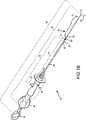
図1に示す縫合装置(10)は、一方の端部に中空穿刺チップ(22)を備え基端に回転および前進/後退可能なハンドル(24)を備えた長尺状ニードルアセンブリ(20)を具備する。ニードルアセンブリ(20)は、さらに、ボビン部(26)を備える。ボビン部(26)の周囲には、予備形成結節を備えた一本の縫合材を配置することができる(図1Aには示していない)。これに関して、縫合装置(10)はまた、ニードルアセンブリ(20)のボビン(26)に隣接して配置可能であるプッシャー端部(32)を備え、さらに基端に選択的に前進/後退可能なハンドル(34)を備えた結節配置アセンブリ(30)を有する。
【0024】
縫合装置(10)は、また、結節配置アセンブリ(30)のプッシャー端部(32)とニードルアセンブリ(20)のボビン(26)に隣接して配置可能である、縫合糸切断面を備えた先端(42)を具備する縫合糸切断アセンブリ(40)を含む。縫合糸切断アセンブリ(40)は、さらに、基端に前進/後退可能なハンドル(44)を含む。また、縫合装置(10)は、ニードルアセンブリ(20)の中空穿刺チップ(22)から選択的に前進/後退するように先端に配置されたフープ部材(52)を備え、さらに、基端に提供された選択的前進/後退および回転可能なハンドル(54)を備えた縫合把持アセンブリ(50)を含む。最後に、縫合装置(10)は、縫合装置(10)の操作に使用する基端側の主ハンドル部(60)を含む。
【0025】
裏面斜視図から分かるように、把持アセンブリ(50)、ニードルアセンブリ(20)、結節配置アセンブリ(30)および縫合糸切断アセンブリ(40)は、互いに対して、独立して選択的に前進/後退および/または回転を行なうために、同心同軸状に配置されている。さらに、把持アセンブリ(50)およびニードルアセンブリ(20)は、所望であれば、同時回転を可能にする所定の摩擦界面を設けて配置することができる。同様に、ニードルアセンブリ(20)の基端側ハンドル(24)および主ハンドル(60)は、所望であれば、同時回転をし易くする所定の摩擦界面を設けて配置することができる。これに関して、次ぎに、それぞれ図1Aの縫合装置(10)の先端側および基端側の断面を図示する図2Aおよび図3Aを参照する。
【0026】
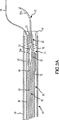
特に、把持アセンブリ(50)に関して、図3Aは、ニードルアセンブリ(20)内に後退した非展開位置のフープ部材(52)を例示する。これに関して、フープ部材(52)は、開口(52a)を備えたフープを画定する形状に形成されたワイヤ様材料から形成され得ることに注目すべきである。次ぎに記載するように、フープ部材(52)をニードルアセンブリ(20)の穿刺端部(22)の先端側チップを通って前進させると、フープ部材(52)は、縫合過程において縫合材付近に選択的に配置され、縫合材を把持するために、自動的に開放状態に跳ね拡がって所定の形状(例えば、ダイアモンド形状)になる。図5において、フープ部材(52)の先端が、好ましくは、約15°以上の内角θを画定することに留意されたい。フープ部材(52)を画定するのに用いるワイヤ様材料の端部は、首部分(56)に形成された2つの受容溝によって首部分(56)と相互連結することがでる。首部分(56)は、次に、ほぼ縫合装置(10)の長さにわたって延びて、図2Aに示すように、基端側ハンドル(54)に隣接するロッド部材(58)と固定的に相互連結され得る。後者に関連して、図2Aにおいて、ハンドル(54)がニードルアセンブリ(20)のハンドル(24)を通って回転可能かつ摺動可能に係合するように配置されていることが理解できる。このような目的のため、開口(24b)がハンドル(24)内部に形成されている。
【0027】
ニードルアセンブリ(20)に関して、図3Aは、穿刺チップ(22)が別個の端部部分(22a)とボビン部(26)の開口端部内に固定された中間部材(23)とにより画定されることを示している。これに関して、様々な異なる端部部分の形状を用い得ることに注目すべきである。特に、図4は、幾つかの異なる穿刺チップ端部部分(22a〜22e)を示す。各端部部分(22a〜22e)は、様々な適用において特有の機能的な利点を提供することができる。例えば、端部部分(22a)は、平坦な同一平面上で縫合するのに使用でき、端部部分(22b)は、隆起または起伏した同一平面を縫合するのに使用できる。端部部分(22c)は、浅い縫い合わせに使用できる。端部部分(22d)は、より筋肉質の頑強な組織を縫合するらせん形であり、端部部分(22e)は、汎用目的の縫合に使用することができる。
【0028】
次ぎに、図2Aと図3Aに戻って、ニードルアセンブリ(20)のボビン(26)が、基端側ハンドル(24)と相互連結するために、ほぼ縫合装置(10)の長さにわたって延びる駆動管(28)と相互連結し得ることに注目すべきである。これに関して、図2に最も良好に示されるように、把持アセンブリ(50)のロッド部材(58)は、ニードルアセンブリ(20)の駆動管(28)内に摺動可能に受容される。次に、駆動管(28)の基端は、基端側ハンドル(24)の内部シャフト部(24a)と相互連結する。シャフト部分(24a)は、縫合装置(10)の主ハンドル(60)の開口(62)内に摺動可能に受容され得る寸法にされている。
【0029】
次ぎに、図3Aを再度参照し、ニードルアセンブリ(20)のボビン(26)の回りに巻き付けた一本の縫合材(70)を示す。縫合材(70)の第一端部(72)は、結節配置アセンブリ(30)のプッシャー端部(32)と相互に連結し、一方、縫合材(70)の第二自由端部(74)は、結節配置アセンブリ(30)のプッシャー端部(32)から離れて延びる位置に示される。縫合材(70)の巻回部分(76)は、予備形成結節(例えば、Roeder結節)を含む。縫合装置(10)の使用に関連して、縫合材(70)の第二端部(74)は、ニードルアセンブリ(20)の中空穿刺チップ(22)を通過した把持アセンブリ(50)のフープ部材(52)によって把持され、引っ張られ得ることに注目すべきである。さらに、縫合装置(10)の使用中、結節配置アセンブリ(30)を使用して、予備形成結節部分(74)を選択的に配置することができる。すなわち、結節配置アセンブリ(30)のハンドル(34)を選択的に前進させ、かつ/またはニードル配置アセンブリ(20)のハンドル(24)を選択的に後退させて、縫合材(70)の予備形成結節をニードルアセンブリ(20)の先端を越えて「落とす」ことができる。
【0030】
さらに、結節配置アセンブリ(30)に関して、図3Aは、プッシャー端部(32)が、長尺状管部材(36)の端部内に適合する別個の部品(35)により画定され得ることを示している。次に、長尺状管部材(36)は、基端側ハンドル(34)と相互連結するため、ほぼ縫合装置(10)の長さにわたって延びる。これに関して、図2Aに最も良好に示されるように、ニードルアセンブリ(20)の駆動管(28)は、結節配置アセンブリ(30)の管部材(36)内に摺動可能に受容され得る。次に、管部材(36)の基端は、基端側ハンドル(34)の内部シャフト部分(34a)と相互に連結することができる。シャフト部分(34a)は、縫合装置(10)の主ハンドル(60)の円筒状開口(64)内に摺動可能に受容され得る寸法を有する。
【0031】
縫合糸切断アセンブリ(40)に関して、図3Aは、別の部材が先端側切断端部(42)を画定し得ることを例示する。次に、先端部材(42)は、ほぼ縫合装置(10)の長さに延びる長尺状管部材(46)の開口端部内に堅固に受容され得る。図2Aに最も良好に示されるように、結節配置アセンブリ(30)の管部材(36)は、縫合糸切断アセンブリ(40)の管部材(46)内に摺動可能に受容され得る。管部材(46)の基端は、基端側ハンドル(44)の内部シャフト部分(44a)と相互連結することができる。シャフト部分(44a)は、結節配置アセンブリ(30)の基端側ハンドル(34)の円筒状開口(34b)内に摺動可能に受容され得る寸法を有する。
【0032】
次ぎに、図1B、図2Bおよび図3Bを参照し、縫合装置(10)の代替実施形態を例示する。言うまでもなく、図1B、図2Bおよび図3Bに示す実施形態は、図1A、図2Aおよび図3Aの実施形態とかなり類似している。このように、共通の参照番号を用い、共通して用いた参照番号に関しては、上記に提供した説明が適用できる。しかし、図1B、図2Bおよび図3Bの実施形態における幾つかのさらに別の特徴に注目すべきである。
【0033】
特に、図3Bにより最も良く示されるように、例示の縫合装置(10)は、さらに、案内アセンブリ(80)と縫合糸支持アセンブリ(90)を具備する。案内アセンブリ(80)は、ニードルアセンブリ(20)の案内装置として機能し、縫合糸支持アセンブリ(90)の支持も行う。案内アセンブリ(80)は、内部部材(82)と、該内部部材(82)と相互連結した外側部材(84)とを具備する。外側部材(84)は、縫合装置(10)の先端側領域からその基端へ延び、図2Bに示すように、基端で主ハンドル(60)と相互連結する。
【0034】
縫合糸支持アセンブリ(90)は、縫合材(70)を支持するもので、スプール部材(92)と相互連結部材(94)を具備する。支持アセンブリ(90)は、案内アセンブリ(80)の内部部材(82)の端部を超えて摺動可能に同心的な配置ができる寸法を有する。相互連結部材(94)には、結節配置アセンブリ(30)のプッシャー端部(32)とスナップ嵌めによる相互連結するように適合された基端(94a)が備えられている。関連して、スプール部材(92)には、案内アセンブリ(80)の外側部材(84)の先端とスナップ嵌めによる相互連結に適合させた基端(92a)が備えられている。図3Bに示すように、縫合材(70)の基端(72)は、相互連結部材(94)に繋留されており、予備形成結節を備えた巻回部分(76)は、最初はスプール部材(92)の周りに配置されている。そのように、プッシャーチップ(32)の前進により、相互連結部材(94)は、スプール部材(92)に対して前進して巻回部分(76)と係合することになり、それによって、所望のように、予備形成結節をスプール部材(92)端部の先に「落とす」ことになる。
【0035】
案内アセンブリ(80)および支持アセンブリ(90)を備えることにより、複数の縫合操作および縫合装置(10)の再使用が容易になることが理解できる。すなわち、所与の組織の縫合/結節配置の操作後、縫合装置(10)を患者の体内から除去することができ、新しい支持アセンブリ(90)を次ぎの使用のため、容易に設置することができる。もちろん、このような配置は、使い捨て品として縫合糸支持アセンブリ(90)を提供することができる。その場合、スプール部材(92)および相互連結部材(94)は、プラスチックから構成され、別の流通および保管のため、縫合材(70)とともに組み立てられて梱包される。
【0036】
次ぎに、図1Bと図2Bを参照して、本実施形態のさらに別の特徴に言及する。特に、把持アセンブリ(50)の基端側ハンドル(54)には、ニードルアセンブリ(20)の基端側ハンドル(24)の基端側面と当接することによって、把持アセンブリ(50)のフープ部材(52)の不都合な先端側前進を制限するように配置された一つ以上のフィンガー部材(54a)が備えられている。このような前進が所望される場合には、フィンガー部材(54a)を基端側ハンドル(54)の中心軸線方向に向かって圧搾され、それによってフィンガー部材(54)が基端側ハンドル(24)の開口(24b)内へ摺動可能に受容されるようになる。
【0037】
さらに、図1Bおよび図2Bにより例示されるように、結節配置アセンブリ(30)には、また、改変基端側ハンドル(34)が備えられている。より詳細には、基端側ハンドル(34)は、主ハンドル(60)に形成された開口(66)内に選択的かつ摺動可能に前進/後退するように配置された片持ち式スライドタブ(34c)を含む。さらに、スライドタブ(34c)の基端は、主ハンドル(60)に形成された凹部(68)内への受容を互いに錠止する選択的な錠止係合を行なうために拡張されている。このような錠止係合は、縫合装置(10)の使用中に結節配置アセンブリ(30)の意図しない前進を制限する。前進が所望される場合には、使用者は、ハンドル(34)および/またはスライドタブ(34c)上の先端側に提供された主フランジ(34d)を押すだけでよい。その場合、スライドタブ(34c)の拡張基端と対向する傾斜部(示していない)および開口(66)が、片持ち式スライドタブ(34c)を外側に少し旋回させ、先端側に前進するように促す。
【0038】
言及したように、両実施形態の縫合装置(10)は、特に、内視鏡適用に適している。これに関して、把持アセンブリ(50)、ニードルアセンブリ(20)、結節配置アセンブリ(30)および縫合糸切断アセンブリ(40)は、口、肛門および他の内視鏡的接触位置/管を通過するように設計された内視鏡を介して通過できるように可撓性に構成されたものであることは明らかであろう。
【0039】
さらに、一般的な内視鏡用途には、駆動管(28)および管部材(36),(46)、の長さ、並びに部材(56),(58)が結合した長さは、好ましくは、少なくとも約179cm(70”)にすべきであり(腹腔鏡用途には少なくとも約13cm(5”))、縫合糸切断アセンブリ(40)の管部材(46)の外径は、好ましくは約14.3mm(0.562”)を超えるべきではない。相応じて、管部材(36)、駆動管(28)およびロッド部材(58)の外径は、段階的に減少するように設定すべきである。これに関して、把持アセンブリ(50)のロッド部材(58)の外径は、好ましくは、約0.38mm〜1.22mm(0.015”〜0.048”)にすべきだが、ニードルアセンブリ(20)の管部材(28)の外径は、好ましくは、約0.5mm〜1.57mm(0.020”〜0.062”)にすべきであると決定された。さらに、フープ部材(52)と穿刺チップ(22)に関して所望の制御を提供するため、把持アセンブリ(50)とニードルアセンブリ(20)が、それぞれの長さにそって、それぞれ約0.0023J(0.02in lb)以上のねじり強度と約1.38kPa(0.2in lb)以上の座屈強度をもつことが好ましい。
【0040】
このようなサイジングと強度特性に適応させるため、把持アセンブリ(50)のロッド部材(58)、フープ部材(52)と首(56)、ニードルアセンブリ(20)の駆動管(28)と穿刺チップ(22)、プッシャー管(32)および管部材(46)は、ニッケル、チタニウムおよびニッケル・チタニウム合金を含み得ることが見い出されている。このような構成部材に用いられる他の材料は、ばね鋼、ステンレス鋼、強化プラスチック被覆(つまり、カテーテル管)、網目状ワイヤ管が含まれると考えられる。
【0041】
次ぎに、図6A〜6Cを参照して、側面ポート(104)から挿入して、管状部材(102)内に配置した縫合装置(10)を設けた内視鏡装置(100)を例示する。言うまでもなく、内視鏡装置(100)は、患者体内の目的の組織領域に選択的に接近し易くするため、内視鏡装置(100)の先端(108)を外部から操縦する制御装置(106)を具備することができる。
【0042】
これに関して、内視鏡装置(100)は、内部を通過する多数の管を備え、それらの管は先端(108)において別個のポートを備える。例示として、次ぎに図6Bを参照すると、ポート(110a),(110b)と(110c)および(110e)は、それらの内部に画像化装置、光源、および灌注装置を配置するために備えられ得る。ポート(110d)は、該ポートを通過する縫合装置(10)などの器具を選択的に通過させるために備えられる。組織部位に接近するため、内視鏡装置(100)を通して縫合装置(10)を配置するとき、縫合装置(10)は、先端(108)に位置した画像化装置の視野内で前進/後退させることができる。これに関して、図6Cは、リアルタイムで使用者の表示器(200)と相互連結した画像化装置を備えた内視鏡装置(100)で用いる場合、縫合装置(100)がどのように見えるかを例示する。例示のように、ニードルアセンブリ(20)の穿刺チップ(22)は、先端(108)に配置された画像化装置により画定された視野内に突出するので、縫合操作を容易に観察/制御することができる。
【0043】
次ぎに、図7A〜図7Tを参照して、内視鏡に適用した例証の2点スイッチ式縫合操作方法を説明する。言うまでもなく、このような操作の前に、内視鏡装置(100)は、目的の組織領域の近くに先端(108)を配置して、患者体内に挿入されている。さらに、内視鏡装置(10)を用いて、組織部位に対して、例えば、外科的切開を行うために内視鏡装置(100)のポート(108d)を介して外科器具を操作し、ついで除去する外科的操作などの医療操作を行ていてもよい。
【0044】
図7Aに例示するように、縫合装置(10)を内視鏡装置(100)から前進させてあるので、ニードルアセンブリ(20)の穿刺チップ(22)が外科的切開(300)に隣接する内視鏡装置(100)の先端(108)から突出しているのを認めることができる。例示の実施形態において、縫合材(70)の自由端部(74)が把持アセンブリ(50)のフープ部材(52)内で把持され、中空穿刺チップ(22)の端部内に引き込まれている。このような把持は、内視鏡装置(100)内へ縫合装置(10)を挿入する前に、完了するのが好都合であり得る。切開(300)に対して所望の位置へ穿刺チップ(22)を、例えば、内視鏡制御器(106)を操作して前進させる際に、穿刺チップ(22)が回転して切開(300)の組織と接触するように、ニードルアセンブリハンドル(24)を回転させることができる。
【0045】
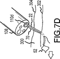
その後、図7Bに示されるように、ニードルアセンブリハンドル(24)を用いて、穿刺チップ(22)を組織内へ所望距離だけ前進させることができる。次ぎに、図7Cに示すように、ニードルアセンブリハンドル(24)を回転させて、穿刺チップ(22)を回転させて組織から外へ出し、切開部位(300)で部分的に持ち上げ動作を生じさせることができる。例示のように、穿刺チップ(22)の前進/回転を制御することにより、縫合材(70)が外科的切開(300)の第一側面(302)上の組織を介して引っ張られる。ここで、図7Dに示すように、次ぎに、ハンドル(54)を用いて、フープ部材(52)を穿刺チップ(22)の中空端部から外へ前進させ、次いで、フープ部材から縫合材(70)の自由端部(74)を開放または放出するように、ハンドルを回転させることができる。その後、図7Eに示すように、ハンドル(54)を操作して、フープ部材(52)を穿刺チップ(22)内に後退させて戻すことができ、ハンドル(24)を用いて、切開(300)の第一側面(302)上で組織から外へ穿刺チップ(22)を引き戻すことができる。
【0046】
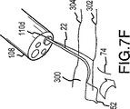
次ぎに、図7Fに示すように、把持アセンブリ(50)のハンドル(54)を前進させて、穿刺チップ(22)の端部から外へフープ部材(54)を再度展開させることができる。さらに、図7Fに示すように、フープ部材(52)を回転および前進させて、フープ部材(52)を介して縫合材(70)の自由端部(74)を選択的に配置するようにできる。このように配置すると、図7Gに示すように、フープ部材(52)を再度、中空穿刺チップ(22)の端部内へ後退させることにより、縫合材(70)の自由端部(74)を把持することができる。
【0047】
次ぎに、図7Hに示すように、縫合装置(10)を配置し、ニードルアセンブリハンドル(54)を介して穿刺チップ(22)を回転させて、開口(300)の第二側面(304)の組織と接触させることができる。次ぎに、図7Iに示すように、穿刺チップ(22)を組織に所望の距離だけ前進させ、図7Jに例示するように、穿刺チップ(22)を回転させて切開(300)から第二側面(304)上の組織を通って退出させることができる。図7Kに示すように、フープ部材(52)を再度穿刺チップ(22)から外へ前進させて、縫合材(70)の端部部分(74)を解放することができる。次ぎに、図7Lに示すように、フープ部材(52)を穿刺チップ(22)の端部内に後退させ、縫合材の端部部分(74)が開口(300)から突き出たままにすることができる。もう一度、図7Mに示すように、次ぎに、穿刺チップ(22)を組織から引き抜いた後、穿刺チップ(22)の端部から外へフープ部材(52)を前進させることができる。次ぎに、図7Nに示すように、縫合材の突出端部(74)付近に配置するために、フープ部材(52)を回転させる。このような配置が行われたら、次ぎに、図7Oに示すように、フープ構成要素(52)を先端側チップ(22)の端部内に後退させ、縫合材(70)の端部部分(74)を把持し得る。
【0048】
その後、図7Pに示すように、開口部位(300)の縫い目を引き締めるように穿刺チップ(22)および/または縫合装置(10)を後退または引き戻し得る。図7Qに示すように、縫合材(70)に張力をかけたまま、結節配置アセンブリハンドル(34)を穿刺チップ(22)に対して前進させて、穿刺チップ(22)の端部に対して予備形成結節(76)を押しつけて該穿刺チップ端部から外すことができる。図7Rに例示するように、次ぎに、結節配置アセンブリ(30)の先端(32)をさらに前進させて、切開部位(300)の近傍に予備形成結節部分(76)を配置することができる。次ぎに、図7Sに例示するように、結節配置アセンブリ(34)の先端(32)を再度後退させ、縫合装置(10)および/またはニードルアセンブリ(20)を操作して、切開(300)で結節部分(76)をさらに引き締めることができる。最後に、図7Tに示すように、ニードルアセンブリ(24)を回転させ、かつ/または縫合材(70)を縫合糸切断アセンブリ(40)の先端(42)面と接触させるように縫合装置(10)を別の方法で操作して、それによって、縫合材(70)を切断することができる。
【0049】
その後、縫合装置(10)を内視鏡装置(100)の先端(108)から引き戻して、縫合操作を完了することができる。これに代わって、別の縫合糸支持アセンブリ(90)を取り付け、その後、縫合装置(10)を内視鏡装置(100)内に再挿入し、別の縫合操作を完了することができる。このような操作は、所望の縫合結果を得るため、医療従事者が望み得る回数繰り返すことができる。
【0050】
上記に述べた実施形態および方法は、例示のためだけであり、本発明の範囲を限定しようとするものではない。記載の装置および方法の数多くの変更、修正および拡張は、当業者にとって明らかになろうし、添付の特許請求の範囲により画定されるように、本発明の範囲内とするものである。
【図面の簡単な説明】
【図1A】 本発明を含む装置の代替実施形態の等角図。
【図1B】 本発明を含む装置の代替実施形態の等角図。
【図2A】 図1Aの実施形態の基端部分の断面図。
【図2B】 図1Bの実施形態の基端部分の断面図。
【図3A】 図1Aの実施形態の先端部分の断面図。
【図3B】 図1Bの実施形態の先端部分の断面図。
【図4】 開示実施形態の使用に適した5つの代替穿刺チップを例示する図。
【図5A】 それぞれ前進および後退位置における図1B、図2Bおよび図3Bの実施形態の把持アセンブリの等角図。
【図5B】 それぞれ前進および後退位置における図1B、図2Bおよび図3Bの実施形態の把持アセンブリの等角図。
【図6A】 図1Aの実施形態を使用した内視鏡システム適用を示す図。
【図6B】 図6Aのシステムの使用に適した内視鏡の端面図。
【図6C】 図6Aのシステムで使用するのに適した表示装置を例示する図。
【図7A】 図6A〜6Cのシステムで図1Bの実施形態を使用する場合の工程を示す図。
【図7B】 図6A〜6Cのシステムで図1Bの実施形態を使用する場合の工程を示す図。
【図7C】 図6A〜6Cのシステムで図1Bの実施形態を使用する場合の工程を示す図。
【図7D】 図6A〜6Cのシステムで図1Bの実施形態を使用する場合の工程を示す図。
【図7E】 図6A〜6Cのシステムで図1Bの実施形態を使用する場合の工程を示す図。
【図7F】 図6A〜6Cのシステムで図1Bの実施形態を使用する場合の工程を示す図。
【図7G】 図6A〜6Cのシステムで図1Bの実施形態を使用する場合の工程を示す図。
【図7H】 図6A〜6Cのシステムで図1Bの実施形態を使用する場合の工程を示す図。
【図7I】 図6A〜6Cのシステムで図1Bの実施形態を使用する場合の工程を示す図。
【図7J】 図6A〜6Cのシステムで図1Bの実施形態を使用する場合の工程を示す図。
【図7K】 図6A〜6Cのシステムで図1Bの実施形態を使用する場合の工程を示す図。
【図7L】 図6A〜6Cのシステムで図1Bの実施形態を使用する場合の工程を示す図。
【図7M】 図6A〜6Cのシステムで図1Bの実施形態を使用する場合の工程を示す図。
【図7N】 図6A〜6Cのシステムで図1Bの実施形態を使用する場合の工程を示す図。
【図7O】 図6A〜6Cのシステムで図1Bの実施形態を使用する場合の工程を示す図。
【図7P】 図6A〜6Cのシステムで図1Bの実施形態を使用する場合の工程を示す図。
【図7Q】 図6A〜6Cのシステムで図1Bの実施形態を使用する場合の工程を示す図。
【図7R】 図6A〜6Cのシステムで図1Bの実施形態を使用する場合の工程を示す図。
【図7S】 図6A〜6Cのシステムで図1Bの実施形態を使用する場合の工程を示す図。
【図7T】 図6A〜6Cのシステムで図1Bの実施形態を使用する場合の工程を示す図。[0001]
(Field of Invention)
The present invention relates to the field of minimally invasive internal surgery, and in particular to suturing within a patient by manipulating the device outside the patient's body. Dress Related to the position.
[0002]
(Background of the Invention)
Minimally invasive internal surgical procedures are increasing. Such procedures typically require insertion of a tubular member into the patient and access of various devices to the target tissue site via the tubular member.
[0003]
In the laparoscopic method, a plurality of tubular members, such as trocar needles, can be inserted through the offset incision and advanced close to the target tissue site. The tubular member used is relatively stiff and has a sufficient diameter to allow various types of devices such as gas expansion conduits, electrosurgical devices, imaging devices and suturing devices to pass easily. Needless to say, laparoscopic surgical methods include methods aimed at fundoplication, myomectomy, spleen removal, hernia suture and cholecystectomy.
[0004]
Endoscope operating methods usually provide a means for inserting a single tubular member through a body mouth and for accessing instruments through the tubular member to an internal tissue site, for example, from the mouth or anus to a body cavity organ To do. Given such an inlet and associated body tube, tubular members used in endoscopic applications will necessarily be resiliently configured and can be of considerable length. Such considerations pose particular problems in the design and development of endoscopic surgical devices and techniques. To date, endoscopic manipulation methods have been mainly limited to gastroesophageal (GERD) and biopsy applications. However, it is believed that new surgical devices and methods of operation can be developed that facilitate increased endoscopic applications involving ligation, proximity and suturing of stomach and colon tissue.
[0005]
Common to both laparoscopic and endoscopic surgical methods is the need to effectively suture the intended internal tissue site. Such suturing requires passing the suture material in and out of the tissue one or more times, most commonly multiple times, and then providing a knot near the suture tissue and tightening. Needless to say, the completion of the suturing operation method for laparoscopic and endoscopic applications is a difficult task and sometimes provides tedious work for surgical staff. For example, such a stitching method may involve difficult manipulation of an external device that causes the needle located therein to pass completely through the tissue at the surgical site to provide a stitched seam. Further, some methods may require time-consuming removal and reinsertion of the entire suturing device and its accessor tubing to provide a suture knot at the suture site.
[0006]
(Summary of Invention)
In view of the foregoing, the broad purpose of the present invention is to provide an internal stitch that can be used relatively easily and very efficiently. Combination Is to provide a position.
Another object of the present invention is to provide an internal suture so as to reduce the cost and complexity of the member.
[0007]
Yet another object of the present invention is to provide an internal suture so as to reduce the total time required to suture in a given operation.
Yet another object of the present invention is to provide an internal suture so that it can be adapted to a very wide variety of applications. Do That is.
[0008]
Yet another object of the present invention is to provide an internal stitch by imaging the entire stitching process substantially continuously.
One or more of the above objects and additional advantages include a needle member with a tip and a pre-tied knot (hereinafter “pre-tied knot”) located near the tip of the needle member. (E.g., a pre-formed nodule) (e.g., implemented in a suturing device having a suture with a loader knot. Needless to say, the needle member "threads" the suture through the tissue at the surgical site. Therefore, it has a sufficient length to allow external operation of the proximal end.
[0009]
In one aspect of the present invention, the apparatus further includes a first member disposed to allow selective relative movement between the first member and the needle member. With such relative movement, the first member can be arranged to engage the suture, thereby placing a preformed nodule beyond the tip of the needle member, for example, for subsequent tightening at the surgical site. To do. Thanks to this arrangement, the provision of a suture knot at the suture site can be achieved accurately and easily.
[0010]
The tip of the needle member can include a puncture tip. By way of example, such a puncture tip can take a linear or arcuate shape. Similarly, the needle member may be provided such that its proximal end provides a substantially simultaneous rotational movement of the piercing tip that passes through the corresponding arc. Needless to say, such simultaneous rotational movement facilitates the passing of the needle member's puncture tip into and out of the tissue at the surgical site as desired during the suturing operation, ie, suturing. In this regard, it is preferable to provide a needle member having a torsional strength of about 0.0023 J (0.02 in. Lb) or more and a buckling strength of about 1.38 kPa or more from the distal end to the proximal end of the needle member.
[0011]
In order to facilitate the use in an endoscope application, the needle member is elongated, About 0.25cm ( 0.10 inch ) Can have a maximum cross-sectional width or diameter. Further, for such applications, the elongate needle member may preferably include a resilient material that can bend and bend to some extent along its length. By way of example, the elongate needle member may comprise a material selected from nickel, titanium or nickel-titanium alloy, stainless steel, spring or surgical stainless steel or elastic plastic.
[0012]
The device of the present invention can further comprise a second member with a tip suitable for cutting the suture. At least one of the second member, the first member, and the needle member is arranged to allow selective relative movement therebetween. More particularly, the second member may be arranged to selectively advance / retract relative to each of the first member and the needle member. Such an arrangement, for example, facilitates selective placement of the second member in the forward position to cut the suture after the tissue is sutured and the preformed nodule is placed / tightened at a given surgical site. Like that.
[0013]
In another aspect of the present invention, there is provided a suturing device comprising a needle and a suturing material having one end anchored near the distal end of the suturing needle. Again, the device can be designed so that the needle can be manipulated externally to pass the suture through the tissue at the internal surgical site. The suturing device also includes a gripping member. The needle and gripping member are arranged such that selective relative movement between them is possible. With such selective relative movement, the grasping member can be placed beyond the tip of the needle, for example, to selectively grasp and / or release the suture after passing the suture through the tissue at the surgical site. .
[0014]
In connection with this aspect of the invention, the gripping member is disposed through at least a portion of the needle, eg, a hollow piercing tip at the tip of the needle, and gripped by selective relative movement between the hollow piercing tip and the gripping member. The member is adapted to nest over the hollow piercing tip. Further, the gripping member can include an elastic load portion (for example, the gripping member can be shaped to exhibit elastic load behavior). When the elastic load portion is disposed within the hollow puncture tip of the needle, the elastic load portion is folded into a non-deployed state, and when the elastic load portion is disposed beyond the tip of the needle, the elastic load portion is automatically restored to the expanded state. In one embodiment, the elastic loading portion of the gripping member is selectively placed near the end of the suture in the deployed state and ends through the interior in the undeployed state (eg, when retracted into the hollow puncture tip of the needle). A hoop-like shape that captures the part can be formed.
[0015]
In one configuration for carrying out various aspects of the invention, a suturing device is provided that includes a gripping member, a needle member, a knot placement member, and a suture cutting member. Each member extends in parallel from the distal end to the proximal end of the suturing device. For example, such members can be arranged concentrically. For example, the gripping member is disposed through the needle member, the needle member is disposed through the knot disposition member, and the knot disposition member extends through the suture cutting member. As a result, adjacent members of the members are arranged such that they can be selectively advanced, retracted, and rotated relative to each other by manipulating corresponding handles provided at their proximal ends. Can be done. Of course, in the use of the suturing device, another operation outside the patient's body to provide the desired suturing operation at the internal tissue site near the tip of the corresponding grasping member, needle, knot placement member, and suture cutting member. In order to do this, the proximal handles may be interconnected.
[0016]
As described above, suturing devices with one or more features are particularly well suited for system applications. In this regard, in yet another aspect of the present invention, a tubular member suitable for insertion into a patient's body, an image disposed through the tubular member to obtain an image within the image field of view of the distal end of the tubular member. There is provided a suturing system of the present invention comprising a comminuting device and a suturing device disposed via a tubular member accessory for suturing in the vicinity of the distal end of the tubular member. The suturing device comprises a suturing needle that can be selectively advanced / retracted within the image field of view of the imaging device.
[0017]
In connection with this aspect of the invention, the suturing device may comprise a suture with a pre-formed knot disposed near the suturing needle. The suturing device can further comprise a first outer member. The suture needle and the first outer member can be arranged to allow selective relative movement between the suture needle and the first outer member. Such selective relative motion causes the first outer to place the preformed nodule beyond the tip of the suture needle for selective advancement and tightening of the surgical site within the image field of view of the imaging device. The member can be placed.
[0018]
In order to facilitate observation of the stitching process in real time, a display device may be provided in the system to display the captured image. Needless to say, such a display device can be conveniently arranged so that when the user operates the suturing device, the user can simultaneously observe. With respect to the latter, the suturing device can further include additional features, as described herein above.
[0019]
In yet another aspect of the invention, one or more inventive methods of internal suturing are provided. In one aspect, the suturing method of the present invention provides an end of the suture material at the tip of the suturing needle. Part Provided to hold and advance a finite portion of the suturing needle through the patient's tissue site. In this case, the end of the suture is pulled through the patient tissue site by the suture needle. Thereafter, the end of the suture material can be selectively released by the tip of the suture needle, and the finite portion of the suture needle can be removed from the patient tissue site, thereby leaving the end portion of the suture material protruding from the tissue site. it can. As a result, the projecting end portion can be gripped next, and the preformed nodule portion of the suture material can be disposed near the gripping end portion. Of course, such a method eliminates the need to completely penetrate the tissue site to complete the suturing process. Rather, in the described method, the suture needle can be used one or more times to pull the end of the suture from the tissue site and the needle can be removed from the tissue site after each use.
[0020]
In connection with the method of the invention, holding the suture at the tip of the suture needle grips the end of the suture and places the grip end in a hollow portion (eg, a hollow puncture tip) containing the tip of the suture needle. This can be achieved by pulling in. The grip end portion can then be released by advancing the grip end portion out of the hollow portion of the needle.
[0021]
Further, in connection with the method of the present invention, the placement of the preformed nodule portion is accomplished by advancing the preformed nodule relative to the grasping end of the suture material to tighten the preformed nodule portion near the tissue site. can do. In connection with such an arrangement, the grasping end of the suture can be drawn into the hollow portion at the tip of the suturing needle. After tightening the nodule, the suture can be selectively cut, for example, by selectively contacting the cut surface.
[0022]
Further aspects and advantages of the present invention will become apparent upon further consideration of the following description.
(Detailed explanation)
FIGS. 1A, 2A, 3A and 1B, 2B and 2C illustrate two embodiments of a suturing device (10) particularly suited for endoscopic applications. Of course, numerous other embodiments can be constructed that include one or more aspects of the present invention, such as, for example, embodiments specifically directed to laparoscopic applications.
[0023]
The suturing device (10) shown in FIG. 1 includes a long needle assembly (20) having a hollow puncture tip (22) at one end and a handle (24) that can be rotated and advanced / retracted at a proximal end. It has. The needle assembly (20) further includes a bobbin portion (26). A single suture with a pre-formed knot can be placed around the bobbin portion (26) (not shown in FIG. 1A). In this regard, the suturing device (10) also includes a pusher end (32) that can be positioned adjacent to the bobbin (26) of the needle assembly (20), and can be selectively advanced / retracted to the proximal end. It has a knot placement assembly (30) with a handle (34).
[0024]
The suturing device (10) also includes a tip with a suture cutting surface that is positionable adjacent the pusher end (32) of the knot placement assembly (30) and the bobbin (26) of the needle assembly (20). A suture cutting assembly (40) comprising (42). The suture cutting assembly (40) further includes a handle (44) that can be advanced / retracted at the proximal end. The suturing device (10) also includes a hoop member (52) disposed at the distal end for selective advancement / retraction from the hollow puncture tip (22) of the needle assembly (20), and further provided at the proximal end. A suture grasping assembly (50) with a selectively advanced / retracted and rotatable handle (54). Finally, the suturing device (10) includes a proximal main handle portion (60) used for operation of the suturing device (10).
[0025]
As can be seen from the rear perspective view, the gripping assembly (50), needle assembly (20), knot placement assembly (30) and suture cutting assembly (40) are selectively advanced and retracted independently of each other. In order to perform rotation, they are arranged concentrically and coaxially. Further, the gripping assembly (50) and needle assembly (20) can be arranged with a predetermined friction interface that allows simultaneous rotation, if desired. Similarly, the proximal handle (24) and the main handle (60) of the needle assembly (20) can be arranged with a predetermined friction interface to facilitate simultaneous rotation, if desired. In this regard, reference is now made to FIGS. 2A and 3A illustrating the distal and proximal cross sections of the suturing device (10) of FIG. 1A, respectively.
[0026]
In particular, with respect to the gripping assembly (50), FIG. 3A illustrates the hoop member (52) in the undeployed position retracted into the needle assembly (20). In this regard, it should be noted that the hoop member (52) may be formed from a wire-like material formed into a shape that defines a hoop with an opening (52a). As described below, when the hoop member (52) is advanced through the distal tip of the puncture end (22) of the needle assembly (20), the hoop member (52) is brought into the vicinity of the suture during the suturing process. In order to selectively arrange and grasp the suture material, it automatically jumps to the open state and becomes a predetermined shape (for example, a diamond shape). Note in FIG. 5 that the tip of the hoop member (52) preferably defines an interior angle θ of about 15 ° or greater. The end of the wire-like material used to define the hoop member (52) can be interconnected with the neck portion (56) by two receiving grooves formed in the neck portion (56). The neck portion (56) then extends approximately the length of the suturing device (10) and is fixedly reciprocal with the rod member (58) adjacent to the proximal handle (54), as shown in FIG. 2A. Can be linked. In connection with the latter, it can be seen in FIG. 2A that the handle (54) is arranged to engage rotatably and slidably through the handle (24) of the needle assembly (20). For this purpose, an opening (24b) is formed in the handle (24).
[0027]
With respect to the needle assembly (20), FIG. 3A shows that the puncture tip (22) is defined by a separate end portion (22a) and an intermediate member (23) secured within the open end of the bobbin portion (26). Is shown. In this regard, it should be noted that a variety of different end portion shapes may be used. In particular, FIG. 4 shows several different piercing tip end portions (22a-22e). Each end portion (22a-22e) can provide unique functional advantages in various applications. For example, the end portion (22a) can be used to sew on a flat, coplanar surface and the end portion (22b) can be used to sew a raised or undulated coplanar surface. The end portion (22c) can be used for shallow stitching. The end portion (22d) is a helical shape that sutures more muscular, robust tissue, and the end portion (22e) can be used for general purpose suturing.
[0028]
Next, returning to FIGS. 2A and 3A, the bobbin (26) of the needle assembly (20) extends approximately the length of the suturing device (10) to interconnect with the proximal handle (24). It should be noted that it can be interconnected with tube (28). In this regard, as best shown in FIG. 2, the rod member (58) of the gripping assembly (50) is slidably received within the drive tube (28) of the needle assembly (20). Next, the proximal end of the drive tube (28) interconnects with the inner shaft portion (24a) of the proximal handle (24). The shaft portion (24a) is dimensioned to be slidably received within the opening (62) of the main handle (60) of the suturing device (10).
[0029]
Next, referring again to FIG. 3A, a single suture (70) wrapped around the bobbin (26) of the needle assembly (20) is shown. The first end (72) of the suture (70) interconnects with the pusher end (32) of the knot placement assembly (30), while the second free end (74) of the suture (70). Is shown in a position extending away from the pusher end (32) of the knot placement assembly (30). The wound portion (76) of the suture (70) includes a preformed knot (eg, a Roeder knot). In connection with the use of the suturing device (10), the second end (74) of the suture (70) is passed through the hollow piercing tip (22) of the needle assembly (20) and the hoop member of the grasping assembly (50). Note that it can be gripped and pulled by (52). Further, during use of the suturing device (10), the knot placement assembly (30) can be used to selectively position the preformed knot portion (74). That is, the handle (34) of the knot placement assembly (30) is selectively advanced and / or the handle (24) of the needle placement assembly (20) is selectively retracted to pre-form the suture (70). The knot can be “dropped” over the tip of the needle assembly (20).
[0030]
Further, with respect to the knot placement assembly (30), FIG. 3A shows that the pusher end (32) may be defined by a separate piece (35) that fits within the end of the elongate tube member (36). Yes. The elongate tube member (36) then extends approximately the length of the suturing device (10) to interconnect with the proximal handle (34). In this regard, as best shown in FIG. 2A, the drive tube (28) of the needle assembly (20) may be slidably received within the tube member (36) of the knot placement assembly (30). The proximal end of the tube member (36) can then be interconnected with the inner shaft portion (34a) of the proximal handle (34). The shaft portion (34a) has dimensions that can be slidably received within the cylindrical opening (64) of the main handle (60) of the suturing device (10).
[0031]
With respect to the suture cutting assembly (40), FIG. 3A illustrates that another member may define the distal cutting end (42). The tip member (42) can then be firmly received within the open end of the elongate tube member (46) extending approximately the length of the suturing device (10). As best shown in FIG. 2A, the tube member (36) of the knot placement assembly (30) may be slidably received within the tube member (46) of the suture cutting assembly (40). The proximal end of the tube member (46) can be interconnected with the inner shaft portion (44a) of the proximal handle (44). The shaft portion (44a) is sized to be slidably received within the cylindrical opening (34b) of the proximal handle (34) of the knot placement assembly (30).
[0032]
Next, with reference to FIGS. 1B, 2B and 3B, an alternative embodiment of the suturing device (10) is illustrated. Needless to say, the embodiment shown in FIGS. 1B, 2B and 3B is quite similar to the embodiment of FIGS. 1A, 2A and 3A. As described above, the common reference numbers are used, and the description provided above can be applied to the common reference numbers. However, some further features in the embodiment of FIGS. 1B, 2B and 3B should be noted.
[0033]
In particular, as best shown in FIG. 3B, the exemplary suturing device (10) further comprises a guide assembly (80) and a suture support assembly (90). The guide assembly (80) functions as a guide device for the needle assembly (20) and also supports the suture support assembly (90). The guide assembly (80) includes an inner member (82) and an outer member (84) interconnected with the inner member (82). The outer member (84) extends from the distal region of the suturing device (10) to its proximal end and interconnects with the main handle (60) at the proximal end, as shown in FIG. 2B.
[0034]
The suture support assembly (90) supports the suture material (70) and includes a spool member (92) and an interconnecting member (94). The support assembly (90) has dimensions that allow it to be slidably concentrically positioned beyond the end of the inner member (82) of the guide assembly (80). The interconnecting member (94) is provided with a proximal end (94a) adapted to interconnect with a pusher end (32) of the knot placement assembly (30) by a snap fit. Relatedly, the spool member (92) is provided with a proximal end (92a) adapted for interconnection with a distal end of the outer member (84) of the guide assembly (80) and a snap fit. As shown in FIG. 3B, the proximal end (72) of the suture (70) is anchored to the interconnecting member (94), and the wound portion (76) with the preformed knot is initially the spool member. (92) around. As such, advancement of the pusher tip (32) causes the interconnecting member (94) to advance relative to the spool member (92) to engage the winding portion (76), thereby providing the desired Thus, the preformed knot will be “dropped” beyond the end of the spool member (92).
[0035]
It can be seen that providing a guide assembly (80) and a support assembly (90) facilitates multiple suturing operations and reuse of the suturing device (10). That is, after a given tissue suturing / nodal placement operation, the suturing device (10) can be removed from the patient's body and a new support assembly (90) can be easily installed for subsequent use. it can. Of course, such an arrangement can provide the suture support assembly (90) as a disposable. In that case, spool member (92) and interconnecting member (94) are constructed from plastic and assembled and packaged with suture material (70) for further distribution and storage.
[0036]
Next, with reference to FIG. 1B and FIG. 2B, further features of this embodiment will be mentioned. In particular, the proximal handle (54) of the gripping assembly (50) abuts the proximal side surface of the proximal handle (24) of the needle assembly (20). You Thus, one or more finger members (54a) are provided that are arranged to limit the undesired distal advancement of the hoop member (52) of the gripping assembly (50). If such advancement is desired, the finger member (54a) is squeezed toward the central axis of the proximal handle (54), thereby causing the finger member (54) to squeeze the proximal handle (24). Into the opening (24b) of the device.
[0037]
Further, as illustrated by FIGS. 1B and 2B, the knot placement assembly (30) is also provided with a modified proximal handle (34). More particularly, the proximal handle (34) is a cantilevered slide tab that is selectively and slidably advanced / retracted within an opening (66) formed in the main handle (60). (34c). In addition, the proximal end of the slide tab (34c) has been extended to provide a selective locking engagement that locks the reception into a recess (68) formed in the main handle (60). Such locking engagement limits unintentional advancement of the knot placement assembly (30) during use of the suturing device (10). If advancement is desired, the user need only push the main flange (34d) provided on the distal side on the handle (34) and / or slide tab (34c). In that case, the inclined portion (not shown) and the opening (66) facing the extended proximal end of the slide tab (34c) slightly pivot the cantilevered slide tab (34c) outward and advance toward the distal end side. Prompt.
[0038]
As mentioned, the suturing device (10) of both embodiments is particularly suitable for endoscopic applications. In this regard, the grasping assembly (50), needle assembly (20), knot placement assembly (30) and suture cutting assembly (40) pass through the mouth, anus and other endoscopic contact locations / tubes. It will be apparent that it is configured to be flexible so that it can pass through the designed endoscope.
[0039]
Furthermore, for general endoscopic applications, the length of the drive tube (28) and the tube members (36), (46) and the combined length of the members (56), (58) are preferably At least about 179 cm (70 ") (at least about 13 cm (5") for laparoscopic applications) and the outer diameter of the tube member (46) of the suture cutting assembly (40) is preferably about 14 .3 mm (0.562 ") should not be exceeded. Correspondingly, the outer diameters of the tube member (36), drive tube (28) and rod member (58) should be set to decrease step by step. In this regard, the outer diameter of the rod member (58) of the gripping assembly (50) should preferably be about 0.38 mm to 1.22 mm (0.015 "to 0.048"), but the needle Outer diameter of tube member (28) of assembly (20) And preferably should be between about 0.5 mm and 1.57 mm (0.020 ″ to 0.062 ″). Further, the desired control over the hoop member (52) and puncture tip (22). To provide a torsional strength of about 0.0023 J (0.02 in lb) or more and about 1.38 kPa (0.2 in), respectively, along their lengths. It is preferable to have a buckling strength of lb) or higher.
[0040]
To accommodate such sizing and strength characteristics, the rod member (58) of the grasping assembly (50), the hoop member (52) and neck (56), the drive tube (28) of the needle assembly (20) and the puncture tip ( 22) It has been found that the pusher tube (32) and tube member (46) may comprise nickel, titanium and nickel-titanium alloy. Other materials used for such components are believed to include spring steel, stainless steel, reinforced plastic coatings (ie catheter tubes), and mesh wire tubes.
[0041]
Next, with reference to FIGS. 6A to 6C, an endoscope apparatus (100) provided with a suturing device (10) inserted through a side port (104) and disposed in a tubular member (102) is illustrated. Needless to say, the endoscope apparatus (100) is a control apparatus (106) that steers the distal end (108) of the endoscope apparatus (100) from the outside in order to facilitate selective access to a target tissue region in the patient. ).
[0042]
In this regard, the endoscopic device (100) includes a number of tubes passing therethrough, and the tubes include separate ports at the tip (108). By way of example, referring now to FIG. 6B, ports (110a), (110b) and (110c) and (110e) may be provided for placing an imaging device, light source, and irrigation device therein. . The port (110d) is provided for selectively passing instruments such as the suturing device (10) passing through the port. When placing the suturing device (10) through the endoscopic device (100) to access the tissue site, the suturing device (10) is advanced / retracted within the field of view of the imaging device located at the tip (108). be able to. In this regard, FIG. 6C illustrates how the suturing device (100) looks when used in an endoscopic device (100) with an imaging device interconnected with a user display (200) in real time. Illustrate. As illustrated, the puncture tip (22) of the needle assembly (20) protrudes into the field of view defined by the imaging device located at the tip (108) so that the suturing operation can be easily observed / controlled. Can do.
[0043]
Next, an illustrative two-point switch stitching method applied to an endoscope will be described with reference to FIGS. 7A to 7T. Needless to say, prior to such an operation, the endoscopic device (100) is inserted into the patient with the tip (108) positioned near the target tissue region. Furthermore, the endoscopic device (10) is used to manipulate a surgical instrument through a port (108d) of the endoscopic device (100), for example, to make a surgical incision on a tissue site, and then A medical operation such as a surgical operation for removal may be performed.
[0044]
As illustrated in FIG. 7A, the suturing device (10) has been advanced from the endoscopic device (100) so that the puncture tip (22) of the needle assembly (20) is adjacent to the surgical incision (300). It can be seen that it protrudes from the tip (108) of the endoscopic device (100). In the illustrated embodiment, the free end (74) of the suture (70) is grasped within the hoop member (52) of the grasping assembly (50) and retracted into the end of the hollow puncture tip (22). Such gripping may be conveniently completed prior to inserting the suturing device (10) into the endoscopic device (100). When the puncture tip (22) is advanced to a desired position with respect to the incision (300), for example, by operating the endoscope controller (106), the puncture tip (22) is rotated and the incision (300) is performed. The needle assembly handle (24) can be rotated to contact the tissue.
[0045]
Thereafter, as shown in FIG. 7B, the needle assembly handle (24) can be used to advance the puncture tip (22) by a desired distance into the tissue. Next, as shown in FIG. 7C, the needle assembly handle (24) is rotated to rotate the puncture tip (22) out of the tissue, causing a partial lifting action at the incision site (300). be able to. As illustrated, the suture (70) is pulled through the tissue on the first side (302) of the surgical incision (300) by controlling the advancement / rotation of the puncture tip (22). Here, as shown in FIG. 7D, the hoop member (52) is then advanced out of the hollow end of the puncture tip (22) using the handle (54), and then the suture material ( The handle can be rotated to open or release the free end (74) of 70). Thereafter, as shown in FIG. 7E, the handle (54) can be manipulated to retract the hoop member (52) back into the puncture tip (22) and use the handle (24) to make an incision (300 ) Can be pulled back out of the tissue on the first side (302).
[0046]
Next, as shown in FIG. 7F, the handle (54) of the gripping assembly (50) can be advanced to redeploy the hoop member (54) out of the end of the puncture tip (22). Further, as shown in FIG. 7F, the hoop member (52) can be rotated and advanced to selectively place the free end (74) of the suture (70) through the hoop member (52). . With this arrangement, the free end (74) of the suture (70) is gripped by retracting the hoop member (52) back into the end of the hollow puncture tip (22) as shown in FIG. 7G. can do.
[0047]
Next, as shown in FIG. 7H, the suturing device (10) is placed and the puncture tip (22) is rotated through the needle assembly handle (54) to create a second side (304) of the opening (300). Can be contacted with tissue. Next, as shown in FIG. 7I, the puncture tip (22) is advanced a desired distance into the tissue, and as shown in FIG. 7J, the puncture tip (22) is rotated to move the second side from the incision (300). (304) Exit through the organization above. As shown in FIG. 7K, the hoop member (52) can again be advanced out of the puncture tip (22) to release the end portion (74) of the suture (70). Next, as shown in FIG. 7L, the hoop member (52) may be retracted into the end of the puncture tip (22), leaving the end portion (74) of the suture protruding from the opening (300). it can. Again, as shown in FIG. 7M, the hoop member (52) can then be advanced out of the end of the puncture tip (22) after the puncture tip (22) has been withdrawn from the tissue. Next, as shown in FIG. 7N, the hoop member (52) is rotated for placement near the protruding end (74) of the suture. Once such an arrangement has been made, the hoop component (52) is then retracted into the end of the distal tip (22), as shown in FIG. ).
[0048]
Thereafter, as shown in FIG. 7P, the puncture tip (22) and / or the suturing device (10) may be retracted or pulled back to tighten the seam at the opening site (300). As shown in FIG. 7Q, with the suture (70) under tension, the nodule placement assembly handle (34) is advanced relative to the puncture tip (22) and against the end of the puncture tip (22). The preformed nodule (76) can be pressed away from the piercing tip end. As illustrated in FIG. 7R, the tip (32) of the knot placement assembly (30) can then be further advanced to place the preformed knot portion (76) near the incision site (300). Next, as illustrated in FIG. 7S, the tip (32) of the knot placement assembly (34) is retracted again and the suturing device (10) and / or the needle assembly (20) is manipulated to provide an incision (300). The knot portion (76) can be further tightened. Finally, as shown in FIG. 7T, the suturing device (10) rotates the needle assembly (24) and / or brings the suture (70) into contact with the distal (42) surface of the suture cutting assembly (40). ) Can be manipulated in other ways, thereby cutting the suture (70).
[0049]
Thereafter, the suturing device (10) can be pulled back from the tip (108) of the endoscope device (100) to complete the suturing operation. Alternatively, another suture support assembly (90) can be attached, after which the suturing device (10) can be reinserted into the endoscopic device (100) to complete another suturing operation. Such an operation can be repeated as many times as may be desired by a healthcare professional in order to obtain a desired suture result.
[0050]
The embodiments and methods described above are for illustrative purposes only and are not intended to limit the scope of the invention. Numerous variations, modifications and extensions of the described apparatus and method will be apparent to those skilled in the art and are intended to be within the scope of the invention as defined by the appended claims.
[Brief description of the drawings]
FIG. 1A is an isometric view of an alternate embodiment of an apparatus comprising the present invention.
FIG. 1B is an isometric view of an alternative embodiment of an apparatus including the present invention.
2A is a cross-sectional view of the proximal end portion of the embodiment of FIG. 1A.
2B is a cross-sectional view of the proximal end portion of the embodiment of FIG. 1B.
3A is a cross-sectional view of the tip portion of the embodiment of FIG. 1A.
3B is a cross-sectional view of the tip portion of the embodiment of FIG. 1B.
FIG. 4 illustrates five alternative piercing tips suitable for use with the disclosed embodiments.
5A is an isometric view of the gripping assembly of the embodiment of FIGS. 1B, 2B, and 3B in the forward and retracted positions, respectively. FIG.
5B is an isometric view of the gripping assembly of the embodiment of FIGS. 1B, 2B, and 3B in the forward and retracted positions, respectively.
FIG. 6A is a diagram showing application of an endoscope system using the embodiment of FIG. 1A.
6B is an end view of an endoscope suitable for use with the system of FIG. 6A.
6C illustrates a display device suitable for use with the system of FIG. 6A.
7A shows a process for using the embodiment of FIG. 1B in the system of FIGS. 6A-6C. FIG.
7B shows a process for using the embodiment of FIG. 1B in the system of FIGS. 6A-6C. FIG.
7C shows a process for using the embodiment of FIG. 1B in the system of FIGS. 6A-6C. FIG.
7D shows a process for using the embodiment of FIG. 1B in the system of FIGS. 6A-6C. FIG.
7E shows a process for using the embodiment of FIG. 1B in the system of FIGS. 6A-6C. FIG.
FIG. 7F shows a process for using the embodiment of FIG. 1B in the system of FIGS. 6A-6C.
7G illustrates a process for using the embodiment of FIG. 1B in the system of FIGS. 6A-6C.
FIG. 7H shows a process for using the embodiment of FIG. 1B in the system of FIGS. 6A-6C.
FIG. 7I shows a process for using the embodiment of FIG. 1B in the system of FIGS. 6A-6C.
FIG. 7J shows a process for using the embodiment of FIG. 1B in the system of FIGS. 6A-6C.
FIG. 7K illustrates a process for using the embodiment of FIG. 1B in the system of FIGS. 6A-6C.
7L illustrates a process for using the embodiment of FIG. 1B in the systems of FIGS. 6A-6C. FIG.
FIG. 7M shows a process for using the embodiment of FIG. 1B in the system of FIGS. 6A-6C.
FIG. 7N shows a process for using the embodiment of FIG. 1B in the system of FIGS. 6A-6C.
FIG. 7O illustrates a process for using the embodiment of FIG. 1B in the system of FIGS. 6A-6C.
7P illustrates a process for using the embodiment of FIG. 1B in the systems of FIGS. 6A-6C.
FIG. 7Q shows a process for using the embodiment of FIG. 1B in the system of FIGS. 6A-6C.
7R illustrates a process for using the embodiment of FIG. 1B in the system of FIGS. 6A-6C. FIG.
FIG. 7S shows a process for using the embodiment of FIG. 1B in the system of FIGS. 6A-6C.
FIG. 7T illustrates a process for using the embodiment of FIG. 1B in the system of FIGS. 6A-6C.
Claims (18)
初めにニードル(20)の先端部付近に同心円状に配置される予備形成結節(76)を有する縫合材(70)と、
ニードル(20)の先端部に隣接して配置され、かつ初めに予備形成結節(76)に隣接して配置されたプッシャー端部(32,94)を有する第一部材(30,90)と、
把持部材(50)とを備え、
前記第一部材(30,90)およびニードル(20)は、同第一部材と同ニードルとの間における選択的相対運動が可能となるように相互連結され、プッシャー端部(32,94)と前記予備形成結節(76)とは同プッシャー端部と同予備形成結節(76)との間における選択的相対運動が可能となるように配置され、
前記選択的相対運動により、第一部材のプッシャー端部(32,94)がニードル(20)の前記先端部を越えて前記予備形成結節(76)を配置するように前記予備形成結節(76)と係合可能であり、
前記ニードル(20)と前記把持部材(50)とは、前記ニードル(20)と前記把持部材との間において選択的相対運動が可能となるように相互連結され、前記選択的相対運動により前記縫合材(70)の端部を把持するために、前記把持部材(50)の先端が前記ニードル(20)の内部から前記ニードル(20)の先端を越えて配置可能である、縫合装置。A needle (20) with a tip;
A suture (70) having a preformed nodule (76) initially concentrically disposed near the tip of the needle (20);
A first member (30, 90) having a pusher end (32, 94) disposed adjacent to the tip of the needle (20) and initially disposed adjacent to the preformed knot (76) ;
A gripping member (50) ,
The first member (30, 90) and the needle (20) are interconnected to allow selective relative movement between the first member and the needle, and the pusher end (32, 94). The preformed knot (76) is arranged to allow selective relative movement between the pusher end and the preformed knot (76) ;
By the selective relative movement, the first pusher end portion of the member (32,94) crab Doru (20) the tip the preformed knot to place the preformed knot (76) beyond the (76 ) And can be engaged
The needle (20) and the gripping member (50) are interconnected so as to allow selective relative movement between the needle (20) and the gripping member, and the suturing is performed by the selective relative movement. A suturing device in which the tip of the gripping member (50) can be placed from the inside of the needle (20) beyond the tip of the needle (20) to grip the end of the material (70) .
前記ニードル(20)の前記先端内に選択的に配置されると非展開状態に収縮し、前記ニードル(20)の前記先端を越えて配置されると自動的に展開状態に跳ね拡がる弾性負荷部を有する先端を具備し、前記弾性負荷部は、前記展開状態では、前記縫合材(70)の端部付近に選択的に配置され、かつ前記非展開状態では、前記端部を捕捉するためにフープ様形状(52)になっている、請求項1に記載の縫合装置。Comprising said gripping member (50), said gripping member (50) being selectively moved relative to a preformed nodule (76) and via said preformed nodule (76) the end of said suture material ( 70); Arranged to selectively grip and hold the part, the gripping member (50)
An elastic load portion that contracts in a non-deployed state when selectively disposed within the tip of the needle (20), and automatically jumps and expands into a deployed state when disposed beyond the tip of the needle (20). comprising a tip having a, the elastic load unit, wherein in the expanded state, wherein the selectively placed in the vicinity of the end portion of the suture (70), and wherein in the non-deployed state, to capture the pre-Symbol ends The suturing device according to claim 1, wherein the suturing device has a hoop-like shape (52).
前記案内アセンブリ(80)に対して摺動可能かつ同心状に配置される大きさに形成された縫合糸支持アセンブリ(90)とを更に備え、前記縫合糸支持アセンブリ(90)は相互連結部材(94)を含み、前記相互連結部材(94)は前記プッシャー端部(32)に対して相互接続するように適合された基端(94a)を含み、前記縫合材(70)の基端は前記相互連結部材(94)に繋留されている、請求項1に記載の装置。 A suture support assembly (90) sized to be slidable and concentrically disposed with respect to the guide assembly (80), the suture support assembly (90) being an interconnecting member (90); 94), the interconnecting member (94) includes a proximal end (94a) adapted to interconnect with the pusher end (32), and the proximal end of the suture (70) is The apparatus of claim 1, wherein the apparatus is anchored to the interconnecting member (94).
Applications Claiming Priority (3)
| Application Number | Priority Date | Filing Date | Title |
|---|---|---|---|
| US09/662,936 | 2000-09-15 | ||
| US09/662,936 US6554845B1 (en) | 2000-09-15 | 2000-09-15 | Suturing apparatus and method |
| PCT/US2001/025295 WO2002022026A1 (en) | 2000-09-15 | 2001-08-13 | Improved suturing apparatus and method |
Publications (3)
| Publication Number | Publication Date |
|---|---|
| JP2004508128A JP2004508128A (en) | 2004-03-18 |
| JP2004508128A5 JP2004508128A5 (en) | 2008-09-25 |
| JP4908722B2 true JP4908722B2 (en) | 2012-04-04 |
Family
ID=24659830
Family Applications (1)
| Application Number | Title | Priority Date | Filing Date |
|---|---|---|---|
| JP2002526283A Expired - Fee Related JP4908722B2 (en) | 2000-09-15 | 2001-08-13 | Improved suturing device |
Country Status (5)
| Country | Link |
|---|---|
| US (1) | US6554845B1 (en) |
| EP (1) | EP1317212B1 (en) |
| JP (1) | JP4908722B2 (en) |
| AU (1) | AU2001284858A1 (en) |
| WO (1) | WO2002022026A1 (en) |
Cited By (1)
| Publication number | Priority date | Publication date | Assignee | Title |
|---|---|---|---|---|
| KR20180119983A (en) * | 2017-04-26 | 2018-11-05 | 전남대학교산학협력단 | Medical Ligation Tool using Concentric Tubular Continuum Mechanism |
Families Citing this family (164)
| Publication number | Priority date | Publication date | Assignee | Title |
|---|---|---|---|---|
| US7618426B2 (en) | 2002-12-11 | 2009-11-17 | Usgi Medical, Inc. | Apparatus and methods for forming gastrointestinal tissue approximations |
| US7416554B2 (en) | 2002-12-11 | 2008-08-26 | Usgi Medical Inc | Apparatus and methods for forming and securing gastrointestinal tissue folds |
| US7744613B2 (en) | 1999-06-25 | 2010-06-29 | Usgi Medical, Inc. | Apparatus and methods for forming and securing gastrointestinal tissue folds |
| US7637905B2 (en) | 2003-01-15 | 2009-12-29 | Usgi Medical, Inc. | Endoluminal tool deployment system |
| US7887551B2 (en) | 1999-12-02 | 2011-02-15 | Smith & Nephew, Inc. | Soft tissue attachment and repair |
| US7220266B2 (en) | 2000-05-19 | 2007-05-22 | C. R. Bard, Inc. | Tissue capturing and suturing device and method |
| WO2003096885A2 (en) * | 2002-05-17 | 2003-11-27 | Onux Medical, Inc. | Surgical suturing instrument and method of use |
| US7942898B2 (en) | 2002-12-11 | 2011-05-17 | Usgi Medical, Inc. | Delivery systems and methods for gastric reduction |
| US7942884B2 (en) | 2002-12-11 | 2011-05-17 | Usgi Medical, Inc. | Methods for reduction of a gastric lumen |
| US20040127915A1 (en) * | 2002-12-30 | 2004-07-01 | Fleenor Richard P. | Suture hoop system |
| WO2004103189A1 (en) | 2003-05-16 | 2004-12-02 | C.R. Bard, Inc. | Single intubation, multi-stitch endoscopic suturing system |
| US8216252B2 (en) | 2004-05-07 | 2012-07-10 | Usgi Medical, Inc. | Tissue manipulation and securement system |
| JP4358589B2 (en) * | 2003-10-08 | 2009-11-04 | オリンパス株式会社 | Medical treatment tool |
| US7361180B2 (en) | 2004-05-07 | 2008-04-22 | Usgi Medical, Inc. | Apparatus for manipulating and securing tissue |
| US7347863B2 (en) | 2004-05-07 | 2008-03-25 | Usgi Medical, Inc. | Apparatus and methods for manipulating and securing tissue |
| US20050251189A1 (en) | 2004-05-07 | 2005-11-10 | Usgi Medical Inc. | Multi-position tissue manipulation assembly |
| JP4538247B2 (en) * | 2004-02-10 | 2010-09-08 | Hoya株式会社 | Endoscopic tissue collection puncture needle device |
| US7703459B2 (en) | 2004-03-09 | 2010-04-27 | Usgi Medical, Inc. | Apparatus and methods for mapping out endoluminal gastrointestinal surgery |
| US8257394B2 (en) | 2004-05-07 | 2012-09-04 | Usgi Medical, Inc. | Apparatus and methods for positioning and securing anchors |
| US8444657B2 (en) | 2004-05-07 | 2013-05-21 | Usgi Medical, Inc. | Apparatus and methods for rapid deployment of tissue anchors |
| US7520884B2 (en) * | 2004-05-07 | 2009-04-21 | Usgi Medical Inc. | Methods for performing gastroplasty |
| US7736374B2 (en) | 2004-05-07 | 2010-06-15 | Usgi Medical, Inc. | Tissue manipulation and securement system |
| US7918869B2 (en) * | 2004-05-07 | 2011-04-05 | Usgi Medical, Inc. | Methods and apparatus for performing endoluminal gastroplasty |
| US7931661B2 (en) * | 2004-06-14 | 2011-04-26 | Usgi Medical, Inc. | Apparatus and methods for performing transluminal gastrointestinal procedures |
| US8128640B2 (en) * | 2005-02-07 | 2012-03-06 | Ivy Sports Medicine LLC | System and method for all-inside suture fixation for implant attachment and soft tissue repair |
| JP5030797B2 (en) * | 2005-02-07 | 2012-09-19 | アイビー スポーツ メディシン、エルエルシー | System and method for fully internal suture fixation of implant placement and soft tissue repair |
| WO2006097931A2 (en) | 2005-03-17 | 2006-09-21 | Valtech Cardio, Ltd. | Mitral valve treatment techniques |
| US8333777B2 (en) | 2005-04-22 | 2012-12-18 | Benvenue Medical, Inc. | Catheter-based tissue remodeling devices and methods |
| US8298291B2 (en) | 2005-05-26 | 2012-10-30 | Usgi Medical, Inc. | Methods and apparatus for securing and deploying tissue anchors |
| US9585651B2 (en) | 2005-05-26 | 2017-03-07 | Usgi Medical, Inc. | Methods and apparatus for securing and deploying tissue anchors |
| US8951285B2 (en) | 2005-07-05 | 2015-02-10 | Mitralign, Inc. | Tissue anchor, anchoring system and methods of using the same |
| EP1962699A4 (en) * | 2005-12-23 | 2015-07-15 | Azad Najar | Laparoscopic instrument |
| US8726909B2 (en) | 2006-01-27 | 2014-05-20 | Usgi Medical, Inc. | Methods and apparatus for revision of obesity procedures |
| WO2007123610A2 (en) * | 2006-03-22 | 2007-11-01 | Pierce Instruments, Inc. | Surgical end effector apparatus and method |
| US7846087B2 (en) * | 2006-05-01 | 2010-12-07 | Ethicon Endo-Surgery, Inc. | Endoscopic rotation |
| US10743862B1 (en) | 2006-05-04 | 2020-08-18 | Alfredo Alvarado | Laparoscopic suturing device and methods of use |
| US8876842B2 (en) | 2006-05-22 | 2014-11-04 | Covidien Lp | Meniscal repair device |
| US7918868B2 (en) | 2006-05-22 | 2011-04-05 | Scandius Biomendical, Inc. | Method and apparatus for meniscal repair |
| US8870916B2 (en) | 2006-07-07 | 2014-10-28 | USGI Medical, Inc | Low profile tissue anchors, tissue anchor systems, and methods for their delivery and use |
| US20080086147A1 (en) * | 2006-10-05 | 2008-04-10 | Knapp Thomas P | Shape memory filament for suture management |
| US9072514B2 (en) | 2006-10-05 | 2015-07-07 | Thomas P. Knapp | Shape memory filament for suture management |
| US20080103527A1 (en) * | 2006-10-27 | 2008-05-01 | Martin David T | Flexible endoscopic suture anchor applier |
| US11259924B2 (en) | 2006-12-05 | 2022-03-01 | Valtech Cardio Ltd. | Implantation of repair devices in the heart |
| US9883943B2 (en) | 2006-12-05 | 2018-02-06 | Valtech Cardio, Ltd. | Implantation of repair devices in the heart |
| AU2007330338A1 (en) * | 2006-12-05 | 2008-06-12 | Valtech Cardio, Ltd. | Segmented ring placement |
| US8092472B2 (en) * | 2007-02-22 | 2012-01-10 | Cerier Jeffrey C | Methods and devices for endoscopic treatment of organs |
| US11660190B2 (en) | 2007-03-13 | 2023-05-30 | Edwards Lifesciences Corporation | Tissue anchors, systems and methods, and devices |
| US7780691B2 (en) * | 2007-03-21 | 2010-08-24 | Ethicon Endo-Surgery, Inc. | Endoscopic tissue resection device |
| US9005238B2 (en) | 2007-08-23 | 2015-04-14 | Covidien Lp | Endoscopic surgical devices |
| US8382829B1 (en) | 2008-03-10 | 2013-02-26 | Mitralign, Inc. | Method to reduce mitral regurgitation by cinching the commissure of the mitral valve |
| US8696689B2 (en) * | 2008-03-18 | 2014-04-15 | Medtronic Ventor Technologies Ltd. | Medical suturing device and method for use thereof |
| CA2728078A1 (en) | 2008-06-16 | 2010-01-14 | Valtech Cardio, Ltd. | Annuloplasty devices and methods of delivery therefor |
| US8579921B2 (en) * | 2008-06-18 | 2013-11-12 | Covidien Lp | Spring-type suture securing device |
| US8480686B2 (en) | 2008-09-25 | 2013-07-09 | Ethicon Endo-Surgery, Inc. | Methods and devices for delivering and applying suture anchors |
| US9089320B2 (en) | 2008-09-25 | 2015-07-28 | Ethicon Endo-Surgery, Inc. | Methods and devices for delivering and applying multiple suture anchors |
| US8262675B2 (en) | 2008-10-29 | 2012-09-11 | Ethicon Endo-Surgery, Inc. | Methods and devices for applying multiple suture anchors |
| AU2009319897B2 (en) | 2008-11-26 | 2015-11-26 | Smith & Nephew, Inc. | Tissue repair device |
| US8241351B2 (en) | 2008-12-22 | 2012-08-14 | Valtech Cardio, Ltd. | Adjustable partial annuloplasty ring and mechanism therefor |
| US10517719B2 (en) | 2008-12-22 | 2019-12-31 | Valtech Cardio, Ltd. | Implantation of repair devices in the heart |
| EP3848002A1 (en) | 2008-12-22 | 2021-07-14 | Valtech Cardio, Ltd. | Adjustable annuloplasty devices and adjustment mechanisms therefor |
| US8715342B2 (en) | 2009-05-07 | 2014-05-06 | Valtech Cardio, Ltd. | Annuloplasty ring with intra-ring anchoring |
| US9011530B2 (en) | 2008-12-22 | 2015-04-21 | Valtech Cardio, Ltd. | Partially-adjustable annuloplasty structure |
| US8808368B2 (en) * | 2008-12-22 | 2014-08-19 | Valtech Cardio, Ltd. | Implantation of repair chords in the heart |
| US8147542B2 (en) * | 2008-12-22 | 2012-04-03 | Valtech Cardio, Ltd. | Adjustable repair chords and spool mechanism therefor |
| US8545553B2 (en) | 2009-05-04 | 2013-10-01 | Valtech Cardio, Ltd. | Over-wire rotation tool |
| US8353956B2 (en) | 2009-02-17 | 2013-01-15 | Valtech Cardio, Ltd. | Actively-engageable movement-restriction mechanism for use with an annuloplasty structure |
| CA2754720A1 (en) | 2009-03-11 | 2010-09-16 | Synthes Usa, Llc | Threadable knot soft tissue defect repair system |
| CN101862211B (en) * | 2009-04-14 | 2012-07-25 | 上海交通大学医学院附属第九人民医院 | Temporal-mandibular joint disc suturing fixation apparatus |
| US20100274278A1 (en) * | 2009-04-22 | 2010-10-28 | Pare Surgical, Inc. | Endoscopic tissue grasping apparatus and method |
| US9968452B2 (en) | 2009-05-04 | 2018-05-15 | Valtech Cardio, Ltd. | Annuloplasty ring delivery cathethers |
| US12485010B2 (en) | 2009-05-07 | 2025-12-02 | Edwards Lifesciences Innovation (Israel) Ltd. | Multiple anchor delivery tool |
| GB2482638B (en) | 2009-05-26 | 2014-02-12 | Piolax Medical Devices Inc | Suture device |
| DK200970073A (en) * | 2009-07-22 | 2011-01-23 | Coloplast As | Suturing system and assembly |
| US8979873B2 (en) | 2009-09-22 | 2015-03-17 | DePuy Synthes Products, LLC | Multi-stitch anchor suture-based soft tissue repair system |
| US8940042B2 (en) | 2009-10-29 | 2015-01-27 | Valtech Cardio, Ltd. | Apparatus for guide-wire based advancement of a rotation assembly |
| US9180007B2 (en) | 2009-10-29 | 2015-11-10 | Valtech Cardio, Ltd. | Apparatus and method for guide-wire based advancement of an adjustable implant |
| US10098737B2 (en) | 2009-10-29 | 2018-10-16 | Valtech Cardio, Ltd. | Tissue anchor for annuloplasty device |
| US9011520B2 (en) | 2009-10-29 | 2015-04-21 | Valtech Cardio, Ltd. | Tissue anchor for annuloplasty device |
| US8734467B2 (en) | 2009-12-02 | 2014-05-27 | Valtech Cardio, Ltd. | Delivery tool for implantation of spool assembly coupled to a helical anchor |
| US8870950B2 (en) | 2009-12-08 | 2014-10-28 | Mitral Tech Ltd. | Rotation-based anchoring of an implant |
| US8894667B2 (en) | 2010-03-09 | 2014-11-25 | University Of Louisville Research Foundation, Inc. | Endoscopic closure device |
| WO2011123714A1 (en) | 2010-03-31 | 2011-10-06 | Siesta Medical, Inc. | Suture passer systems and methods for tongue or other tissue suspension and compression |
| US8790394B2 (en) | 2010-05-24 | 2014-07-29 | Valtech Cardio, Ltd. | Adjustable artificial chordeae tendineae with suture loops |
| JP2013532016A (en) | 2010-06-09 | 2013-08-15 | シー・アール・バード・インコーポレーテッド | Instrument for delivering a transfascial suture, transfascial suture assembly, and transfascial suture method |
| US11653910B2 (en) | 2010-07-21 | 2023-05-23 | Cardiovalve Ltd. | Helical anchor implantation |
| US10792152B2 (en) | 2011-06-23 | 2020-10-06 | Valtech Cardio, Ltd. | Closed band for percutaneous annuloplasty |
| EP2723274B1 (en) | 2011-06-23 | 2017-12-27 | Valtech Cardio, Ltd. | Closure element for use with annuloplasty structure |
| US8992550B2 (en) | 2011-07-20 | 2015-03-31 | Coloplast A/S | Suture system with capsule eyelet providing multiple suture tissue fixation |
| US9826972B2 (en) | 2011-10-24 | 2017-11-28 | C.R. Bard, Inc. | Instruments for delivering transfascial sutures, transfascial suture assemblies and methods of transfascial suturing |
| US8858623B2 (en) | 2011-11-04 | 2014-10-14 | Valtech Cardio, Ltd. | Implant having multiple rotational assemblies |
| US9924938B2 (en) * | 2011-11-07 | 2018-03-27 | C.R. Bard, Inc. | Instruments for delivering transfascial sutures and methods of transfascial suturing |
| EP3970627B1 (en) | 2011-11-08 | 2023-12-20 | Edwards Lifesciences Innovation (Israel) Ltd. | Controlled steering functionality for implant-delivery tool |
| CN104203157B (en) | 2011-12-12 | 2016-02-03 | 戴维·阿隆 | Heart Valve Repair Devices |
| US9265514B2 (en) | 2012-04-17 | 2016-02-23 | Miteas Ltd. | Manipulator for grasping tissue |
| US9463014B2 (en) | 2012-09-07 | 2016-10-11 | Siesta Medical, Inc. | Tether line systems and methods for tongue or other tissue suspension or compression |
| CA2885354A1 (en) | 2012-09-29 | 2014-04-03 | Mitralign, Inc. | Plication lock delivery system and method of use thereof |
| US10376266B2 (en) | 2012-10-23 | 2019-08-13 | Valtech Cardio, Ltd. | Percutaneous tissue anchor techniques |
| WO2014064694A2 (en) | 2012-10-23 | 2014-05-01 | Valtech Cardio, Ltd. | Controlled steering functionality for implant-delivery tool |
| WO2014087402A1 (en) | 2012-12-06 | 2014-06-12 | Valtech Cardio, Ltd. | Techniques for guide-wire based advancement of a tool |
| US20150351906A1 (en) | 2013-01-24 | 2015-12-10 | Mitraltech Ltd. | Ventricularly-anchored prosthetic valves |
| US20140236188A1 (en) * | 2013-02-15 | 2014-08-21 | Abbott Cardiovascular Systems, Inc. | Introducer sheath with knot pusher and suture trimmer |
| EP2961351B1 (en) | 2013-02-26 | 2018-11-28 | Mitralign, Inc. | Devices for percutaneous tricuspid valve repair |
| US10449333B2 (en) | 2013-03-14 | 2019-10-22 | Valtech Cardio, Ltd. | Guidewire feeder |
| WO2014152503A1 (en) | 2013-03-15 | 2014-09-25 | Mitralign, Inc. | Translation catheters, systems, and methods of use thereof |
| US9357984B2 (en) | 2013-04-23 | 2016-06-07 | Covidien Lp | Constant value gap stabilizer for articulating links |
| US10070857B2 (en) | 2013-08-31 | 2018-09-11 | Mitralign, Inc. | Devices and methods for locating and implanting tissue anchors at mitral valve commissure |
| US10299793B2 (en) | 2013-10-23 | 2019-05-28 | Valtech Cardio, Ltd. | Anchor magazine |
| US9610162B2 (en) | 2013-12-26 | 2017-04-04 | Valtech Cardio, Ltd. | Implantation of flexible implant |
| US20150250476A1 (en) | 2014-03-05 | 2015-09-10 | Siesta Medical, Inc. | Systems and methods for tissue suspension and compression |
| EP3174502B1 (en) | 2014-07-30 | 2022-04-06 | Cardiovalve Ltd | Apparatus for implantation of an articulatable prosthetic valve |
| US9999437B2 (en) * | 2014-08-27 | 2018-06-19 | Acclarent, Inc. | Method and apparatus for forming opening in a sinus wall |
| EP3206629B1 (en) | 2014-10-14 | 2021-07-14 | Valtech Cardio, Ltd. | Apparatus for heart valve leaflet restraining |
| EP3253333B1 (en) | 2015-02-05 | 2024-04-03 | Cardiovalve Ltd | Prosthetic valve with axially-sliding frames |
| US20160256269A1 (en) | 2015-03-05 | 2016-09-08 | Mitralign, Inc. | Devices for treating paravalvular leakage and methods use thereof |
| EP3288496B1 (en) | 2015-04-30 | 2024-05-29 | Edwards Lifesciences Innovation (Israel) Ltd. | Annuloplasty technologies |
| US10080562B2 (en) | 2015-08-06 | 2018-09-25 | DePuy Synthes Products, Inc. | Methods, systems, and devices for surgical suturing |
| US10751182B2 (en) | 2015-12-30 | 2020-08-25 | Edwards Lifesciences Corporation | System and method for reshaping right heart |
| WO2017117370A2 (en) | 2015-12-30 | 2017-07-06 | Mitralign, Inc. | System and method for reducing tricuspid regurgitation |
| US10531866B2 (en) | 2016-02-16 | 2020-01-14 | Cardiovalve Ltd. | Techniques for providing a replacement valve and transseptal communication |
| US10702274B2 (en) | 2016-05-26 | 2020-07-07 | Edwards Lifesciences Corporation | Method and system for closing left atrial appendage |
| US10932769B2 (en) | 2016-05-26 | 2021-03-02 | Ivy Sports Medicine, Llc | System and method for all-inside suture fixation for implant attachment and soft tissue repair |
| GB201611910D0 (en) | 2016-07-08 | 2016-08-24 | Valtech Cardio Ltd | Adjustable annuloplasty device with alternating peaks and troughs |
| US20190231525A1 (en) | 2016-08-01 | 2019-08-01 | Mitraltech Ltd. | Minimally-invasive delivery systems |
| ES3018641T3 (en) | 2016-08-10 | 2025-05-16 | Cardiovalve Ltd | Prosthetic valve with concentric frames |
| CN106236325B (en) | 2016-09-26 | 2018-10-16 | 上海纽脉医疗科技有限公司 | Artificial mitral valve forming ring conveyer and artificial mitral valve forming ring transport system |
| CN109843187B (en) * | 2016-10-31 | 2022-12-06 | 史密夫和内修有限公司 | Suture passer and grasper apparatus and methods |
| JP6860699B2 (en) | 2017-02-22 | 2021-04-21 | ボストン サイエンティフィック サイムド,インコーポレイテッドBoston Scientific Scimed,Inc. | Closure device by suturing |
| US11045627B2 (en) | 2017-04-18 | 2021-06-29 | Edwards Lifesciences Corporation | Catheter system with linear actuation control mechanism |
| CN109381229B (en) * | 2017-08-02 | 2024-03-29 | 上海市嘉定区安亭医院 | Suture needle with suture thread for digestive endoscopy operation |
| US12064347B2 (en) | 2017-08-03 | 2024-08-20 | Cardiovalve Ltd. | Prosthetic heart valve |
| US11793633B2 (en) | 2017-08-03 | 2023-10-24 | Cardiovalve Ltd. | Prosthetic heart valve |
| US12458493B2 (en) | 2017-09-19 | 2025-11-04 | Cardiovalve Ltd. | Prosthetic heart valve and delivery systems and methods |
| US10835221B2 (en) | 2017-11-02 | 2020-11-17 | Valtech Cardio, Ltd. | Implant-cinching devices and systems |
| US11135062B2 (en) | 2017-11-20 | 2021-10-05 | Valtech Cardio Ltd. | Cinching of dilated heart muscle |
| CN111655200B (en) | 2018-01-24 | 2023-07-14 | 爱德华兹生命科学创新(以色列)有限公司 | Shrinkage of the annuloplasty structure |
| WO2019145941A1 (en) | 2018-01-26 | 2019-08-01 | Valtech Cardio, Ltd. | Techniques for facilitating heart valve tethering and chord replacement |
| US10772621B2 (en) | 2018-02-02 | 2020-09-15 | Abbott Cardiovascular Systems, Inc. | Suture management devices, methods, and systems |
| WO2019226891A1 (en) | 2018-05-25 | 2019-11-28 | Boston Scientific Scimed, Inc. | Device and method for applying a cinch to a suture |
| US12364471B2 (en) | 2018-06-19 | 2025-07-22 | Boston Scientific Scimed, Inc. | Endoscopic suturing control handle |
| EP3813684B1 (en) | 2018-06-27 | 2024-12-04 | Boston Scientific Scimed, Inc. | Endoscope attachment mechanism for use with suture based closure device |
| JP7387731B2 (en) | 2018-07-12 | 2023-11-28 | エドワーズ ライフサイエンシーズ イノベーション (イスラエル) リミテッド | Annuloplasty system and its locking tools |
| CN120324048A (en) | 2018-09-06 | 2025-07-18 | 波士顿科学国际有限公司 | Endoscopic suture needle and suture assembly attachment method |
| WO2020232369A1 (en) | 2019-05-16 | 2020-11-19 | Boston Scientific Scimed, Inc. | Suture based closure device for use with endoscope |
| AU2020284630A1 (en) | 2019-05-29 | 2021-11-18 | Edwards Lifesciences Innovation (Israel) Ltd. | Tissue anchor handling systems and methods |
| US12502167B2 (en) | 2019-07-16 | 2025-12-23 | Edwards Lifesciences Corporation | Tissue remodeling systems and methods |
| WO2021014440A2 (en) | 2019-07-23 | 2021-01-28 | Valtech Cardio, Ltd. | Contraction of an annuloplasty structure |
| US12364606B2 (en) | 2019-07-23 | 2025-07-22 | Edwards Lifesciences Innovation (Israel) Ltd. | Fluoroscopic visualization of heart valve anatomy |
| CN114258313A (en) | 2019-08-28 | 2022-03-29 | 瓦尔泰克卡迪欧有限公司 | Low Profile Steerable Catheter |
| JP2022546160A (en) | 2019-08-30 | 2022-11-04 | エドワーズ ライフサイエンシーズ イノベーション (イスラエル) リミテッド | Anchor channel tip |
| KR20220066398A (en) | 2019-09-25 | 2022-05-24 | 카디악 임플란츠 엘엘씨 | heart valve ring reduction system |
| WO2021084407A1 (en) | 2019-10-29 | 2021-05-06 | Valtech Cardio, Ltd. | Annuloplasty and tissue anchor technologies |
| WO2021167811A1 (en) | 2020-02-18 | 2021-08-26 | Boston Scientific Scimed, Inc. | Suture based closure device for use with endoscope |
| CN115135259A (en) | 2020-02-19 | 2022-09-30 | 波士顿科学国际有限公司 | High power atherectomy system with multiple safety limits |
| EP4096529B1 (en) | 2020-03-23 | 2025-05-07 | Edwards Lifesciences Innovation (Israel) Ltd. | Self-locking winch |
| CN115916068A (en) | 2020-03-31 | 2023-04-04 | 波士顿科学国际有限公司 | Suture-Based Closure Devices |
| WO2021236634A2 (en) | 2020-05-20 | 2021-11-25 | Cardiac Implants, Llc | Reducing the diameter of a cardiac valve annulus with independent control over each of the anchors that are launched into the annulus |
| CA3182316A1 (en) | 2020-06-19 | 2021-12-23 | Edwards Lifesciences Innovation (Israel) Ltd. | Self-stopping tissue anchors |
| US12171457B2 (en) | 2020-10-30 | 2024-12-24 | Boston Scientific Scimed, Inc. | Atherectomy burrs with blood flow enhancements |
| US12357459B2 (en) | 2020-12-03 | 2025-07-15 | Cardiovalve Ltd. | Transluminal delivery system |
| KR102914382B1 (en) | 2021-04-26 | 2026-01-16 | 보스톤 싸이엔티픽 싸이메드 인코포레이티드 | Suture-based suture device |
| WO2022232150A1 (en) | 2021-04-26 | 2022-11-03 | Boston Scientific Scimed, Inc. | Suture based closure device |
| WO2023023021A1 (en) | 2021-08-16 | 2023-02-23 | Boston Scientific Scimed, Inc. | Atherectomy system with reusable portion and single use portion |
| EP4415636A1 (en) | 2021-10-20 | 2024-08-21 | Boston Scientific Scimed, Inc. | Fly by wire control for atherectomy |
| CN120344203A (en) | 2022-12-01 | 2025-07-18 | 波士顿科学国际有限公司 | Suture-based closure device |
Family Cites Families (21)
| Publication number | Priority date | Publication date | Assignee | Title |
|---|---|---|---|---|
| US5037433A (en) | 1990-05-17 | 1991-08-06 | Wilk Peter J | Endoscopic suturing device and related method and suture |
| US5211650A (en) * | 1991-01-07 | 1993-05-18 | Laparomed Corporation | Dual function suturing device and method |
| US5318578A (en) * | 1992-03-17 | 1994-06-07 | Harrith M. Hasson | Apparatus for delivering a suture into a body cavity and method of using the apparatus |
| US6010515A (en) * | 1993-09-03 | 2000-01-04 | University College London | Device for use in tying knots |
| GB9218754D0 (en) | 1992-09-04 | 1992-10-21 | Univ London | Device for use in securing a thread |
| US5681331A (en) * | 1993-06-02 | 1997-10-28 | De La Torre; Roger A. | Surgical instrument for tying a knot in a length of suture at a remote location |
| US5527323A (en) * | 1993-06-02 | 1996-06-18 | General Surgical Innovations, Inc. | Surgical instrument for tying a knot in a length of suture at a remote location |
| US5716368A (en) * | 1993-06-02 | 1998-02-10 | General Surgical Innovations, Inc. | Knotmaker with curved elongate member used in tying a ligature |
| JP3744956B2 (en) * | 1994-04-14 | 2006-02-15 | オリンパス株式会社 | Thread holding member for attaching suture thread |
| US5741280A (en) * | 1994-01-18 | 1998-04-21 | Coral Medical | Knot tying method and apparatus |
| EP0740529A4 (en) * | 1994-01-18 | 1997-05-14 | Coral Medical | Knot tying method and apparatus |
| US5501692A (en) | 1994-01-28 | 1996-03-26 | Riza; Erol D. | Laparoscopic suture snare |
| GB9405790D0 (en) | 1994-03-23 | 1994-05-11 | Univ London | Sewing device |
| GB9405791D0 (en) * | 1994-03-23 | 1994-05-11 | Univ London | Device for use in cutting threads |
| US5643292A (en) * | 1995-01-10 | 1997-07-01 | Applied Medical Resources Corporation | Percutaneous suturing device |
| JP3798838B2 (en) * | 1995-01-20 | 2006-07-19 | オリンパス株式会社 | Ligation device |
| US5755728A (en) * | 1996-03-07 | 1998-05-26 | Maki; Neil J. | Suture apparatus with loop end portions |
| JP3304346B2 (en) * | 1996-06-20 | 2002-07-22 | ニプロ株式会社 | Suture for endocardial suture surgery |
| US5908429A (en) * | 1997-05-01 | 1999-06-01 | Yoon; Inbae | Methods of anatomical tissue ligation |
| US6245081B1 (en) * | 1998-01-09 | 2001-06-12 | Steven M. Bowman | Suture buttress |
| US6221084B1 (en) * | 1999-01-15 | 2001-04-24 | Pare Surgical, Inc. | Knot tying apparatus having a notched thread cover and method for using same |
-
2000
- 2000-09-15 US US09/662,936 patent/US6554845B1/en not_active Expired - Lifetime
-
2001
- 2001-08-13 AU AU2001284858A patent/AU2001284858A1/en not_active Abandoned
- 2001-08-13 WO PCT/US2001/025295 patent/WO2002022026A1/en not_active Ceased
- 2001-08-13 JP JP2002526283A patent/JP4908722B2/en not_active Expired - Fee Related
- 2001-08-13 EP EP01963946A patent/EP1317212B1/en not_active Expired - Lifetime
Cited By (2)
| Publication number | Priority date | Publication date | Assignee | Title |
|---|---|---|---|---|
| KR20180119983A (en) * | 2017-04-26 | 2018-11-05 | 전남대학교산학협력단 | Medical Ligation Tool using Concentric Tubular Continuum Mechanism |
| KR101950407B1 (en) | 2017-04-26 | 2019-02-20 | 전남대학교산학협력단 | Medical Ligation Tool using Concentric Tubular Continuum Mechanism |
Also Published As
| Publication number | Publication date |
|---|---|
| EP1317212A1 (en) | 2003-06-11 |
| AU2001284858A1 (en) | 2002-03-26 |
| JP2004508128A (en) | 2004-03-18 |
| WO2002022026A1 (en) | 2002-03-21 |
| EP1317212A4 (en) | 2006-03-29 |
| US6554845B1 (en) | 2003-04-29 |
| EP1317212B1 (en) | 2012-04-11 |
Similar Documents
| Publication | Publication Date | Title |
|---|---|---|
| JP4908722B2 (en) | Improved suturing device | |
| US20240050086A1 (en) | Devices and methods for minimally invasive suturing | |
| JP4855405B2 (en) | Apparatus and method for minimally invasive suturing | |
| US5234443A (en) | Endoscopic knot tying apparatus and methods | |
| US6004332A (en) | Suturing instrument with multiple rotatably mounted offset needle holders and method of using the same | |
| US6921408B2 (en) | Apparatus for sewing tissue and method of use | |
| US5499991A (en) | Endoscopic needle with suture retriever | |
| US8454631B2 (en) | Axial stitching devices | |
| US6126665A (en) | Surgical instrument with arcuately movable offset end effectors and method of using the same | |
| JP6333333B2 (en) | Apparatus and method for minimally invasive sutures | |
| EP2403416B1 (en) | Side loaded medical implement particularly useful in arthroscopic surgery | |
| EP1614391A1 (en) | Suture manipulating instrument particularly useful with endoscopes | |
| JP4986007B2 (en) | Method and device for suturing with single tail | |
| WO2005048815A2 (en) | Apparatus and methods for endoscopic suturing | |
| JPH08308847A (en) | Ligating tool | |
| JP2003525650A (en) | Surgical instrument having rotatably mounted offset end effector and method of use thereof | |
| KR20130017717A (en) | Apparatus for a surgical operation | |
| JPH08150150A (en) | Forceps | |
| JPH09262242A (en) | Needle carrier |
Legal Events
| Date | Code | Title | Description |
|---|---|---|---|
| A521 | Request for written amendment filed |
Free format text: JAPANESE INTERMEDIATE CODE: A523 Effective date: 20080806 |
|
| A621 | Written request for application examination |
Free format text: JAPANESE INTERMEDIATE CODE: A621 Effective date: 20080806 |
|
| A131 | Notification of reasons for refusal |
Free format text: JAPANESE INTERMEDIATE CODE: A131 Effective date: 20110222 |
|
| A601 | Written request for extension of time |
Free format text: JAPANESE INTERMEDIATE CODE: A601 Effective date: 20110523 |
|
| A602 | Written permission of extension of time |
Free format text: JAPANESE INTERMEDIATE CODE: A602 Effective date: 20110530 |
|
| A521 | Request for written amendment filed |
Free format text: JAPANESE INTERMEDIATE CODE: A523 Effective date: 20110822 |
|
| TRDD | Decision of grant or rejection written | ||
| A01 | Written decision to grant a patent or to grant a registration (utility model) |
Free format text: JAPANESE INTERMEDIATE CODE: A01 Effective date: 20120104 |
|
| A01 | Written decision to grant a patent or to grant a registration (utility model) |
Free format text: JAPANESE INTERMEDIATE CODE: A01 |
|
| A61 | First payment of annual fees (during grant procedure) |
Free format text: JAPANESE INTERMEDIATE CODE: A61 Effective date: 20120113 |
|
| FPAY | Renewal fee payment (event date is renewal date of database) |
Free format text: PAYMENT UNTIL: 20150120 Year of fee payment: 3 |
|
| R150 | Certificate of patent or registration of utility model |
Ref document number: 4908722 Country of ref document: JP Free format text: JAPANESE INTERMEDIATE CODE: R150 Free format text: JAPANESE INTERMEDIATE CODE: R150 |
|
| R250 | Receipt of annual fees |
Free format text: JAPANESE INTERMEDIATE CODE: R250 |
|
| R250 | Receipt of annual fees |
Free format text: JAPANESE INTERMEDIATE CODE: R250 |
|
| R250 | Receipt of annual fees |
Free format text: JAPANESE INTERMEDIATE CODE: R250 |
|
| R250 | Receipt of annual fees |
Free format text: JAPANESE INTERMEDIATE CODE: R250 |
|
| R250 | Receipt of annual fees |
Free format text: JAPANESE INTERMEDIATE CODE: R250 |
|
| LAPS | Cancellation because of no payment of annual fees |