JP4033495B2 - Medical irrigation pump and system - Google Patents
Medical irrigation pump and system Download PDFInfo
- Publication number
- JP4033495B2 JP4033495B2 JP50983498A JP50983498A JP4033495B2 JP 4033495 B2 JP4033495 B2 JP 4033495B2 JP 50983498 A JP50983498 A JP 50983498A JP 50983498 A JP50983498 A JP 50983498A JP 4033495 B2 JP4033495 B2 JP 4033495B2
- Authority
- JP
- Japan
- Prior art keywords
- pump
- pump system
- pumping
- housing
- motor
- Prior art date
- Legal status (The legal status is an assumption and is not a legal conclusion. Google has not performed a legal analysis and makes no representation as to the accuracy of the status listed.)
- Expired - Lifetime
Links
- 230000002262 irrigation Effects 0.000 title claims description 64
- 238000003973 irrigation Methods 0.000 title claims description 64
- 239000012530 fluid Substances 0.000 claims description 100
- 230000007246 mechanism Effects 0.000 claims description 88
- 238000005086 pumping Methods 0.000 claims description 84
- 238000000034 method Methods 0.000 claims description 73
- 230000037452 priming Effects 0.000 claims description 13
- 230000004044 response Effects 0.000 claims 4
- 238000001839 endoscopy Methods 0.000 claims 2
- 230000003213 activating effect Effects 0.000 claims 1
- 230000003014 reinforcing effect Effects 0.000 claims 1
- 230000000007 visual effect Effects 0.000 claims 1
- 230000001954 sterilising effect Effects 0.000 description 13
- 238000004659 sterilization and disinfection Methods 0.000 description 13
- 238000012790 confirmation Methods 0.000 description 8
- 230000000994 depressogenic effect Effects 0.000 description 8
- 238000003825 pressing Methods 0.000 description 8
- 230000009471 action Effects 0.000 description 6
- 238000013461 design Methods 0.000 description 6
- 238000003860 storage Methods 0.000 description 6
- DHMQDGOQFOQNFH-UHFFFAOYSA-N Glycine Chemical compound NCC(O)=O DHMQDGOQFOQNFH-UHFFFAOYSA-N 0.000 description 4
- 230000005484 gravity Effects 0.000 description 4
- 238000009530 blood pressure measurement Methods 0.000 description 3
- 230000008859 change Effects 0.000 description 3
- 238000010586 diagram Methods 0.000 description 3
- 239000000463 material Substances 0.000 description 3
- 239000004033 plastic Substances 0.000 description 3
- 238000012360 testing method Methods 0.000 description 3
- 239000004471 Glycine Substances 0.000 description 2
- JVTAAEKCZFNVCJ-UHFFFAOYSA-M Lactate Chemical compound CC(O)C([O-])=O JVTAAEKCZFNVCJ-UHFFFAOYSA-M 0.000 description 2
- 239000012891 Ringer solution Substances 0.000 description 2
- FAPWRFPIFSIZLT-UHFFFAOYSA-M Sodium chloride Chemical compound [Na+].[Cl-] FAPWRFPIFSIZLT-UHFFFAOYSA-M 0.000 description 2
- 239000000853 adhesive Substances 0.000 description 2
- 230000001070 adhesive effect Effects 0.000 description 2
- 230000009286 beneficial effect Effects 0.000 description 2
- 230000008901 benefit Effects 0.000 description 2
- 230000003247 decreasing effect Effects 0.000 description 2
- 230000000881 depressing effect Effects 0.000 description 2
- 238000011049 filling Methods 0.000 description 2
- 238000002357 laparoscopic surgery Methods 0.000 description 2
- 239000007788 liquid Substances 0.000 description 2
- 238000011068 loading method Methods 0.000 description 2
- 239000012528 membrane Substances 0.000 description 2
- 230000008569 process Effects 0.000 description 2
- 238000007789 sealing Methods 0.000 description 2
- 230000035939 shock Effects 0.000 description 2
- 239000011780 sodium chloride Substances 0.000 description 2
- 239000000243 solution Substances 0.000 description 2
- 238000001356 surgical procedure Methods 0.000 description 2
- 238000003466 welding Methods 0.000 description 2
- 230000005355 Hall effect Effects 0.000 description 1
- 210000000683 abdominal cavity Anatomy 0.000 description 1
- 230000002159 abnormal effect Effects 0.000 description 1
- 239000006096 absorbing agent Substances 0.000 description 1
- 230000002730 additional effect Effects 0.000 description 1
- 230000002411 adverse Effects 0.000 description 1
- 210000003423 ankle Anatomy 0.000 description 1
- 210000001264 anterior cruciate ligament Anatomy 0.000 description 1
- 238000007486 appendectomy Methods 0.000 description 1
- 230000000712 assembly Effects 0.000 description 1
- 238000000429 assembly Methods 0.000 description 1
- 238000001574 biopsy Methods 0.000 description 1
- 230000015572 biosynthetic process Effects 0.000 description 1
- 230000037237 body shape Effects 0.000 description 1
- 238000002192 cholecystectomy Methods 0.000 description 1
- 238000004891 communication Methods 0.000 description 1
- 239000004020 conductor Substances 0.000 description 1
- 230000007797 corrosion Effects 0.000 description 1
- 238000005260 corrosion Methods 0.000 description 1
- 230000006837 decompression Effects 0.000 description 1
- 230000007547 defect Effects 0.000 description 1
- 201000003511 ectopic pregnancy Diseases 0.000 description 1
- 230000000694 effects Effects 0.000 description 1
- 210000001513 elbow Anatomy 0.000 description 1
- 239000002783 friction material Substances 0.000 description 1
- 230000006870 function Effects 0.000 description 1
- 210000000232 gallbladder Anatomy 0.000 description 1
- 230000036512 infertility Effects 0.000 description 1
- 238000002347 injection Methods 0.000 description 1
- 239000007924 injection Substances 0.000 description 1
- 230000003993 interaction Effects 0.000 description 1
- 238000002955 isolation Methods 0.000 description 1
- 210000003127 knee Anatomy 0.000 description 1
- 239000004816 latex Substances 0.000 description 1
- 229920000126 latex Polymers 0.000 description 1
- 238000002386 leaching Methods 0.000 description 1
- 238000012423 maintenance Methods 0.000 description 1
- 230000005499 meniscus Effects 0.000 description 1
- QSHDDOUJBYECFT-UHFFFAOYSA-N mercury Chemical compound [Hg] QSHDDOUJBYECFT-UHFFFAOYSA-N 0.000 description 1
- 229910052753 mercury Inorganic materials 0.000 description 1
- 238000012986 modification Methods 0.000 description 1
- 230000004048 modification Effects 0.000 description 1
- 230000003287 optical effect Effects 0.000 description 1
- 230000000399 orthopedic effect Effects 0.000 description 1
- 230000035515 penetration Effects 0.000 description 1
- 230000002572 peristaltic effect Effects 0.000 description 1
- 238000002360 preparation method Methods 0.000 description 1
- 230000010349 pulsation Effects 0.000 description 1
- 230000008439 repair process Effects 0.000 description 1
- 230000000630 rising effect Effects 0.000 description 1
- 210000002832 shoulder Anatomy 0.000 description 1
- 239000007787 solid Substances 0.000 description 1
- 239000010409 thin film Substances 0.000 description 1
- 210000004291 uterus Anatomy 0.000 description 1
- 238000005406 washing Methods 0.000 description 1
Images


Classifications
-
- A—HUMAN NECESSITIES
- A61—MEDICAL OR VETERINARY SCIENCE; HYGIENE
- A61M—DEVICES FOR INTRODUCING MEDIA INTO, OR ONTO, THE BODY; DEVICES FOR TRANSDUCING BODY MEDIA OR FOR TAKING MEDIA FROM THE BODY; DEVICES FOR PRODUCING OR ENDING SLEEP OR STUPOR
- A61M1/00—Suction or pumping devices for medical purposes; Devices for carrying-off, for treatment of, or for carrying-over, body-liquids; Drainage systems
- A61M1/71—Suction drainage systems
- A61M1/77—Suction-irrigation systems
-
- A—HUMAN NECESSITIES
- A61—MEDICAL OR VETERINARY SCIENCE; HYGIENE
- A61M—DEVICES FOR INTRODUCING MEDIA INTO, OR ONTO, THE BODY; DEVICES FOR TRANSDUCING BODY MEDIA OR FOR TAKING MEDIA FROM THE BODY; DEVICES FOR PRODUCING OR ENDING SLEEP OR STUPOR
- A61M1/00—Suction or pumping devices for medical purposes; Devices for carrying-off, for treatment of, or for carrying-over, body-liquids; Drainage systems
- A61M1/71—Suction drainage systems
- A61M1/72—Cassettes forming partially or totally the fluid circuit
-
- A—HUMAN NECESSITIES
- A61—MEDICAL OR VETERINARY SCIENCE; HYGIENE
- A61M—DEVICES FOR INTRODUCING MEDIA INTO, OR ONTO, THE BODY; DEVICES FOR TRANSDUCING BODY MEDIA OR FOR TAKING MEDIA FROM THE BODY; DEVICES FOR PRODUCING OR ENDING SLEEP OR STUPOR
- A61M3/00—Medical syringes, e.g. enemata; Irrigators
- A61M3/02—Enemata; Irrigators
- A61M3/0201—Cassettes therefor
-
- A—HUMAN NECESSITIES
- A61—MEDICAL OR VETERINARY SCIENCE; HYGIENE
- A61M—DEVICES FOR INTRODUCING MEDIA INTO, OR ONTO, THE BODY; DEVICES FOR TRANSDUCING BODY MEDIA OR FOR TAKING MEDIA FROM THE BODY; DEVICES FOR PRODUCING OR ENDING SLEEP OR STUPOR
- A61M2205/00—General characteristics of the apparatus
- A61M2205/12—General characteristics of the apparatus with interchangeable cassettes forming partially or totally the fluid circuit
-
- A—HUMAN NECESSITIES
- A61—MEDICAL OR VETERINARY SCIENCE; HYGIENE
- A61M—DEVICES FOR INTRODUCING MEDIA INTO, OR ONTO, THE BODY; DEVICES FOR TRANSDUCING BODY MEDIA OR FOR TAKING MEDIA FROM THE BODY; DEVICES FOR PRODUCING OR ENDING SLEEP OR STUPOR
- A61M2205/00—General characteristics of the apparatus
- A61M2205/60—General characteristics of the apparatus with identification means
- A61M2205/6018—General characteristics of the apparatus with identification means providing set-up signals for the apparatus configuration
-
- A—HUMAN NECESSITIES
- A61—MEDICAL OR VETERINARY SCIENCE; HYGIENE
- A61M—DEVICES FOR INTRODUCING MEDIA INTO, OR ONTO, THE BODY; DEVICES FOR TRANSDUCING BODY MEDIA OR FOR TAKING MEDIA FROM THE BODY; DEVICES FOR PRODUCING OR ENDING SLEEP OR STUPOR
- A61M2205/00—General characteristics of the apparatus
- A61M2205/60—General characteristics of the apparatus with identification means
- A61M2205/6036—General characteristics of the apparatus with identification means characterised by physical shape, e.g. array of activating switches
-
- A—HUMAN NECESSITIES
- A61—MEDICAL OR VETERINARY SCIENCE; HYGIENE
- A61M—DEVICES FOR INTRODUCING MEDIA INTO, OR ONTO, THE BODY; DEVICES FOR TRANSDUCING BODY MEDIA OR FOR TAKING MEDIA FROM THE BODY; DEVICES FOR PRODUCING OR ENDING SLEEP OR STUPOR
- A61M3/00—Medical syringes, e.g. enemata; Irrigators
- A61M3/02—Enemata; Irrigators
- A61M3/0233—Enemata; Irrigators characterised by liquid supply means, e.g. from pressurised reservoirs
- A61M3/0254—Enemata; Irrigators characterised by liquid supply means, e.g. from pressurised reservoirs the liquid being pumped
- A61M3/0258—Enemata; Irrigators characterised by liquid supply means, e.g. from pressurised reservoirs the liquid being pumped by means of electric pumps
Landscapes
- Health & Medical Sciences (AREA)
- Heart & Thoracic Surgery (AREA)
- General Health & Medical Sciences (AREA)
- Public Health (AREA)
- Anesthesiology (AREA)
- Hematology (AREA)
- Life Sciences & Earth Sciences (AREA)
- Animal Behavior & Ethology (AREA)
- Engineering & Computer Science (AREA)
- Biomedical Technology (AREA)
- Veterinary Medicine (AREA)
- Vascular Medicine (AREA)
- Pulmonology (AREA)
- External Artificial Organs (AREA)
- Infusion, Injection, And Reservoir Apparatuses (AREA)
- Reciprocating Pumps (AREA)
Description
発明の分野
本発明は灌注ポンプシステムに関し、特に、医療処置中に外科手術部位を灌注するために用いられるデバイスに関する。
発明の背景
灌注流体を灌注部位へ送るデバイスは、様々な医療処置および歯科処置に必要とされる。例えば、腹腔鏡検査、関節鏡検査、および子宮鏡検査処置は、タンポナーデを保持し、ブリーダー(bleeders)を隔離し、且つ外科処置領域を概ね清浄にする目的で外科処置部位へ充分な量の灌注流体を送出することが必要である。腹腔鏡検査処置は腹腔の切開を伴い、そして虫垂切除、胆嚢切除(胆嚢の切開)および子宮外妊娠の治療を含む。子宮鏡検査処置は、子宮腔の検査点検を伴い、そして異常な組織を生検あるいは筋腫摘出として子宮から除去する処置を含む。関節鏡検査処置は、代表的には整形外科医によって実行され、膝、肩、肘或いは足首におけるような関節の灌注、拡大および検査を伴い、このような関節鏡検査処置は滑膜切除、半月板切、或いは前十字靭帯の修復を含む。
これらの種々の医療処置の間に、外科医が食塩水、グリシン或いは乳酸塩リンガー溶液などの溶液を対象組織へ注入することにより、外科処置部位を囲む組織を離しておくことは一般に有益である。各々の処置は、異なる体積の流体を様々な圧力で投与することを要求するので、医療従事者にとっては、様々な処置のために適切な灌注を与えるように適応できる単一のポンプを持つことは有益である。
医療用灌注ポンプの他の重要な観点は減菌である。外科処置の間に組織体に入る流体は無菌状態に保たねばならない。しかしながら、ポンプのような高価なハードウェアを使用する際、無菌を維持しようとする労力は煩雑になる。灌注流体を身体へ送る医療用デバイスが各々の使用の後に廃棄可能であれば、減菌は一層容易に、且つ確実に維持される。与えることが可能な一つの医療用灌注ポンプは、常置式モータハードウェアから取り外し可能な使い捨て式の減菌流路内に、圧送動作を生成できる常置式非減菌ポンプモータを利用するものである。
米国特許第3,927,955号(Spinosa他)は、減菌流路を通して流体を圧送するせん動圧送動作を利用する医療用カセットポンプを開示する。このポンプは遊星ローラを回転させる非減菌常置式電気モータからなる。ローラは使い捨て式カセットの環状外縁の回りに保持されている減菌可撓配管系の表面に係合する。ローラがカセットの縁に対して配管系を圧縮するようにして、流体の圧送動作が与えられる。カセットと配管系とは、ローラから取り外し可能であるので、これらを廃棄して、各々の使用のために新たな減菌カセットおよび配管に交換し得る。
米国特許第4,635,621号(Atkinson)は、使い捨て式減菌圧送ユニットに係合する常置式電気モータを利用する洗浄ポンプシステムを開示する。直線往復電気モータは、ピストン/シリンダ使い捨て式ポンプの一部であるピストンロッドの端部に解除自在に係合する。交換可能な減菌洗浄ポンプは、電気モータに隣接する区画へ摺動して、モータとピストンロッドとを作動関係に維持できるようにする。医療従事者が実行せねばならない多くの医療処置に役立つように、様々な交換可能な減菌圧送機構を駆動できる医療用ポンプを与えることは大いに望ましい。
発明の要約
本発明は、減菌使い捨て式圧送機構および流路に相互作用する減菌常置式ポンプモータを採用する医療処置に用いる流体ポンプに関する。このポンプシステムは、回転電気モータへ電力を与える精巧な電子制御器を利用する。その制御器とモータは、灌注流体が流通する減菌流路へ接続されてその一部となる複数の使い捨て式減菌圧送機構またはボディの一つを受け入れるように設計された支持体を備える。減菌灌注流体は、灌注バッグまたはボトルからポンプボディへ可撓配管系を通じて供給し得る。灌注流体は、減菌ポンプボディを通じて圧送された後、施術されている処置に適切な灌注ハンドピースへ可撓配管系を通じて移動する。流路の全ての要素(灌注バッグ、ポンプボディ、ハンドピース、およびこれらを接続する可撓配管系)は、一回の使用で使い捨て可能な減菌部品である。
幾つかの異なる形態にされた圧送機構またはポンプボディをモータ/制御器システムに使用することができる。制御された流体圧と流量率を形成するように回転インペラを利用する遠心ポンプは、腹腔鏡検査、子宮鏡検査、および関節鏡検査処置に用いられる。しかしながら、各々の処置が特定の流体送出圧および流量を必要とすることに応じて、各々寸法をを定められたインペラを利用する三つの異なるポンプ形式が用いられる。他の圧送機構も制御器と共に使用することができ、それらの圧送機構は、特定の医療処置に特に適した流体出力を生成するように形成することもできる。
常置式制御器は、制御器の底部に取り付けられた特殊な形状の保持器内に様々な使い捨て式ポンプボディを収容することができる。更に詳しくは、制御器の底部の後方縁に沿ってヒンジ留めされたフレームが開放して、使い捨て式ポンプボディを受け入れるように下方へ傾けられる。各々のポンプボディ形式は、それが意図する処置に適した異なる内部形状を有しているが、全てのポンプボディ形式の外寸は、各々のポンプボディが制御器フレーム内にはまり込むように同一にされている。下げられたフレーム内にポンプボディを配置したら、フレームを上方へ閉じて、ポンプボディが制御器および駆動モータに係合するようにラッチで止める。
ポンプボディは制御器に幾つかの方式でインターフェース接続される。先ず、ポンプモータは使い捨て式ポンプのポンプ駆動部材に係合する。回転モータシャフトの端部に取り付けられたパドルは、ポンプボディの最部を貫通して突出するポンプ駆動ロッドを捕捉して回転させる。その後、電気モータが回転するとき、回転しているパドルは圧送機構を回転させ、順次に、所定のポンプボディを通じて流体の流れを生起して、制御された圧力において流体出口へ送出する。流体送出率と圧力とは、モータの回転速度を増速または減速させることによって、ポンプボディ設計デザインにより決定された限界内で可変にできる。
制御器が、何れの形式のポンプボディが挿入されたかを自動的に識別すると共に、その認識に基づいて、初期デフォルトモータ速度と、モータ速度の上限および下限とを適切なレベルに設定するように、使い捨て式ポンプボディは、制御器へ二つの方式でインタフェース接続される。その識別は、制御器とポンプボディとの間のインタフェースに位置しているスイッチによって達成され、スイッチは、何れの形式のポンプボディが制御器内に据付られたかを検出する。特に、各々のポンプボディ形式に対して特有なパターンで各々のポンプボディ上部に成型された小さな隆起が、制御器の下側に位置するスイッチの配列に係合する。ヒンジ留めされたフレームが、ポンプボディを制御器へ係合させるように閉止するとき、隆起は、その特定のポンプボディに特有な予め決定されたパターンでスイッチを操作する。押し込められたスイッチのパターンは、制御器内に配置された不揮発性記憶装置から識別情報とデフォルト設定とを検索するために用いられる。検索された情報は、LEDディスプレイを駆動するために用いられ、据付られたポンプボディ形式に対応する医療処置(例えば、腹腔鏡検査処置、子宮鏡検査処置、関節鏡検査処置など)をLEDディスプレイに表示してユーザーに通告する。安全性特徴として、ポンプが始動する前に、ユーザーは、表示された処置形式が意図された形式であることを確認ボタンを押すことによって確認せねばならない。ユーザーによる確認がなされると、制御器は、その所定の処置のために適切な流体圧力およびそれに伴う流量率とを発生するデフォルトモータ速度を選択する。速度の上限と下限も内部記憶装置から検索されて、それぞれ最大、最小の流体圧を設定する。
ユーザーは、このシステムを使うときは、最小限の準備時間で、所望の灌注ポンプを容易に準備して操作することができる。所望の医療処置のために適切なポンプボディ形式を選択すると、ユーザーは、食塩水、乳酸塩リンガー溶液またはグリシンなどの灌注流体の貯蔵器をポンプボディへ可撓配管系によって単純に接続する。貯蔵器は、ポンプボディの上方に取り付けることにより、ポンプへの流体の流れが重力によって促進されるようにしてある。ユーザーは、可撓配管系を介してポンプ出口へ適切な灌注ハンドピースを設けてもよい。可撓配管系セットは、患者に取り付けられる医療デバイスへの迅速な接続に適した予備接続端継手を備えてもよい。ポンプボディを制御器内に設置するために、ユーザーは、反対側がヒンジ留めされているフレームの前方に位置する捕捉体(catch)を解除して、前方で下向きに回動させる。次いでユーザーはポンプボディをフレームへ挿入する。
フレームが傾斜して開放した状態に留まる間に、ポンプボディは流体を充填されて、ポンプに呼び水するためにポンプボディから空気が自動的に追い出される。開放フレームにおけるポンプボディの傾斜位置は、ポンプボディが流体で充填されるにつれて、流体入口と流体出口との相対位置に起因してポンプボディ内の空気が追い出されることを保証する。特に、ポンプボディの底部に配置された出口ラインは、フレームのヒンジの近傍における位置において、ポンプボディの内部に成型された通路に接続しており、この通路は流体出口をポンプボディの上部に位置させることを保証する。それ故に、(重力によって移送されて)ポンプボディの中心における入口ラインへ流入する流体は、ポンプボディを充填し、そして気泡が容器の上部へ押しやられて、出口を通して自動的に抜かれる。
呼び水が完了した後、ユーザーはフレームを閉じて、制御器内の電気モータのシャフトに取り付けられたパドルへポンプを係合させる。制御器は、据え付けられたポンプボディの形式を自動的に認識して、そのポンプボディが意図している処置を示す表示を発生し、そしてユーザーがその処置を確認するのを待つ。確認の後に、制御器は自動的に最大圧力、最小圧力、およびデフォルトポンプ圧力を登録し、ユーザーは、制御器モータを始動させる他の制御ボタンを押すことにより、処置を開始し得る。ポンプが始動されると、ユーザーは、ポンプにより送出された流体圧力を制御器の制御パネルにおいて適切な増加ボタンおよび減少ボタンを押すことにより調整し得る。或いは、停止ボタンを押すことにより電気モータを停止させ得る。
本発明の一般的な目的の一つは、常置式非減菌ポンプモータハードウェアと、流路を含む全ての部品と一緒に減菌された使い捨て式の交換可能な圧送機構とを利用する医療用灌注ポンプシステムを与えることである。
本発明の他の目的は、様々な灌注流および圧力を要求する様々な医療処置への使用に適応できる医療用灌注ポンプシステムを与えることである。
本発明の他の目的は、様々な医療処置における使用のために据え付けられた異なる圧送機構を認識して識別する能力を有する制御器を利用する医療用灌注ポンプシステムを与えることである。
本発明の更に他の目的は、何れの形式の圧送機構が据え付けられたかを認識すると、意図された処置のために安全に圧送機構を駆動するように適切なモータ速度を自動的に設定するポンプ制御器を与えることである。
本発明の更に他の目的は、モータ速度の調整によって灌注流体の圧力を増加させるように、ユーザーにより調整可能なポンプモータ制御器を与えることである。
本発明の他の目的は、据え付けられた圧送機構の迅速且つ容易な呼び水を可能とする医療用灌注ポンプシステムを与えることである。
本発明の他の目的は、様々な医療処置に適し、通常の灌注流体貯蔵器および灌注ハンドピース組立体へ容易に接続可能な様々な圧送機構を与えることである。
【図面の簡単な説明】
本発明の上述およびその他の目的と利点とは、添付図面を参照する以下の更なる説明からより完全に認識されるであろう。
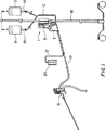
図1は灌注ポンプシステムの図である。
図2は灌注ポンプ制御器の前面図である。
図3は灌注ポンプ制御器の側面図である。
図4は制御器のヒンジ留めフレームを開放状態で示す詳細図である。
図5はヒンジ留めフレームが開放状態にあり、使い捨て式ポンプボディが定位置にある制御器の詳細な側面図である。
図6は制御器の底面図である(明瞭化のためにヒンジ留めフレームは図示しない)。
図7はS字状パドルの詳細な図である。
図8A−8Fは様々な一連の隆起を示す様々なポンプボディの上面図である。
図8Gはポンプボディの上面の隆起の詳細である。
図9Aは腹腔鏡検査ポンプボディの上部を破断して示す図である。
図9Bは腹腔鏡検査ポンプボディの側面図である。
図10は一般的なポンプボディの底面図である。
図11は一般的なポンプボディの出口の詳細な図である。
図12Aは関節鏡検査ポンプボディの上部を破断して示す図である。
図13Aは子宮鏡検査ポンプボディの上部を破断して示す図である。
図13Bは子宮鏡検査ポンプボディの側面図である。
図14は制御器電子機器の模式的ブロック図である。
図15はROMメモリの例示的な配置の模式図である。
例示実施例の説明
図1は、全体的に符号1で示される灌注ポンプシステムを図示する。典型的な使用では、ポンプボディ5が取り付けられたポンプ制御器3をI.Vポール18に取り付けることができる。この配置構成では、灌注流体貯留バッグ8をポンプボディ5の上方に吊すことができるので、灌注流体を重力によって可撓配管系10内を流動させて、ポンプ5へ充填させるようにすることができる。その可撓配管系10は、バッグスパイク14をバック8に挿入することにより、灌注流体貯蔵バッグ8へ接続し得る。加圧された流体は可撓配管系12を通じてポンプボディを出る。ここで可撓配管系12は灌注ハンドピース16へ取り付けられており、このハンドピースによりオペレーターは灌注流体流を外科処置サイトへ向かわせることができる。この灌注ハンドピース16は、単純な延伸したラテックス配管としてもよい。
制御器3は、その前方のボタンを押すか、或いは導線21により制御器3に接続された使い捨て式の遠隔制御ユニット20を用いることにより操作できる。灌注ハンドピース16上に位置する遠隔接続されたオン−オフスイッチ(図示せず)の使用により、ポンプへの電力を制御することも可能である。
図2および図3は、灌注ポンプ制御器3の外観をより詳細に示す。回転シャフトを有する通常の電気モータ(図示せず)と、このモータの作動を制御する論理回路系とが制御器3のハウジング25内に位置している。ハウジング25の前面に位置しており、膜スイッチとし得る制御パネル23は、ポンプシステムを操作するためのボタン29,31,33,35および37をオペレーターへ供する。何れか或いは全てのボタンには、そのボタンについての機能が作動していることを表示する集積LEDライトを設けることができる。制御器3はクランプ50によりI.Vポール18へ取り付けることができ、そのクランプ50はノブ48により緊結または弛緩させることができる。主電源スイッチ44および遠隔制御配線レセプタクル46は、ハウジング25の側部の窪んだ部分に配置させてあり、注流体貯蔵バッグ8から不意にこぼれた灌注流体が、ハウジング25の側部を伝ってしたたり落ちて、スイッチ内へ浸み込んで短絡或いは腐食を引き起こすことがないようにしてある。更に、これらの電気的部品は、エラストマー被包体(図示せず)で覆うことにより、流体の浸透から保護するようにしてもよい。
制御器ハウジング25の底部は、U字状フレーム41であり、このフレームは、その後方縁42に沿ってヒンジにより制御器へ連結されている。図2は、フレーム41が「閉止」即ち作動状態にある制御器を示し、一方、図3は(仮想輪郭線で示す状態で)フレーム41を「開放」即ち呼び水(priming)状態で示す。図4は、後方ヒンジ54により制御器ハウジング25へ取り付けられたフレーム41を開放状態で示す。図3における仮想輪郭線で示すように、フレーム41は水平に対して約45°の角度へ開放する。このフレーム41は、閉止状態においては、ばねで偏倚された解除ラッチ39により、制御器ハウジング25の底面に対して実質的に面一の状態に保持される。解除ラッチ39の内方突出フック65は、フレームの前方縁60を捕捉して、このフレームを閉止状態に保持させる。ラッチ39の縁は、外側へ曲がった開閉部をなすように設計されており、その開閉部の両縁が同時に係合して、しっかりと把持するようにされている。
図4および図5に示されるように、フレーム41の外縁51は、制御器ハウジングの底部の形状に倣うように輪郭付けされている。しかしながら、このフレーム41の内縁58は、制御器と共に使用される様々な使い捨て式ポンプボディ5の全てに共通なボウルフランジ62上の位置決め隆起(locating ridge)の外側形状に合致するように輪郭付けされている。覆板上に円形の位置決め隆起(この位置決め隆起は図5に示すような或るポンプボディ設計の外側の外側形状を含み得る)を設けると、フレーム41の内縁も円形にされ、しかもポンプボディを確実に保持するように僅かに大径にされる。他のポンプボディ形状、ボウルフランジおよび覆板隆起形状も本発明の要旨と目的から逸脱することなく使用できる。制御器ハウジング25内に装着された緩衝器67は、ヒンジ54の位置にてフレーム41に係合して、ボタン39が解除されたときにフレームが唐突に開放することを防ぐと共に、フレームの移動を水平から約45度に制限させる。
ポンプボディ5の装填は、フレーム41が開放状態にあるときになされる。ポンプボディへ接続させる入口および出口ライン10,12は、各々フレーム41の小開口57を通すことができ、且つポンプボディ5全体を上方からフレーム内へ降ろすことができる。ポンプボディの外縁の周囲のボウルフランジ62の縁81が、フレーム41の表面56へ接触することにより、ポンプボディはフレーム内の適切な深さにおいて保持される。図4に示された可撓パッド52をフレームの表面56上の位置に配置して、表面欠陥を埋め合わせて、フレームが閉止したときに、制御器ハウジングの底面68に対してボウル5の確実な配置が保証されるようにしてもよい。図5は、使い捨て式ポンプボディ5が装着されたフレーム41が開放状態、即ち呼び水状態にある制御器3を示す。
ポンプボディ5が装填された状態で、フレーム41が閉止すると、ポンプボディ5と制御器3の下面との間に幾つかの重要な相互作用が生じる。最初に、ポンプボディ5の覆板87から突出する隆起80が、制御器3の下面に配列されたスイッチの少なくとも一つに接触してこれを押し下げる。このスイッチ配列は、制御器ハウジングの下面図である図6に示されており、その配列は複数のスイッチ69からなる。様々な医療処置のために意図された種々の形式のポンプボディをフレーム41内に配置して制御器3と共に使用することができるので、制御器3は、スイッチ69が押し下げられたパターンによって、何れの形式のポンプボディが装填されたかということを識別できる。
図8A−Fは覆板87の上部に成型し得る隆起の種々のパターンを示す。六つの代表的なパターンが図示されている。これらのパターンは、図6に示された四位置矩形スイッチ配列と共に作動するが、これとは異なる数のスイッチを本発明の要旨と目的とから逸脱することなく用いることができる。図8Gに断面図で示すように隆起は覆板87の上面から突出する。ここで図8Gは図8Bにおける上部隆起の断面図である。各々のパターンは、特定の処置のために設計された一つのポンプボディ型式に対応させることができる。例えば、図8Aに示された隆起には、関節鏡検査処置での使用のために設計されたポンプボディを選定し得る。図8Bに示された隆起パターンには、腹腔鏡検査処置での使用のために設計されたポンプボディを選定し得る。他の隆起パターンを他の処置に対応させることが可能であり、若干のパターンを将来設計されるであろうポンプボディのために確保しておいてもよい。幾つかの例示的な隆起パターンを図8A−8Fに示したが、スイッチの四位置矩形配列には他の隆起パターンも可能である。更に、他のスイッチ配列を他の隆起パターンと組み合わせて使用することができ、これらの全ては本発明の要旨と目的から逸脱するものではない。
隆起の存在が論理「1」を表し、且つ隆起が存在しないことが論理「0」を表すとすれば、隆起のパターンは2進数を表す。制御器内の2進論理は、押し下げられたスイッチを読み取ることにより、何れの型式のポンプボディが装着されたかということを解明する。この情報により、制御器は、装着されたポンプボディが意図している処置の形式をLEDスクリーン27上に表示する。ここでユーザーは、これが意図された処置である(即ち正しいポンプボディが装着された)ことを確認せねばならず、この確認は、制御器の制御パネル23上に確認ボタン37を押すことによりなされる。その後、制御器は、その形式の処置に適切な初期デフォルト流体圧を発生するであろうモータ速度を選択する。この圧力はLEDスクリーン27上に表示される。次いでユーザーは、スタートボタン33を押してポンプ操作を開始する。操作期間中に増加ボタン29または減少ボタン31を押すことによって、圧力もユーザーにより変更し得る。ポンプを停止させるためには、ユーザーは停止ボタン35を押す。
更に詳しくは、制御器の下面上に配置されたスイッチ69(例えばGray Hill,Inc.社によって市販されている部分番号39−701)は、プラスチック駆動ステムを有する押しボタンスイッチであり、そのプラスチック駆動ステムは、幾つかのまたは全てのスイッチを選択的に作動させるように、ポンプボディの覆板87上の同一の隆起80と同軸にされている。このスイッチは、スイッチの閉止および開放のパターンを検出するプログラマブル論理デバイス(programmable logic device;以下、「PLD」)に接続されている。図示の実施例と共に使用するのに適する一つのPLDは、カリフォルニア州サンホゼのXilinx Inc.によって市販されているXilinx(商標名)プログラマブル論理デバイスである。このPLDと回路系の残りの部分は、通常の電源から電力を供給され、その電源は、電圧サージの場合にユニットを遮断するクローバー回路のような安全機構を持ち得る。
制御器の電子系の一般的な配置は図14に示される。主な要素は、プログラマブル論理デバイス1400、消去可能プログラマブルリードオンリーメモリ(EPROM)1402、モータ制御器1404、モータ1406および電源1408である。LEDディスプレイ1412と膜キーボード1414とを含むユーザ・インタフェース1426もある。遠隔制御器1416も同じく制御器で使用することができる。PLD1400は、アドレスバス1418上にアドレス信号を発生し、そのアドレス信号はEPROM1402へ与えられて、データがEPROM1402からPLD1400へデータバス1420上を帰還する。PLD1400は、リード線1422によりディスプレイドライバ1412も制御して、キーボード1414または遠隔制御器1416からのデータを各々1424および1426によって受け取ることができる。
PLD1400はモータ制御器1404によってモータ1406を制御する。次いでモータ制御器1404はモータ1406を操作する駆動電流を発生する。モータ1406の状態は、モータ1406内のセンサによって決定され、閉ループモータ制御を与えるようにリード線1432を介してPLD1400へ戻される。
PLD1400は、隆起によって押し下げられたスイッチのパターンを電子的に読み取るプログラマブル論理デバイスであって、各々のスイッチパターンについて独特なアドレス単語をアドレスバス1418上に生成する。PLD1400がポンプボディの有無を検出するために、ポンプボディは、どのポンプボディが存在しているときでも一つのスイッチが常に押し下げられているよう配置される。例えば図8Aに示される隆起8は、図8A−8Fに図示される何れの隆起パターンにも存在する。制御器におけるポンプボディの不在は、PLD1400に、LEDディスプレイ27上に単語「LOAD(装填)」の表示を生成して、且つ「停止」ボタン35を照明させるようにディスプレイドライバ1412を制御させる。このスイッチはモータ保全インターロックのためにも使用され、このインターロックは、制御器が作動状態にある間にユーザーがフレーム41を開いてしまったら、モータ1406からの帰還ライン(図示せず)を開放する。
一つのスイッチが隆起81によって押し下げられたとき、PLD1400は他のスイッチの状態に基づいてバス1418上にアドレス単語を生成する。アドレス単語は順次に、EPROM1402に与えられ、メモリ内に恒久的にプログラムされた複数の検索(ルックアップ)テーブルの一つにアクセスするために使用される。各々のポンプボディは、EPROM1402内に、その検索テーブルがロードされた専用のセクションを有する。EPROM1402は、解読されたスイッチパターンにより、特定のポンプボディ検索テーブルを処理する。
EPROM1402の一般的な配置は図15に示される。EPROM1500は下半分が8から2000の16進バイトブロック1502-1516に分割され、上半分1518がPLD形態データのために確保されている。図示のように、例示的なテーブルは、関節鏡検査処置(テーブル1504)、一般的な処置(テーブル1506)、腹腔鏡検査処置(テーブル1508)、パルス出力を必要とする処置(テーブル1510)、子宮鏡検査処置(テーブル1512)、将来の処置のために確保された二つのテーブル(テーブル1514および1516)のために示されている。制御器が最初に駆動されたとき、PLD1400は、アドレスバス1418が、ディスプレイ27に単語「LOAD(装填)」に続いて表示されたテストパターン”★★★★”を表示させる特定のメモリ位置をアドレスするようにプログラムされている。このテストパターン”★★★★”および単語「LOAD」は、全てのポンプボディテーブル1502-1516内に、各々のテーブル内の同じ位置においてプログラムされている。それ故に、何れのテーブルがスイッチパターンによって選択されたかに拘らず、テストパターンおよび単語「LOAD」は常に生成される。何らかの理由のために、誤った低いアドレスが生成されるならば、デフォルトテーブル1502が空白であるとして、エラーパターン”−−−−”が表示される。制御器開始ルーティンが終了した後、アドレスバス1418はディスプレイ27に表示された単語「LOAD」で解除されて、制御器は、最初に装填されるポンプボディのために待機する。
ひとたびポンプボディが装填されたならば、アドレスバス1418はPLD1400内に恒久的にプログラムされた解読回路を通じてスイッチにより直接にアクセスされる。特に、ポンプボディを装填して、且つフレーム41を閉止することは、スイッチ69の組み合わせを起動させる。四つのスイッチのうちの三つがアドレスバス1418内でアドレスラインを直接に制御して、七つのテーブル1504-1516の一つの開始にアクセスする。各々のテーブルがポンプボディ形式の一つに対応して、例えば、外科的な適用のような特定のポンプボディ、デフォルト開始圧力、圧力測定尺度に関係があるポンプボディパラメータを含む。各々のテーブルが、順次に同様な手法で整えられる。各々のテーブルの最初のメモリ位置は、対応するポンプボディの名称を含み、この名称は四つの省略文を用いている。この名称に続くのは、そのテーブルの最初のアドレスからポンプボディについてのデフォルト速度と最大速度とのアドレスオフセットである。検索テーブルに格納された圧力測定尺度のパラメータは、各々のポンプボディのために用いられる圧力単位を含み得る。例えば、圧力単位は関節鏡検査、腹腔鏡、または子宮鏡検査の適用のためには、水銀ミリメートルとし得る。一方、拍動適用のための圧力単位は、例えば「低」、「中間」「高」と指示され得る。圧力測定尺度のパラメータは、意図された医療処置に基づいて各々のポンプボディについての最大および最小出力値を含み得る。関節鏡検査適用は、例えば、70ミリ水銀柱から300ミリ水銀柱の範囲の圧力を必要とするであろう。
使用されたポンプボディに関係のある情報をユニットの前面上の発光ダイオードディスプレイに表示させるために、外科処置を表す単語がLEDディスプレイドライバへ与えられる。例えば、LEDディスプレイは、関節鏡検査(arthroscopic)処置のために単語「ARTH」を、腹腔鏡検査(laparoscopic)処置のために単語「LAP」などを発生し得る。次いでPLDは、ユーザーが制御パネル上の処置確認ボタン37(図2)を押すのを待つ。処置確認ボタンが押されるまでは、ユニットは処理を進めない。
更に詳しくは、PLD1400の特別にプログラムされた部分は、クロックによって駆動されている。PLD1400は、順次に、検索テーブルに格納されたデータを、PLD内に与えられた書き込みパルスを用いてディスプレイドライバ1412に適用させる。各々の検索テーブルは16バイトのデータを持っている。ディスプレイドライバ1412は、二つの単語、即ち上部の単語と下部の単語とで作動する。EPROM1402内の選択された検索テーブル内のデータの最初の10バイトは、書き込みパルスを用いてディスプレイドライバ1412へ出力される。最初に下部表示単語が選択されて5バイトが出力されてから、上部単語が選択される。10バイトの表示データが与えられた後、テーブルの開始位置からオフセットしたデフォルトメモリについての2バイトが、低バイトが最初に、次いでテーブルの長さ(高いテーブル入力)を表す2バイトがPLD1400に出力される。
PLDが確認ボタンの押し下げを検出するとき、PLDは、ROMから検索されたデフォルト開始圧力値を表示させるようにLEDディスプレイを制御する。特に、デフォルトメモリ位置におけるデータがロードされる。例えば、デフォルト圧力のために10バイトがディスプレイドライバ1412へ与えられる。検索された次の2バイトは、その圧力のためにモータ速度を設定する。次いで「停止」ボタンが照明され、「開始」ボタン33は照明されない。ここで制御器は内部電気モータを始動させる準備ができている。モータは、ユーザーが「開始」ボタンを押し下げるときに実際に始動させられる。
「開始」ボタンが押し下げられているとき、PLDは、装着されたポンプボディについて検索テーブルから得られたデフォルト開始圧力によりモータを制御するモータ制御回路へディジタル単語を伝達する。デフォルト開始圧力は、アップ/ダウンカウンタにも予めロードされている。モータ制御回路は、例えば、ディジタル信号をD.C.モータ駆動電流に変換する商業的に入手可能な集積回路とし得る。例示の実施例での使用に適したモータ制御回路は、モトローラ(Motorola)社によって市販されたブラシレスD.C.モータ制御回路(Brushless D.C. Motor Controller Circuit)、部品番号MC3035である。このモータは、回転位置を検知するホール効果センサを有する三相ブラシレスD.C.モータである。そのセンサの出力は閉ループ速度制御のためにPLD1400へ与えられる。
ユーザーが「処置確認」ボタンを押し下げることにより、選択されたポンプボディが適正であることが確認された後、ユニットの操作は、ユニットの前面上の制御パネルか、或いはレセプタクル46(図3)へ差し込まれる可撓導電ケーブル2によりユニットへ接続された遠隔制御器の何れかによって制御し得る。遠隔制御器上のキーパッドは、何らかの公知のスイッチングデバイス、例えば導電性薄膜形式スイッチとしてもよい。遠隔制御器は好ましくは開始ボタン、停止ボタン、昇圧ボタンおよび減圧ボタンを含み、遠隔制御器上のスイッチは、制御器制御パネル上のスイッチに並列に接続されている。遠隔制御器20を制御器3内の電源から電気的に隔絶するために、遠隔制御器20を制御器3へ接続する全ての電気的リード線には、光カプラ(例えばテキサス州ダラスのテキサス・インスツルメンツ社製の部品番号TIL903)が包含されていることが好ましい。この電気的な隔絶は、遠隔制御器20を保持するであろう操作要員が、制御器3内で電気的的短絡が生じた場合に電気的衝撃を被る可能性を防止または軽減する。
操作の間に、ユーザーは増加ボタン29または減少ボタン31を押すことにより、モータの回転速度を変更できる。増加および減少ボタン29,31は、モータのRPMを直接に変化させることにより、出力圧力を変化させる。操作の終わりには、減少ボタン31が押されるとき、PLDは、アドレスバス1418の上に配置される新たなEPROMアドレス位置を生じさせるようにアップ/ダウンカウンタを減少させることにより応答する。新たに処理された情報は次いでディスプレイドライバ1412およびモータ制御器1404へロードされる。PLDは、最小出力値が予めロードされている比較回路をも含む。減少したアップ/ダウンカウンタ値は、最小出力圧力値と比較される。減少された値が、最小圧力値以上であるならば、減少された値はモータ制御器へ伝達されて、モータの回転速度を減速させることにより、ポンプ出力圧力を減圧させる。更に、この減少された値は、LED駆動回路系へ与えられて、LEDディスプレイに新たな値に対応する表示を発生させる。これに代えて、減少させられた値が最小圧力値より小さいならば、カウンタは選択を取り消される。同様なルーティンが、ユーザーが増加ボタン29を押す場合に続行される。
装着されたポンプボディ5と制御器3との間の他の重要な接続機構は、制御器内の電気モータから使い捨て式ポンプの圧送機構までの動力の接続機構である。ひとたびフレーム41が閉止して、ポンプボディ5の覆板87が制御器の下面68に対して押圧されると、ポンプ駆動ロッド82の突出端は制御器のS字状パドル71に接触するように整合される。図5,6および7を参照すると、ひとたびモータ76に動力が与えられると、モータシャフト73およびS字状パドル71が回転する。パドルの回転に応じて、ポンプ駆動ロッド82の端部がパドル71の凹所縁94に接触することになる。次いでパドルが電気モータの動力の下に回転するにつれて、ポンプボディ5の駆動ロッド82がポンプ内の圧送動作を生起するように作動する。
覆板87と制御器3の裏面68との間の他の重要な接続機構は、それらの表面の間の確実な接続である。リップ60とラッチ39のリップ65との係合により、フレーム41が閉止すると、ポンプボディ5の覆板87は制御器ハウジング25の下面68に接触することになる。フレーム41の上縁表面56がポンプボウル位置決め隆起83の底部に対して上向きの力を維持する状態で、ポンプボディ5は制御器へ固着される。可撓パッド52は、面の間の完全なインタフェースが存在することを保証する。パッド52上の直立隆起は、このインタフェースを部分的にまたは完全に押し込むようにする。
操作の間、流体の浸出がポンプボディ5の覆板87から生じるなら、制御器の底部との強固なインタフェースが流体の流出を充分に迅速に妨げる。覆板87と制御器の底部との間に溜まった流体は、スイッチ69と、モータシャフト73回りのシール(図示せず)への流体の侵入を招いて、制御器部品の損傷させるであろう。この潜在的な問題を回避するために、幾つかの通路90を制御器ハウジング68の下側に窪めて形成することにより、流体が逃げるスペースを与えて、制御器の後部から流体を安全に吐出させるようにしてある。更に、流体漏洩の潜在的な損傷の影響からスイッチ69を保護するために、これらスイッチを覆うようにエラストマー包囲体を配置してもよい。
腹腔鏡検査処置に用いるための使い捨て式のポンプボディを図9Aおよび9Bに示す。到来流体ライン10はポンプボディに入口112にて接続され、その入口112はT字状回転インペラ84の中空シャフト115に流体連通している。流体は、中空シャフトを通って移動し、次いで翼85を通過する導管108を通って放射状に外側へ移動する。円筒状レセプタクル109が、ポンプボディの底壁内に成形されており、インペラ84の中空シャフト114を保持する。シャフト114とレセプタクル115との支持面における低摩擦プラスチック材料の使用と、接触面の間の流体の存在とは、使用期間中にベアリングがくっついて停止する(seizing)ことを防止する。ポンプボディと覆板との全体は、支持面と同様な材料から形成される。
流体は、遠心ポンプの役割を果たす回転インペラから放射状に導管108を出て、圧送チャンバ内の圧力を生成する。その圧力は、翼85の長さと、回転インペラの回転速度、乱流の付加的な効果とに関連している。加圧流体は、圧送チャンバの外側壁の内室に位置した出口110を通じて圧送チャンバ86を出る。以下に詳述するように、内壁98がポンプボディ壁へ成型されており、これは、ポンプボディ5が制御器内に装着されたときに、流体出口110が圧送チャンバ86の覆板87の近傍に位置することを保証する。流体出口の位置は、便利なことに、本発明における呼び水手順中にポンプボディから空気を追い出すこと可能とする。
圧送チャンバ86の上部は、この圧送チャンバと同様な材料からなる覆板87により封止されており、ポンプチャンバへ超音波溶着または接着剤により結合されている。
ポンプ駆動機構は、ポンプボウル全体の完全な液密性を維持する方式で、インペラ84へ向かって覆板87を貫通させねばならない。ポンプ駆動ロッド82は、覆板87の中心における開口を覆う可撓ダイアフラム102を貫通する。このダイアフラム102は、覆板87の開口を覆って位置し、覆板87の上部に接着剤または超音波溶着により接着されたフランジ106により、覆板の上面に対して捕捉される。このダイアフラム102は、覆板87の上面とフランジとの間で圧縮される。
図9Bに示すように、駆動ロッド82は、ダイアフラムに一体成型された円筒状スリーブ103を貫通してインペラ84内の開口88に係合する。カラー104が、ダイアフラムのスリーブ103を取り囲んで、このスリーブを駆動ロッド82の表面との確実な接触に保持するので、液密シールが形成される。駆動ロッド上の環状リブ100は、カラー104の上部に当接し、輸送期間中にカラー104がスリーブ103から滑落することを防止すると共に、作動中にポンプボディ内で生成される圧力によりダイアフラム102が上方へ付勢されないようにする。
駆動ロッド82は、制御器3の回転S字状パドル71からポンプチャンバ86内の回転インペラ84へ動力を伝達する。ポンプボディが制御器3の下面に取り付けられたとき、インペラ84およびS字状パドル71は、共通の回転軸を共用する。しかしながら、駆動ロッドは、回転軸からオフセットした位置でインペラ84およびS字状パドル71に接続され、この駆動ロッドが回転軸を斜めに交叉するようにされている。従って、S字状パドル71がモータからの動力の下で回転するのに応じて、駆動ロッドが回転し、それによりインペラを回転させる。駆動ロッドがダイアフラム102のスリーブ103内の回転というよりもむしろ章動運動をするので、表面相互間の液密な接続は、封止面が相互に移動しないように、一層容易に維持することができる。ダイアフラム102は、断面を波形状(例えばS字状)に形成して、駆動ロッド82の章動に起因してダイアフラム102を撓曲させて張力を低減させるようにすることができる。この波形状は、回転が生じるときに、圧縮されて、そして反対側に伸長される。部品における低摩擦材料の使用と、圧送チャンバ86が流体で充填されたときの駆動ロッド/インペラ接続における流体の存在との組み合わせにより、この接続においては摩擦が低減される。
シャフト82をモータシャフト73の縦軸に対して30度の角度に向けることは満足な性能結果をもたらした。従って、図7に示されるように、傾斜したシャフト表面94Aも角度30度で傾斜させて、シャフト82の外表面に接触させるようにすることが好ましい。シャフト82が傾斜表面94Aとの接触を損なわれないように、封止フランジ71aをパドル71上に含めてもよい。
好適実施例においては、流体の逆流を防止する一方向流体弁は、システム全体に亘って存在しない。それ故、貯蔵袋8からポンプ5、配管系12およびハンドピース16を通る流路は、システムが作動している際に、妨げのない流体流路を形成しているものと見なし得る。従って、ボディキャビティ内に形成される不所望な過剰な圧力も、灌注流体がそのキャビティに入るように、圧力率を減少させられる。
全体的な設計実施態様を利用する他の様々な医療処置のために特に設計されたポンプボディが図12A,12Bおよび13A,13Bに示されている。図12Aおよび12Bに示されたポンプボディは関節鏡検査処置での使用のために設計されている。これは、その形状、設計および寸法が、図9Aおよび9Bに関連させて説明した腹腔鏡検査ポンプボディに類似している。関節鏡検査ポンプボディ119は、上述の腹腔鏡ポンプボディで用いたインペラ84よりも短い翼121を有するインペラ120を採用する。この設計変更は、ポンプ性能を最適化して、関節鏡検査の使用に望ましい減圧された圧力を役立てる。ポンプによって生成された流体圧は、翼の長さと回転速度とに関係しているので、所定のポンプボディについては、ポンプによって生成された流体圧は回転速度に依存している。しかしながら、所望の出力圧力範囲をモータの回転速度範囲内に充分に収まる回転速度値へ最適化するためには、異なる翼長を有するポンプボディを使用することが望ましい。より長い翼長によれば、モータを非常に速い回転速度で駆動させることを必要とせずに、より高い圧力を発生させることができる。しかしながら、ポンプボディ119は特定の医療処置のために最適化されているものの、覆板87と、位置決めボウルフランジ隆起(この場合はポンプボディの外側)は全てのポンプボディについて同様であるそれらの特定の寸法は、異なるポンプボディを同一の制御器ユニットに交換可能に用いることを可能とする。
図10は腹腔鏡検査および関節鏡検査ポンプボディの底面図である。ポンプボディの底部へ構造的支持体を与えるように成型される間に、肉厚にされた一組のリブ116が壁に形成されている。付加された構造的支持体は、使用中にポンプボディが加圧されたときに底壁の撓みに起因するポンプ出力圧力の変動を防止する。付加された構造的支持体は、組立体全体の撓みを最小化して、それがパドルから離れないようにする。
更に、ポンプボディは特定医療処置のために他の方式で最適化し得る。子宮鏡検査の使用を意図したポンプボディ124が図13Aおよび13Bに示されている。子宮鏡検査処置のために使用されたポンプ124は、前述した腹腔鏡検査処置および関節鏡検査処置に使用されるポンプよりも実質的に直径が小さく、また異なる形状を有するポンプチャンバ128を採用する。特に、半球形状を有する小さなポンプチャンバ128は、子宮鏡検査処置で必要とされる低圧において作動されるときに、他の場合(より大きなポンプチャンバの場合)に起こり得る気泡形成の量を低減するのに役立つ。過剰な気泡はポンプチャンバ内の実質的な圧力変動を引き起こし、ポンプの性能に不都合な影響を及ぼす虞がある。ポンプチャンバの半球形状は、ポンプチャンバ内の流体の澱みの低減にも役立つと共に、その小さな寸法は、最大圧力を安全限界に制限させる。充分に小さな寸法の故に、小さな容積の呼び液(priming solution)が必要としない。また、その量は臨床的に制御され得る。
ポンプチャンバ128の全体は、上述した他のポンプボディよりも小径であり、子宮鏡検査ポンプボディ124の覆板132は、制御器3のフレーム41内で互換性を維持するように寸法付けられている。覆板132の全体的な直径は、他のポンプボディに用いられた蓋と同様である。更に、覆板132は、上述の大きなポンプボディで用いられたポンプボディのフランジの外径に対応する下向き延伸位置決め隆起130を採用する。それ故に、位置決め隆起130の表面は、フレーム41の環状縁58内にしっかりと嵌合している。この子宮鏡検査ポンプボディの他の全ての特徴は、腹腔鏡検査ポンプボディに関連して上述したものと同様である。
発明の一つの観点によれば、全てのポンプボディは自動呼び水(automatic priming)のために設計されている。特に、呼び水手順の間に空気はポンプボディから追い出される。図11は、腹腔鏡検査と関節鏡検査とのポンプボディのポンプチャンバ内に採用された嵩上げ出口(elevated outlet)110の細部を示す。ポンプチャンバの内部上の壁98は、チャンバのまさしく上部のみから出口110を通して流体が出ることを保証する。同様な方式で、子宮鏡検査ポンプボディも図13Bに示すように嵩上げ出口136を採用する。ポンプから排出された流体は出口ポート134を通じて下方へ移動して、次いで出口ライン12を通る。幾つかのポンプボディのポンプチャンバの縁上の嵩上げ出口位置は、以下に詳細に説明される装填手順中に、ポンプチャンバに流体を呼び水するときに、気泡を排除することに特に効果がある。
制御器と共に使用するためにポンプボディを装填するには、ユーザーは先ず、解除ラッチ39を押し下げることにより、フレーム41を図5に示される開放位置へ降下させるようにして、フレーム41を開放する。次いでユーザーは意図された処置のために適切なポンプボディを選択して、入口ラインおよび出口ラインをフレーム41の開口57に通過させることにより、フレームにポンプを挿入する。次いで、ポンプチャンバがフレームの丸み付け縁58内に収まるように、且つポンプボディのボディ隆起83がフレーム41の表面56に接触するように、ポンプボディをフレームへ降ろせるであろう。正しく組み込まれるとき、ポンプボディの出口ラインは、図5に示されるように、フレームのヒンジ54の近傍で制御器の後方へ向けられる。開閉体の開放位置とポンプボディの対応する角度的な向き付けとは、図5に示すように、流体出口をポンプチャンバの最も高い位置に自動的に位置させる。ポンプボディが、このポンプボディよりも高所にある灌注貯蔵器にひとたび接続されると、流体が重力の下にポンプボディへ移動して、ポンプチャンバの中心において入口ライン10へ入る。この流体は、インペラ84を通って上昇して、チャンバ86を最も低い位置から充填し始めて、このチャンバを満たす。ポンプチャンバ86内の液面レベルが上昇するにつれて、空気は、上昇する流体に取って代わられるようにして、チャンバから排出される。チャンバ内の最も高い位置に配置された出口により、チャンバ内の空気は、空気を排出可能な出口を有する。全ての気泡は、チャンバ86から効率的に追い出されるので、チャンバが完全に流体で満たされたときには、チャンバ86内に捕捉された気泡が残らないようにされる。この工程は、ユーザーの最小の労力により、ポンプチャンバへ流体を自動的且つ効率的に呼び水する。
ポンプチャンバがひとたび呼び水されると、フレーム41は上方へ閉じて、ラッチ39に係合する。閉止した途端に、起動している制御器は、(覆板ポンプボディの上部の隆起の配列により係合して)押し下げられたスイッチの配列を認識することにより、何れの形式のポンプボディが取り付けられたかを識別すると共に、制御器動作を上述したようにして開始できる。
以上の本発明の説明は、図示および説明のみを意図したものであるが、本発明の要旨から逸脱することのない他の実施例、変形例および使用例は、当業者には明白であることに留意されたい。
以上本発明を記載したが、本発明を特許により権利として請求をせんとするところのものは: Field of Invention
The present invention relates to irrigation pump systems and, more particularly, to devices used to irrigate surgical sites during medical procedures.
Background of the Invention
Devices that deliver irrigation fluid to the irrigation site are required for various medical and dental procedures. For example, laparoscopy, arthroscopy, and hysteroscopy procedures are sufficient to irrigate the surgical site to hold the tamponade, isolate the bleeders, and generally clean the surgical area. It is necessary to deliver fluid. Laparoscopy procedures involve incision of the abdominal cavity and include appendectomy, cholecystectomy (gallbladder incision) and treatment of ectopic pregnancy. Hysteroscopy procedures involve examination of the uterine cavity, and include the removal of abnormal tissue from the uterus as a biopsy or myomectomy. Arthroscopic procedures are typically performed by an orthopedic surgeon and involve irrigation, enlargement and examination of joints such as in the knee, shoulder, elbow or ankle, such arthroscopic procedures include synovectomy, meniscus Incision or repair of the anterior cruciate ligament.
During these various medical procedures, it is generally beneficial for the surgeon to separate the tissue surrounding the surgical site by injecting a solution such as saline, glycine or lactate Ringer solution into the target tissue. Each procedure requires that different volumes of fluid be administered at different pressures, so for medical personnel to have a single pump that can be adapted to provide proper irrigation for different procedures Is beneficial.
Another important aspect of medical irrigation pumps is sterilization. The fluid that enters the tissue during the surgical procedure must be kept sterile. However, when using expensive hardware such as a pump, the effort to maintain sterility is complicated. If the medical device that delivers the irrigation fluid to the body is disposable after each use, sterilization is more easily and reliably maintained. One medical irrigation pump that can be used utilizes a permanent non-sterile pump motor that can generate a pumping action in a disposable sterilization channel that is removable from the permanent motor hardware. .
U.S. Pat. No. 3,927,955 (Spinosa et al.) Discloses a medical cassette pump that utilizes a peristaltic pumping action that pumps fluid through a sterile path. This pump consists of a non-sterile permanent electric motor that rotates a planetary roller. The rollers engage the surface of the sterilization flexible piping system that is held around the annular outer edge of the disposable cassette. A fluid pumping action is provided such that the rollers compress the piping system against the edge of the cassette. Since the cassette and piping system are removable from the rollers, they can be discarded and replaced with a new sterilization cassette and piping for each use.
U.S. Pat. No. 4,635,621 (Atkinson) discloses a wash pump system that utilizes a permanent electric motor that engages a disposable sterilization pumping unit. A linear reciprocating electric motor releasably engages the end of a piston rod that is part of a piston / cylinder disposable pump. The replaceable sterilization washing pump slides into a compartment adjacent to the electric motor so that the motor and piston rod can be maintained in an operating relationship. It would be highly desirable to provide a medical pump that can drive a variety of replaceable sterilization pumping mechanisms to assist in the many medical procedures that medical personnel must perform.
Summary of invention
The present invention relates to a sterilization disposable pumping mechanism and a fluid pump used for medical treatment employing a sterilization permanent pump motor that interacts with a flow path. This pump system utilizes sophisticated electronic controllers that provide power to the rotating electric motor. The controller and motor comprise a support designed to receive one of a plurality of disposable sterilization pumping mechanisms or bodies that are connected to and become part of a sterilization channel through which the irrigation fluid flows. Sterile irrigation fluid may be supplied from the irrigation bag or bottle to the pump body through a flexible tubing. The irrigation fluid is pumped through the sterilization pump body and then moves through the flexible tubing to the irrigation handpiece appropriate for the procedure being performed. All elements of the flow path (irrigation bag, pump body, handpiece, and flexible tubing connecting them) are sterilized parts that can be disposable after a single use.
Several differently configured pumping mechanisms or pump bodies can be used in the motor / controller system. Centrifugal pumps that utilize a rotating impeller to create a controlled fluid pressure and flow rate are used for laparoscopic, hysteroscopy, and arthroscopic procedures. However, depending on each treatment requiring a specific fluid delivery pressure and flow rate, three different pump types, each utilizing a sized impeller, are used. Other pumping mechanisms can also be used with the controller, and those pumping mechanisms can also be configured to produce a fluid output that is particularly suitable for a particular medical procedure.
Permanent controllers can house various disposable pump bodies in specially shaped retainers attached to the bottom of the controller. More particularly, the frame hinged along the rear edge of the bottom of the controller is opened and tilted downward to receive the disposable pump body. Each pump body type has a different internal shape suitable for the procedure for which it is intended, but the outer dimensions of all pump body types are the same so that each pump body fits within the controller frame. Has been. Once the pump body is in the lowered frame, the frame is closed upward and latched so that the pump body engages the controller and drive motor.
The pump body is interfaced to the controller in several ways. First, the pump motor engages the pump drive member of the disposable pump. A paddle attached to the end of the rotary motor shaft captures and rotates the pump drive rod protruding through the top of the pump body. Thereafter, when the electric motor rotates, the rotating paddle rotates the pumping mechanism, which in turn creates a flow of fluid through the predetermined pump body and delivers it to the fluid outlet at a controlled pressure. The fluid delivery rate and pressure can be varied within the limits determined by the pump body design design by increasing or decreasing the rotational speed of the motor.
The controller automatically identifies which type of pump body was inserted and, based on that recognition, sets the initial default motor speed and the upper and lower motor speed limits to appropriate levels. The disposable pump body is interfaced to the controller in two ways. The identification is accomplished by a switch located at the interface between the controller and the pump body, which detects which type of pump body has been installed in the controller. In particular, a small ridge molded on top of each pump body in a pattern specific to each pump body type engages an array of switches located on the underside of the controller. When the hinged frame closes to engage the pump body to the controller, the ridge operates the switch in a predetermined pattern that is unique to that particular pump body. The depressed switch pattern is used to retrieve identification information and default settings from a non-volatile storage device located within the controller. The retrieved information is used to drive the LED display, and medical procedures (eg, laparoscopic, hysteroscopy, arthroscopy, etc.) corresponding to the installed pump body type are displayed on the LED display. Display and notify the user. As a safety feature, before the pump starts, the user must confirm by pressing the confirmation button that the displayed treatment type is the intended type. Once verified by the user, the controller selects a default motor speed that generates the appropriate fluid pressure and associated flow rate for the given procedure. The upper and lower speed limits are also retrieved from the internal storage to set the maximum and minimum fluid pressures, respectively.
When using this system, the user can easily prepare and operate the desired irrigation pump with minimal preparation time. Once the appropriate pump body type is selected for the desired medical procedure, the user simply connects a reservoir of irrigation fluid, such as saline, lactate Ringer solution or glycine, to the pump body by flexible tubing. The reservoir is mounted above the pump body so that fluid flow to the pump is facilitated by gravity. The user may provide an appropriate irrigation handpiece to the pump outlet via the flexible tubing. The flexible tubing set may include a pre-connect end fitting suitable for quick connection to a medical device attached to a patient. To install the pump body in the controller, the user releases the catch located in front of the frame, which is hinged on the opposite side, and pivots downward in the front. The user then inserts the pump body into the frame.
While the frame remains tilted and open, the pump body is filled with fluid and air is automatically expelled from the pump body to prime the pump. The inclined position of the pump body in the open frame ensures that as the pump body is filled with fluid, the air in the pump body is expelled due to the relative position of the fluid inlet and the fluid outlet. In particular, the outlet line located at the bottom of the pump body is connected to a passage molded inside the pump body at a location near the hinge of the frame, which places the fluid outlet at the top of the pump body. Guarantee that Therefore, fluid flowing into the inlet line at the center of the pump body (transferred by gravity) fills the pump body and bubbles are pushed out to the top of the container and are automatically evacuated through the outlet.
After the priming is complete, the user closes the frame and engages the pump to a paddle attached to the shaft of the electric motor in the controller. The controller automatically recognizes the type of pump body installed, generates a display indicating the treatment that the pump body is intended for, and waits for the user to confirm the treatment. After confirmation, the controller automatically registers the maximum pressure, minimum pressure, and default pump pressure, and the user can initiate the procedure by pressing the other control button that starts the controller motor. When the pump is started, the user can adjust the fluid pressure delivered by the pump by pressing the appropriate increase and decrease buttons on the control panel of the controller. Alternatively, the electric motor can be stopped by pressing a stop button.
One of the general objectives of the present invention is to make use of a permanent non-sterile pump motor hardware and a disposable replaceable pumping mechanism that is sterilized along with all components including the flow path. An irrigation pump system is provided.
Another object of the present invention is to provide a medical irrigation pump system that can be adapted for use in various medical procedures requiring different irrigation flows and pressures.
Another object of the present invention is to provide a medical irrigation pump system that utilizes a controller that has the ability to recognize and identify different pumping mechanisms installed for use in various medical procedures.
Yet another object of the present invention is to recognize which type of pumping mechanism has been installed and to automatically set the appropriate motor speed to safely drive the pumping mechanism for the intended procedure. Is to give a controller.
Yet another object of the present invention is to provide a pump motor controller that can be adjusted by the user to increase the pressure of the irrigation fluid by adjusting the motor speed.
Another object of the present invention is to provide a medical irrigation pump system that allows quick and easy priming of the installed pumping mechanism.
It is another object of the present invention to provide various pumping mechanisms that are suitable for various medical procedures and can be easily connected to conventional irrigation fluid reservoirs and irrigation handpiece assemblies.
[Brief description of the drawings]
The above and other objects and advantages of the present invention will be more fully appreciated from the following further description, which refers to the accompanying drawings.
FIG. 1 is a diagram of an irrigation pump system.
FIG. 2 is a front view of the irrigation pump controller.
FIG. 3 is a side view of the irrigation pump controller.
FIG. 4 is a detailed view showing the hinged frame of the controller in an open state.
FIG. 5 is a detailed side view of the controller with the hinged frame open and the disposable pump body in place.
FIG. 6 is a bottom view of the controller (the hinged frame is not shown for clarity).
FIG. 7 is a detailed view of the S-shaped paddle.
8A-8F are top views of various pump bodies showing various series of ridges.
FIG. 8G is a detail of the bulge on the top surface of the pump body.
FIG. 9A is a cutaway view of the upper part of the laparoscopic pump body.
FIG. 9B is a side view of the laparoscopic pump body.
FIG. 10 is a bottom view of a general pump body.
FIG. 11 is a detailed view of the outlet of a typical pump body.
FIG. 12A is a cutaway view of the upper portion of the arthroscopic pump body.
FIG. 13A is a cutaway view of the upper part of the hysteroscopy pump body.
FIG. 13B is a side view of the hysteroscopy pump body.
FIG. 14 is a schematic block diagram of the controller electronics.
FIG. 15 is a schematic diagram of an exemplary arrangement of ROM memory.
Description of exemplary embodiments
FIG. 1 illustrates an irrigation pump system generally designated 1. In typical use, the
The
2 and 3 show the appearance of the
The bottom of the
As shown in FIGS. 4 and 5, the
The
When the
8A-F show various patterns of ridges that can be molded on top of the
If the presence of a ridge represents a logic “1” and the absence of a ridge represents a logic “0”, the pattern of ridges represents a binary number. The binary logic in the controller reveals which type of pump body was installed by reading the depressed switch. With this information, the controller displays on the
More particularly, a switch 69 (eg, part number 39-701 marketed by Gray Hill, Inc.) located on the underside of the controller is a push button switch having a plastic drive stem and its plastic drive. The stem is coaxial with the
The general arrangement of the controller electronics is shown in FIG. The main elements are a
The
The
When one switch is depressed by
The general layout of
Once the pump body is loaded, the
A word representing the surgical procedure is provided to the LED display driver in order to display information related to the pump body used on a light emitting diode display on the front of the unit. For example, an LED display may generate the word “ARTH” for arthroscopic procedures, the word “LAP” for laparoscopic procedures, and the like. The PLD then waits for the user to press the action confirmation button 37 (FIG. 2) on the control panel. The unit cannot proceed until the treatment confirmation button is pressed.
More specifically, a specially programmed portion of
When the PLD detects a confirmation button press, the PLD controls the LED display to display the default starting pressure value retrieved from the ROM. In particular, data at default memory locations is loaded. For example, 10 bytes are provided to the
When the “Start” button is depressed, the PLD communicates the digital word to the motor control circuit that controls the motor with the default start pressure obtained from the lookup table for the installed pump body. The default starting pressure is also preloaded in the up / down counter. The motor control circuit may be, for example, a commercially available integrated circuit that converts a digital signal into a DC motor drive current. A suitable motor control circuit for use in the illustrated embodiment is the Brushless DC Motor Controller Circuit, part number MC3035, marketed by Motorola. This motor is a three-phase brushless DC motor having a Hall effect sensor for detecting the rotational position. The sensor output is provided to
After the user confirms that the selected pump body is correct by depressing the “Action Confirmation” button, the operation of the unit is either to the control panel on the front of the unit or to the receptacle 46 (FIG. 3). It can be controlled by any of the remote controls connected to the unit by a flexible conductive cable 2 that is plugged. The keypad on the remote control may be any known switching device, such as a conductive thin film type switch. The remote controller preferably includes a start button, a stop button, a boost button and a decompression button, and the switches on the remote controller are connected in parallel to the switches on the controller control panel. In order to electrically isolate the
During the operation, the user can change the rotation speed of the motor by pressing the
Another important connection mechanism between the
Another important connection mechanism between the
If fluid leaching occurs from the
A disposable pump body for use in a laparoscopic procedure is shown in FIGS. 9A and 9B. The
The fluid exits the
The upper part of the pumping
The pump drive mechanism must penetrate the
As shown in FIG. 9B, the
The
Orienting the
In the preferred embodiment, there are no one-way fluid valves throughout the system to prevent fluid backflow. Therefore, the flow path from the
Pump bodies specifically designed for various other medical procedures that utilize the overall design embodiment are shown in FIGS. 12A, 12B and 13A, 13B. The pump body shown in FIGS. 12A and 12B is designed for use in an arthroscopic procedure. This is similar in shape, design and dimensions to the laparoscopic pump body described in connection with FIGS. 9A and 9B. The
FIG. 10 is a bottom view of a laparoscopic and arthroscopic pump body. While being molded to provide structural support to the bottom of the pump body, a thickened set of
Furthermore, the pump body may be optimized in other ways for specific medical procedures. A
The
According to one aspect of the invention, all pump bodies are designed for automatic priming. In particular, air is expelled from the pump body during the priming procedure. FIG. 11 shows details of the
To load the pump body for use with the controller, the user first opens the
Once the pump chamber is primed, the
The above description of the present invention is intended to be illustrative and explanatory only, but other embodiments, modifications, and uses without departing from the spirit of the present invention will be apparent to those skilled in the art. Please note that.
Although the present invention has been described above, it is intended that the present invention be claimed by patent:
Claims (50)
複数の内蔵型使い捨て圧送機構であり、この複数の圧送機構の各々は、前記灌注流体の供給源へ接続自在であり、且つ所定の医療処置のための灌注流体出力を発生するように形成された圧送機構と、
前記複数の圧送機構の各々を交換可能に収容し、前記モータが前記各々の圧送機構を駆動するように前記各々の圧送機構を前記モータへ係合させる保持器とを備え、
前記複数の圧送機構の少なくとも一つが、回転翼を章動させる章動駆動ロッドを含むポンプシステム。A multipurpose medical irrigation pump system connectable to a source of irrigation fluid, comprising a motor,
A plurality of self-contained disposable pumping mechanisms, each of the plurality of pumping mechanisms being connectable to a source of the irrigation fluid and configured to generate an irrigation fluid output for a predetermined medical procedure A pressure feeding mechanism;
Each of the plurality of pumping mechanisms is replaceably accommodated, and includes a cage that engages each of the pumping mechanisms with the motor so that the motor drives each of the pumping mechanisms .
A pump system in which at least one of the plurality of pumping mechanisms includes a nutation drive rod that nuts the rotor blades .
所定の医療処置のための灌注流体出力を発生するように形成され、且つ章動駆動ロッドを有する遠心ポンプと、
前記駆動機構に整合し、且つ前記圧送機構が適した前記所定の医療処置には依存しないハウジングと、前記所定の医療処置について特有な識別指標であり、前記駆動機構により検出可能な識別指標とを備えるポンプシステム。A disposable pumping mechanism connectable to a source of irrigation fluid, a disposable pumping mechanism used with a non-disposable drive mechanism,
A centrifugal pump configured to generate an irrigation fluid output for a given medical procedure and having a nutation driven rod ;
A housing that is aligned with the drive mechanism and that does not depend on the predetermined medical procedure for which the pumping mechanism is suitable, and an identification index that is unique to the predetermined medical procedure and that can be detected by the drive mechanism. A pump system with.
モータと、
複数の内蔵型使い捨て圧送機構であり、この複数の圧送機構の各々は、前記灌注流体の供給源へ接続自在な流体入口と、流体出口とを有すると共に、所定の医療処置のための灌注流体出力を発生するように形成された圧送機構と、
前記複数の圧送機構の各々を交換可能に収容し、前記モータが前記各々の圧送機構を駆動するように前記各々の圧送機構を前記モータヘ係合させる保持器であり、前記各圧送機構が前記灌注流体の供給源へ接続されたときに、前記各圧送機構内に存在する実質的に全ての空気を前記各圧送機構から抜かせる位置に前記各圧送機構を保持する呼び水位置を有する保持器とを備え、
前記複数の圧送機構の少なくとも一つが、回転翼を章動させる章動駆動ロッドを含むポンプシステム。A multi-purpose medical irrigation pump system that can be connected to a source of irrigation fluid,
A motor,
A plurality of built-in disposable pumping mechanisms, each having a fluid inlet connectable to the irrigation fluid source and a fluid outlet, and an irrigation fluid output for a predetermined medical procedure A pumping mechanism formed to generate
Each of the plurality of pumping mechanisms is replaceably accommodated, and is a holder that engages each of the pumping mechanisms with the motor so that the motor drives each of the pumping mechanisms, and each of the pumping mechanisms is the irrigation A retainer having a priming position for holding each pumping mechanism at a position where substantially all the air present in each pumping mechanism is removed from each pumping mechanism when connected to a fluid supply source; Prepared ,
A pump system in which at least one of the plurality of pumping mechanisms includes a nutation drive rod that nuts the rotor blades .
翼長とポンプハウジングとを有する遠心ポンプであり、その翼長とポンプハウジングとの双方は、所定の医療処置のための灌注流体出力を発生するように寸法を形成されていると共に、回転翼を回転させる章動駆動ロッドを有する遠心ポンプと、
前記ポンプハウジングへ取り付けられ、前記駆動機構に整合し、且つ前記圧送機構が適した前記所定の医療処置には依存しない覆板と、前記覆板の表面に位置した識別隆起のパターンであり、そのパターンは前記所定の医療処置について特有であり、その識別隆起は前記駆動機構により検出可能である識別隆起のパターンとを備える圧送機構。A disposable pumping mechanism connectable to a source of irrigation fluid, a disposable pumping mechanism used with a non-disposable drive mechanism,
A centrifugal pump having a wing length and a pump housing, both the wing length and the pump housing are dimensioned to produce an irrigation fluid output for a given medical procedure , and the rotor blades A centrifugal pump having a nutation drive rod to rotate ;
A cover plate attached to the pump housing, aligned with the drive mechanism and independent of the predetermined medical procedure for which the pumping mechanism is suitable, and a pattern of distinguishing ridges located on the surface of the cover plate, A pumping mechanism comprising a pattern of identification ridges, the pattern being unique for the predetermined medical procedure, the identification ridges being detectable by the drive mechanism.
Applications Claiming Priority (3)
| Application Number | Priority Date | Filing Date | Title |
|---|---|---|---|
| US69856896A | 1996-08-15 | 1996-08-15 | |
| US08/698,568 | 1996-08-15 | ||
| PCT/US1997/013804 WO1998006446A2 (en) | 1996-08-15 | 1997-08-07 | Medical irrigation pump and system |
Publications (2)
| Publication Number | Publication Date |
|---|---|
| JP2002510979A JP2002510979A (en) | 2002-04-09 |
| JP4033495B2 true JP4033495B2 (en) | 2008-01-16 |
Family
ID=24805803
Family Applications (1)
| Application Number | Title | Priority Date | Filing Date |
|---|---|---|---|
| JP50983498A Expired - Lifetime JP4033495B2 (en) | 1996-08-15 | 1997-08-07 | Medical irrigation pump and system |
Country Status (7)
| Country | Link |
|---|---|
| US (2) | US6077246A (en) |
| EP (1) | EP0918551B1 (en) |
| JP (1) | JP4033495B2 (en) |
| AR (2) | AR009247A1 (en) |
| CO (1) | CO4810236A1 (en) |
| DE (1) | DE69731472T2 (en) |
| WO (1) | WO1998006446A2 (en) |
Families Citing this family (213)
| Publication number | Priority date | Publication date | Assignee | Title |
|---|---|---|---|---|
| US6213970B1 (en) | 1993-12-30 | 2001-04-10 | Stryker Corporation | Surgical suction irrigation |
| JP4033495B2 (en) * | 1996-08-15 | 2008-01-16 | デカ・プロダクツ・リミテッド・パートナーシップ | Medical irrigation pump and system |
| CA2213948C (en) | 1996-09-19 | 2006-06-06 | United States Surgical Corporation | Ultrasonic dissector |
| US7776014B2 (en) * | 1998-01-29 | 2010-08-17 | Peter Visconti | Disposable surgical suction/irrigation trumpet valve tube cassette |
| JP4021049B2 (en) * | 1998-05-13 | 2007-12-12 | オリンパス株式会社 | Shochu hemostasis device |
| US6231320B1 (en) * | 1998-06-12 | 2001-05-15 | Abbott Laboratories | Drug infusion pumping cassette latching mechanism |
| US6358224B1 (en) * | 1999-09-24 | 2002-03-19 | Tyco Healthcare Group Lp | Irrigation system for endoscopic surgery |
| US6685667B1 (en) * | 2000-01-11 | 2004-02-03 | C. R. Bard, Inc. | Electrically powered surgical irrigator |
| US6497676B1 (en) | 2000-02-10 | 2002-12-24 | Baxter International | Method and apparatus for monitoring and controlling peritoneal dialysis therapy |
| DE20009786U1 (en) * | 2000-05-31 | 2000-10-19 | Taufig, Ahmmed Ziah, Dr., 51109 Köln | Liposuction device |
| US6652488B1 (en) * | 2000-09-11 | 2003-11-25 | Stryker Corporation | Surgical suction irrigator |
| EP1331954B1 (en) * | 2000-09-22 | 2007-01-03 | C.R. Bard, Inc. | Surgical irrigation system |
| US6958058B1 (en) | 2001-05-18 | 2005-10-25 | Medsafe Inc. | Methods and devices for pumping fluid and performing surgical procedures |
| ITBO20010623A1 (en) * | 2001-10-10 | 2003-04-10 | Castellini Spa | DENTAL UNIT |
| US7464847B2 (en) | 2005-06-03 | 2008-12-16 | Tyco Healthcare Group Lp | Surgical stapler with timer and feedback display |
| US10285694B2 (en) | 2001-10-20 | 2019-05-14 | Covidien Lp | Surgical stapler with timer and feedback display |
| US20030125662A1 (en) | 2002-01-03 | 2003-07-03 | Tuan Bui | Method and apparatus for providing medical treatment therapy based on calculated demand |
| DE20211555U1 (en) | 2002-07-12 | 2002-11-28 | Peln, Andreas, 23627 Groß Grönau | Surgical device for removing tissue cells from a biological structure |
| US7238164B2 (en) | 2002-07-19 | 2007-07-03 | Baxter International Inc. | Systems, methods and apparatuses for pumping cassette-based therapies |
| US20050267401A1 (en) * | 2004-05-25 | 2005-12-01 | Sherwood Services, Ag. | Safety interlock system for an enteral feeding pump |
| EP1617888B1 (en) | 2003-04-23 | 2019-06-12 | Valeritas, Inc. | Hydraulically actuated pump for long duration medicament administration |
| GB2403148C2 (en) | 2003-06-23 | 2013-02-13 | Microsulis Ltd | Radiation applicator |
| WO2005099374A2 (en) * | 2004-04-05 | 2005-10-27 | Genesee Biomedical, Inc. | Method and apparatus for the surgical treatment of congestive heart failure |
| WO2006014425A1 (en) | 2004-07-02 | 2006-02-09 | Biovalve Technologies, Inc. | Methods and devices for delivering glp-1 and uses thereof |
| GB2415630C2 (en) | 2004-07-02 | 2007-03-22 | Microsulis Ltd | Radiation applicator and method of radiating tissue |
| WO2006034436A2 (en) | 2004-09-21 | 2006-03-30 | Stout Medical Group, L.P. | Expandable support device and method of use |
| US7766883B2 (en) | 2007-10-30 | 2010-08-03 | Medrad, Inc. | System and method for proportional mixing and continuous delivery of fluids |
| US9011377B2 (en) | 2008-11-05 | 2015-04-21 | Bayer Medical Care Inc. | Fluid mixing control device for a multi-fluid delivery system |
| US9433730B2 (en) | 2013-03-14 | 2016-09-06 | Bayer Healthcare Llc | Fluid mixing control device for a multi-fluid delivery system |
| US11291443B2 (en) | 2005-06-03 | 2022-04-05 | Covidien Lp | Surgical stapler with timer and feedback display |
| EP1893101A4 (en) | 2005-06-03 | 2017-01-04 | Covidien LP | Battery powered surgical instrument |
| GB2434314B (en) | 2006-01-03 | 2011-06-15 | Microsulis Ltd | Microwave applicator with dipole antenna |
| JP5081822B2 (en) | 2005-07-14 | 2012-11-28 | スタウト メディカル グループ,エル.ピー. | Expandable support device and system |
| US20070031272A1 (en) * | 2005-08-05 | 2007-02-08 | Molon Motor And Coil Corporation | Peristaltic pump |
| US20090092507A1 (en) * | 2005-08-05 | 2009-04-09 | Ramirez Jr Emilio A | Fluid pump systems |
| US8585379B2 (en) | 2005-08-05 | 2013-11-19 | Molon Motor And Coil Corporation | Peristaltic pump that is resistant to torques and vibrations |
| US8469682B2 (en) * | 2005-08-05 | 2013-06-25 | Molon Motor And Coil Corporation | Peristaltic pump with torque relief |
| US8380126B1 (en) | 2005-10-13 | 2013-02-19 | Abbott Medical Optics Inc. | Reliable communications for wireless devices |
| US8565839B2 (en) | 2005-10-13 | 2013-10-22 | Abbott Medical Optics Inc. | Power management for wireless devices |
| US8052644B2 (en) * | 2005-12-14 | 2011-11-08 | Stryker Corporation | Surgical irrigation system |
| WO2007076376A2 (en) * | 2005-12-19 | 2007-07-05 | Stout Medical Group, L.P. | Expandable delivery device |
| US8079836B2 (en) * | 2006-03-01 | 2011-12-20 | Novartis Ag | Method of operating a peristaltic pump |
| US20070217919A1 (en) * | 2006-03-14 | 2007-09-20 | Alcon, Inc. | Peristaltic pump |
| CN103239773B (en) | 2006-03-30 | 2015-08-26 | 瓦莱里塔斯公司 | Multi-cartridge fluid delivery device |
| WO2007131002A2 (en) | 2006-05-01 | 2007-11-15 | Stout Medical Group, L.P. | Expandable support device and method of use |
| US8491528B2 (en) | 2006-11-09 | 2013-07-23 | Abbott Medical Optics Inc. | Critical alignment of fluidics cassettes |
| US9295765B2 (en) * | 2006-11-09 | 2016-03-29 | Abbott Medical Optics Inc. | Surgical fluidics cassette supporting multiple pumps |
| US9522221B2 (en) | 2006-11-09 | 2016-12-20 | Abbott Medical Optics Inc. | Fluidics cassette for ocular surgical system |
| US10959881B2 (en) | 2006-11-09 | 2021-03-30 | Johnson & Johnson Surgical Vision, Inc. | Fluidics cassette for ocular surgical system |
| US8414534B2 (en) | 2006-11-09 | 2013-04-09 | Abbott Medical Optics Inc. | Holding tank devices, systems, and methods for surgical fluidics cassette |
| US20080132763A1 (en) * | 2006-12-04 | 2008-06-05 | Isaacson Keith B | Apparatus And Method For An Endoscope Pump |
| US8870812B2 (en) | 2007-02-15 | 2014-10-28 | Baxter International Inc. | Dialysis system having video display with ambient light adjustment |
| US7731689B2 (en) | 2007-02-15 | 2010-06-08 | Baxter International Inc. | Dialysis system having inductive heating |
| US8361023B2 (en) | 2007-02-15 | 2013-01-29 | Baxter International Inc. | Dialysis system with efficient battery back-up |
| US8558964B2 (en) | 2007-02-15 | 2013-10-15 | Baxter International Inc. | Dialysis system having display with electromagnetic compliance (“EMC”) seal |
| US7998115B2 (en) * | 2007-02-15 | 2011-08-16 | Baxter International Inc. | Dialysis system having optical flowrate detection |
| US7431188B1 (en) | 2007-03-15 | 2008-10-07 | Tyco Healthcare Group Lp | Surgical stapling apparatus with powered articulation |
| US20080255413A1 (en) | 2007-04-13 | 2008-10-16 | Michael Zemlok | Powered surgical instrument |
| US7950560B2 (en) | 2007-04-13 | 2011-05-31 | Tyco Healthcare Group Lp | Powered surgical instrument |
| US8800837B2 (en) | 2007-04-13 | 2014-08-12 | Covidien Lp | Powered surgical instrument |
| US11259801B2 (en) | 2007-04-13 | 2022-03-01 | Covidien Lp | Powered surgical instrument |
| US20110088151A1 (en) * | 2007-04-17 | 2011-04-21 | Semra Peksoz | Firefighter's turnout coat with seamless collar |
| US7823760B2 (en) | 2007-05-01 | 2010-11-02 | Tyco Healthcare Group Lp | Powered surgical stapling device platform |
| US7931660B2 (en) | 2007-05-10 | 2011-04-26 | Tyco Healthcare Group Lp | Powered tacker instrument |
| US7981102B2 (en) | 2007-05-21 | 2011-07-19 | Asante Solutions, Inc. | Removable controller for an infusion pump |
| US7892199B2 (en) | 2007-05-21 | 2011-02-22 | Asante Solutions, Inc. | Occlusion sensing for an infusion pump |
| US7794426B2 (en) | 2007-05-21 | 2010-09-14 | Asante Solutions, Inc. | Infusion pump system with contamination-resistant features |
| US7833196B2 (en) | 2007-05-21 | 2010-11-16 | Asante Solutions, Inc. | Illumination instrument for an infusion pump |
| US10363166B2 (en) | 2007-05-24 | 2019-07-30 | Johnson & Johnson Surgical Vision, Inc. | System and method for controlling a transverse phacoemulsification system using sensed data |
| US10596032B2 (en) | 2007-05-24 | 2020-03-24 | Johnson & Johnson Surgical Vision, Inc. | System and method for controlling a transverse phacoemulsification system with a footpedal |
| US10485699B2 (en) | 2007-05-24 | 2019-11-26 | Johnson & Johnson Surgical Vision, Inc. | Systems and methods for transverse phacoemulsification |
| US8162633B2 (en) * | 2007-08-02 | 2012-04-24 | Abbott Medical Optics Inc. | Volumetric fluidics pump with translating shaft path |
| US10342701B2 (en) | 2007-08-13 | 2019-07-09 | Johnson & Johnson Surgical Vision, Inc. | Systems and methods for phacoemulsification with vacuum based pumps |
| US8062008B2 (en) | 2007-09-27 | 2011-11-22 | Curlin Medical Inc. | Peristaltic pump and removable cassette therefor |
| US7934912B2 (en) | 2007-09-27 | 2011-05-03 | Curlin Medical Inc | Peristaltic pump assembly with cassette and mounting pin arrangement |
| US8083503B2 (en) | 2007-09-27 | 2011-12-27 | Curlin Medical Inc. | Peristaltic pump assembly and regulator therefor |
| US20090090201A1 (en) * | 2007-10-05 | 2009-04-09 | Tyco Healthcare Group Lp | Nutating Gear Drive Mechanism for Surgical Devices |
| US7922063B2 (en) | 2007-10-31 | 2011-04-12 | Tyco Healthcare Group, Lp | Powered surgical instrument |
| US20090125014A1 (en) * | 2007-11-14 | 2009-05-14 | Bouthillier Robert J | Thermal Ablation System |
| US8517990B2 (en) | 2007-12-18 | 2013-08-27 | Hospira, Inc. | User interface improvements for medical devices |
| US8986253B2 (en) | 2008-01-25 | 2015-03-24 | Tandem Diabetes Care, Inc. | Two chamber pumps and related methods |
| IT1391274B1 (en) * | 2008-08-08 | 2011-12-01 | Medica S R L Ab | IRRIGATION AND SUCTION SYSTEM, IN PARTICULAR FOR LAPAROSCOPIC SURGERY |
| US7959598B2 (en) | 2008-08-20 | 2011-06-14 | Asante Solutions, Inc. | Infusion pump systems and methods |
| US8408421B2 (en) | 2008-09-16 | 2013-04-02 | Tandem Diabetes Care, Inc. | Flow regulating stopcocks and related methods |
| AU2009293019A1 (en) | 2008-09-19 | 2010-03-25 | Tandem Diabetes Care Inc. | Solute concentration measurement device and related methods |
| US9795507B2 (en) | 2008-11-07 | 2017-10-24 | Abbott Medical Optics Inc. | Multifunction foot pedal |
| CA2936454C (en) | 2008-11-07 | 2018-10-23 | Abbott Medical Optics Inc. | Adjustable foot pedal control for ophthalmic surgery |
| EP2341878B1 (en) * | 2008-11-07 | 2017-06-21 | Abbott Medical Optics Inc. | Semi-automatic device calibraton |
| US8409155B2 (en) | 2008-11-07 | 2013-04-02 | Abbott Medical Optics Inc. | Controlling of multiple pumps |
| CA2733825C (en) | 2008-11-07 | 2017-09-12 | Abbott Medical Optics Inc. | Method for programming foot pedal settings and controlling performance through foot pedal variation |
| US9005157B2 (en) | 2008-11-07 | 2015-04-14 | Abbott Medical Optics Inc. | Surgical cassette apparatus |
| CA2941763C (en) | 2008-11-07 | 2018-10-30 | Abbott Medical Optics Inc. | Automatically pulsing different aspiration levels to an ocular probe |
| AU2009313402C1 (en) | 2008-11-07 | 2015-10-15 | Johnson & Johnson Surgical Vision, Inc. | Automatically switching different aspiration levels and/or pumps to an ocular probe |
| US9408708B2 (en) | 2008-11-12 | 2016-08-09 | Stout Medical Group, L.P. | Fixation device and method |
| US20100211176A1 (en) | 2008-11-12 | 2010-08-19 | Stout Medical Group, L.P. | Fixation device and method |
| US8360982B2 (en) * | 2008-12-05 | 2013-01-29 | General Electric Company | Method and apparatus for operating a micromotor in a fluid using a moisture barrier |
| US9360017B2 (en) * | 2009-01-23 | 2016-06-07 | Grundfos Pumps Corporation | Pump assembly having an integrated user interface |
| US9492317B2 (en) | 2009-03-31 | 2016-11-15 | Abbott Medical Optics Inc. | Cassette capture mechanism |
| US8821514B2 (en) | 2009-06-08 | 2014-09-02 | Covidien Lp | Powered tack applier |
| MX2012000100A (en) | 2009-07-01 | 2012-04-02 | Fresenius Med Care Hldg Inc | Drug delivery devices and related systems and methods. |
| EP3284494A1 (en) | 2009-07-30 | 2018-02-21 | Tandem Diabetes Care, Inc. | Portable infusion pump system |
| US8388582B2 (en) | 2009-08-12 | 2013-03-05 | Medrad, Inc. | Systems and methods for operating interventional catheters using a common operating console and adaptive interface components |
| US9072540B2 (en) | 2009-08-12 | 2015-07-07 | Boston Scientific Limited | Adaptive tubing cassettes for use in connection with interventional catheter assemblies |
| GB2474233A (en) * | 2009-10-06 | 2011-04-13 | Uk Investments Associates Llc | Cooling pump comprising a detachable head portion |
| US8876757B2 (en) * | 2009-11-12 | 2014-11-04 | Abbott Medical Optics Inc. | Fluid level detection system |
| US8654895B2 (en) * | 2009-12-15 | 2014-02-18 | Stmicroelectronics International N.V. | Frequency modulated signal decoding using a driver |
| US8619911B2 (en) | 2009-12-15 | 2013-12-31 | Stmicroelectronics International N.V. | Quadrature signal decoding using a driver |
| US8394081B2 (en) * | 2010-01-29 | 2013-03-12 | Kci Licensing, Inc. | Wound treatment apparatuses and methods for controlled delivery of fluids to a wound |
| US8535380B2 (en) | 2010-05-13 | 2013-09-17 | Stout Medical Group, L.P. | Fixation device and method |
| USD669165S1 (en) | 2010-05-27 | 2012-10-16 | Asante Solutions, Inc. | Infusion pump |
| WO2012027490A2 (en) | 2010-08-24 | 2012-03-01 | Stout Medical Group, L.P. | Support device and method for use |
| US9149286B1 (en) | 2010-11-12 | 2015-10-06 | Flexmedex, LLC | Guidance tool and method for use |
| CA2825524C (en) | 2011-01-31 | 2021-03-23 | Fresenius Medical Care Holdings, Inc. | Preventing over-delivery of drug |
| US9987406B2 (en) | 2011-02-08 | 2018-06-05 | Fresenius Medical Care Holdings, Inc. | Magnetic sensors and related systems and methods |
| JP6124873B2 (en) * | 2011-05-12 | 2017-05-10 | バイエル・ヘルスケア・エルエルシーBayer HealthCare LLC | Fluid injection system having various systems for controlling the injection procedure |
| AU2012299169B2 (en) | 2011-08-19 | 2017-08-24 | Icu Medical, Inc. | Systems and methods for a graphical interface including a graphical representation of medical data |
| EP2747682A4 (en) | 2011-08-23 | 2015-01-21 | Flexmedex Llc | Tissue removal device and method |
| US8808230B2 (en) | 2011-09-07 | 2014-08-19 | Asante Solutions, Inc. | Occlusion detection for an infusion pump system |
| EP2758097A4 (en) * | 2011-09-21 | 2015-07-01 | Bayer Medical Care Inc | Continuous multi-fluid pump device, drive and actuating system and method |
| WO2013090709A1 (en) | 2011-12-16 | 2013-06-20 | Hospira, Inc. | System for monitoring and delivering medication to a patient and method of using the same to minimize the risks associated with automated therapy |
| US9216037B2 (en) | 2013-06-21 | 2015-12-22 | Previvo Genetics, Llc | Uterine lavage for embryo retrieval |
| US9282995B2 (en) | 2011-12-22 | 2016-03-15 | Previvo Genetics, Llc | Recovery and processing of human embryos formed in vivo |
| US20150272622A1 (en) | 2011-12-22 | 2015-10-01 | Previvo Genetics, Llc | Recovery and processing of human embryos formed in vivo |
| US9700457B2 (en) | 2012-03-17 | 2017-07-11 | Abbott Medical Optics Inc. | Surgical cassette |
| WO2013148798A1 (en) | 2012-03-30 | 2013-10-03 | Hospira, Inc. | Air detection system and method for detecting air in a pump of an infusion system |
| US9144646B2 (en) | 2012-04-25 | 2015-09-29 | Fresenius Medical Care Holdings, Inc. | Vial spiking devices and related assemblies and methods |
| US9180242B2 (en) | 2012-05-17 | 2015-11-10 | Tandem Diabetes Care, Inc. | Methods and devices for multiple fluid transfer |
| US9555186B2 (en) | 2012-06-05 | 2017-01-31 | Tandem Diabetes Care, Inc. | Infusion pump system with disposable cartridge having pressure venting and pressure feedback |
| US9381297B2 (en) | 2012-06-07 | 2016-07-05 | Tandem Diabetes Care, Inc. | Sealed infusion device with electrical connector port |
| DE102012105919A1 (en) | 2012-07-03 | 2014-06-12 | B. Braun Avitum Ag | Tubular roller pump with pivoting lid and medical device for extracorporeal blood treatment with tube roller pump |
| US9710610B2 (en) | 2012-07-25 | 2017-07-18 | Covidien Lp | Enteral feeding pump with flow adjustment |
| EP3586891B1 (en) | 2012-07-31 | 2025-04-09 | ICU Medical, Inc. | Patient care system for critical medications |
| US9888956B2 (en) | 2013-01-22 | 2018-02-13 | Angiodynamics, Inc. | Integrated pump and generator device and method of use |
| US9173998B2 (en) | 2013-03-14 | 2015-11-03 | Tandem Diabetes Care, Inc. | System and method for detecting occlusions in an infusion pump |
| US10046112B2 (en) | 2013-05-24 | 2018-08-14 | Icu Medical, Inc. | Multi-sensor infusion system for detecting air or an occlusion in the infusion system |
| AU2014274122A1 (en) | 2013-05-29 | 2016-01-21 | Icu Medical, Inc. | Infusion system and method of use which prevents over-saturation of an analog-to-digital converter |
| US10166328B2 (en) | 2013-05-29 | 2019-01-01 | Icu Medical, Inc. | Infusion system which utilizes one or more sensors and additional information to make an air determination regarding the infusion system |
| US9561324B2 (en) | 2013-07-19 | 2017-02-07 | Bigfoot Biomedical, Inc. | Infusion pump system and method |
| MX373895B (en) | 2013-09-24 | 2020-07-09 | Kpr Us Llc | Feeding set and enteral feeding pump |
| US10569015B2 (en) | 2013-12-02 | 2020-02-25 | Bigfoot Biomedical, Inc. | Infusion pump system and method |
| CN105813537B (en) * | 2013-12-26 | 2018-04-10 | 奥林巴斯株式会社 | pneumoperitoneum device |
| PT3092017T (en) | 2014-01-10 | 2024-10-22 | Bayer Healthcare Llc | Single-use disposable set connector |
| JP6636442B2 (en) | 2014-02-28 | 2020-01-29 | アイシーユー・メディカル・インコーポレーテッド | Infusion systems and methods utilizing dual wavelength optical in-pipe air detection |
| CA2947045C (en) | 2014-05-29 | 2022-10-18 | Hospira, Inc. | Infusion system and pump with configurable closed loop delivery rate catch-up |
| US11344668B2 (en) | 2014-12-19 | 2022-05-31 | Icu Medical, Inc. | Infusion system with concurrent TPN/insulin infusion |
| EP4628145A3 (en) | 2015-01-09 | 2025-12-03 | Bayer Healthcare LLC | Multiple fluid delivery system with multi-use disposable set and features thereof |
| US10850024B2 (en) | 2015-03-02 | 2020-12-01 | Icu Medical, Inc. | Infusion system, device, and method having advanced infusion features |
| US9878097B2 (en) | 2015-04-29 | 2018-01-30 | Bigfoot Biomedical, Inc. | Operating an infusion pump system |
| WO2017004490A1 (en) | 2015-07-02 | 2017-01-05 | Northgate Technologies Inc. | Gas recirculation system |
| US10660691B2 (en) | 2015-10-07 | 2020-05-26 | Angiodynamics, Inc. | Multiple use subassembly with integrated fluid delivery system for use with single or dual-lumen peristaltic tubing |
| JP2019509770A (en) | 2016-01-05 | 2019-04-11 | ビッグフット バイオメディカル インコーポレイテッドBigfoot Biomedical, Inc. | A working multimodal drug delivery system |
| HK1256995A1 (en) | 2016-01-14 | 2019-10-11 | Bigfoot Biomedical, Inc. | Occlusion resolution in medication delivery devices, systems, and methods |
| USD809134S1 (en) | 2016-03-10 | 2018-01-30 | Bigfoot Biomedical, Inc. | Infusion pump assembly |
| AU2017264784B2 (en) | 2016-05-13 | 2022-04-21 | Icu Medical, Inc. | Infusion pump system and method with common line auto flush |
| CA3027176A1 (en) | 2016-06-10 | 2017-12-14 | Icu Medical, Inc. | Acoustic flow sensor for continuous medication flow measurements and feedback control of infusion |
| DK3471797T3 (en) | 2016-06-15 | 2021-06-14 | Bayer Healthcare Llc | DISPOSABLE SYSTEM FOR MULTIPLE PURPOSES AND ASSOCIATED SYRINGE |
| CA3035271C (en) * | 2016-09-20 | 2024-06-18 | Medela Holding Ag | Suctioning and supplying device with drive unit and connecting part |
| WO2018054834A1 (en) | 2016-09-20 | 2018-03-29 | Medela Holding Ag | Device for suctioning bodily fluids and for supplying a substance |
| CN109789264B (en) | 2016-09-27 | 2021-06-22 | 比格福特生物医药公司 | Drug injection and disease management systems, devices and methods |
| USD836769S1 (en) | 2016-12-12 | 2018-12-25 | Bigfoot Biomedical, Inc. | Insulin delivery controller |
| CA3037432A1 (en) | 2016-12-12 | 2018-06-21 | Bigfoot Biomedical, Inc. | Alarms and alerts for medication delivery devices and related systems and methods |
| CN110392777B (en) * | 2017-03-06 | 2021-11-30 | 黑拉有限责任两合公司 | Purge pump system with emergency stop |
| US11311295B2 (en) | 2017-05-15 | 2022-04-26 | Covidien Lp | Adaptive powered stapling algorithm with calibration factor |
| USD839294S1 (en) | 2017-06-16 | 2019-01-29 | Bigfoot Biomedical, Inc. | Display screen with graphical user interface for closed-loop medication delivery |
| US11179516B2 (en) | 2017-06-22 | 2021-11-23 | Baxter International Inc. | Systems and methods for incorporating patient pressure into medical fluid delivery |
| WO2019010324A1 (en) | 2017-07-06 | 2019-01-10 | Modular Medical, Inc. | Medical pump with flow control |
| WO2019014594A1 (en) | 2017-07-13 | 2019-01-17 | Desborough Lane | Multi-scale display of blood glucose information |
| US10987104B2 (en) | 2017-10-30 | 2021-04-27 | Covidien Lp | Apparatus for endoscopic procedures |
| US12185949B2 (en) | 2017-10-30 | 2025-01-07 | Covidien Lp | Apparatus for endoscopic procedures |
| US11207066B2 (en) | 2017-10-30 | 2021-12-28 | Covidien Lp | Apparatus for endoscopic procedures |
| US10089055B1 (en) | 2017-12-27 | 2018-10-02 | Icu Medical, Inc. | Synchronized display of screen content on networked devices |
| US11497490B2 (en) | 2018-07-09 | 2022-11-15 | Covidien Lp | Powered surgical devices including predictive motor control |
| US12137902B2 (en) | 2018-07-25 | 2024-11-12 | Covidien Lp | Adaptive anti-twitch algorithm for powered surgical devices |
| CN109350789B (en) * | 2018-09-21 | 2020-12-15 | 贵州省习水县人民医院 | A clinical care device |
| US11471660B2 (en) * | 2018-10-25 | 2022-10-18 | Covidien Lp | Vacuum driven suction and irrigation system |
| US11197734B2 (en) | 2018-10-30 | 2021-12-14 | Covidien Lp | Load sensing devices for use in surgical instruments |
| JP2022506545A (en) * | 2018-11-08 | 2022-01-17 | ネオトラクト インコーポレイテッド | Catheter to treat bleeding |
| US11369372B2 (en) | 2018-11-28 | 2022-06-28 | Covidien Lp | Surgical stapler adapter with flexible cable assembly, flexible fingers, and contact clips |
| US11202635B2 (en) | 2019-02-04 | 2021-12-21 | Covidien Lp | Programmable distal tilt position of end effector for powered surgical devices |
| US11376006B2 (en) | 2019-02-06 | 2022-07-05 | Covidien Lp | End effector force measurement with digital drive circuit |
| CN109847128B (en) * | 2019-03-07 | 2024-08-23 | 江苏赛腾医疗科技有限公司 | A blood pump and cardiopulmonary bypass system |
| US11219461B2 (en) | 2019-03-08 | 2022-01-11 | Covidien Lp | Strain gauge stabilization in a surgical device |
| AU2020306056B2 (en) | 2019-06-27 | 2022-11-24 | Boston Scientific Scimed, Inc. | Detection of an endoscope to a fluid management system |
| US12564677B2 (en) | 2019-10-21 | 2026-03-03 | Tandem Diabetes Care, Inc. | Systems and methods for automated insulin delivery response to inaccurate or missed glucose values |
| CN118787807A (en) | 2019-10-30 | 2024-10-18 | 波士顿科学医疗设备有限公司 | Fluid Monitoring System |
| EP4058080A1 (en) * | 2019-11-12 | 2022-09-21 | Medela Holding AG | Device for the extraction of body fluid by suction |
| US11278671B2 (en) | 2019-12-04 | 2022-03-22 | Icu Medical, Inc. | Infusion pump with safety sequence keypad |
| US20210170095A1 (en) * | 2019-12-06 | 2021-06-10 | Quasuras, Inc. | Rotary microfluidic medical pump |
| AU2020410412A1 (en) | 2019-12-17 | 2022-08-11 | Johnson & Johnson Surgical Vision, Inc. | Systems and methods for providing a pulseless peristaltic pump |
| CA3169405A1 (en) | 2020-01-30 | 2021-08-05 | Boston Scientific Scimed, Inc. | Fluid management system and method for controlling intracavity pressure |
| US11817197B2 (en) | 2020-02-07 | 2023-11-14 | Quasuras, Inc. | Medical pump electronic pairing with device |
| US11458244B2 (en) | 2020-02-07 | 2022-10-04 | Covidien Lp | Irrigating surgical apparatus with positive pressure fluid |
| US11553913B2 (en) | 2020-02-11 | 2023-01-17 | Covidien Lp | Electrically-determining tissue cut with surgical stapling apparatus |
| US12544508B2 (en) | 2020-02-27 | 2026-02-10 | Boston Scientific Scimed, Inc. | Adaptive pressure control filter for a fluid management system |
| US12029470B2 (en) | 2020-05-21 | 2024-07-09 | Covidien Lp | Simultaneous RF monopolar calibration using a shared return electrode |
| EP4157387B1 (en) | 2020-06-02 | 2025-09-24 | Stryker Corporation | Modular, multi-specialty fluid pump |
| US11622768B2 (en) | 2020-07-13 | 2023-04-11 | Covidien Lp | Methods and structure for confirming proper assembly of powered surgical stapling systems |
| WO2022020184A1 (en) | 2020-07-21 | 2022-01-27 | Icu Medical, Inc. | Fluid transfer devices and methods of use |
| JP7534530B2 (en) | 2020-07-30 | 2024-08-14 | ボストン サイエンティフィック サイムド,インコーポレイテッド | Fluid management system with integrated laser fiber cooling - Patents.com |
| US12193884B2 (en) | 2020-11-17 | 2025-01-14 | Covidien Lp | Contactless force measurement of motor torque in powered surgical device |
| US11653919B2 (en) | 2020-11-24 | 2023-05-23 | Covidien Lp | Stapler line reinforcement continuity |
| US11744580B2 (en) | 2020-11-24 | 2023-09-05 | Covidien Lp | Long stapler reloads with continuous cartridge |
| US11135360B1 (en) | 2020-12-07 | 2021-10-05 | Icu Medical, Inc. | Concurrent infusion with common line auto flush |
| WO2022225820A1 (en) | 2021-04-19 | 2022-10-27 | Baxter International Inc. | Peritoneal dialysis system using ideal gas law |
| US12016556B2 (en) | 2021-05-03 | 2024-06-25 | Covidien Lp | Handheld electromechanical surgical system |
| US11684362B2 (en) | 2021-06-07 | 2023-06-27 | Covidien Lp | Handheld electromechanical surgical system |
| US11771432B2 (en) | 2021-06-29 | 2023-10-03 | Covidien Lp | Stapling and cutting to default values in the event of strain gauge data integrity loss |
| US12161341B2 (en) | 2021-09-07 | 2024-12-10 | Covidien Lp | Slow speed staple and staple relaxation for stapling optimization |
| US12599716B2 (en) | 2021-10-12 | 2026-04-14 | Icu Medical, Inc. | Intravenous infusion pump with cassette insertion and pump control user interface |
| USD1091564S1 (en) | 2021-10-13 | 2025-09-02 | Icu Medical, Inc. | Display screen or portion thereof with graphical user interface for a medical device |
| EP4444472A4 (en) | 2021-12-10 | 2025-11-19 | Icu Medical Inc | MEDICAL LIQUID COMPOUNDING SYSTEMS WITH COORDINATED FLOW CONTROL |
| US11832823B2 (en) | 2022-02-08 | 2023-12-05 | Covidien Lp | Determination of anvil release during anastomosis |
| USD1084316S1 (en) | 2023-11-20 | 2025-07-15 | Angiodynamics, Inc. | Ferrule |
Family Cites Families (24)
| Publication number | Priority date | Publication date | Assignee | Title |
|---|---|---|---|---|
| US2773453A (en) * | 1952-09-12 | 1956-12-11 | Gemeinhardt William | Rotary pumps |
| US3927955A (en) | 1971-08-23 | 1975-12-23 | East West Medical Products Inc | Medical cassette pump |
| US4635621A (en) | 1982-12-01 | 1987-01-13 | Snyder Laboratories, Inc. | Lavage system with replaceable pump |
| US4537561A (en) | 1983-02-24 | 1985-08-27 | Medical Technology, Ltd. | Peristaltic infusion pump and disposable cassette for use therewith |
| US4986821A (en) * | 1986-05-28 | 1991-01-22 | Kamen Dean L | Drop detection housing with positive tactile signaling |
| EP0293592B1 (en) * | 1987-05-01 | 1992-11-25 | Abbott Laboratories | Disposable fluid infusion pumping chamber cassette and drive mechanism thereof |
| US4940457A (en) * | 1987-12-23 | 1990-07-10 | Snyder Laboratories, Inc. | Irrigation system for use during arthroscopy |
| US4886431A (en) * | 1988-04-29 | 1989-12-12 | Cole-Parmer Instrument Company | Peristaltic pump having independently adjustable cartridges |
| US5178515A (en) * | 1989-05-22 | 1993-01-12 | Olympus Optical Co., Ltd. | Medical pump |
| JP3301614B2 (en) * | 1990-04-04 | 2002-07-15 | フェルトン ホールディング | Device for continuous perfusion and drainage of tissues or cavities of human or animal organisms |
| US5431627A (en) * | 1993-11-12 | 1995-07-11 | Abbott Laboratories | Cassette identification system for use with a multi-program drug infusion pump |
| US5531697A (en) * | 1994-04-15 | 1996-07-02 | Sims Deltec, Inc. | Systems and methods for cassette identification for drug pumps |
| WO1995017218A1 (en) * | 1993-12-22 | 1995-06-29 | Baxter International Inc. | Self-priming drip chamber with enhanced visibility |
| US5464391A (en) * | 1994-03-03 | 1995-11-07 | Northgate Technologies Inc. | Irrigation system for a surgical site |
| US5460490A (en) * | 1994-05-19 | 1995-10-24 | Linvatec Corporation | Multi-purpose irrigation/aspiration pump system |
| US5554155A (en) * | 1994-06-03 | 1996-09-10 | Johns Hopkins University | Fiber optic pick manipulator |
| US5647852A (en) | 1995-01-31 | 1997-07-15 | Zimmer, Inc. | Lavage system including a cassette assembly |
| US5554115A (en) | 1995-04-07 | 1996-09-10 | Abbott Laboratories | Sensor for measuring pressures in a cassette pump proximal and distal to a pumping chamber |
| US5578012A (en) * | 1995-04-24 | 1996-11-26 | Deka Products Limited Partnership | Medical fluid pump |
| US5800396A (en) | 1995-11-15 | 1998-09-01 | Alcon Laboratories, Inc. | Surgical cassette adapter |
| US5788671A (en) * | 1996-08-14 | 1998-08-04 | Sims Deltec, Inc. | Reusable cassette housings and methods |
| JP4033495B2 (en) * | 1996-08-15 | 2008-01-16 | デカ・プロダクツ・リミテッド・パートナーシップ | Medical irrigation pump and system |
| US5746719A (en) * | 1996-10-25 | 1998-05-05 | Arthur D. Little, Inc. | Fluid flow control system incorporating a disposable pump cartridge |
| JP4291506B2 (en) * | 1997-08-22 | 2009-07-08 | デカ・プロダクツ・リミテッド・パートナーシップ | Intravenous drug mixing and injection system, method and cassette |
-
1997
- 1997-08-07 JP JP50983498A patent/JP4033495B2/en not_active Expired - Lifetime
- 1997-08-07 EP EP97936418A patent/EP0918551B1/en not_active Expired - Lifetime
- 1997-08-07 WO PCT/US1997/013804 patent/WO1998006446A2/en not_active Ceased
- 1997-08-07 DE DE69731472T patent/DE69731472T2/en not_active Expired - Lifetime
- 1997-08-15 CO CO97047263A patent/CO4810236A1/en unknown
- 1997-08-15 AR ARP970103714A patent/AR009247A1/en active IP Right Grant
-
1998
- 1998-09-30 AR ARP980104881A patent/AR014916A2/en active IP Right Grant
-
1999
- 1999-07-28 US US09/362,946 patent/US6077246A/en not_active Expired - Lifetime
- 1999-07-28 US US09/362,254 patent/US6436072B1/en not_active Expired - Lifetime
Also Published As
| Publication number | Publication date |
|---|---|
| US6436072B1 (en) | 2002-08-20 |
| US6077246A (en) | 2000-06-20 |
| JP2002510979A (en) | 2002-04-09 |
| EP0918551B1 (en) | 2004-11-03 |
| AR014916A2 (en) | 2001-04-11 |
| WO1998006446A3 (en) | 1998-05-14 |
| EP0918551A2 (en) | 1999-06-02 |
| WO1998006446A2 (en) | 1998-02-19 |
| DE69731472D1 (en) | 2004-12-09 |
| AR009247A1 (en) | 2000-04-12 |
| CO4810236A1 (en) | 1999-06-30 |
| DE69731472T2 (en) | 2005-10-20 |
Similar Documents
| Publication | Publication Date | Title |
|---|---|---|
| JP4033495B2 (en) | Medical irrigation pump and system | |
| US6958058B1 (en) | Methods and devices for pumping fluid and performing surgical procedures | |
| US7632248B2 (en) | Surgical irrigation system | |
| US6162194A (en) | Surgical irrigation apparatus and methods for use | |
| CN101765414B (en) | Independent surgical center | |
| US20030212363A1 (en) | Surgical irrigation apparatus and methods for use | |
| EP2088916B1 (en) | Apparatus for an endoscope pump | |
| JPH07505542A (en) | surgical instruments | |
| US20030176833A1 (en) | System and method for fluid flow management | |
| JP2002514942A (en) | Medical fluid pump | |
| EP1836951A2 (en) | Water feeding device for an endoscope | |
| US20050256464A1 (en) | Apparatus for washing the colon | |
| US20080152512A1 (en) | Infiltration pump having insulated rollers and programmable foot pedal | |
| US20080208172A1 (en) | Colostomy Pump System | |
| CN117814729A (en) | Liquid providing device and liquid providing method | |
| US7867196B1 (en) | Pump and method having reduced pressure and friction for providing fluid, especially for surgical procedures | |
| CN221813883U (en) | Liquid supply device | |
| US20070110588A1 (en) | Infiltration pump having insulated rollers and programmable foot pedal | |
| RU236263U1 (en) | STERILE LIQUID DELIVERY DEVICE FOR STATIONARY IRRIGATION SYSTEM | |
| KR102821016B1 (en) | Aqueous solution pumping module and aqueous solution pumping device and endoscope pumping system | |
| CN224008356U (en) | Liquid supply device and endoscope system | |
| CN221636104U (en) | Split type full-automatic oral cavity tooth implantation tapping equipment | |
| CN217908360U (en) | Automatic liquid medicine suction device | |
| JP2004509674A (en) | Surgical electric washer | |
| KR100696431B1 (en) | Biological Liquid Suction Device |
Legal Events
| Date | Code | Title | Description |
|---|---|---|---|
| A621 | Written request for application examination |
Free format text: JAPANESE INTERMEDIATE CODE: A621 Effective date: 20040809 |
|
| A131 | Notification of reasons for refusal |
Free format text: JAPANESE INTERMEDIATE CODE: A131 Effective date: 20060926 |
|
| A601 | Written request for extension of time |
Free format text: JAPANESE INTERMEDIATE CODE: A601 Effective date: 20061226 |
|
| A602 | Written permission of extension of time |
Free format text: JAPANESE INTERMEDIATE CODE: A602 Effective date: 20070219 |
|
| A521 | Request for written amendment filed |
Free format text: JAPANESE INTERMEDIATE CODE: A523 Effective date: 20070326 |
|
| TRDD | Decision of grant or rejection written | ||
| A01 | Written decision to grant a patent or to grant a registration (utility model) |
Free format text: JAPANESE INTERMEDIATE CODE: A01 Effective date: 20071002 |
|
| A61 | First payment of annual fees (during grant procedure) |
Free format text: JAPANESE INTERMEDIATE CODE: A61 Effective date: 20071023 |
|
| FPAY | Renewal fee payment (event date is renewal date of database) |
Free format text: PAYMENT UNTIL: 20101102 Year of fee payment: 3 |
|
| R150 | Certificate of patent or registration of utility model |
Free format text: JAPANESE INTERMEDIATE CODE: R150 |
|
| FPAY | Renewal fee payment (event date is renewal date of database) |
Free format text: PAYMENT UNTIL: 20111102 Year of fee payment: 4 |
|
| FPAY | Renewal fee payment (event date is renewal date of database) |
Free format text: PAYMENT UNTIL: 20121102 Year of fee payment: 5 |
|
| FPAY | Renewal fee payment (event date is renewal date of database) |
Free format text: PAYMENT UNTIL: 20121102 Year of fee payment: 5 |
|
| FPAY | Renewal fee payment (event date is renewal date of database) |
Free format text: PAYMENT UNTIL: 20131102 Year of fee payment: 6 |
|
| R250 | Receipt of annual fees |
Free format text: JAPANESE INTERMEDIATE CODE: R250 |
|
| R250 | Receipt of annual fees |
Free format text: JAPANESE INTERMEDIATE CODE: R250 |
|
| R250 | Receipt of annual fees |
Free format text: JAPANESE INTERMEDIATE CODE: R250 |
|
| EXPY | Cancellation because of completion of term |