JP3631388B2 - Surgery system - Google Patents
Surgery system Download PDFInfo
- Publication number
- JP3631388B2 JP3631388B2 JP01758899A JP1758899A JP3631388B2 JP 3631388 B2 JP3631388 B2 JP 3631388B2 JP 01758899 A JP01758899 A JP 01758899A JP 1758899 A JP1758899 A JP 1758899A JP 3631388 B2 JP3631388 B2 JP 3631388B2
- Authority
- JP
- Japan
- Prior art keywords
- surgical
- power supply
- observation
- cable
- unit
- Prior art date
- Legal status (The legal status is an assumption and is not a legal conclusion. Google has not performed a legal analysis and makes no representation as to the accuracy of the status listed.)
- Expired - Fee Related
Links
- 238000001356 surgical procedure Methods 0.000 title description 9
- 238000003384 imaging method Methods 0.000 description 40
- 238000010586 diagram Methods 0.000 description 21
- 230000003287 optical effect Effects 0.000 description 20
- 238000003780 insertion Methods 0.000 description 18
- 230000037431 insertion Effects 0.000 description 18
- 238000005286 illumination Methods 0.000 description 13
- 210000003128 head Anatomy 0.000 description 12
- 210000000683 abdominal cavity Anatomy 0.000 description 11
- 230000010355 oscillation Effects 0.000 description 8
- 230000000007 visual effect Effects 0.000 description 6
- 230000015271 coagulation Effects 0.000 description 4
- 238000005345 coagulation Methods 0.000 description 4
- 238000000034 method Methods 0.000 description 4
- 238000002679 ablation Methods 0.000 description 3
- 230000000694 effects Effects 0.000 description 3
- 230000023597 hemostasis Effects 0.000 description 3
- 238000009413 insulation Methods 0.000 description 3
- 238000002406 microsurgery Methods 0.000 description 3
- 239000000523 sample Substances 0.000 description 3
- 210000003815 abdominal wall Anatomy 0.000 description 2
- 238000001574 biopsy Methods 0.000 description 2
- 210000004204 blood vessel Anatomy 0.000 description 2
- 210000004556 brain Anatomy 0.000 description 2
- 238000006243 chemical reaction Methods 0.000 description 2
- 210000005036 nerve Anatomy 0.000 description 2
- 235000020083 shōchū Nutrition 0.000 description 2
- 230000001225 therapeutic effect Effects 0.000 description 2
- 102100028175 Abasic site processing protein HMCES Human genes 0.000 description 1
- 101001006387 Homo sapiens Abasic site processing protein HMCES Proteins 0.000 description 1
- 210000000436 anus Anatomy 0.000 description 1
- 230000000740 bleeding effect Effects 0.000 description 1
- 239000012141 concentrate Substances 0.000 description 1
- 230000001771 impaired effect Effects 0.000 description 1
- 230000003902 lesion Effects 0.000 description 1
- 238000012986 modification Methods 0.000 description 1
- 230000004048 modification Effects 0.000 description 1
- 210000000214 mouth Anatomy 0.000 description 1
- 230000002093 peripheral effect Effects 0.000 description 1
- 230000008054 signal transmission Effects 0.000 description 1
- 238000005406 washing Methods 0.000 description 1
Images


Landscapes
- Studio Devices (AREA)
Description
【0001】
【発明の属する技術分野】
本発明は、観察・撮像装置によって対象部位の観察あるいは撮像を行うながら、電動駆動する手術装置を用いて対象部位の生検あるいは処置を行う手術システムに関する。
【0002】
【従来の技術】
近年、医療分野においては手術する部位や手技に対応させて、観察・撮像装置と手術装置とを組み合わせて構成した手術システムが利用されている。
【0003】
この観察・撮像装置としては口腔や肛門から体腔内に挿入される挿入部が柔軟な内視鏡や、腹壁に穿刺されたトラカールを介して腹腔内に配置される挿入部が硬性な腹腔鏡(光学視管)や微細な神経や血管を拡大観察できる手術用顕微鏡がある。
【0004】
これら内視鏡や手術顕微鏡でとらえた観察部位の状態は、直接目視にして観察したり、これら内視鏡や手術顕微鏡でとらえた光学像を映像信号を生成するコントロール装置を通して例えばモニタ画面上に表示して観察するようになっていた。
【0005】
一方、手術装置としては把持鉗子やメス等のような手術器具の他に、電源によって駆動される手術装置がある。この電源から供給される電力によって電動駆動される手術装置としては例えば、超音波振動を利用して処置具を振動させ、この処置具の振動で対象部位である生体組織を切開あるいは凝固したり、粉砕して吸引する超音波手術装置や、高周波電力による熱作用で対象部位である生体組織に対して切開、凝固作用を及ぼす電気メス装置、生体組織を回転力により細かく粉砕する動力処置具等がある。
【0006】
また、これら医療機器を体腔内に導くために体壁に穿刺されトラカールを電源に接続して超音波振動させ、穿刺を容易に行えるようにした超音波トラカール等もある。
【0007】
例えば、一般的な手術装置として、特開平9−299381号公報には超音波手術装置の一例が開示されている。図9の従来の超音波手術装置の構成例の図に示すように、この超音波手術装置は、図示しない超音波振動子からの超音波振動を処置部位101に伝達するプローブを備えたハンドピース100と、前記超音波振動子を駆動するための駆動部を内蔵した制御装置102とで構成され、前記制御装置102にはACコード103を介して商用電源に接続されるようになっていた。そして、前記ハンドピース100と制御装置102とは細長な電気ケーブル104によって電気的に接続されていた。
【0008】
そして、電気メス装置においても、前記超音波手術装置と同様、処置部位にエネルギーを与えるハンドピースと、このエネルギーを発生する回路部を備えた制御装置とで構成され、この制御装置はACコードを介して商用電源に接続され、ハンドピースと制御装置とは電気ケーブルによって電気的に接続されている。
【0009】
また、医療システムとして、脳神経外科分野では微細な神経や血管を拡大観察下で手術を行うマイクロサージャリーがある。図10のマイクロサージャリーによる脳外科手術装置の構成例の図に示すように、手術用顕微鏡110は、光学系を備えた顕微鏡部111と、この顕微鏡部111を支持するとともに所望の位置に移動自在にする支柱及び複数の支持アーム部で形成されたアームスタンド112とにより構成されており、この顕微鏡部111で拡大された対象部位を観察しながらハンドピース113など操作して処置を行うものである。
【0010】
前記ハンドピース113は、術中、術者が処置部位に対する凝固・止血に使用する例えばバイポーラの焼灼装置であり、上述した電動駆動される手術装置と同様に、ハンドピース113と、このハンドピース113を動作させる駆動部を備えた制御装置114とは細長な電気ケーブル115により電気的に接続されている。そして、前記制御装置114は、ACコード116を介して商用電源に接続されていた。なお、制御装置114は、滅菌された手術領域から離れた不潔領域に設置されている。
【0011】
また、図11の腹腔鏡と手術装置とで構成した医療システムの図に示すように、腹腔内を光学視管120で観察しながら検査・処置を行う場合、患者の腹壁に例えば2本のトラカール121,122を穿刺し、このトラカール121,122を介して前記光学視管120や処置具123等を腹腔内に導入する。
【0012】
前記処置部位は、光源装置124から供給される照明光によって照らされるようになっており、この光源装置124で発生された照明光は細長なライトガイドケーブル125及び光学視管120に挿通配置されたライトガイド(不図示)を介して挿入部の先端部まで伝達され、処置部位に向かって出射される。
【0013】
そして、この照明光によって照らされた処置部位の観察像を、光学視管120の手元部に接続したTVカメラ126によって撮像し、このTVカメラ126で撮像して光電変換された画像信号を細長なカメラケーブル127を介して制御装置128に伝送している。この制御装置128では伝送された画像信号から映像信号を生成し、この映像信号を映像ケーブル129を介してモニタ130に出力する。このことにより、モニタ130の画面上に処置部位の観察画像が表示される。
【0014】
術者はこのモニタ130に表示される観察画像を見ながら、光学視管120の挿入深さや挿入角度等を適宜操作して最適な視野を確保して手術を行う。
【0015】
一方、処置部位の切除等に使用される処置具123である例えば電気メスは、高周波電源装置131に細長な電気ケーブル132を介して接続されている。そして、この高周波電源装置131はACコード133を介して商用電源に接続されていた。
【0016】
さらに、軟性の内視鏡を使用した医療システムの1例として特開平4−146743号公報には、電気メスとしての高周波スネアにより、病巣を切除する高周波スネア及びこれを用いる生検方法が開示されている。
【0017】
【発明が解決しようとする課題】
しかしながら、手術システムとして構成される上述した電動で駆動される手術装置と高周波電源装置、光学視管やTVカメラと制御装置や光源装置が電気ケーブルやカメラケーブル,ライトガイドケーブルを介して接続されていたため、術中にこれらケーブル類が突っ張ったり、絡まって操作性が損なわれることがあった。また、術者は、これらケーブル等に引っかからないように注意を払って手術を行っていたため、手術に専念することが難しいばかりでなく、術者の移動空間や手術空間が制限されるという問題があった。
【0018】
本発明は上記事情に鑑みてなされたものであり、手術室内の空間を有効利用して、術者に作業生が良好で十分な作業空間の提供を図れる手術システムを提供することを目的にしている。
【0019】
【課題を解決するための手段】
本発明による手術システムは、対象部位を処置することが可能となるように、電動駆動によって処置エネルギーを発生させる電動駆動手段と、前記処置エネルギーを前記対象部位に伝達可能となるように設けられた処置部と、前記電動駆動手段を駆動可能となるように、前記電動駆動手段に供給する電力を入力可能となるように設けられた電力入力部とを備えた手術装置と、前記対象部位を観察可能となるように、所望の位置に配置可能な観察具を有する観察装置と、前記観察装置に設けられ、前記電動駆動手段を駆動させるための電力を生成する電源回路部と、前記観察具に設けられ、前記電源回路部によって生成された電力を出力可能となるように設けられた電力出力部と、前記電力出力部と前記電力入力部を電気的に接続可能となるように設けられたケーブルとを具備している。
【0021】
本発明の手術システムによれば、対象部位に近いところから必要な電力を確保できるため、電力を供給するためのケーブルが邪魔にならない。
【0022】
【発明の実施の形態】
以下、図面を参照して本発明の実施の形態を説明する。
図1ないし図3は本発明の第1実施形態に係り、図1は手術システムの1例を示す図、図2は手術顕微鏡に設けた手術装置に電源を供給する電源供給部を説明する図、図3は焼灼装置の1構成を説明する図である。
【0023】
図1に示すように本実施形態の手術システム1は、処置部位を観察する観察・撮像装置である手術用顕微鏡2と、前記処置部位に対して処置を施す手術装置とを備えて構成されるシステムであり、この手術装置としては把持鉗子やメス等のような手術器具の他に、前記手術用顕微鏡2の外部装置として後述するように電動駆動される手術装置が用いられる。
【0024】
前記手術用顕微鏡2は、手術ベッドに横たわる患者の処置部位を拡大観察する患者近傍に配置される観察部である顕微鏡部21と、この顕微鏡部21を自在に3次元的に移動及び傾斜配置可能にする支持アーム部22及び支柱23で形成したアームスタンド24とで構成されている。
【0025】
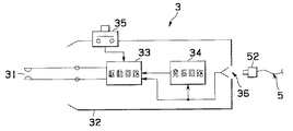
前記アームスタンド24には例えば手術装置である図3に示す処置部位の出血に対し高周波電流を流すことによって凝固・止血及び切開を行える処置電極部31を備えた焼灼装置3に電力を供給する、破線に示す前記支柱23内に設けられて電圧変換を行う電源回路41と、前記顕微鏡部21の側部に配置された前記焼灼装置3との電気的接続部42と、この電気的接続部42と前記電源回路41とを電気的に接続する図示しない信号線等に並走する接続線である接続ケーブル43とを備えた電源供給部4が設けられている。
【0026】
なお、符号25は電源回路41から延出して手術室内の図示しない商用電源のコンセントに接続されるプラグ26を備えたACコードである。
【0027】
図2に示すように前記電源供給部4の電源回路41は、前記プラグ26を介して例えば100ボルトや240ボルト等の商用電源に接続される一次回路44と、この一次回路44と絶縁トランス45を介して結合される二次回路である手術顕微鏡用電源に変換する顕微鏡用電源回路46及び手術装置用電源である例えばDC12ボルトやDC48ボルト等の低電圧源に変換する装置用絶縁トランス48及び整流回路49を備えた手術装置用電源回路47とで主に構成されている。そして、この手術装置用電源回路47から前記電気的接続部42に向かって前記接続ケーブル43が延出している。
【0028】
一方、前記電気的接続部42は、前記接続ケーブル43の端部が電気的に接続される例えばメス型コネクタ42aであり、このメス型コネクタ42aに前記電気ケーブル5の一端部に設けた第1オス型コネクタ51が着脱自在に接続されるようになっている。
【0029】
図3に示すように処置電極31を先端に備えた焼灼装置3の操作部を兼ねる把持部32内には処置電極31を駆動する駆動回路33と、数100キロヘルツないし数メガヘルツの高周波信号を生成する発振回路34とが設けられている。
【0030】
また、前記把持部32の例えば側周部には前記駆動回路33のON/OFF制御を行う操作スイッチ35が設けられ、基端面部には前記電気ケーブル5の他端部に設けられている第2オス型コネクタ52が電気的に接続されるメス型コネクタ36が配設されている。
【0031】
上述のように構成した手術システムの作用を説明する。
まず、処置を行う手術装置として焼灼装置3を用意し、電気ケーブル5に設けられている第1オス型コネクタ51を顕微鏡部21のメス型コネクタ42aに接続する一方、電気ケーブル5の他端部に設けられている第2オス型コネクタ52を焼灼装置3のメス型コネクタ36に接続する。
【0032】
次に、術者は、焼灼装置3の操作スイッチ35をON状態に操作する。すると、前記電源供給部4に設けられている手術装置用電源回路47で変換された低電圧源がこの焼灼装置3内の駆動回路33及び発振回路34に供給される。
【0033】
前記焼灼装置3に電力が供給されることにより、発振回路34では高周波信号が発生する。そして、この発振回路34で発生した高周波信号は、前記駆動回路33に供給され、この駆動回路33で増幅された後、処置電極31に伝達される。
【0034】
このことにより、処置電極31では高周波信号と生体組織の抵抗値によって決まるジュール熱によって、生体組織を蒸散させ、術者の所望する組織の凝固・止血又は切開等の処置を行える。
【0035】
なお、本実施形態においては手術装置を焼灼装置としたが、手術用顕微鏡とともにシステムを構成する手術装置としては焼灼装置に限定されるものではなく、超音波メスなどの電気的に駆動する手術装置であってもよい。また、電気ケーブルに例えばコイル状にカールしたカール部を設けるようにしてもよい。さらに、本実施形態においては、焼灼装置3に電源を供給する手術装置用電源回路47を手術用顕微鏡2の支柱23に内蔵する構成を示しているが、前記手術装置用電源回路47を手術室内に配置する電源装置として設置し、顕微鏡部21に電気的接続部42を設ける構成にしてもよい。このとき、前記手術室内に配置された電源装置内の手術装置用電源回路47と前記電気的接続部42とを接続ケーブル43で接続する構成とし、この接続ケーブル43を手術用顕微鏡2の支柱23及び支持アーム部22内に挿通配置する。また、接続ケーブル43は手術用顕微鏡2の外表面を沿わせる構造でもよい。
【0036】
このように、手術システムで使用される手術装置の電源供給部を、観察・撮像装置である手術用顕微鏡に一体に設け、この電源供給部の電気的接続部を手術用顕微鏡の中で最も患者の近くに位置する顕微鏡部に設けたことにより、手術装置に着脱自在に接続される電気ケーブルを患者の近傍に位置する電気的接続部に電気的に接続して、手術空間を十分に確保することができるとともに、術者は、手術ベッド上や床上を這う電気ケーブルに注意を払うことなく、集中して顕微鏡を観察しながらの処置を行うことができる。
【0037】
このことによって、手術装置から延出する電気ケーブルが手術ベッド上や手術室の床上を這うことがなくなって、良好な作業空間を得られる。
【0038】
また、商用電源を手術装置用電源回路によって低電圧源に変換するまでの間に、絶縁トランスを二重に設けたことによって、商用電源と患者とを完全に分離して患者の電気的な安全を確保することができる。
【0039】
図4ないし図6は本発明の第2実施形態に係り、図4は手術システムの他の構成例を示す図、図5は超音波メスの構成を説明する図、図6はTVカメラヘッド及びTVコントローラの構成を説明する図である。
【0040】
図4に示すように本実施形態の手術システム1Aは、処置部位である腹腔内を観察しながら処置を行う手術システムの構成を示すものであり、患者の腹壁には処置部位を観察する光学視管6を腹腔内に導く第1トラカール11と、処置部位に対する処置を行う手術装置である例えば超音波メス7を腹腔内に導く第2トラカール12とが穿刺されている。
【0041】
前記第1トラカール11を介して腹腔内に導かれる光学視管6は、細長な挿入部61と、この挿入部61の基端に設けた操作部を兼ねる把持部62とで主に構成されている。そして、前記挿入部内には照明光を供給する照明光学系及び処置部位の観察像を得る観察光学系が挿通配置されており、挿入部先端面61aには照明光が出射される図示しない照明光出射端及び観察用レンズが配置されている。
【0042】
また、前記把持部62の側部にはライトガイド口金63が設けられており、このライトガイド口金63に照明光を供給する光源装置13に接続された照明光伝送用のライトガイドケーブル14を接続することによって、前記光源装置13で発生された照明光がライトガイドケーブル14及び光学視管6に配置されている照明光学系を介して先端部まで伝送されて、照明光出射端から観察部位に向かって出射される。
【0043】
さらに、前記把持部62の基端部には接眼部64が設けられており、この接眼部64にはカメラアダプタ65を介して前記観察光学系でとらえた光学像を画像信号に光電変換する固体撮像素子(図6符号66a参照)を内蔵した撮像部となるTVカメラヘッド66が着脱自在に接続されるようになっている。
【0044】
前記TVカメラヘッド66からは制御装置であるTVコントローラ15に接続されるTVケーブル67が延出しており、このTVケーブル67を介して前記固体撮像素子66aで光電変換された画像信号がTVコントローラ15に設けられている信号処理回路(図6符号16)に出力されるようになっている。
【0045】
なお、前記信号処理回路16では前記画像信号を映像信号に生成し、この映像信号をモニタ17に出力する。このことによって、モニタ17の画面上に処置部位の観察画像が表示される。
【0046】
一方、前記超音波メス7は、把持部を兼ねる操作部71の例えば基端に、電気ケーブル5Aの一端部に設けたオス型コネクタ(図5符号53参照)が着脱自在に接続されており、この電気ケーブル5Aの他端部に設けられているオス型コネクタ54(図6符号54参照)が前記TVカメラヘッド66に着脱自在に接続されるようになっている。つまり、前記超音波メス7には前記TVカメラヘッド66及び電気ケーブル5Aを介してTVコントローラ15から低電圧源が供給されるようになっている。
【0047】
図5に示すように超音波メス7は、操作部71には超音波振動を発生する超音波振動子72と、この超音波振動子72を駆動する駆動回路73と、この駆動回路73をON/OFF制御する操作スイッチ74と、前記電気ケーブル5Aのオス型コネクタ53が着脱自在に接続されるメス型コネクタ75とを具備している。そして、前記超音波振動子72からの超音波振動は、前記操作部71の先端側に延出する超音波プローブ76によってメス先端部77に伝達されるようになっている。
【0048】
図6に示すように前記TVコントローラ15にはプラグ69aを備えたACコード69によって例えば100ボルトや240ボルト等の商用電源に接続される電源供給部4を構成する電源回路41Aが設けられている。
【0049】
この電源回路41Aは、商用電源に接続された一次回路44と、この一次回路44と絶縁トランス45を介して結合される二次回路である信号処理回路16及び手術装置用電源である例えばDC12ボルトやDC48ボルト等の低電圧源に変換する手術装置用電源回路47とで主に構成されている。
【0050】
一方、前記TVカメラヘッド66内には固体撮像素子66aが内蔵されており、TVケーブル67内を挿通する信号ケーブル67aによって、前記TVコントローラ15内の信号処理回路16と電気的に接続されている。
【0051】
また、このTVカメラヘッド66の例えば側面部には前記超音波メス7に一端部が接続される電気ケーブル5Aの他端部に設けられているオス型コネクタ54が着脱自在に接続される電気的接続部を構成するメス型コネクタ66bが設けられている。そして、このメス型コネクタ66bには前記手術装置用電源回路47から延出して前記TVケーブル67内を信号線等に並走して挿通する接続線である接続ケーブル68の一端部が接続されている。つまり、本実施形態においては電源供給部4がTVコントローラ15内に設けた電源回路41Aと電気的接続部であるTVカメラヘッド66に設けたメス型コネクタ66bと接続ケーブル68とで構成されている。
【0052】
その他の構成は前記第1実施形態と同様であり同部材には同符合を付して説明を省略する。
【0053】
上述のように構成した手術システムの作用を説明する。
処置を行う手術装置である超音波メス7のメス型コネクタ75及びTVカメラヘッド66のメス型コネクタ66bに、それぞれ電気ケーブル5Aに設けられているオス型コネクタ53,54を接続しておく。
【0054】
この状態で術者が超音波メス7の操作スイッチ74をON状態に操作すると、前記手術装置用電源回路47で変換された低電圧源がこの超音波メス7内の駆動回路73に供給され、この駆動回路73から超音波振動子72に駆動信号が出力される。すると、前記超音波振動子72で超音波振動を発生し、この超音波振動が超音波プローブ76によってメス先端部77に伝達されて、術者の所望する組織の切開等の処置を行える。
【0055】
なお、本実施形態においては手術装置を超音波メスとしたが、トラカール12を介して腹腔に導かれるシステムを構成する手術装置は超音波メスに限定されるものではなく、電気焼灼装置などの電気的に駆動する手術装置であってもよい。
【0056】
このように、手術システムで使用される手術装置の電源供給部を、観察・撮像装置を構成するTVカメラヘッド及びTVコントローラに一体に設け、この電源供給部の電気的接続部を最も患者の近くに位置するTVカメラヘッドに設けたことにより、手術装置に着脱自在に接続される電気ケーブルを患者の近傍に位置する電気的接続部に電気的に接続して、手術空間を十分に確保することができるとともに、術者は、手術ベッド上や床上を這う電気ケーブルに注意を払うことなく、集中して顕微鏡を観察しながらの処置を行うことができる。その他の作用及び効果は前記第1実施形態と同様である。
【0057】
このことにより、超音波メスに接続される電気ケーブルがTVケーブルやライトガイド等に絡まって光学視管及び超音波メスの操作性を損なうことが防止される。
【0058】
図7及び図8は本発明の第3実施形態に係り、図7は手術システムの別の構成例を示す図、図8は電気メスの構成を説明する図である。
【0059】
図7に示すように本実施形態の手術システム1Bは、処置部位である腹腔内を観察しながら処置を行う手術システムの他の構成を示すものであり、患者の腹腔内には処置部位を観察する電子内視鏡8が挿入される。そして、この電子内視鏡8の処置具チャンネル(不図示)を介して処置部位に対する処置を行う手術装置である例えば電気メスの1つである高周波スネア9が挿入されるようになっている。
【0060】
前記電子内視鏡8は、腹腔内に挿入される細長で柔軟な挿入部81と、この挿入部81の基端に設けた把持部を兼ねる操作部82と、この操作部82の側部から延出するユニバーサルコード83とで主に構成されている。
【0061】
前記挿入部81の先端面には観察光学系を構成する光学レンズ84が配置されており、この光学レンズ84の結像位置には観察像を画像信号に光電変換する撮像部である固体撮像素子85が配設されている。
【0062】
また、前記ユニバーサルコード83の基端部にはユニバーサルコード83及び操作部82,挿入部81内を挿通するライトガイド(不図示)を介して照明光を供給する光源装置13に接続される光源コネクタ86が設けられている。この光源コネクタ86の側部からは前記固体撮像素子85で光電変換した画像信号を映像信号に生成する信号処理回路16を設けた制御装置であるビデオプロセッサ18に接続されるビデオケーブル19が図示しないコネクタによって着脱自在に接続されている。なお、この光源コネクタ86の前記コネクタは洗滌時に水密性が保たれるよう、防水キャップが付けられる構造となっている。
【0063】
つまり、前記固体撮像素子85で光電変換された画像信号は、挿入部81,操作部82,ユニバーサルコード83,ビデオケーブル19内を挿通する信号伝送ケーブル87によって前記信号処理回路16に伝送されるようになっている。なお、符号88は前記処置具チャンネルに連通する処置具挿通口であり、この処置具挿通口88から前記高周波スネア9が挿入される。
【0064】
前記ビデオプロセッサ18にはプラグ80aを備えたACコード80によって例えば100ボルトや240ボルト等の商用電源に接続される電源供給部4を構成する電源回路41Bが設けられている。そして、この電源回路41Bには信号処理回路16及び手術装置用電源である例えばDC12ボルトやDC48ボルト等の低電圧源に変換する手術装置用電源回路47とが設けられている。
【0065】
前記手術装置用電源回路47からは接続線である接続ケーブル89が信号線等に並走して延出しており、この接続ケーブル89は前記ビデオケーブル19,光源コネクタ86及びユニバーサルコード83内を挿通して撮像部近傍であって患者体外近傍に位置する操作部82に設けられている電気的接続部を構成するメス型コネクタ82aに電気的に接続されている。
【0066】
つまり、本実施形態においては電源供給部4がビデオプロセッサ18内に設けた電源回路41Bと電気的接続部である電子内視鏡8の操作部82に設けたメス型コネクタ82aと接続ケーブル89とで構成されている。
【0067】
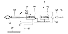
一方、高周波スネア9は、操作部を兼ねる把持部91と、可撓性を有するスネアガイド92及び処置部電極となるスネアループ93とで主に構成されている。なお、符号5Bは電子内視鏡8と高周波スネア9とを電気的に接続して前記手術装置用電源回路47で変換された低電圧源を高周波スネア9に供給する電気ケーブルであり、この電気ケーブル5Bの端部には前記メス型コネクタ82a及び後述するメス型コネクタ99に着脱自在に接続されるオス型コネクタ55,56が設けられている。符号98は患者に接触配置される患者電極となるスネアループ93に対する対極板であり、電極コード97によって把持部91に接続されている。この電極コード97は、スネアガイド92などに接触した際の電気的安全性を向上させるため、電気的シールドを施すとともに、絶縁を強化した構造となっている。
【0068】
図8に示すように高周波スネア9の把持部91にはスネアループ93を駆動する駆動回路94と、数100キロヘルツないし数メガヘルツの高周波信号を生成する発振回路95と、前記駆動回路94をON/OFF制御する操作スイッチ96と、前記電気ケーブル5Bのオス型コネクタ56が着脱自在に接続されるメス型コネクタ99とが設けられている。なお、図に示すように前記対極板98から延出している電極コード97は駆動回路94に電気的に接続されている。
【0069】
上述のように構成した手術システムの作用を説明する。
処置を行う手術装置である高周波スネア9のメス型コネクタ99及び電子内視鏡8の操作部82に設けられているメス型コネクタ82aに、それぞれ電気ケーブル5Bのオス型コネクタ55,56を接続しておく。
【0070】
この状態で術者が高周波スネア9の操作スイッチ96をON状態に操作すると、前記手術装置用電源回路47で変換された低電圧源が高周波スネア9の駆動回路94と発振回路95とに供給される。
【0071】
前記高周波スネア9に電力が供給されることにより、発振回路95では高周波信号が発生する。そして、この発振回路95で発生した高周波信号は、前記駆動回路94に供給され、この駆動回路94で増幅された後、スネアループ93に伝達される。
【0072】
このことにより、スネアループ93と対極板98との間で、この高周波信号と生体組織の抵抗値によって決まるジュール熱が発生し、生体組織を蒸散して、組織の切開が行われる。
【0073】
なお、本実施形態においては手術装置を高周波スネアとしたが、内視鏡の処置具チャンネルに挿通されてシステムを構成する手術装置としては高周波スネアに限定されるものではなく、超音波メスなどの電気的に駆動する手術装置であってもよい。
【0074】
このように、手術システムで使用される手術装置の電源供給部を、観察・撮像装置を構成するビデオプロセッサ及びこのビデオプロセッサに接続されるビデオケーブル及び電子内視鏡に設け、この電源供給部の電気的接続部を患者の近くに位置する操作部に設けたことにより、手術装置に着脱自在に接続される電気ケーブルを患者の近傍に位置する電気的接続部に電気的に接続して、手術空間を十分に確保することができる。その他の作用及び効果は上述した実施形態と同様である。
【0075】
このことにより、高周波スネアに接続される電気ケーブルが内視鏡のユニバーサルコード等に絡まって電子内視鏡及び高周波スネアの操作性を損なうことが防止される。
【0076】
なお、本発明は、以上述べた実施形態のみに限定されるものではなく、発明の要旨を逸脱しない範囲で種々変形実施可能である。
【0077】
[付記]
以上詳述したような本発明の上記実施形態によれば、以下の如き構成を得ることができる。
【0078】
(1)対象部位を観察あるいは撮像するための観察・撮像部を有する観察・撮像装置と、
前記対象部位に対する処置を施す少なくとも1つの電動駆動される手術装置と、
前記観察・撮像部近傍、患者体外近傍に配置され、前記手術装置に電源を供給するための電気的接続部と、
前記観察・撮像部と前記観察・撮像装置本体とを接続する信号線に並走し、前記電気的接続部に接続される接続線と、
を具備する手術システム。
【0079】
(2)前記電気的接続部は、対象部位の観察を行う観察・撮像装置に設けられている付記1記載の手術システム。
【0080】
(3)前記観察・撮像装置又は前記手術装置の少なくとも一方に、電圧変換を行う電源回路を設けた付記2記載の手術システム。
【0081】
(4)前記観察・撮像装置の一部に、前記手術装置との電気的接続部を設けた付記2記載の手術システム。
【0082】
(5)前記電気的接続部を、前記観察・撮像装置の手術を受ける患者近くに配置した付記4記載の手術システム。
【0083】
(6)前記観察・撮像装置は、手術用顕微鏡である付記1記載の手術システム。
(7)前記観察・撮像装置は、TVカメラである付記1記載の手術システム。
【0084】
(8)前記観察・撮像装置は、電子内視鏡である付記1記載の手術システム。
【0085】
(9)対象部位を観察する顕微鏡部と、
この顕微鏡部を支持するアームスタンドとで構成される手術用顕微鏡において、
前記顕微鏡部に、外部機器に電源を出力することを可能にする電気的接続部を設けた手術用顕微鏡。
【0086】
(10)前記アームスタンド内に、商用電源の電圧を所定の電圧に変換する電源回路を設け、
この電源回路と前記電気的接続部とを前記アームスタンド内に挿通配置された接続供給手段により電気的に接続した付記9記載の手術用顕微鏡。
【0087】
(11)撮像手段を備えたTVカメラヘッドと、
前記撮像手段から出力された画像信号が入力され、この画像信号を映像信号に生成して観察手段に出力する信号処理回路を備えたコントローラとを具備する医療用TVカメラにおいて、
前記医療用TVカメラのカメラヘッド部に、外部機器に電源を出力することを可能にする電気的接続部を設けた医療用TVカメラ。
【0088】
(12)前記コントローラ内に、商用電源の電圧を所定の電圧に変換する電源回路を設け、
この電源回路と前記電気的接続部とを、前記カメラヘッド部と前記コントローラとを接続するコード内に配設した、接続供給手段によって電気的に接続した付記11記載の医療用TVカメラ。
【0089】
(13)体腔内に挿入されるの挿入部の先端部に設けた固体撮像素子と、
前記挿入部の基端に配設された把持部とを具備した電子内視鏡において、
前記把持部に外部機器に電源を出力することを可能にする電気的接続部を設けた電子内視鏡。
【0090】
(14)対象部位を観察あるいは撮像するための観察・撮像部を有する治療用観察・撮像装置であって、
前記対象部位に対する処置を施す少なくとも1つの電動駆動される手術装置に電源を供給するために、前記観察・撮像部近傍、患者体外近傍に配置される電気的接続部と、
前記観察・撮像部と前記観察・撮像装置本体とを接続する信号線に並走し、前記電気的接続部に接続される接続線と、
を具備する治療用観察・撮像装置。
【0091】
【発明の効果】
以上説明したように本発明によれば、手術室内の空間を有効利用して、術者に作業生が良好で十分な作業空間の提供を図れる手術システムを提供することができる。
【図面の簡単な説明】
【図1】図1ないし図3は本発明の第1実施形態に係り、図1は手術システムの1例を示す図
【図2】手術顕微鏡に設けた手術装置に電源を供給する電源供給部を説明する図
【図3】焼灼装置の1構成を説明する図
【図4】図4ないし図6は本発明の第2実施形態に係り、図4は手術システムの他の構成例を示す図
【図5】超音波メスの構成を説明する図
【図6】TVカメラヘッド及びTVコントローラの構成を説明する図
【図7】図7及び図8は本発明の第3実施形態に係り、図7は手術システムの別の構成例を示す図
【図8】電気メスの構成を説明する図
【図9】従来の超音波手術装置の構成例を示す図
【図10】マイクロサージャリーによる脳外科手術装置の構成例を示す図
【図11】腹腔鏡と手術装置とで構成した医療システムを示す図
【符号の説明】
1…手術システム
2…手術用顕微鏡
3…焼灼装置
4…電源供給部
5…電気ケーブル
41…電源回路
42…電気的接続部
43…接続ケーブル[0001]
BACKGROUND OF THE INVENTION
The present invention relates to a surgical system that performs biopsy or treatment of a target region using an electrically driven surgical device while observing or imaging the target region with an observation / imaging device. To Related.
[0002]
[Prior art]
In recent years, in the medical field, a surgical system configured by combining an observation / imaging device and a surgical device in accordance with a surgical site or procedure has been used.
[0003]
As this observation / imaging device, an insertion portion that is inserted into a body cavity from the oral cavity or anus is a flexible endoscope, or a laparoscope whose insertion portion is disposed in the abdominal cavity through a trocar punctured in the abdominal wall ( Optical microscopes) and surgical microscopes that can observe enlarged nerves and blood vessels.
[0004]
The state of the observation site captured by these endoscopes or surgical microscopes can be observed directly by visual observation, or an optical image captured by these endoscopes or surgical microscopes can be displayed on, for example, a monitor screen through a control device that generates a video signal. It was supposed to be displayed and observed.
[0005]
On the other hand, as surgical devices, there are surgical devices driven by a power source in addition to surgical instruments such as grasping forceps and a scalpel. As a surgical device that is electrically driven by power supplied from this power source, for example, a treatment tool is vibrated using ultrasonic vibration, and a living tissue as a target site is incised or coagulated by vibration of the treatment tool, Ultrasonic surgical device that pulverizes and sucks, incision and coagulation action on living tissue that is the target site by thermal action by high frequency power, power treatment tool that finely pulverizes biological tissue with rotational force, etc. is there.
[0006]
In addition, there is an ultrasonic trocar that is punctured in a body wall to guide these medical devices into a body cavity, and the trocar is connected to a power source to vibrate ultrasonically so that the puncture can be easily performed.
[0007]
For example, as a general surgical apparatus, Japanese Patent Laid-Open No. 9-299381 discloses an example of an ultrasonic surgical apparatus. As shown in the diagram of the configuration example of the conventional ultrasonic surgical apparatus in FIG. 9, the ultrasonic surgical apparatus includes a handpiece including a probe that transmits ultrasonic vibration from an ultrasonic transducer (not shown) to the
[0008]
The electrosurgical device is also composed of a hand piece that gives energy to the treatment site and a control device that includes a circuit unit that generates this energy, as in the case of the ultrasonic surgical device. The handpiece and the control device are electrically connected by an electric cable.
[0009]
As a medical system, in the field of neurosurgery, there is a microsurgery in which surgery is performed under magnified observation of fine nerves and blood vessels. As shown in the diagram of the configuration example of the brain surgery apparatus using the microsurgery of FIG. 10, the
[0010]
The
[0011]
In addition, as shown in the medical system diagram of the laparoscope and the surgical apparatus in FIG. 11, when examining and treating the abdominal cavity with the
[0012]
The treatment site is illuminated by illumination light supplied from the
[0013]
Then, an observation image of the treatment site illuminated by the illumination light is picked up by the
[0014]
While viewing the observation image displayed on the
[0015]
On the other hand, for example, an electric knife which is a
[0016]
Further, as an example of a medical system using a flexible endoscope, Japanese Patent Laid-Open No. 4-146743 discloses a high-frequency snare for excising a lesion by a high-frequency snare as an electric knife and a biopsy method using the same. ing.
[0017]
[Problems to be solved by the invention]
However, the above-described electrically driven surgical device configured as a surgical system and a high-frequency power supply device, an optical visual tube, a TV camera, a control device, and a light source device are connected via an electric cable, a camera cable, and a light guide cable. Therefore, these cables may be stretched or entangled during the operation, and the operability may be impaired. In addition, since the surgeon was paying attention so as not to get caught in these cables, it was difficult not only to concentrate on the surgery, but also the problem that the operator's movement space and surgical space were limited. there were.
[0018]
The present invention has been made in view of the above circumstances, and a surgical system capable of effectively utilizing the space in the operating room and providing a sufficient work space to the operator with good work life. The The purpose is to provide.
[0019]
[Means for Solving the Problems]
The surgical system according to the present invention comprises: Electric drive means for generating treatment energy by electric drive so as to be able to treat the target site; , A treatment section provided to be able to transmit the treatment energy to the target site; , An electric power input unit provided so as to be able to input electric power to be supplied to the electric driving means so that the electric driving means can be driven. A surgical device; An observation apparatus having an observation tool that can be placed at a desired position so that the target site can be observed; , A power supply circuit unit that is provided in the observation device and generates electric power for driving the electric driving means; , A power output unit provided in the observation tool and provided so as to be able to output the power generated by the power supply circuit unit; , A cable provided so that the power output unit and the power input unit can be electrically connected; It has.
[0021]
According to the surgical system of the present invention, the necessary power can be secured from a location close to the target site, so the cable for supplying power does not get in the way. .
[0022]
DETAILED DESCRIPTION OF THE INVENTION
Embodiments of the present invention will be described below with reference to the drawings.
1 to 3 relate to a first embodiment of the present invention, FIG. 1 is a diagram showing an example of a surgical system, and FIG. 2 is a diagram for explaining a power supply unit that supplies power to a surgical apparatus provided in a surgical microscope. FIG. 3 is a diagram for explaining one configuration of the ablation apparatus.
[0023]
As shown in FIG. 1, the
[0024]
The
[0025]
Electric power is supplied to the arm stand 24 to the
[0026]
[0027]
As shown in FIG. 2, the
[0028]
On the other hand, the
[0029]
As shown in FIG. 3, a driving
[0030]
In addition, an
[0031]
The operation of the operation system configured as described above will be described.
First, a
[0032]
Next, the surgeon operates the
[0033]
When electric power is supplied to the
[0034]
Thus, the
[0035]
In this embodiment, the surgical apparatus is an ablation device. However, the surgical apparatus that constitutes the system together with the surgical microscope is not limited to the cauterization apparatus, and is an electrically driven surgical apparatus such as an ultrasonic scalpel. It may be. Further, the electric cable may be provided with a curled portion curled in a coil shape, for example. Furthermore, in the present embodiment, a configuration is shown in which a surgical device
[0036]
In this way, the power supply unit of the surgical device used in the surgical system is provided integrally with the surgical microscope, which is an observation / imaging device, and the electrical connection part of this power supply unit is the most patient among the surgical microscopes. By providing it in the microscope section located near the surgical device, the electrical cable that is detachably connected to the surgical apparatus is electrically connected to the electrical connection section located in the vicinity of the patient, so that a sufficient surgical space is secured. In addition, the surgeon can perform the procedure while observing the microscope in a concentrated manner without paying attention to the electric cable that crawls on the surgical bed or on the floor.
[0037]
As a result, the electric cable extending from the surgical apparatus does not crawl on the surgical bed or the floor of the operating room, and a good working space can be obtained.
[0038]
In addition, by providing double insulation transformers before the commercial power supply is converted to a low voltage source by the power supply circuit for the surgical device, the commercial power supply and the patient are completely separated, and the patient's electrical safety Can be secured.
[0039]
4 to 6 relate to the second embodiment of the present invention, FIG. 4 is a diagram showing another configuration example of the surgical system, FIG. 5 is a diagram for explaining the configuration of the ultrasonic knife, and FIG. It is a figure explaining the structure of TV controller.
[0040]
As shown in FIG. 4, the surgical system 1A of the present embodiment shows a configuration of a surgical system that performs a treatment while observing the abdominal cavity, which is a treatment site. A first trocar 11 that guides the tube 6 into the abdominal cavity and a
[0041]
The optical viewing tube 6 guided into the abdominal cavity through the first trocar 11 is mainly composed of a long and
[0042]
Further, a
[0043]
Further, an
[0044]
A
[0045]
The
[0046]
On the other hand, the
[0047]
As shown in FIG. 5, the
[0048]
As shown in FIG. 6, the
[0049]
The
[0050]
On the other hand, a solid-
[0051]
Further, for example, a side surface portion of the
[0052]
Other configurations are the same as those of the first embodiment, and the same members are denoted by the same reference numerals and description thereof is omitted.
[0053]
The operation of the operation system configured as described above will be described.
[0054]
When the operator operates the operation switch 74 of the
[0055]
In this embodiment, the surgical apparatus is an ultrasonic knife. However, the surgical apparatus constituting the system guided to the abdominal cavity via the
[0056]
As described above, the power supply unit of the surgical device used in the surgical system is provided integrally with the TV camera head and the TV controller constituting the observation / imaging device, and the electrical connection unit of the power supply unit is closest to the patient. By providing the TV camera head located in the position, the electrical cable that is detachably connected to the surgical device can be electrically connected to the electrical connection located in the vicinity of the patient to ensure a sufficient surgical space. In addition, the surgeon can perform a procedure while observing the microscope in a concentrated manner without paying attention to the electric cable that crawls on the surgical bed or on the floor. Other operations and effects are the same as those in the first embodiment.
[0057]
This prevents the electric cable connected to the ultrasonic knife from being entangled with the TV cable, the light guide, etc. and impairing the operability of the optical visual tube and the ultrasonic knife.
[0058]
7 and 8 relate to the third embodiment of the present invention, FIG. 7 is a diagram showing another configuration example of the surgical system, and FIG. 8 is a diagram for explaining the configuration of the electric knife.
[0059]
As shown in FIG. 7, the
[0060]
The
[0061]
An
[0062]
A light source connector connected to a
[0063]
That is, the image signal photoelectrically converted by the solid-
[0064]
The
[0065]
A
[0066]
In other words, in this embodiment, the power supply unit 4 is connected to the
[0067]
On the other hand, the high-frequency snare 9 is mainly composed of a
[0068]
As shown in FIG. 8, the
[0069]
The operation of the operation system configured as described above will be described.
The
[0070]
When the surgeon operates the operation switch 96 of the high frequency snare 9 in the ON state in this state, the low voltage source converted by the surgical device
[0071]
When power is supplied to the high frequency snare 9, a high frequency signal is generated in the oscillation circuit 95. The high frequency signal generated by the oscillation circuit 95 is supplied to the
[0072]
As a result, Joule heat determined by the high-frequency signal and the resistance value of the living tissue is generated between the
[0073]
In the present embodiment, the surgical device is a high-frequency snare, but the surgical device that is inserted into the endoscope treatment instrument channel to constitute the system is not limited to the high-frequency snare, such as an ultrasonic scalpel. It may be a surgical device that is electrically driven.
[0074]
As described above, the power supply unit of the surgical device used in the surgical system is provided in the video processor constituting the observation / imaging device, the video cable connected to the video processor, and the electronic endoscope. By providing the electrical connection part in the operation part located near the patient, the electrical cable that is detachably connected to the surgical device is electrically connected to the electrical connection part located in the vicinity of the patient, and surgery is performed. Sufficient space can be secured. Other operations and effects are the same as those of the above-described embodiment.
[0075]
This prevents the electric cable connected to the high-frequency snare from being entangled with the universal cord of the endoscope and the operability of the electronic endoscope and the high-frequency snare.
[0076]
It should be noted that the present invention is not limited to the embodiments described above, and various modifications can be made without departing from the spirit of the invention.
[0077]
[Appendix]
According to the embodiment of the present invention as described above in detail, the following configuration can be obtained.
[0078]
(1) an observation / imaging device having an observation / imaging unit for observing or imaging a target part;
At least one electrically driven surgical device for performing treatment on the target site;
Near the observation / imaging unit, near the patient's body, and an electrical connection unit for supplying power to the surgical device;
A parallel connection with the signal line connecting the observation / imaging unit and the observation / imaging device body, and a connection line connected to the electrical connection unit,
A surgical system comprising:
[0079]
(2) The surgical operation system according to
[0080]
(3) The surgical system according to
[0081]
(4) The surgical operation system according to
[0082]
(5) The surgical operation system according to appendix 4, wherein the electrical connection portion is arranged near a patient who undergoes surgery of the observation / imaging device.
[0083]
(6) The surgical operation system according to
(7) The surgical operation system according to
[0084]
(8) The surgical operation system according to
[0085]
(9) a microscope unit for observing the target site;
In a surgical microscope composed of an arm stand that supports this microscope section,
A surgical microscope provided with an electrical connection section that enables a power source to be output to an external device in the microscope section.
[0086]
(10) In the arm stand, a power supply circuit for converting the voltage of the commercial power supply into a predetermined voltage is provided,
The surgical microscope according to appendix 9, wherein the power supply circuit and the electrical connection portion are electrically connected by connection supply means inserted and arranged in the arm stand.
[0087]
(11) a TV camera head provided with imaging means;
In a medical TV camera comprising a controller having a signal processing circuit that receives an image signal output from the imaging unit, generates the image signal as a video signal, and outputs the image signal to an observation unit.
A medical TV camera in which an electrical connection portion that enables power to be output to an external device is provided in a camera head portion of the medical TV camera.
[0088]
(12) Provided in the controller is a power supply circuit for converting a commercial power supply voltage into a predetermined voltage;
The medical TV camera according to supplementary note 11, wherein the power supply circuit and the electrical connection portion are electrically connected by a connection supply means disposed in a cord connecting the camera head portion and the controller.
[0089]
(13) a solid-state imaging device provided at a distal end portion of an insertion portion to be inserted into a body cavity;
In an electronic endoscope comprising a gripping portion disposed at a proximal end of the insertion portion,
An electronic endoscope provided with an electrical connection portion that enables a power source to be output to an external device on the grip portion.
[0090]
(14) A therapeutic observation / imaging apparatus having an observation / imaging unit for observing or imaging a target region,
In order to supply power to at least one electrically driven surgical device that performs treatment on the target region, an electrical connection unit disposed in the vicinity of the observation / imaging unit, outside the patient body, and
A parallel connection with the signal line connecting the observation / imaging unit and the observation / imaging device body, and a connection line connected to the electrical connection unit,
A therapeutic observation / imaging apparatus comprising:
[0091]
【The invention's effect】
As described above, according to the present invention, a surgical system that can effectively use the space in the operating room and provide a sufficient work space for the operator with good work life. The To provide Can .
[Brief description of the drawings]
FIG. 1 to FIG. 3 relate to a first embodiment of the present invention, and FIG. 1 is a diagram showing an example of a surgical system.
FIG. 2 is a diagram illustrating a power supply unit that supplies power to a surgical apparatus provided in a surgical microscope.
FIG. 3 is a diagram for explaining one configuration of a shochu apparatus
FIGS. 4 to 6 relate to a second embodiment of the present invention, and FIG. 4 is a diagram showing another configuration example of the surgical system.
FIG. 5 is a diagram for explaining the configuration of an ultrasonic knife.
FIG. 6 is a diagram illustrating the configuration of a TV camera head and a TV controller.
FIGS. 7 and 8 relate to a third embodiment of the present invention, and FIG. 7 is a diagram showing another configuration example of a surgical system.
FIG. 8 is a diagram illustrating the configuration of an electric knife
FIG. 9 is a diagram illustrating a configuration example of a conventional ultrasonic surgical apparatus.
FIG. 10 is a diagram showing a configuration example of a brain surgery apparatus using microsurgery.
FIG. 11 is a diagram showing a medical system composed of a laparoscope and a surgical apparatus.
[Explanation of symbols]
1 ... Surgery system
2. Surgery microscope
3 ... Shochu device
4 ... Power supply unit
5 ... Electric cable
41 ... Power supply circuit
42. Electrical connection
43 ... Connection cable
Claims (1)
前記処置エネルギーを前記対象部位に伝達可能となるように設けられた処置部と、
前記電動駆動手段を駆動可能となるように、前記電動駆動手段に供給する電力を入力可能となるように設けられた電力入力部と、
を備えた手術装置と、
前記対象部位を観察可能となるように、所望の位置に配置可能な観察具を有する観察装置と、
前記観察装置に設けられ、前記電動駆動手段を駆動させるための電力を生成する電源回路部と、
前記観察具に設けられ、前記電源回路部によって生成された電力を出力可能となるように設けられた電力出力部と、
前記電力出力部と前記電力入力部を電気的に接続可能となるように設けられたケーブルと、
を具備することを特徴とする手術システム。 Electric drive means for generating treatment energy by electric drive so as to be able to treat the target site ;
A treatment section provided to be able to transmit the treatment energy to the target site ;
An electric power input unit provided so as to be able to input electric power to be supplied to the electric drive means so that the electric drive means can be driven ;
A surgical device comprising:
An observation device having an observation tool that can be placed at a desired position so that the target site can be observed ;
A power supply circuit unit that is provided in the observation device and generates electric power for driving the electric driving means ;
A power output unit provided in the observation tool and provided so as to be able to output the power generated by the power supply circuit unit ;
A cable provided so that the power output unit and the power input unit can be electrically connected ;
A surgical system comprising:
Priority Applications (1)
| Application Number | Priority Date | Filing Date | Title |
|---|---|---|---|
| JP01758899A JP3631388B2 (en) | 1999-01-26 | 1999-01-26 | Surgery system |
Applications Claiming Priority (1)
| Application Number | Priority Date | Filing Date | Title |
|---|---|---|---|
| JP01758899A JP3631388B2 (en) | 1999-01-26 | 1999-01-26 | Surgery system |
Publications (2)
| Publication Number | Publication Date |
|---|---|
| JP2000210302A JP2000210302A (en) | 2000-08-02 |
| JP3631388B2 true JP3631388B2 (en) | 2005-03-23 |
Family
ID=11948073
Family Applications (1)
| Application Number | Title | Priority Date | Filing Date |
|---|---|---|---|
| JP01758899A Expired - Fee Related JP3631388B2 (en) | 1999-01-26 | 1999-01-26 | Surgery system |
Country Status (1)
| Country | Link |
|---|---|
| JP (1) | JP3631388B2 (en) |
Families Citing this family (3)
| Publication number | Priority date | Publication date | Assignee | Title |
|---|---|---|---|---|
| JP4073249B2 (en) | 2002-05-17 | 2008-04-09 | オリンパス株式会社 | Surgery system |
| EP3323374B1 (en) | 2015-08-20 | 2020-07-08 | Sony Olympus Medical Solutions Inc. | Medical observation apparatus and medical observation system |
| CN112690903A (en) * | 2021-02-05 | 2021-04-23 | 广东欧谱曼迪科技有限公司 | Medical trolley with cable telescopic device and method thereof |
-
1999
- 1999-01-26 JP JP01758899A patent/JP3631388B2/en not_active Expired - Fee Related
Also Published As
| Publication number | Publication date |
|---|---|
| JP2000210302A (en) | 2000-08-02 |
Similar Documents
| Publication | Publication Date | Title |
|---|---|---|
| Wuchinich et al. | Endoscopic ultrasonic rotary electro-cauterizing aspirator | |
| US4998527A (en) | Endoscopic abdominal, urological, and gynecological tissue removing device | |
| US5085658A (en) | Neurosurgical pathological tissue removing device | |
| JP5567018B2 (en) | Surgical grasping device | |
| CA2273925C (en) | Mechanical and electrical endoscopic surgical instrument | |
| JP6158303B2 (en) | Surgical instrument with nerve detection function | |
| US5011483A (en) | Combined electrosurgery and laser beam delivery device | |
| US20090182332A1 (en) | In-line electrosurgical forceps | |
| US20030225332A1 (en) | Ultrasonic therapeutic apparatus | |
| US20080194999A1 (en) | Ultrasonic treatment apparatus and treatment method | |
| JP2004208922A (en) | Medical apparatus, medical manipulator and control process for medical apparatus | |
| JP2003325543A (en) | Medical operation system and medical operation apparatus thereof | |
| JP2000287987A (en) | Rechargeable medical device | |
| JPH07227394A (en) | Ultrasonic diagnostic and curing system | |
| JP3850094B2 (en) | Ultrasound diagnostic treatment system and treatment adapter | |
| JPH0994238A (en) | High-frequency treating apparatus | |
| CN113749694A (en) | Puncture biopsy and ablation system | |
| JP2000287986A (en) | Tool for surgical implement | |
| JPH11226026A (en) | Surgical surgical tools | |
| CN111556733B (en) | Systems and methods for energy delivery | |
| JP3631388B2 (en) | Surgery system | |
| JP2009153859A (en) | Endoscope drape | |
| JP2000210301A (en) | Surgical appliance | |
| JP2000254134A (en) | Medical instrument | |
| JPH07275247A (en) | Ultrasonic diagnostic and therapeutic system |
Legal Events
| Date | Code | Title | Description |
|---|---|---|---|
| A977 | Report on retrieval |
Free format text: JAPANESE INTERMEDIATE CODE: A971007 Effective date: 20040506 |
|
| A131 | Notification of reasons for refusal |
Free format text: JAPANESE INTERMEDIATE CODE: A131 Effective date: 20040511 |
|
| A521 | Request for written amendment filed |
Free format text: JAPANESE INTERMEDIATE CODE: A523 Effective date: 20040701 |
|
| TRDD | Decision of grant or rejection written | ||
| A01 | Written decision to grant a patent or to grant a registration (utility model) |
Free format text: JAPANESE INTERMEDIATE CODE: A01 Effective date: 20041207 |
|
| A61 | First payment of annual fees (during grant procedure) |
Free format text: JAPANESE INTERMEDIATE CODE: A61 Effective date: 20041216 |
|
| FPAY | Renewal fee payment (event date is renewal date of database) |
Free format text: PAYMENT UNTIL: 20081224 Year of fee payment: 4 |
|
| FPAY | Renewal fee payment (event date is renewal date of database) |
Free format text: PAYMENT UNTIL: 20081224 Year of fee payment: 4 |
|
| FPAY | Renewal fee payment (event date is renewal date of database) |
Free format text: PAYMENT UNTIL: 20091224 Year of fee payment: 5 |
|
| FPAY | Renewal fee payment (event date is renewal date of database) |
Free format text: PAYMENT UNTIL: 20101224 Year of fee payment: 6 |
|
| FPAY | Renewal fee payment (event date is renewal date of database) |
Free format text: PAYMENT UNTIL: 20111224 Year of fee payment: 7 |
|
| FPAY | Renewal fee payment (event date is renewal date of database) |
Free format text: PAYMENT UNTIL: 20111224 Year of fee payment: 7 |
|
| FPAY | Renewal fee payment (event date is renewal date of database) |
Free format text: PAYMENT UNTIL: 20121224 Year of fee payment: 8 |
|
| FPAY | Renewal fee payment (event date is renewal date of database) |
Free format text: PAYMENT UNTIL: 20131224 Year of fee payment: 9 |
|
| LAPS | Cancellation because of no payment of annual fees |