JP3626682B2 - Improved rotor for blood pump - Google Patents
Improved rotor for blood pump Download PDFInfo
- Publication number
- JP3626682B2 JP3626682B2 JP2000501343A JP2000501343A JP3626682B2 JP 3626682 B2 JP3626682 B2 JP 3626682B2 JP 2000501343 A JP2000501343 A JP 2000501343A JP 2000501343 A JP2000501343 A JP 2000501343A JP 3626682 B2 JP3626682 B2 JP 3626682B2
- Authority
- JP
- Japan
- Prior art keywords
- rotor
- pumping chamber
- rotor assembly
- pump
- axis
- Prior art date
- Legal status (The legal status is an assumption and is not a legal conclusion. Google has not performed a legal analysis and makes no representation as to the accuracy of the status listed.)
- Expired - Fee Related
Links
- 239000008280 blood Substances 0.000 title claims abstract description 33
- 210000004369 blood Anatomy 0.000 title claims abstract description 33
- 239000012530 fluid Substances 0.000 claims abstract description 95
- 238000005086 pumping Methods 0.000 claims abstract description 54
- 230000004323 axial length Effects 0.000 claims description 16
- 230000002093 peripheral effect Effects 0.000 claims description 9
- 230000032258 transport Effects 0.000 claims description 5
- 230000008878 coupling Effects 0.000 claims description 4
- 238000010168 coupling process Methods 0.000 claims description 4
- 238000005859 coupling reaction Methods 0.000 claims description 4
- 230000001066 destructive effect Effects 0.000 claims 2
- 230000009977 dual effect Effects 0.000 abstract description 3
- 230000005484 gravity Effects 0.000 description 16
- 239000000463 material Substances 0.000 description 15
- 230000000694 effects Effects 0.000 description 13
- QSHDDOUJBYECFT-UHFFFAOYSA-N mercury Chemical compound [Hg] QSHDDOUJBYECFT-UHFFFAOYSA-N 0.000 description 12
- 229910052753 mercury Inorganic materials 0.000 description 12
- 239000000306 component Substances 0.000 description 9
- 230000006870 function Effects 0.000 description 9
- 150000003839 salts Chemical class 0.000 description 6
- 239000008358 core component Substances 0.000 description 4
- 238000004804 winding Methods 0.000 description 4
- 239000004793 Polystyrene Substances 0.000 description 3
- 239000004020 conductor Substances 0.000 description 3
- 230000006378 damage Effects 0.000 description 3
- 238000010586 diagram Methods 0.000 description 3
- 238000006073 displacement reaction Methods 0.000 description 3
- 210000003746 feather Anatomy 0.000 description 3
- 238000002513 implantation Methods 0.000 description 3
- 230000001453 nonthrombogenic effect Effects 0.000 description 3
- 239000004417 polycarbonate Substances 0.000 description 3
- 229920000515 polycarbonate Polymers 0.000 description 3
- 229920002223 polystyrene Polymers 0.000 description 3
- 239000000758 substrate Substances 0.000 description 3
- 238000012546 transfer Methods 0.000 description 3
- 239000012224 working solution Substances 0.000 description 3
- 239000004925 Acrylic resin Substances 0.000 description 2
- 229920000178 Acrylic resin Polymers 0.000 description 2
- 230000002411 adverse Effects 0.000 description 2
- 210000000709 aorta Anatomy 0.000 description 2
- 239000000560 biocompatible material Substances 0.000 description 2
- 230000000747 cardiac effect Effects 0.000 description 2
- 230000008859 change Effects 0.000 description 2
- 239000011248 coating agent Substances 0.000 description 2
- 238000000576 coating method Methods 0.000 description 2
- 238000010276 construction Methods 0.000 description 2
- 238000013461 design Methods 0.000 description 2
- 230000005672 electromagnetic field Effects 0.000 description 2
- 238000004519 manufacturing process Methods 0.000 description 2
- 230000007246 mechanism Effects 0.000 description 2
- 238000012986 modification Methods 0.000 description 2
- 230000004048 modification Effects 0.000 description 2
- 210000001147 pulmonary artery Anatomy 0.000 description 2
- 230000002829 reductive effect Effects 0.000 description 2
- 238000000926 separation method Methods 0.000 description 2
- 230000003068 static effect Effects 0.000 description 2
- 231100000331 toxic Toxicity 0.000 description 2
- 230000002588 toxic effect Effects 0.000 description 2
- 239000013598 vector Substances 0.000 description 2
- 239000011800 void material Substances 0.000 description 2
- XLYOFNOQVPJJNP-UHFFFAOYSA-N water Substances O XLYOFNOQVPJJNP-UHFFFAOYSA-N 0.000 description 2
- 241001465754 Metazoa Species 0.000 description 1
- 238000009825 accumulation Methods 0.000 description 1
- NIXOWILDQLNWCW-UHFFFAOYSA-N acrylic acid group Chemical group C(C=C)(=O)O NIXOWILDQLNWCW-UHFFFAOYSA-N 0.000 description 1
- 230000001154 acute effect Effects 0.000 description 1
- 230000000712 assembly Effects 0.000 description 1
- 238000000429 assembly Methods 0.000 description 1
- 230000009286 beneficial effect Effects 0.000 description 1
- 230000008901 benefit Effects 0.000 description 1
- 230000036760 body temperature Effects 0.000 description 1
- 230000005779 cell damage Effects 0.000 description 1
- 208000037887 cell injury Diseases 0.000 description 1
- 238000004891 communication Methods 0.000 description 1
- 238000011109 contamination Methods 0.000 description 1
- 230000005684 electric field Effects 0.000 description 1
- 230000008030 elimination Effects 0.000 description 1
- 238000003379 elimination reaction Methods 0.000 description 1
- 238000005265 energy consumption Methods 0.000 description 1
- 230000003628 erosive effect Effects 0.000 description 1
- 238000007667 floating Methods 0.000 description 1
- 230000004217 heart function Effects 0.000 description 1
- 230000020169 heat generation Effects 0.000 description 1
- 239000007788 liquid Substances 0.000 description 1
- 238000012423 maintenance Methods 0.000 description 1
- 239000008204 material by function Substances 0.000 description 1
- 238000000034 method Methods 0.000 description 1
- 239000000203 mixture Substances 0.000 description 1
- 210000004798 organs belonging to the digestive system Anatomy 0.000 description 1
- 230000036961 partial effect Effects 0.000 description 1
- 230000009467 reduction Effects 0.000 description 1
- 238000012552 review Methods 0.000 description 1
- 230000035939 shock Effects 0.000 description 1
- 239000000126 substance Substances 0.000 description 1
- 238000001356 surgical procedure Methods 0.000 description 1
- 230000007704 transition Effects 0.000 description 1
- 230000002861 ventricular Effects 0.000 description 1
Images


Classifications
-
- F—MECHANICAL ENGINEERING; LIGHTING; HEATING; WEAPONS; BLASTING
- F04—POSITIVE - DISPLACEMENT MACHINES FOR LIQUIDS; PUMPS FOR LIQUIDS OR ELASTIC FLUIDS
- F04D—NON-POSITIVE-DISPLACEMENT PUMPS
- F04D29/00—Details, component parts, or accessories
- F04D29/18—Rotors
- F04D29/22—Rotors specially for centrifugal pumps
- F04D29/2205—Conventional flow pattern
- F04D29/2211—More than one set of flow passages
-
- A—HUMAN NECESSITIES
- A61—MEDICAL OR VETERINARY SCIENCE; HYGIENE
- A61M—DEVICES FOR INTRODUCING MEDIA INTO, OR ONTO, THE BODY; DEVICES FOR TRANSDUCING BODY MEDIA OR FOR TAKING MEDIA FROM THE BODY; DEVICES FOR PRODUCING OR ENDING SLEEP OR STUPOR
- A61M60/00—Blood pumps; Devices for mechanical circulatory actuation; Balloon pumps for circulatory assistance
- A61M60/10—Location thereof with respect to the patient's body
- A61M60/122—Implantable pumps or pumping devices, i.e. the blood being pumped inside the patient's body
-
- A—HUMAN NECESSITIES
- A61—MEDICAL OR VETERINARY SCIENCE; HYGIENE
- A61M—DEVICES FOR INTRODUCING MEDIA INTO, OR ONTO, THE BODY; DEVICES FOR TRANSDUCING BODY MEDIA OR FOR TAKING MEDIA FROM THE BODY; DEVICES FOR PRODUCING OR ENDING SLEEP OR STUPOR
- A61M60/00—Blood pumps; Devices for mechanical circulatory actuation; Balloon pumps for circulatory assistance
- A61M60/20—Type thereof
- A61M60/205—Non-positive displacement blood pumps
- A61M60/216—Non-positive displacement blood pumps including a rotating member acting on the blood, e.g. impeller
- A61M60/237—Non-positive displacement blood pumps including a rotating member acting on the blood, e.g. impeller the blood flow through the rotating member having mainly axial components, e.g. axial flow pumps
- A61M60/242—Non-positive displacement blood pumps including a rotating member acting on the blood, e.g. impeller the blood flow through the rotating member having mainly axial components, e.g. axial flow pumps with the outlet substantially perpendicular to the axis of rotation
-
- A—HUMAN NECESSITIES
- A61—MEDICAL OR VETERINARY SCIENCE; HYGIENE
- A61M—DEVICES FOR INTRODUCING MEDIA INTO, OR ONTO, THE BODY; DEVICES FOR TRANSDUCING BODY MEDIA OR FOR TAKING MEDIA FROM THE BODY; DEVICES FOR PRODUCING OR ENDING SLEEP OR STUPOR
- A61M60/00—Blood pumps; Devices for mechanical circulatory actuation; Balloon pumps for circulatory assistance
- A61M60/40—Details relating to driving
- A61M60/403—Details relating to driving for non-positive displacement blood pumps
- A61M60/422—Details relating to driving for non-positive displacement blood pumps the force acting on the blood contacting member being electromagnetic, e.g. using canned motor pumps
-
- A—HUMAN NECESSITIES
- A61—MEDICAL OR VETERINARY SCIENCE; HYGIENE
- A61M—DEVICES FOR INTRODUCING MEDIA INTO, OR ONTO, THE BODY; DEVICES FOR TRANSDUCING BODY MEDIA OR FOR TAKING MEDIA FROM THE BODY; DEVICES FOR PRODUCING OR ENDING SLEEP OR STUPOR
- A61M60/00—Blood pumps; Devices for mechanical circulatory actuation; Balloon pumps for circulatory assistance
- A61M60/50—Details relating to control
- A61M60/508—Electronic control means, e.g. for feedback regulation
- A61M60/538—Regulation using real-time blood pump operational parameter data, e.g. motor current
- A61M60/554—Regulation using real-time blood pump operational parameter data, e.g. motor current of blood pressure
-
- F—MECHANICAL ENGINEERING; LIGHTING; HEATING; WEAPONS; BLASTING
- F04—POSITIVE - DISPLACEMENT MACHINES FOR LIQUIDS; PUMPS FOR LIQUIDS OR ELASTIC FLUIDS
- F04D—NON-POSITIVE-DISPLACEMENT PUMPS
- F04D1/00—Radial-flow pumps, e.g. centrifugal pumps; Helico-centrifugal pumps
- F04D1/006—Radial-flow pumps, e.g. centrifugal pumps; Helico-centrifugal pumps double suction pumps
-
- A—HUMAN NECESSITIES
- A61—MEDICAL OR VETERINARY SCIENCE; HYGIENE
- A61M—DEVICES FOR INTRODUCING MEDIA INTO, OR ONTO, THE BODY; DEVICES FOR TRANSDUCING BODY MEDIA OR FOR TAKING MEDIA FROM THE BODY; DEVICES FOR PRODUCING OR ENDING SLEEP OR STUPOR
- A61M2205/00—General characteristics of the apparatus
- A61M2205/33—Controlling, regulating or measuring
- A61M2205/3331—Pressure; Flow
- A61M2205/3334—Measuring or controlling the flow rate
-
- A—HUMAN NECESSITIES
- A61—MEDICAL OR VETERINARY SCIENCE; HYGIENE
- A61M—DEVICES FOR INTRODUCING MEDIA INTO, OR ONTO, THE BODY; DEVICES FOR TRANSDUCING BODY MEDIA OR FOR TAKING MEDIA FROM THE BODY; DEVICES FOR PRODUCING OR ENDING SLEEP OR STUPOR
- A61M60/00—Blood pumps; Devices for mechanical circulatory actuation; Balloon pumps for circulatory assistance
- A61M60/10—Location thereof with respect to the patient's body
- A61M60/122—Implantable pumps or pumping devices, i.e. the blood being pumped inside the patient's body
- A61M60/126—Implantable pumps or pumping devices, i.e. the blood being pumped inside the patient's body implantable via, into, inside, in line, branching on, or around a blood vessel
- A61M60/148—Implantable pumps or pumping devices, i.e. the blood being pumped inside the patient's body implantable via, into, inside, in line, branching on, or around a blood vessel in line with a blood vessel using resection or like techniques, e.g. permanent endovascular heart assist devices
-
- A—HUMAN NECESSITIES
- A61—MEDICAL OR VETERINARY SCIENCE; HYGIENE
- A61M—DEVICES FOR INTRODUCING MEDIA INTO, OR ONTO, THE BODY; DEVICES FOR TRANSDUCING BODY MEDIA OR FOR TAKING MEDIA FROM THE BODY; DEVICES FOR PRODUCING OR ENDING SLEEP OR STUPOR
- A61M60/00—Blood pumps; Devices for mechanical circulatory actuation; Balloon pumps for circulatory assistance
- A61M60/80—Constructional details other than related to driving
- A61M60/802—Constructional details other than related to driving of non-positive displacement blood pumps
- A61M60/818—Bearings
- A61M60/824—Hydrodynamic or fluid film bearings
Landscapes
- Health & Medical Sciences (AREA)
- Engineering & Computer Science (AREA)
- Heart & Thoracic Surgery (AREA)
- Mechanical Engineering (AREA)
- Hematology (AREA)
- Cardiology (AREA)
- Anesthesiology (AREA)
- Biomedical Technology (AREA)
- Life Sciences & Earth Sciences (AREA)
- Animal Behavior & Ethology (AREA)
- General Health & Medical Sciences (AREA)
- Public Health (AREA)
- Veterinary Medicine (AREA)
- General Engineering & Computer Science (AREA)
- External Artificial Organs (AREA)
- Structures Of Non-Positive Displacement Pumps (AREA)
Abstract
Description
【0001】
(関連出願の相互参照)
本願出願は、1995年6月1日に出願された出願人と共願である出願番号第08/456,503号の継続出願であり、1997年11月11日に発明の名称「軸受及びシール‐フリー血液ポンプ」として現在、米国特許第5,685,700号が発行されており、本発明の同一譲り受け人に譲渡された。
【0002】
(発明の背景)
本発明は、概して壊れやすい又は活動的な流体(fragile and aggressive fluids)を移送するポンプとして用いられるラジアル羽根を有する改良ロータ構造に関し、ある実施例においては、羽根が磁気駆動要素を囲む及び/又は閉じ込める。壊れやすい流体の例として人間又は動物の血液を含み、不測の衝撃/又は向きを変える力に対しどちらにも概してさらすことができない。活動的な流体は腐食性又は有毒な流体、同様にシール/又は軸受を破損してポンプ構造の寿命や長持ちを低減したり、汚染に耐えられない流体を含む。例えば、有毒な流体は、もし漏れでもすると、非常に危険である。更に、本発明は、軸受及びシール‐フリであるポンプのロータに関し、ロータが、コアの外表面に設けられた1つ又はそれ以上の囲い板を備えたコア本体を有し、コアの外表面との関係で平行に配置されている。更にロータは流体力学的及び浮力によって力学的にバランスされている。この形状において、ロータの設計は流体接触域の流れ向上を介して複数の平行な流れチャンネルを与える。他の形状において、羽根はコアと囲い板との間、又は流れ向上のための囲い板間に設けられる。複囲い板を利用する形状において、一次流れチャンネルは、囲い板とコアとの間で形成され、二次流れチャンネルは囲い板の外側に配置されている。一次チャンネルは、メリデイオナルチャンネルを与え、二次流れチャンネルは入口と出口との間で流れを連通する。本発明のポンップは特に人間の血液移送に適し、ポンプされる材料の質に逆の影響を与える/又は損なうことなしにそのような液体の流れを生じさせることができる。複流れチャンネルを含む本発明のポンプに採用されるロータは、好ましくはロータの表面のラジイアル羽根内に囲まれた1つ又はそれ以上の永久磁石の列に関連して作動している電磁駆動システムによって電磁的に回転され、駆動要素はブラシレスモータ形状に配列される。あるいは、永久磁石‐永久磁石カプリングが採用される。本発明の装置は相対回転を達成でき同じに軸受及びシールフリである対照な装置を提供する。過去において、ポンプ及びポンプシステムは、軸受及びシールフリであることを特徴とする設計がなされてきた。このようなシステムは、効果において軸受の実際形状である磁気空中浮遊装置を典型的に採用し、スリーブ軸受、ボール軸受又は他の摩擦を含む軸受とより同様である。作用的及び機能的である磁気軸受を用いるこのような装置は、複雑であり、従って磁気装置、位置センサー及び反応の早い磁気駆動装置を含む非常に多い追加的要素を要する。オルセンその他の特許第4,688,998号及び5,195,877号等を含む多くのこのような特許が過去に特許されている。本発明の装置は、これらと軸受及びシールフリが全く対照的であり、流体流れ入口のための中央内孔を有し、同様に水力学的及び浮力の組合せを介して達成される力学的バランスでポンプ構造を通して流れを与える外に位置された環状チャンネルを有する。本発明のポンプのロータは、力学的バランスを向上し維持するために好ましくは磁気駆動の要素を囲むラジアル羽根の対称な装置を提供する。
【0003】
ボール軸受、摩擦軸受、スリーブ軸受等の使用から生じるような、局部的な熱発生を含む摩擦低減軸受を利用するポンプ固有の欠点がある。遅い流れや高圧は、このような構造の使用により、局部的に生じる。更に、このような軸受採用ポンプでは、常に高いばねが用いられ、ロータ(又はインペラー)の小さい変位が軸受を破損又は効果的に破壊することができる非常に高い力を導く。更に、異なった力は、軸線方向の位置における変化が生じればいつでも構造に導かれる。
この構造において、ポンプが、入口流体のための内孔を有するロータを含む本発明の一実施例の構造で、軸受されシールフリであり、複環状流れチャンネルを有する一連の外囲い板を更に備え、予め決められた位置でロータを保持するために要求され、大きな力を生じることなく、比較的大きい変位を許す設計ができる。ロータ内に形成される内孔はロータと同軸に配置されて流体流れがその中に容易に達成される。更に、ロータは作用的回転中に平衡位置を見出し、ポンプの回転軸が変えられるときに生じるある状態でハウジング軸からオフセット(回転又は横軸のいずれかで)される。ポンプハウジングの回転運動はロータの回転又は垂直軸の変位で明らかになる。本装置は設計、製作や作動において高い精度の軸の要求を低減するために見出された。正しい取付け回転軸をなくすことは、ロータの軸が通常の中心配置位置から外れるて生じる大きな力の導入を低減する。
【0004】
ロータコアの外表面に加えて、流れのために1つ又はそれ以上の環状チャンネルを与える形状で1つ又はそれ以上の囲い板がロータコアの外表面と同軸的に配置される。これに加えて、羽根の導入はコアと囲い板との間でパドルとして働き、又は複囲い板の場合は囲い板間で本装置がロータを通して流れ用チャンネルを提供する。
本発明の一実施例において、ポンプは、中心軸、及び軸受及びシールフリ回転用チャンバ内に配置されているロータ本体を備えたポンプチャンバを含む。ロータは対向ポーラ域へ収斂する二次元円錐形状、そしてこれらポーラ域間に延びている回転軸を備えたコアを有する。
ロータコアに加えて、1つ又はそれ以上の同中心の囲い板がポンプされる流体とロータの表面との間で接触する域を増加するために、そして流体流れを通す環状チャンネルを提供するために設けられている。
ロータ回転軸に関連して半径方向外方向に延びているラジアル羽根を更に設けている。これら羽根は流れを向上するために利用され、同様に磁気駆動要素を囲む域を提供するためである。磁気駆動要素はロータの横軸に軸方向に離隔した関係で対称に配置されている。
【0005】
流体入口は、好適には、その内径部をロータの回転軸と同軸で汲み揚げ室に配置され、ロータの両端に入口流れを与えている。この構成により、ハウジングの入口流れは、二本の略等しい流れ部分に分けられる。その第1の流れ部分は、ロータにハウジング入口あるいは外部入口に隣接する一端から流入し、第2の流れ部分は、内径部を通して外部入口と対向するハウジング端部へと引き込まれ、ここで第2流れ部分はその方向がスムースに反転されロータに反対側から流入する。従って、流体流れの一部は、ハウジング入口と対向極性にあるロータの部分、すなわち外部入口へと搬送される。
ロータが変位する際の場合を除いて、ロータは、汲み揚げ室と流体入口との双方に同軸関係に通常配置されている。一つあるいは複数の出口は、室のほぼ中央すなわち入口の間の中間に配置され、典型的には、汲み揚げ室の中間部分の接線方向に配置されている。ロータの回転軸が垂直に配置されている場合は、複円錐形態は、ロータの内径部を通り、ロータコアの外面に沿う環状チャネル内の流れが、複円錐の上部に沿って下降し、かつ複円錐の下部に沿って上昇し続ける。
【0006】
少なくとも一実施例におけるロータは、対向して配置された流体入口両域間での流体搬送を提供し、ロータ内径部は、流体輸送路を形成し、これにより流体は、ハウジングの両端でロータに導かれる。内径部は、ロータの両端で連通を提供し、構造内の流体の搬送を可能とし、これにより全ての流体は、ハウジングの一極性領域にまず導かれる。その後、流体は、対向配置された極性領域に内部を通して直接搬送される。
“対向配置された入口”なる意味は、ロータの両端での流体導入の利用を反映することを意図するものであり、汲み揚げられる全ての流体がハウジングの一つの極性領域に導入される構成を含むことも意図するものであり、にもかかわらず流体は、ハウジングの内部あるいは外部を通り直接対向配置された極性領域に搬送される。
【0007】
図示のポンプは、動作モードにあり、ロータは、その回転軸の周りをスピンして、ロータに作用する全ての力がバランスされている。流体がハウジング中にある静的非動作モードでは、浮力のみがロータに作用し、ロータがランダムな位置に浮上している。ハウジング中に流体が無い静的非動作モードでは、ロータは、重力下でハウジングの内側に安定している。
前述のごとく、流体力学的力と浮力の組合せでロータが浮上する。簡単に言えば、ロータ密度を注意深く選定することにより浮力成分が得られる。好ましくは、相対密度が汲み揚げられる流体の相対密度の約0.1から0.9の間にある。“相対密度”とは、以下で理解できるように、汲み揚げられる流体の密度に相対的に測ったロータの密度を意味するものである。動的動作モーとでは、流体力学的力が重要で効果的となり、浮力はあまり重要でない二次的な成分となる。
流体力学的力の成分は、汲み揚げ室を通って流体が移動した際に流体運動の結果として得られる。流体の速度が増加すると、流体力学的力は、実質的に増加し、ロータの密度を適性に選んでおけば、通常動作時に生ずる流体力学的力は、精度ある定常的かつ制御可能に再現性のあるロータの汲み揚げ室以内でのセンタリングを可能とする。
【0008】
本発明の意図は、ハウジングの両入口領域からハウジングの中間平面に流体を運び、この中間平面で両対向流を組合せて、次いで乱流、流れ剥離、鋭角旋回、淀みならびにその他の望ましからざる状態を回避することにより、流体を最小の損傷かつ損失で出口に導く。これは、主流をロータチャネルに通し、二次的流れをハウジングの内周とロータシラウドの外周との間に通し、ハウジングとロータの中間面を一致させ、かつハウジングとロータの中間面から電磁駆動手段の面を離すことにより改良した結合と流れを得て達成可能である。
【0009】
本発明のポンプ構造は、脆性および/もしくは侵食的な流体、特に人血を搬送する際により適している。特に、血液のある成分は、極端に脆性で外力に曝されると損傷されやすいので、従来のポンプは、この種の使用に全く適していない。さらに、従来のシールおよび/もしくは従来のポンプ構造にある軸受は、実質的かつ重要な処置を阻害して細胞の損傷を招く。血液搬送に非常に適したポンプを提供するべく本発明のポンプのさらなる特徴は、基本的には摩擦なしの作動を与えることである。ロータとステータとの相対運動による摩擦力は、熱エネルギによる危険性を与え、熱が蓄積すね原因となる。血液は、温度変化、特に通常の身体温度以上の温度上昇に非常に敏感であるので、摩擦の低減および/もしくは見かけ上の排除は、かなりの実質的有利性をもたらす。
【0010】
本発明の構造は軸受を必要としないので、磁気軸受における電気的損失のほかに、接触軸受におけるエネルギ損失を含む、さもなければ軸受に生じるエネルギ損失の排除によりエネルギ消費が減少する。羽根車用の駆動力は全体として羽根車の重心または質量中心の面、または該質量中心に隣接しかつ回転軸線に垂直に位置していてもよい。この特徴は、自由物体ジャイロスコープのジャイロスコープ効果の生成をもたらし、そして本発明の形態は、ハウジングの軸線がロータの回転軸線に対して回転する時に羽根車を安定にするようなものである。言い換えると、ロータの回転軸線はハウジングの位置変化故に変えてもよく、かくして回転軸線は必ずしも垂直軸線のあたりとは限らず、水平な軸線のあたりでもよい。
【0011】
少なくとも本発明の一実施例において、磁気駆動要素はロータの横軸線から外れており、この形態において、ロータの重心または質量中心は駆動部の取付け個所へ向かう方向へ幾何学的中心から大体において変位していることが分かっている。
【0012】
血液ポンプの用途に加えて、本発明の装置は他の流体に関連した用途もある。上記に論じた活性流体を含む、非繊細な流体が本発明のポンプ装置を用いて適切に処理および(または)移動してもよいことは確かである。シャフト、軸受およびシールを除去することは、本ポンプの製造コストを相当に低減する。また、本ポンプは正常な状態下では実際上無限の機械的寿命を有する。本発明の装置は、経済性、寿命および中断のない作動が要因である場合、任意の流体用に用途がある。
【0013】
本発明の一実施例の特徴は、ハウジングの対向入口領域からハウジングの中心面まで流体を送り、該中心面において2つの対向流れを結合し、乱流、流れ分離、鋭角の曲がり、淀み、および望ましくない状態を回避することによって、吐出される流体に対する最小の損害および損失で流体を出口ポートまで送ることである。このことは、出口領域において単一ユニットの上方および下方の対のそれぞれのベーンを結合すること、該ベーンの外方先端において永久磁石を該ベーンに囲い込むこと、およびハウジングおよびロータの中心面から電磁駆動手段を動かすことによって達成される。
【0014】
また、本発明によると、ハウジングへの唯一の入口が設けられ、対応してポンプに連結された唯一の配管のみが必要である。ハウジングの出口/中心面から駆動手段の面が外れていることは、ポンプの構造、作動および保守を更に好都合にし、特に永久磁石対永久磁石の形態において通常の駆動手段の使用を許容する。
【0015】
(発明の要約)
したがって、本発明の主な目的は、人の血液のような微妙な流体を移送する改良されたポンプであって、該ポンプに軸受やシールがなく、ロータが該ロータの外面に対して離隔関係にあって1つ以上の環状流路を形成する少なくとも1つのシュラウドを有し、該ロータが半径方向の外端に隣接して磁気駆動要素を囲い込む半径方向のベーンを有し、該ロータが流体力学的力および浮力の組み合わせによって回転の際に動的にバランスしており、また好ましくは流入流体を該ロータの1つの極端から他方の極端へ移送させる内部孔を内部に形成しているようなポンプを提供することである。
【0016】
本発明の別な目的は、吐出される材料の質に損傷を与え、さもなければ悪影響を与えることなく、流体の一様で変化しない流れを作りうる、人の血液用の改良されたポンプを提供することである。
【0017】
本発明の更に別な目的は、シュラウド付きのロータを収容するポンピング室を利用するポンプ構造であって、ブラシ無しの形態で該ロータに取り付けられ、かつ配設された半径方向のベーンに離れて配置された一列の永久磁石と関連して作動する電磁駆動装置によって該ロータの回転を達成するようなポンプ構造を提供することである。
【0018】
本発明の他のそして別な目的は、以下の明細書、請求の範囲および図面を考察すると当該分野の専門家にとって明らかとなる。
【0027】
(発明の実施の形態)
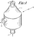
本発明の好適実施例によると、そして図面の図1、図2および図3に特に注意を向けると、全体を10で示したポンプは、ハウジング11を含み、その内部が全体を12で示されたポンプ作用室を画成している。言い換えれば、ハウジング11の内周縁13は、ポンプ作用室12の外周縁である。図2および図3の図から明らかなように、ハウジング11およびポンプ作用室12は、図2に描かれているように軸線14に沿って延びる中心軸線を共有している。ハウジング11、および、それによりポンプ作用室12は、18におけるような流出孔に加えて、16および17におけるように一対の流入孔を具備している。流入孔16、17は、集合的に、ポンプ作用室への入口を画成し、一方流出孔18が出口を画成する。流入孔16および17は、ポンプ作用室と同軸線上に、即ち、軸線14に沿って配置され、流入孔は軸線14に対して横切ってかつポンプ作用室12に対して対向した配置関係で配置されている。流出孔18は、流入孔の中心軸に配置され、かつ、図示されるように、軸線14に対し全体的に横切って配置されている。
【0028】
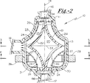
続いて図面の図2および図3に注意を向けると、全体的に20で示されるロータ、すなわちロータ組立体は、ポンプ作用室12の内部に配置されかつ対称的な複円錐形状を有している。この形状は、19Aおよび19Bのような対向した極領域に向って集合する複円錐を具備したコア部分、すなわちロータコア19を提供し、そして、ロータは、極端区域間に延びる回転軸線を具備して提供される。ロータコア19の複円錐形状を形成する2つの円錐体の各々の基礎部は、一緒に連結されかつ共通の中央面を形成する。ロータコア19とシュラウド23との間には、複数個の羽根が位置決めされ、羽根の対向した端部が図2に示されている。これらの羽根は、また、図4に断面で示されている。ロータコア19にはシュラウド23が連結され、このシュラウド23は、連結ロッドまたはポスト24−24によってロータコア19に連結され、それにより全体的に25で示される環状流路に、流れを促すための付加的な流体接触区域を生じさせる。外方向流路は、また、26におけるようにロータ組立体20に環状にかつその外面上に画成されている。
【0029】
複数個の永久磁石が27−27におけるように設けられ、これらの磁石がロータ20の中間平面の下方または上方の半径方向に離隔された位置にかつロータの回転軸線に沿って配置され、これらの永久磁石は、均等に半径方向にかつ円弧状に離隔された位置に設けられている。電磁駆動手段は、28−28におけるように設けられ、この電磁駆動手段は、順次、電気エネルギー源に連結されかつ永久磁石27−27を通してロータへ回転駆動エネルギーへ供給すべく配置されている。駆動装置は、勿論、ブラシレスモーター構成として普通に参照されるものであり、そして、ブラシレスモーター駆動は、勿論、技術的に良く知られている。ロータ20の回転速度は、電磁部材28−28に適用される磁場周波数によって都合よく制御され、その回転速度は、適用された電磁場の周波数によって、あるいは電磁手段28−28の選択的な付勢によって制御される。このような駆動は、勿論、普通に使用されかつ技術的に良く知られている。
【0030】
ロータ20は、さらに、シュラウド23に加えて壁21および22によって画成され、構成部材がハウジング11に採用されているものと類似しているかまたは同一であるかのいずれである。ポリカーボネイト、アクリル樹脂、あるいはポリスチレンの共重合体のような適当な生物学的適合材料が採用されてもよく、あるいは、それに代えて、コーティングが、その構成の生物学的適合性を高めるために適当な基板に塗布されてもよい。移植のための装置が採用されていない場合には、その際、勿論、血液接触表面が形成されおよび/または非トロンボゲン材料で被覆されるならば、他の材料が採用されてもよい。
【0031】
ロータ20は、中空コアまたは表面32の内部的な空隙区域を具備していて、この区域は、ロータ本体の相対的な密度を制御する手段を提供している。好適には、相対的な密度は、汲み上げられる流体の密度に対するロータの相対的な密度の比によって選択され、殆どの適用において、汲み上げられる流体に対するロータの相対的な密度が約0.3と0.6との間にあり、約0.1と0.9との間にの相対的な密度が有益であると見出され得ることが理解されている。ロータ材料が汲み上げられる流体の密度より低い密度を有する場合、コアおよびシュラウドにおける空隙は、勿論、除去され得る。
【0032】
ロータ20とそのシュラウド23の双円錐形状は、入口ポート16,17間のポンピング室の軸線方向長さにほぼ等しい回転軸線に沿った軸線方向長さを備える完成構造を形成する。ロータの横方向直径は中央線33のような中央平面に沿って定義され、図7により詳細に示されるように合体する双円錐の形状はシュラウドの表面とポンピング室の内面との間に隙間を形成する。全体的に、隙間は、A―AとB−Bとに示されるように、入口ポート領域から出口ポート領域までほぼ一定であり、しかしまた、出口に向かって僅かに発散或いは収束している。隙間寸法は極先端領域の間の中央平面までの層流を確保するのに好適な流量を提供するのに充分である。シュラウドの形状はそのような層流の保持に役立つようにされている。これらを念頭に置いて、ポンピング室の内面とロータシュラウドの周囲との間の隙間は好適には約1ミリメートルから約7ミリメートルまでの範囲であり、約1ミリメートルから約3ミリメートルまでのより狭い範囲が一般的に好適である。シュラウド23の外面とハウジング11の内面13との間の隙間は、約1.5ミリメートルであることが好適である。
【0033】
入口ポートと出口ポートの面積に関して、入口ポートの組み合わされた面積は出口ポートの面積に少なくてもほぼ等しいことが好適であり、それにより、流れと圧力の整合が向上し、室12内でのロータ20の流体力学的バランスが適正化される。複数の出口ポートが採用される場合、出口ポートの組み合わされた面積は入口ポートの組み合わされた面積にほぼ等しいことが好適である。
【0034】
図示されるように、電磁駆動要素28−28の駆動手段は好適には、好適には導体コイルの形態であり、適切な流体力学的バランスを達成するために、コイルは、ベアリングの形態の必要を省きつつ回転ロータの流体力学的バランスを維持するように選択的に製造され且つ注意深く制御される。
【0035】
示されたように、インペラーの慣性モーメントは、インペラーの質量を重心(又は質量中心)により近く配置することにより効果的に最小化される。これは、構造的完全性のために必要とされるインペラーの質量を重心により近く移動させることにより達成され、回転軸線にできるだけ近く移動される。慣性モーメントは、回転軸線に沿って構造強度を増加させつつロータシュラウドの必要とされる最大半径にできるだけ近い円形或いは環状領域内に永久磁石を配置し且つ装着することにより、本発明の構造に関連して制御可能に調節されても良い。この特徴は、永久磁石27−27が下シュラウドセグメント30の外周に隣接して配置されている図2に示されている。
【0036】
従って、図2に示される形状において、下シュラウドセグメント30は、ロータコア24に対して同心に配置されつつ、永久磁石を包囲し或いは収容し、同時に、31で示されるように環状流通路を配置する。
【0037】
圧送される流体に関して、人間の血液は、25℃において約4センチポアズの粘性を有することが留意されるべきであり、この粘性は、相対的に滑らかな回転面と血液との間の充分な摩擦を形成して流体力学的バランスのための充分な回転運動成分を得るのに充分である。ここに示されるシュラウドで覆われたロータ形状において、シュラウドは付加的な接触領域を形成し、相対的に滑らかな回転面と血液流体の利用を受け入れることが注目される。
【0038】
圧送される流体の回転速度が増加すると、その流体力学的バランス効果は、無論、相応して比例増加する。約1000rpmの回転速度では、流体力学的バランス効果は、室内のロータの相対比重によりもたらされる浮揚効果をほぼ打ち消す。
【0039】
始動目的のために、塩類が機能性材料として通常は好適であり、塩類は望ましい回転速度が得られるまでの時間使用され、その後、圧送され及び/又は移送される作動溶液として血液が導入されてもよい。
【0040】
示されるロータ構造が相対的に滑らかであると記載される一方で、羽根がロータ内で弧状に形成され間隔をおかれた複数の通路を形成して構造上に使用されても良い。言い換えるなら、羽根は、独立して弧状に間隔をおかれた櫂として形成され、間隔を離された流体通路及び/又は溝を形成しても良い。複数の羽根が、コア19の外面とシュラウド23の内面との間に図2と図4に示されるように配置される。加えて、望まれるなら、支持の形態は、組立体のこれらの要素が羽根と同様に機能しても良い。したがって、示される羽根は丸くなった端縁を備える他、楕円形のような他の羽根形状が採用されても良い。
【0041】
入口と出口の直径は好適には7ミリメートルであり、相対比重は好適には0.1から0.9の間であり、0.5の相対比重が好適である。
【0042】
大部分の操作目的のために、約5ミリメートルHg(水銀)から約40ミリメートルHg(水銀)までの範囲の入口圧力が通常であり、且つ人間の血液を扱う流体力学上適当である。約40ミリメートルHg(水銀)から約150又は200ミリメートルHg(水銀)までの出口圧力が使用されても良い。本発明の装置が植え込み可能なユニットとして作用する場合、出口圧力は無論、患者の活動や循環系の要求に応じる。
【0043】
図5を参照すると、改変された駆動形状とシュラウド形状が示されている。図5において、例えば、シュラウド40はロータコア19の回りで対称に配置される。これに関連して、しかし、シュラウド40の上下両方の部分が対称であり、第二環状流路41,42を形成する。加えて、主又は先行環状流路43,44が、図示されるように形成される。
【0044】
この配置において、しかし、対称に配置される双駆動機構は、永久磁石組立体27A,27Bと、駆動磁石28A,28B,29A,29Bをそれぞれ備える。シュラウド形状を除けば、図5のその他の形状は図1と図2に関連して示され記述される形状と同じである。
【0045】
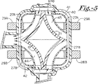
図6を参照すれば、改変されたシュラウド形状が示され、ロータコア19は一対の同心に配置されるシュラウド45,46をそれぞれ備えている。図6の配置において、内シュラウド45はロータコア19の周りで全体として対称であり、外シュラウド46は、図2に示されるシュラウド部分30と形状が類似する下セグメント或いは部分47を備えている。図6の形状において、複数の環状流路が、ロータコアと内シュラウドとの間に48で示されるように、内外シュラウドの間に49で示されるように、外方環状領域において外シュラウド46とハウジング11の内面50との間に、形成され、この外方環状流路は51で示される。図6に示される複数シュラウドを備えるロータ形状は、図5に示される構造の態様で双駆動機構を備えて改変されても良い。
【0046】
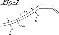
ここで図面中の図7に注意を向けると、部分断面図であるこの図7は、ロータシュラウドの外側面とハウジング間の間隙の形状を示している。この図7において、ハウジングの内側面は53で示され、ロータシュラウドの外側面は54で示されている。
【0047】
ここで図面中の図8に注意を向けると、ポンプ10は消化器官または心臓−支援装置として機能するシステム内に連結されている。ポンプ10は電源60によって駆動され、ピックアップ比率センサ61および比率制御装置62を含む、複数のセンサが使用されている。患者の圧力レベル監視装置63は、64における患者の圧力レベル入力および圧力レベル信号65を含む情報を受信するレベル監視装置を備えた比率制御装置62に対する入力となる。こられの装置は当業界では周知のものであり、本発明の装置と接続して効率的に使用し得る。
【0048】
従来から二重シュラウドが検討されてきたが、ロータシュラウドのコアには外側コア面から軸線方向外向きに配置された複数の回転面、およびロータシュラウドの回転軸と同軸な関係に配置された複数の回転面が設けられている、多重シュラウドを使用し得ることができる。
【0049】
”二重円錐体形状”という用語がロータシュラウドのコアに対してあまねく使用されてきたが、放物線のような曲線、あるいは直線によって生成されもって円錐体を構成する、他の回転面を使用し得ることも理解されよう。このように、”円錐体”という用語は、本明細書では広く定義されていることが理解される。さらに、図5に示されているロータシュラウドに接続して示されているような改変された回転面も使用し得る。
【0050】
(第2あるいは代替的好適実施例の説明)
本発明の第2の好適実施例によれば、および特に図面中の図9、図10および図11に注意を向けると、全体的に110で示されているポンプは、その内側がポンピング室112を画成するハウジング111を有する。換言すれば、ハウジング111の内側周辺113はポンピング室112の外側周辺でもある。図10および図11から明らかなように、ハウジング111およびポンピング室112は図10に示された軸線114に沿って延在する中央軸線を共有する。ハウジング111、および従ってポンピング室112には、116及び117で示すような一対の入力ポートが設けられている。入力ポート116及び117は、ポンピング室112への入力をひとまとめにして規定する一方、出力ポート118は出力を規定する。入力ポート116及び117は、ポンピング室112、即ち軸線114に沿って同軸な関係に配置されており、入力ポートはポンピング室112に対して反対両側配置関係で配置されている。出力ポート118は、入力ポート、および図示するように軸線114を全体的に横切って中間に配置されている。多重出力ポートを使用することができ、および結局、各ポートは典型的には出力ポート118に対して図示された配置と一致するべく、複数の入力ポートの中間に配置されていることに注意すべきである。
【0051】
図面中の図10及び図11にさらに注意を向けると、全体的に120で示されているロータは室112内に配置されていると共に、改変された対称二重円錐体形状を有している。この形状は、123及び124のような反対両側の極領域に収斂する、二重円錐体121及び122を形成し、およびロータには、極領域123及び124間に延在し、通常は軸線114と一致し且つ該軸線114と同軸な関係にある、回転軸線が設けられている。二重円錐体形状を構成する2つの各円錐体の基部は相互に連結されて共通の中央板125を形成する。二重円錐体121及び122の外側面には127−127で示すような、複数の半径方向羽根が設けられている。羽根127−127は、図10に示されているように、円錐部材121及び122の外側面から軸線方向と半径方向に延在する面部分を備えて配置されている。さらに、羽根127−127は、磁石128−128のような複数の永久磁石に対する装置基部として用いられる。これらの磁石は、半径方向に隔置された位置に配置されており、該位置は中央板125から全体的に軸線方向に等しく隔置され且つロータ120の回転軸線から半径方向外向きにある。永久磁石128−128は半径方向に等しく且つ円弧状に隔置された位置に設けられている。電磁石駆動装置は129−129および130−130に示すように設けられ、電磁石駆動装置は、順番に電気エネルギー源に連結され且つ永久磁石128−128を通じて回転駆動エネルギーをロータシュラウドに供給すべく配置されている。勿論、駆動装置はブラシレスモータ形態とされるのが慣用であり、ブラシレスモータ駆動装置は、勿論、当業界では周知である。回転数が印加された電場の周波数によって、あるいは電磁装置129−129および130−130を選択的に励磁することによって制御される状態では、ロータ120の回転数は都合よくは電磁石129−129および130−130に印加された周波数によって制御される。このような駆動装置は、もちろん、当業界では慣用され且つ周知である。
【0052】
ロータ120の構成材料は、ハウジング111で使用されたものに類似しているか等価なものである。構造体の生物学的適合性を向上させるために、ポリカーボネイト、アクリル樹脂、ポリスチレン共重合体のような適切な生物学的に適合する材料を使用し得るか、あるいは代替的に適切な基体に対して被覆を施すこともできる。装置が移植のために使用されないこれらの例においては、血液が接触する複数の面が形成され(および/または)非トロンボーゲン材料で被覆されるものと仮定すると、勿論、他の材料を使用することもできる。
【0053】
ロータ120は、中空コア若しくは中空室領域132を有し、その容積若しくは領域は、ロータ本体の相対密度を制御する手段になっている。好ましくは、その相対密度は、ロータの密度とポンプ作用をうける流体の密度との比率によって選定する。多くの用途において、ポンプ作用をうける流体に対するロータの相対密度は約0.3と0.6の間にあり、約0.1と0.9との間が有用な範囲である。また、ロータ120の複式円錐形状は、回転軸線に沿う軸線方向長さが入口ポート116と 117との間のポンピング室の軸線方向長さとほぼ等しい最終構造体を提供する。ロータ120の横方向の径は、中央線125のような中央平面に沿って定められ、複式の収斂する円錐体の形状と半径方向ベーンは、図12に詳細に示されるように、ロータのベーンの表面とポンピング室の内面との間に間隙を与えるようなものになっている。一般にA−A及びB−Bで示した間隙は入口ポート領域から出口ポート領域まで一定に維持されるようなものであるが、その間隙は、出口に向かってわずかに収斂し又はわずかに末広がりになっていても良い。132で示されるようなベーンの周囲と複式円錐体121、 122の外面との間の間隔は、好ましくはほぼ一定であり、また、ハウジング111の内面113にほぼ平行である。ポンプ作用をうける流体の移送のための容積が得られ、ポンプ作用をうけた流体の子午線速度は、その流体が並進及び回転運動経路、及び/又はベクトル、に沿って移動してポンプを通る間にほぼ一定に維持される。これらの点を考慮し、ポンピング室の内面と半径方向ベーン127−127若しくはロータ120の外縁との間の間隙は、好ましくは、約1ミリメートルと7ミリメートルの間の範囲とされる。一般的に好ましい範囲は、約1ミリメートルと3ミリメートルの間のより狭い範囲である。一般に、約1.5ミリメートルの間隙が好ましく、その間隔は図12の対向する矢印A−A及びB−Bの間の区域として寸法的に図示されている。
【0054】
入口ポートと出口ポートの面積に関しては、一般に入口ポートを結合した面積(若しくは入口ポートの総合面積)が出口ポートを結合した面積(若しくは出口ポートの総合面積)とほぼ等しく、それによって流れと圧力の一貫性を与え、室112内のロータ120の適切な流体力学的バランスを得るようにするのが好ましい。
永久磁石128−128は半径方向ベーン127−127内に収納されている。図10に示されているように、収納された永久磁石128−128の物理的位置は、ベーン127−127の半径方向端縁の外面に近接している。その半径方向端縁の外面は133で示されている。
【0055】
電磁的駆動要素129−129及び130−130のための駆動手段は、好ましくは導体巻線の形態をなし、適切な流体力学的バランスを得る目的で、巻線は、回転するロータの流体力学的バランスを維持ししかも如何なる形態のベセアリングをも必要としないようにするように、慎重に制御されかつ選択的に製造される。
ロータ若しくはインペラの慣性モーメントは、インペラの質量を重心若しくは質量中心に接近して位置させることにより、効果的に減じられる。このことは、構造の完全性のために必要なインペラの質量を中心により近づけ、一般に回転軸線にできるだけ近づけることにより達成することができる。本発明の構造に関して慣性モーメントは、ロータ内部インペラの最大半径のところにある円形又は環状領域内に永久磁石を配列装架し、同時に回転軸線に沿う構造体の強度を増加させるようにして、制御可能に調節されると良い。
【0056】
ポンプ作用をうける流体に関しては、人間の血液は25℃において約4センチポアズ(centipoises)の粘度を有し、その粘度は、ベーンとロータ表面との間に血液に対する適切な摩擦を与えて流体力学的バランスを得るための運動の十分な回転成分を得るために十分なものである点に留意すべきである。もちろん、ポンプ作用をうける流体の回転速度が増加すると、それに相当しかつ比例して、流体力学的バランス効果は増大する。約1000rpmの回転速度では、流体力学的バランス効果は、室内のロータの相対密度によって与えられる浮力効果より実質的に大きくなる。
【0057】
最初の目的のために、含塩物は通常、機能物質として好適である。所望の回転速度が得られるまで含塩物が用いられると、その後、血液はポンプでくみ上げられ、及び/又は運ばれる作動溶液として導入される。
内径及び外径は、望ましくは7ミリメートルであり、相対濃度は望ましくは0.1から0.9の間であり、0.5の相対濃度が好適である。
最も作用的な目的のために、約5ミリメートル水銀から約40ミリメートル水銀の範囲の内圧が、人間の血液を扱う流体力学のために一般的で望ましいものと考えられる。約40ミリメートル水銀から約150あるいは200ミリメートル水銀の外圧が、採用される。本発明の装置が、移植可能なユニットとして機能する時には、外圧はもちろん、患者の機能や示される循環要求に依存している。
【0058】
本発明のポンプ装置は、大動脈に結合された出口を有する装置として使われるポンプを備えた患者補助ユニットとして使われ得る。別の構造においては、出口は、肺動脈に結合され得る。上述したように、本発明の装置は、搬送ポンプとしても適用されるので、一時的に心臓の機能をとめてしまう外科手術においても利用され得る。
図13について説明すると、ポンプ110は、心室あるいは心臓補助装置として機能する装置に連結される。ポンプ110は、動力装置150によって駆動され、ピックアップ比センサー151を有するセンサー及び比コントローラ152が用いられる。患者の圧力レベルモニター153が、比コントローラー152に入力を与え、レベルモニターは患者の圧力レベル入力154と圧力レベル信号155を有する情報を受信する。これらの装置は、公知であり、本発明の装置と関連付けて効果的に利用され得る。
【0059】
再び、先に記載した好適実施例と関連付けて述べると、「2重円錐形状」なる用語が、全体を通して用いられたが、その他の回転表面が利用できることは理解されるであろう。放物線のような曲線や直線によって作られる回転表面が利用され、これにより円錐形が形成される。従って、「円錐」という用語は、ここでは広義に用いられる。
【0060】
(第3のあるいは追加の好適実施例の説明)
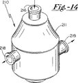
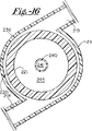
本発明の第3のあるいは追加の好適実施例によれば、また、特に図14、15、16に関連して、一般に210で示されるポンプは、ハウジング211を有しており、このハウジングの内部は、一般に212で示されるポンピング室を画定している。言いかえれば、ハウジング211の内周面213は、室212の外周面である。図15、16、17から明瞭であるように、ハウジング211と室212は、図15に示される軸214に沿って延びる中央軸を共有している。ハウジング211及び室212は、出口218、219に沿った主入口216を備えている。入口216は、室への入口を画定しており、出口218、219は全体として出口を画定している。外側の入口216は、室と同軸に配置されている、即ち、軸214に沿って配置されており、又、外側の入口は、デフレクターチップの頂点243に隣接する第2のあるいは内側の入口217に対向するように配置されている。外側ポート218、219は、第1の及び第2の入口の中間に配置されており、上述したように、一般に軸214を横切って配置されている。
【0061】
引き続き図15、図16を参照して、ロータ220はチャンバー212内に配置され、対称な複式円錐形状のコア構成要素221を有している。この形状は221や222のような相対する極端領域に向かって収斂するする円弧形状の複式円錐形を備えており、このロータは、極端領域221、222の間を延び、軸線214にほぼ沿ってかつ該軸線と一致する回転軸線を備えている。複式円錐形状を形成する二つの円錐形のそれぞれの底部は互いに結合され、223として共通の中央面を形成する。ロータコア221はまた224、225、226、227としての一対の円錐形状のシュラウドを備えている。シュラウド224、225、226はそれぞれほぼ円錐形状であり、この円錐形は円弧状セグメントの回転表面として形成されており、この回転セグメントは実質的に複式円錐形の半径と合致する半径を有している。さらにシュラウド227は、227Bとしての外部セグメントに沿った227Aとしての内部円弧セグメントを有している。セグメント227Aと227Bは互いにその端部で結合され、円弧セグメント227Aと227Bによって全体的に規定されている取り囲まれた回転表面を形成し、その結果、修正されたトロイド形状を有する部材が生じる。
【0062】
個々のシュラウドはポストまたは輻をつけられた円板(spoked discs)228−228によってコア構成要素21に結合される。円板228−228はコア構成要素221の外部表面229の間にリンクを備え、そうして組立体全体に対して機械的な安定性と剛性とを備える。シュラウド224、225、226、227とコア構成体221の形状は、231、232、233としての環状流路を組立体の下部に隣接する同様な環状の形状の通路234、235、236にそって組立体の上部に構成する。修正されたトロイド状部材227の領域内では磁石237−237のように一連の永久磁石がある。これらの磁石はロータ220の回転軸線に沿ってほぼ中間で半径方向に間隔を取った位置に配置され、永久磁石は半径方向に等間隔でかつ円弧状に間隔を取った位置に設けられる。電磁石駆動装置(electromagnetic drive means)は238−238として設けられ、この電磁石駆動装置は、続いて電気エネルギ源に接続され、永久磁石237−237を介してロータに回転駆動エネルギを伝えるよう配置される。駆動装置(drive arrangement)は勿論ブラスレスモータの形状として一般的にいわれていて、ブラスレスモータ駆動は勿論当分野において公知である。ロータ220の回転速度は従来電磁石部材238−238に適用される場の周波数(the frequency of the field)によって制御され、回転速度は適用される電磁石の場の周波数(the frequency of the applied electromagnetic field)によって、または電磁石装置238−238の選択的エネルギ化(selective energization)によって制御される。そのような駆動は勿論当分野において、通常使用されかつ周知のものである。
【0063】
ロータ220は外部表面又は壁220によって規定され、構造材料はハウジング211に使用されたものと類似か同一のものである。ポリカーボナイトやアクリル、ポリスチレンの共重合体などのような適当な生体適合性のある材料(biocompatible material)でも使用可能であり、または代替的にコーティングが、構造の生体適合性を高めるために適当な基質(substrate)に使われてもよい。その装置が移植(implantation)に使用しないこれらの例では、血液と接触する表面(blood−contacting surfaces)が非トロンボゲン材料(non−trombogenic material)で形成され及び/またはコーティングされているならば、勿論他の材料が使用可能である。ロータ材料が圧送される流体より低比重(lower density)であるならば、コアおよびシュラウドに形成された空所及び/または空洞は除去される。
ロータ220は全体として241で示される軸方向の穴(axial bore)を規定する管状コア240を備える。穴241は入口216から液体を受け入れ、第2入口帯またはチャンバー242に直接流体を送り、最終的に環状通路234、235、236を介して伝達され流れる。示されたように、これらの通路のそれぞれは出口218に導き、それによって流れの連続性を与える。243として設けられる頂点は、スムーズな流れ、好ましくは層流を、ポンプ組立体を介して与える。
【0064】
さらに、中空のコアまたは空所領域がロータコア221内に設けられ、このチャンバーは全体として245として示される。このチャンバー領域は回転体の相対的比重(relative density)を制御する手段を規定する大きさの体積を与える。更なる浮力が部材227の修正されたトロイド形状によって与えられ、それによって、全ロータ組立体に対する相対的な比重が与えられる。好ましくは、この相対的な比重は圧送される流体の相対的比重に対するロータもしくはロータ組立体の相対的比重の割合によって選択され、ほとんどの適用において、圧送される流体に対するロータの相対的比重は大体0.3と0.6の間であり、大体0.1と0.9の間の相対的比重が使用可能となることが理解される。また、シュラウドと共にロータ220のコア構成要素221の複式円錐形状は仕上げられた構造を備え、回転軸線に沿った軸線長さは第1入口ポート216と第2入口ポート領域242の間の圧送チャンバーの軸線長さと略等しい。ロータ220とそのシュラウドの横断直径は、中央線223に沿うのと同様に中央平面に沿って、規定され、図18に拡大されかつ詳細に示されるように、複式収斂円錐形の形状はロータの表面と圧送チャンバーの内面の間の隙間を設ける。概して言うならば、A−AやB−Bで示される隙間は第1及び第2入口ポートから出口ポートまで一定である隙間である。個々の流路の組み合わされた領域では、圧送された流体に対する運動の割合が移行及び回転運動及び/またはベクトルにそって移動するとき実質的に一定である。これらの考慮によって、圧送チャンバーの内面とロータの外周の間の隙間は好ましくは、大体1mmから大体7mmまでの間までに入り、大体1mmから3mmの間の狭い領域が血液にとって好ましい。一般的に、大体1.5mmの隙間が好ましい。
【0065】
入口ポートと出口ポートの間の領域について、一般的に好ましいのは、第1入口ポート216の組み合わされた領域がほぼ出口ポート218と219の組み合わされた領域に等しいことであり、それによって、流れや圧力のより一貫性(more consistency)が与えられ、また、チャンバー212内のロータ220の適切な流体力学的な平衡が与えられる。
示されるように、電磁石駆動要素238−238への駆動装置は伝導体の巻き取り(conductor windings)の形状が好ましく、適切な流体力学上の平衡を得るために、その巻き取りは注意深く制御されかつ選択的になされて、受けのどのような形状に対する必要性も除く一方で、回転ロータの流体力学上の平衡を保つようにする。
【0066】
示されるように、羽根車(impeller)の慣性モーメントは重心または重量の中心により近い羽根車の質量の位置により効果的に最小にされる。これは中心により近い、そしてほぼ回転軸線に対しできるだけ近い構造上の完全性(structural integrity)に必要とされる羽根車の質量を移動することによって得られる。慣性モーメントは本発明の構造に関連して、その回転軸線に沿って構造強度を増加させながら、必要ならば、ロータ内部羽根車の最大径である円形又は環状ゾーン内に永久磁石を配置かつ取付ることによって、制御可能に調節することができる。図15に示されるように、例えば永久磁石237−237は修正されたトロイド状部材227の範囲内に位置され、それによって、永久磁石を効果的に圧送された血液との接触から離しておくことができる。
ポンプ送りされる流体について、人間の血液が温度25℃で約4センチポイズの粘度を有すること、そして、水圧バランスのための十分な回転運動成分を達成するために、この粘度は、ロータおよびシュラウドの比較的円滑な表面と血液との間に十分な摩擦を与える上で十分であることに留意すべきである。ポンプ送りされる流体の回転速度が増すと、勿論、その水圧バランス効果が、それに応じ比例して増す。概ね1000rpmの回転速度では、水圧バランス効果が、室内のロータの相対密度によってもたらされる浮遊効果に実質的に打ち勝つ。
【0067】
運転開始用として、通常、塩類(塩類は、所望の回転速度に達するまでの間使われる)が作動材料として好ましく、その後、ポンプ送りされ、および/または、搬送される作動溶液として、血液が導入されるだろう。
図示のロータ構造は比較的円滑である旨説明されているが、その構造に対して複数のベーン(翼)を使用可能であり、それらのベーンは、ロータ内で正確に間隔を置いて形成される。換言すれば、仮にベーンを採用する場合には、間隔を置いた流体通路および/または流体チャネルを作るために、それぞれアーチ状に間隔を置いた複数のパドル(水かき)として翼が形成されるだろう。
入口径および出口径は好適には7mmであり、相対密度は好適には0.1〜0.9である(0.5が好ましい)。
【0068】
大部分の運転目的にとって、入口圧力約5mmHg(水銀)〜約40mmHg(水銀)が普通であり、人間の血液を取り扱う流体動力学にとって適切であると考えられる。出口圧力としては、約40mmHg(水銀)〜約150または200mmHg(水銀)を採用できる。本発明装置は、植設可能な装置として働く時、出口圧力は、もちろん患者の活動および循環条件に依存するだろう。
図19を見ると、患者支援ユニットとして本発明のポンプ装置を使用するためのシステムについて説明されている。図19では、大動脈に接続される出口を有する装置としてポンプ250が採用されるだろう。代替構造では、出口が肺動脈に接続されるだろう。指摘したとおり、本発明装置は、搬送ポンプとしての用途も有し、したがって、心臓機能を一時的に移し、および/または、心臓機能を一時的になくす外科処置で使用できる。
【0069】
ポンプ250は、心室装置または心臓支援装置として働くシステムに接続される。ポンプ250は、動力供給装置251によって動かされ、ピックアップ比センサー252を含むセンサーと比率制御253が採用される。254における患者圧力水準入力および圧力水準信号256を含む情報を受ける患者圧力水準モニター255が、比率制御253に入力を与える。これらのシステムは、当業界で公知であり、本発明装置と連結して効果的に使用可能である。
2重円錐形について議論したが、多重円錐形を翼の代わりに使用できる。その場合、ロータの軸線方向外側であってロータの回転軸線と同軸に配置された回転表面がロータに与えられる。
用語「2重円錐形」が明細書全体に亘って採用されているが、円錐形を作るために、放物線、双曲線のような曲線または直線によって作られる他の回転表面を使用できることを理解できるだろう。したがって、本明細書中の用語「円錐形」は広義の意味で用いられる。
【0070】
前記好適実施例において各種の変形が可能であり、その変形は、本発明の精神と範囲を逸脱することなくなし得ることも理解できるだろう。
【図面の簡単な説明】
【図1】本発明により用意されたポンプ組立体の斜視図である。
【図2】図1に示すような構造体の軸線を通る垂直断面図であって、ロータコアおよびシュラウドを含むロータの形態を示し、更に実際の作動の際に該ポンプにより形成される流れパターンを示す図である。
【図3】図2の矢印3−3の線に沿いかつその方向に取った水平断面図である。
【図4】図2の矢印4−4の線に沿いかつその方向に取った水平断面図である。
【図5】図2に類似した図であって、駆動要素用の変更形態を示す図である。
【図6】図6は、図2と同様な図であってかつロータ用の変更されたシュラウド形状を図示したものである。
【図7】図7は、僅かに拡大された寸法にされた破断断面図であってかつロータとハウジングとの間の間隙の形状を図示したものである。
【図8】図8は、本発明の装置が機能し得る典型的ななシステムを図示した概略線図である。
【図9】図9は、本発明にしたがって作成されたポンプ組立体の別の好適実施例の斜視図である。
【図10】図10は、図9に描かれた構成のロータ部分の回転軸線を通ってとられた組立体の縦断面図であって、図11の矢印10−10の方向においてその線に沿ってとられ、さらにポンプの駆動構成要素の配置を図示したものである。
【図11】図11は、図10の矢印11−11の方向においてその線に沿ってとられたポンプの横断面図である。
【図12】図12は、僅かに拡大された寸法にされた破断断面図であってかつロータとハウジングとの間の間隙を図示したものであり、そして流体の一部がその組立体を通って流れる状態を図示したものである。
【図13】図13は、本発明の装置が機能し得る典型的なシステムを図示する概略線図である。
【図14】図14は、本発明にしたがって作成されたポンプ組立体のさらに別の好適実施例の斜視図である。
【図15】図15は、ロータの軸線を通ってとられた縦断面図であってかつ実際の作用中であるときポンプによって生じられるフローパターンを図示するものである。
【図16】図16、図15に図示されたポンプ構成の横断面図であって、かつ図15の線16−16に沿ってとられた横断面図である。
【図17】図17は、図15に図示されたポンプ構成の横断面図であって、かつ図15の線17−17に沿ってとられた横断面図である。
【図18】図18は、拡大寸法にされかつロータの外部とハウジングの内部との間の間隙の大きさを図示した破断断面図である。
【図19】図19は、本発明の装置が機能し得る典型的なシステムを図示した概略線図である。
【符号の説明】
11 ハウジング
12 ポンプ作用室
13 内周縁
14 軸線
16 流入孔
17 流入孔
18 流出孔
19 コア
20 ロータ
21 壁
22 壁
23 シュラウド
24 連結ロッド
25 環状流路
26 外部流路
27 永久磁石
28 電磁駆動手段
32 表面[0001]
(Cross-reference of related applications)
The present application is a continuation of application No. 08 / 456,503, which is a joint application with the applicant filed on June 1, 1995, and the name of the invention “Bearings and seals” on November 11, 1997. US Pat. No. 5,685,700 is now issued as a “free blood pump” and assigned to the same assignee of the present invention.
[0002]
(Background of the Invention)
The present invention relates generally to an improved rotor structure having radial vanes used as pumps for transferring fragile and aggressive fluids, where in some embodiments the vanes surround a magnetic drive element and / or Confine. Examples of fragile fluids include human or animal blood, and are generally not exposed to either unexpected shock / or turning forces. Active fluids include corrosive or toxic fluids as well as fluids that can damage the seal / bearing to reduce the life and longevity of the pump structure or tolerate contamination. For example, toxic fluids are very dangerous if leaked. The invention further relates to a bearing and a rotor of a pump that is seal-free, the rotor having a core body with one or more shrouds provided on the outer surface of the core, the outer surface of the core In parallel with each other. Furthermore, the rotor is dynamically balanced by hydrodynamics and buoyancy. In this configuration, the rotor design provides multiple parallel flow channels through flow enhancement in the fluid contact area. In other shapes, the vanes are provided between the core and the shroud or between shrouds for flow enhancement. In a configuration that utilizes a double shroud, the primary flow channel is formed between the shroud and the core, and the secondary flow channel is located outside the shroud. The primary channel provides a meridional channel and the secondary flow channel communicates flow between the inlet and the outlet. The pumps of the present invention are particularly suitable for human blood transport and can produce such a fluid flow without adversely affecting or damaging the quality of the pumped material. The rotor employed in the pump of the present invention comprising a double flow channel is preferably an electromagnetic drive system operating in conjunction with one or more rows of permanent magnets enclosed within radial vanes on the surface of the rotor. And the drive elements are arranged in the form of a brushless motor. Alternatively, a permanent magnet-permanent magnet coupling is employed. The device of the present invention provides a contrasting device that can achieve relative rotation and is equally bearing and seal free. In the past, pumps and pump systems have been designed to be bearing and seal free. Such systems typically employ magnetic airborne devices that are in effect the actual shape of the bearing, and are more similar to sleeve bearings, ball bearings, or other friction bearings. Such devices using magnetic bearings that are active and functional are complex and therefore require a large number of additional elements including magnetic devices, position sensors and fast-acting magnetic drives. Many such patents have been patented in the past, including Olsen et al. Patents 4,688,998 and 5,195,877. The device of the present invention is in stark contrast with these bearings and seals and has a central bore for the fluid flow inlet, as well as with a mechanical balance achieved through a combination of hydraulic and buoyancy. It has an annular channel located outside that provides flow through the pump structure. The rotor of the pump of the present invention provides a symmetrical arrangement of radial vanes that preferably surround the elements of the magnetic drive in order to improve and maintain the mechanical balance.
[0003]
There are inherent disadvantages of pumps that utilize friction-reducing bearings, including local heat generation, such as those resulting from the use of ball bearings, friction bearings, sleeve bearings, and the like. Slow flow and high pressure are generated locally through the use of such structures. In addition, such bearing pumps always use high springs, and small displacements of the rotor (or impeller) lead to very high forces that can break or effectively destroy the bearing. In addition, different forces are introduced into the structure whenever a change in axial position occurs.
In this construction, the pump further comprises a series of outer shrouds that are bearing and seal-free, and have a multi-annular flow channel, including a rotor having an inner bore for inlet fluid. It is required to hold the rotor in a predetermined position and can be designed to allow a relatively large displacement without generating a large force. The inner bore formed in the rotor is placed coaxially with the rotor so that fluid flow is easily achieved therein. In addition, the rotor finds an equilibrium position during active rotation and is offset (either rotational or transverse) from the housing axis in some way that occurs when the pump's rotational axis is changed. The rotational movement of the pump housing is manifested by rotor rotation or vertical axis displacement. This device was found to reduce the demand for high precision shafts in design, fabrication and operation. Eliminating the correct mounting rotation axis reduces the introduction of large forces that occur as the rotor axis deviates from its normal centered position.
[0004]
In addition to the outer surface of the rotor core, one or more shrouds are arranged coaxially with the outer surface of the rotor core in a shape that provides one or more annular channels for flow. In addition, the introduction of the blades acts as a paddle between the core and the shroud, or in the case of double shrouds, the device provides a flow channel through the rotor between the shrouds.
In one embodiment of the invention, the pump includes a pump chamber with a central shaft and a rotor body disposed within the bearing and seal free rotation chamber. The rotor has a core with a two-dimensional conical shape converging to the opposite polar zone and a rotating shaft extending between the polar zones.
In addition to the rotor core, to increase the area where one or more concentric shrouds contact between the pumped fluid and the surface of the rotor, and to provide an annular channel for fluid flow Is provided.
Further provided are radial vanes extending radially outwardly relative to the rotor rotational axis. These blades are used to improve flow and also provide an area surrounding the magnetic drive element. The magnetic drive elements are symmetrically arranged in an axially spaced relationship with the horizontal axis of the rotor.
[0005]
The fluid inlet is preferably arranged in the pumping chamber with its inner diameter coaxial with the rotor's rotational axis to provide inlet flow to both ends of the rotor. With this configuration, the inlet flow of the housing is divided into two substantially equal flow portions. The first flow portion flows into the rotor from one end adjacent to the housing inlet or the outer inlet, and the second flow portion is drawn through the inner diameter to the housing end opposite the outer inlet, where the second The direction of the flow portion is smoothly reversed and flows into the rotor from the opposite side. Thus, a portion of the fluid flow is conveyed to the portion of the rotor that is opposite in polarity to the housing inlet, i.e., the external inlet.
Except when the rotor is displaced, the rotor is usually placed in a coaxial relationship in both the pumping chamber and the fluid inlet. One or more outlets are located approximately in the middle of the chamber, i.e., in the middle between the inlets, and are typically located tangentially to the middle portion of the pumping chamber. When the rotor axis of rotation is arranged vertically, the double cone configuration is such that the flow in the annular channel along the outer surface of the rotor core descends along the top of the double cone and passes through the inner diameter of the rotor. Continue to rise along the bottom of the cone.
[0006]
The rotor in at least one embodiment provides fluid transfer between oppositely disposed fluid inlet zones, and the rotor inner diameter forms a fluid transport path whereby fluid can flow to the rotor at both ends of the housing. Led. The inner diameter provides communication at both ends of the rotor and allows the transport of fluid within the structure, whereby all fluid is first directed to a unipolar region of the housing. Thereafter, the fluid is transported directly through the interior to the oppositely disposed polar regions.
The term “opposed inlet” is intended to reflect the use of fluid introduction at both ends of the rotor, and is a configuration in which all pumped fluid is introduced into one polar region of the housing. It is also intended to include, nevertheless, the fluid is conveyed directly or oppositely through a polar region through the interior or exterior of the housing.
[0007]
The illustrated pump is in an operating mode where the rotor spins around its axis of rotation and all forces acting on the rotor are balanced. In the static non-operational mode where fluid is in the housing, only buoyancy acts on the rotor and the rotor is levitated at random positions. In a static non-operation mode with no fluid in the housing, the rotor is stable inside the housing under gravity.
As described above, the rotor is lifted by a combination of hydrodynamic force and buoyancy. Simply put, the buoyancy component can be obtained by carefully selecting the rotor density. Preferably, the relative density is between about 0.1 and 0.9 of the relative density of the fluid being pumped. “Relative density” means the density of the rotor measured relative to the density of the pumped fluid, as will be understood below. In dynamic motion mode, hydrodynamic forces become important and effective, and buoyancy becomes a less important secondary component.
The hydrodynamic force component is obtained as a result of fluid motion as the fluid moves through the pumping chamber. As the speed of the fluid increases, the hydrodynamic forces increase substantially, and with proper choice of rotor density, the hydrodynamic forces that occur during normal operation are accurate, steady and controllable and reproducible. Enables centering within the pumping chamber of a rotor with
[0008]
The intent of the present invention is to carry fluid from both inlet regions of the housing to an intermediate plane of the housing, combining both counterflows in this intermediate plane, then turbulent flow, flow separation, acute swirl, stagnation and other undesired By avoiding the condition, the fluid is directed to the outlet with minimal damage and loss. This is because the main flow is passed through the rotor channel, the secondary flow is passed between the inner periphery of the housing and the outer periphery of the rotor shroud, the intermediate surfaces of the housing and the rotor are aligned, and the electromagnetic drive means from the intermediate surface of the housing and rotor It is possible to achieve improved coupling and flow by separating the surfaces.
[0009]
The pump structure of the present invention is more suitable for conveying brittle and / or erosive fluids, particularly human blood. In particular, certain components of blood are extremely brittle and easily damaged when exposed to external forces, so conventional pumps are not at all suitable for this type of use. In addition, conventional seals and / or bearings in conventional pump structures inhibit substantial and important procedures and cause cell damage. A further feature of the pump of the present invention to provide a pump that is very suitable for blood transport is to provide essentially frictionless operation. The frictional force caused by the relative motion between the rotor and the stator gives a danger due to thermal energy and causes heat accumulation. Since blood is very sensitive to temperature changes, particularly temperature increases above normal body temperature, the reduction and / or apparent elimination of friction provides a substantial substantial advantage.
[0010]
Since the structure of the present invention does not require a bearing, energy consumption is reduced by eliminating energy loss in the bearing, otherwise including energy loss in the contact bearing, in addition to electrical loss in the magnetic bearing. The driving force for the impeller as a whole may be located at the center of gravity or the center of mass of the impeller, or adjacent to the center of mass and perpendicular to the axis of rotation. This feature results in the generation of the gyroscopic effect of the free object gyroscope, and the form of the invention is such that the impeller is stabilized when the housing axis rotates relative to the rotor axis of rotation. In other words, the rotation axis of the rotor may be changed due to a change in the position of the housing, and thus the rotation axis is not necessarily around the vertical axis but may be around the horizontal axis.
[0011]
In at least one embodiment of the present invention, the magnetic drive element is off the transverse axis of the rotor, and in this configuration, the center of gravity or center of mass of the rotor is displaced approximately from the geometric center in the direction toward the mounting location of the drive. I know that
[0012]
In addition to blood pump applications, the device of the present invention has other fluid related applications. Certainly, non-sensitive fluids, including the active fluids discussed above, may be properly processed and / or moved using the pump apparatus of the present invention. Removing the shaft, bearings and seals significantly reduces the manufacturing cost of the pump. Also, the pump has a practically infinite mechanical life under normal conditions. The device of the present invention has application for any fluid where economics, lifetime and uninterrupted operation are factors.
[0013]
A feature of one embodiment of the present invention is that it delivers fluid from the opposite inlet region of the housing to the center plane of the housing, combining two opposing flows at the center plane, turbulence, flow separation, sharp bends, stagnation, and By avoiding undesired conditions, the fluid is sent to the outlet port with minimal damage and loss to the fluid being dispensed. This involves coupling the upper and lower pairs of respective vanes of the single unit at the exit region, enclosing the permanent magnets at the outer tips of the vanes, and from the central plane of the housing and rotor. This is accomplished by moving the electromagnetic drive means.
[0014]
Also, according to the present invention, only a single pipe is required which is provided with a unique inlet to the housing and correspondingly connected to the pump. The deviation of the drive means from the outlet / center plane of the housing makes the construction, operation and maintenance of the pump more convenient and allows the use of conventional drive means, especially in the form of permanent magnets to permanent magnets.
[0015]
(Summary of the Invention)
Accordingly, a main object of the present invention is an improved pump for transferring delicate fluids such as human blood, wherein the pump has no bearings or seals and the rotor is spaced apart from the outer surface of the rotor. Wherein the rotor has at least one shroud forming one or more annular channels, the rotor having a radial vane surrounding the magnetic drive element adjacent to the radial outer end, the rotor comprising: It is balanced dynamically during rotation by a combination of hydrodynamic forces and buoyancy, and preferably has an internal bore formed therein that allows the incoming fluid to be transferred from one extreme of the rotor to the other. Is to provide a simple pump.
[0016]
Another object of the present invention is to provide an improved pump for human blood that can create a uniform and unaltered flow of fluid without damaging or otherwise adversely affecting the quality of the material being dispensed. Is to provide.
[0017]
Yet another object of the present invention is a pump structure utilizing a pumping chamber that houses a rotor with a shroud, which is attached to the rotor in a brushless form and spaced apart from a disposed radial vane. It is to provide a pump structure that achieves rotation of the rotor by means of an electromagnetic drive that operates in conjunction with a row of permanent magnets arranged.
[0018]
Other and other objects of the invention will become apparent to those skilled in the art upon review of the following specification, claims and drawings.
[0027]
(Embodiment of the Invention)
According to a preferred embodiment of the present invention, and with particular attention to FIGS. 1, 2 and 3 of the drawings, the pump generally designated 10 includes a housing 11, the interior of which is generally designated 12. A pumping chamber is defined. In other words, the inner
[0028]
Turning now to FIGS. 2 and 3 of the drawings, the rotor generally indicated at 20 I.e. rotor assembly Are arranged inside the
[0029]
A plurality of permanent magnets are provided, such as at 27-27, and these magnets are disposed radially spaced below or above the midplane of the
[0030]
The
[0031]
The
[0032]
The biconical shape of the
[0033]
With respect to the area of the inlet and outlet ports, it is preferred that the combined area of the inlet ports be at least approximately equal to the area of the outlet ports, thereby improving flow and pressure matching and improving the The hydrodynamic balance of the
[0034]
As shown, the drive means of the electromagnetic drive elements 28-28 are preferably in the form of conductor coils, and in order to achieve proper hydrodynamic balance, the coils need to be in the form of bearings. Are selectively manufactured and carefully controlled to maintain the hydrodynamic balance of the rotating rotor while eliminating
[0035]
As shown, the impeller moment of inertia is effectively minimized by placing the impeller mass closer to the center of gravity (or center of mass). This is accomplished by moving the impeller mass required for structural integrity closer to the center of gravity and is moved as close as possible to the axis of rotation. The moment of inertia is related to the structure of the present invention by placing and mounting a permanent magnet in a circular or annular area as close as possible to the required maximum radius of the rotor shroud while increasing the structural strength along the axis of rotation. And may be adjusted to be controllable. This feature is illustrated in FIG. 2 where permanent magnets 27-27 are disposed adjacent to the outer periphery of the
[0036]
Thus, in the shape shown in FIG. 2, the
[0037]
With respect to the pumped fluid, it should be noted that human blood has a viscosity of about 4 centipoise at 25 ° C., which is sufficient friction between the relatively smooth rotating surface and the blood. To obtain a sufficient rotational motion component for hydrodynamic balance. It is noted that in the shroud-covered rotor configuration shown here, the shroud forms an additional contact area and accepts a relatively smooth rotating surface and utilization of blood fluid.
[0038]
As the rotational speed of the pumped fluid increases, its hydrodynamic balance effect will, of course, increase proportionally accordingly. At a rotational speed of about 1000 rpm, the hydrodynamic balance effect almost cancels the buoyancy effect caused by the relative specific gravity of the rotor in the chamber.
[0039]
For start-up purposes, salts are usually suitable as functional materials, the salts are used for a period of time until the desired rotational speed is obtained, and then blood is introduced as a working solution that is pumped and / or transported. Also good.
[0040]
While the rotor structure shown is described as being relatively smooth, the vanes may be used on the structure to form a plurality of arcuately spaced passages in the rotor. In other words, the vanes may be independently formed as arcuately spaced ridges to form spaced fluid passages and / or grooves. A plurality of blades are arranged between the outer surface of the
[0041]
The inlet and outlet diameters are preferably 7 millimeters, the relative specific gravity is preferably between 0.1 and 0.9, and a relative specific gravity of 0.5 is preferred.
[0042]
For most operational purposes, inlet pressures in the range of about 5 millimeters Hg (mercury) to about 40 millimeters Hg (mercury) are normal and are suitable for hydrodynamics handling human blood. Outlet pressures from about 40 millimeters Hg (mercury) to about 150 or 200 millimeters Hg (mercury) may be used. When the device of the present invention acts as an implantable unit, the outlet pressure will of course depend on patient activity and circulatory system requirements.
[0043]
Referring to FIG. 5, a modified drive shape and shroud shape is shown. In FIG. 5, for example, the
[0044]
In this arrangement, however, the symmetrically arranged dual drive mechanism includes
[0045]
Referring to FIG. 6, a modified shroud shape is shown, and the
[0046]
Turning attention now to FIG. 7 of the drawings, which is a partial cross-sectional view, shows the shape of the gap between the outer surface of the rotor shroud and the housing. In FIG. 7, the inner surface of the housing is indicated by 53 and the outer surface of the rotor shroud is indicated by 54.
[0047]
Turning now to FIG. 8 of the drawings, the
[0048]
Conventionally, double shrouds have been studied, but the rotor shroud core has a plurality of rotating surfaces arranged axially outward from the outer core surface, and a plurality of rotating surfaces arranged coaxially with the rotation axis of the rotor shroud. Multiple shrouds can be used that are provided with a rotating surface.
[0049]
The term "double cone shape" has been used throughout for the core of a rotor shroud, but other rotating surfaces can be used that are generated by a parabolic curve or a straight line to form a cone. You will understand that too. Thus, it is understood that the term “cone” is broadly defined herein. In addition, a modified rotating surface as shown connected to the rotor shroud shown in FIG. 5 may also be used.
[0050]
(Explanation of second or alternative preferred embodiment)
According to a second preferred embodiment of the present invention, and with particular attention to FIGS. 9, 10 and 11 in the drawings, the pump shown generally at 110 has a pumping chamber 112 inside. A housing 111 is defined. In other words, the inner periphery 113 of the housing 111 is also the outer periphery of the pumping chamber 112. As is apparent from FIGS. 10 and 11, the housing 111 and the pumping chamber 112 share a central axis that extends along the
[0051]
With further attention to FIGS. 10 and 11 in the drawings, the rotor, generally designated 120, is disposed within the chamber 112 and has a modified symmetrical double cone shape. . This shape forms
[0052]
The material of the
[0053]
The
[0054]
Regarding the area of the inlet port and the outlet port, in general, the area where the inlet ports are combined (or the total area of the inlet ports) is approximately equal to the area where the outlet ports are combined (or the total area of the outlet ports), so that the flow and pressure It is preferable to provide consistency and to obtain an appropriate hydrodynamic balance of the
Permanent magnets 128-128 are housed in radial vanes 127-127. As shown in FIG. 10, the physical position of the housed permanent magnets 128-128 is close to the outer surface of the radial edge of the vane 127-127. The outer surface of its radial edge is shown at 133.
[0055]
The drive means for the electromagnetic drive elements 129-129 and 130-130 are preferably in the form of conductor windings, and for the purpose of obtaining an appropriate hydrodynamic balance, the windings are the hydrodynamics of the rotating rotor. It is carefully controlled and selectively manufactured so as to maintain balance and not require any form of beshearing.
The moment of inertia of the rotor or impeller is effectively reduced by positioning the impeller's mass close to the center of gravity or center of mass. This can be achieved by bringing the impeller mass required for structural integrity closer to the center and generally as close as possible to the axis of rotation. With respect to the structure of the present invention, the moment of inertia is controlled by arranging permanent magnets in a circular or annular region at the maximum radius of the rotor inner impeller and at the same time increasing the strength of the structure along the axis of rotation. It should be adjusted as possible.
[0056]
For fluids that are pumped, human blood has a viscosity of about 4 centipoises at 25 ° C., and the viscosity provides hydrodynamics with adequate friction against the blood between the vane and the rotor surface. It should be noted that it is sufficient to obtain a sufficient rotational component of the motion to obtain the balance. Of course, as the rotational speed of the fluid undergoing pumping increases, the hydrodynamic balance effect increases correspondingly and proportionally. At a rotational speed of about 1000 rpm, the hydrodynamic balance effect is substantially greater than the buoyancy effect provided by the relative density of the rotors in the chamber.
[0057]
For the first purpose, salt-containing materials are usually suitable as functional substances. Once the salt is used until the desired rotational speed is obtained, the blood is then pumped and / or introduced as a working solution that is carried.
The inner and outer diameters are desirably 7 millimeters, the relative concentration is desirably between 0.1 and 0.9, and a relative concentration of 0.5 is preferred.
For most effective purposes, internal pressures in the range of about 5 millimeters mercury to about 40 millimeters of mercury are considered common and desirable for fluid dynamics handling human blood. An external pressure of about 40 millimeters mercury to about 150 or 200 millimeters mercury is employed. When the device of the present invention functions as an implantable unit, it depends on the patient's function and the indicated circulatory requirements as well as the external pressure.
[0058]
The pump device of the present invention can be used as a patient assist unit with a pump used as a device having an outlet coupled to the aorta. In another structure, the outlet can be coupled to the pulmonary artery. As described above, since the device of the present invention is also applied as a delivery pump, it can be used in a surgical operation that temporarily stops the function of the heart.
Referring to FIG. 13, the
[0059]
Again, in the context of the preferred embodiment described above, the term “double cone shape” has been used throughout, but it will be understood that other rotating surfaces may be utilized. A rotating surface made by a parabola-like curve or straight line is used, thereby forming a cone. Accordingly, the term “cone” is used broadly herein.
[0060]
(Explanation of a third or additional preferred embodiment)
According to a third or additional preferred embodiment of the present invention, and particularly with reference to FIGS. 14, 15, and 16, a pump, generally indicated at 210, includes a
[0061]
With continued reference to FIGS. 15 and 16, the
[0062]
Individual shrouds are coupled to the
[0063]
The
The
[0064]
In addition, a hollow core or void area is provided in the
[0065]
For the area between the inlet and outlet ports, it is generally preferred that the combined area of the
As shown, the drive to the electromagnetic drive elements 238-238 is preferably in the form of conductor windings, the winding being carefully controlled and in order to obtain the proper hydrodynamic equilibrium and This is done selectively so that the hydrodynamic balance of the rotating rotor is maintained while eliminating the need for any shape of the receiver.
[0066]
As shown, the impeller inertia moment is effectively minimized by the position of the impeller mass closer to the center of gravity or center of weight. This is obtained by moving the impeller mass required for structural integrity closer to the center and approximately as close as possible to the axis of rotation. The moment of inertia is related to the structure of the present invention, increasing the structural strength along its axis of rotation and, if necessary, placing and mounting the permanent magnet in the circular or annular zone, which is the maximum diameter of the rotor internal impeller. Can be adjusted in a controllable manner. As shown in FIG. 15, for example, the permanent magnets 237-237 are positioned within the modified toroidal member 227, thereby keeping the permanent magnet away from contact with the effectively pumped blood. Can do.
For the pumped fluid, in order to achieve that the human blood has a viscosity of about 4 centipoise at a temperature of 25 ° C. and sufficient rotational motion components for hydraulic balance, this viscosity is It should be noted that it is sufficient to provide sufficient friction between the relatively smooth surface and the blood. As the rotational speed of the pumped fluid increases, of course, its hydraulic balance effect increases proportionally. At a rotational speed of approximately 1000 rpm, the water pressure balance effect substantially overcomes the floating effect caused by the relative density of the rotors in the room.
[0067]
For starting operation, normally salt is used (salt is used until the desired rotational speed is reached) material Preferably, blood will then be introduced as a working solution to be pumped and / or delivered.
Although the illustrated rotor structure is described to be relatively smooth, multiple vanes can be used for the structure, and the vanes are precisely spaced within the rotor. The In other words, if a vane is employed, the wings are formed as a plurality of arched paddles (water webs) to create spaced fluid passages and / or fluid channels. Let's go.
The inlet diameter and outlet diameter are preferably 7 mm, and the relative density is preferably 0.1 to 0.9 (0.5 is preferred).
[0068]
For most operational purposes, an inlet pressure of about 5 mm Hg (mercury) to about 40 mm Hg (mercury) is common and considered suitable for fluid dynamics handling human blood. The outlet pressure may be about 40 mmHg (mercury) to about 150 or 200 mmHg (mercury). When the device of the present invention acts as an implantable device, the outlet pressure will of course depend on the patient's activity and circulatory conditions.
Referring to FIG. 19, a system for using the pump device of the present invention as a patient support unit is described. In FIG. 19, the
[0069]
The
Although a double cone is discussed, multiple cones can be used instead of wings. In that case, the rotor is provided with a rotating surface arranged on the outer side in the axial direction of the rotor and coaxially with the rotational axis of the rotor.
Although the term “double cone” has been adopted throughout the specification, it will be understood that a curved surface such as a parabola, hyperbola, or other rotating surface made by a straight line can be used to create a cone. Let's go. Accordingly, the term “conical” in the present specification is used in a broad sense.
[0070]
It will be understood that various modifications may be made in the preferred embodiment, and that these modifications can be made without departing from the spirit and scope of the invention.
[Brief description of the drawings]
FIG. 1 is a perspective view of a pump assembly prepared in accordance with the present invention.
FIG. 2 is a vertical cross-sectional view through the axis of the structure as shown in FIG. 1, showing the configuration of the rotor including the rotor core and shroud, and further illustrating the flow pattern formed by the pump during actual operation. FIG.
3 is a horizontal sectional view taken along and in the direction of the arrow 3-3 in FIG.
4 is a horizontal sectional view taken along and in the direction of the arrow 4-4 in FIG. 2;
FIG. 5 is a view similar to FIG. 2, showing a variation for the drive element.
FIG. 6 is a view similar to FIG. 2 and illustrating a modified shroud shape for the rotor.
FIG. 7 is a cut-away cross-sectional view with slightly enlarged dimensions and illustrating the shape of the gap between the rotor and the housing.
FIG. 8 is a schematic diagram illustrating an exemplary system in which the apparatus of the present invention can function.
FIG. 9 is a perspective view of another preferred embodiment of a pump assembly made in accordance with the present invention.
10 is a longitudinal cross-sectional view of the assembly taken through the axis of rotation of the rotor portion of the configuration depicted in FIG. 9, taken along the line in the direction of arrow 10-10 in FIG. FIG. 5 further illustrates the arrangement of the drive components of the pump.
11 is a cross-sectional view of the pump taken along that line in the direction of arrow 11-11 in FIG.
FIG. 12 is a partially enlarged cutaway cross-sectional view illustrating the gap between the rotor and the housing, and a portion of the fluid passes through the assembly. The state which flows is illustrated.
FIG. 13 is a schematic diagram illustrating an exemplary system in which the apparatus of the present invention may function.
FIG. 14 is a perspective view of yet another preferred embodiment of a pump assembly made in accordance with the present invention.
FIG. 15 is a longitudinal section taken through the axis of the rotor and illustrates the flow pattern produced by the pump when in actual operation.
16 is a cross-sectional view of the pump configuration illustrated in FIGS. 16 and 15 and taken along line 16-16 of FIG. 15. FIG.
17 is a cross-sectional view of the pump configuration illustrated in FIG. 15 and taken along line 17-17 of FIG.
FIG. 18 is a cutaway cross-sectional view that is enlarged and illustrates the size of the gap between the exterior of the rotor and the interior of the housing.
FIG. 19 is a schematic diagram illustrating an exemplary system in which the apparatus of the present invention may function.
[Explanation of symbols]
11 Housing
12 Pump working chamber
13 Inner edge
14 axis
16 Inflow hole
17 Inflow hole
18 Outflow hole
19 core
20 Rotor
21 Wall
22 Wall
23 Shroud
24 Connecting rod
25 Annular channel
26 External flow path
27 Permanent magnet
28 Electromagnetic drive means
32 Surface
Claims (5)
内面と外面と中心軸線とを備えたポンピング室と、
前記室上に対向して配置され及び前記室と同軸的に配置された一対の流体入口ポートと、
前記一対の流体入口ポートと交差する方向に前記一対の流体入口ポートのほぼ中間に配置された出口ポート手段と、
前記ポンピング室内に配置されて、対向する極領域へ向かって収斂し第1外表面と前記極領域を通って延在する中心軸線とを形成する複式円錐形状を備えたロータコアを有したロータ組立体にして、前記極領域の間を延在し前記ポンピング室の軸線と同軸的に配置された回転軸線を有したロータ組立体と、
前記ロータ組立体上に、ほぼ前記回転軸線の周りに放射状に離隔した位置に配置された磁気被駆動手段と、
エネルギ源に結合され回転駆動エネルギを前記磁気被駆動手段を介して前記ロータ組立体に送達する電磁気駆動手段と、を有しており、
前記ロータ組立体がさらに、
(a) 前記ロータコアの第1外表面に結合された少なくとも1つのシュラウドにして、前記ロータコアの中心軸線と同軸的に配置された第2表面を形成するシュラウドにして、前記ロータコアの第1外表面から離隔された内面を有し、前記第2表面の環状の内方及び外方に配置された流れチャンネルを形成するシュラウドとを有し、
(b) 前記ロータ組立体がポンプ輸送されている流体に対して約0.1と約0.9の間の密度を有しており、
(c) 前記第2表面が、前記回転軸線に沿って延在している軸方向長さを有し、前記入口ポート間のポンピング室の軸方向長さを形成している形状を有しており、
(d) 前記回転軸線を横切る方向の前記ロータ組立体の直径が中間面を画定していて、前記ロータコアの第1外表面と前記ポンピング室の内面との間の空隙を提供するように選択されていて、前記ロータコアの第1外表面と前記ポンピング室の内面との間の空隙の大きさが僅かな発散から僅かな収斂に変動しているポンプ。A pump for transporting fluids, in particular destructive and aggressive fluids such as human blood,
A pumping chamber with an inner surface, an outer surface and a central axis;
A pair of fluid inlet ports disposed opposite the chamber and disposed coaxially with the chamber;
Outlet port means disposed substantially in the middle of the pair of fluid inlet ports in a direction intersecting the pair of fluid inlet ports;
A rotor set having a rotor core disposed in the pumping chamber and having a double cone shape converging toward an opposing polar region and forming a first outer surface and a central axis extending through the polar region A three-dimensional rotor assembly having a rotational axis extending between the pole regions and disposed coaxially with the axis of the pumping chamber;
Magnetic driven means disposed on the rotor assembly at radially spaced positions about the rotational axis; and
It has a electromagnetic driving means for delivering to the rotor assembly to rotate drive energy coupled to the energy source through said magnetic driven means, and
The rotor assembly further comprises:
(A) in the at least one shroud coupled to the first outer surface of the rotor core, and a shroud for forming a central axis coaxially-arranged second surface of the rotor core, first outer surface of the rotor core has a spaced inner surface from having a shroud which forms an annular inner and outer on disposed the flow channels of the second surface,
( B ) the rotor assembly has a density between about 0.1 and about 0.9 for the fluid being pumped;
( C ) The second surface has an axial length extending along the rotation axis, and has a shape that forms an axial length of the pumping chamber between the inlet ports. And
( D ) The diameter of the rotor assembly in a direction transverse to the axis of rotation defines an intermediate surface and is selected to provide a gap between the first outer surface of the rotor core and the inner surface of the pumping chamber. A pump in which the size of the gap between the first outer surface of the rotor core and the inner surface of the pumping chamber varies from a slight divergence to a slight convergence.
内面と外面と中心軸線とを備えたポンピング室と、
前記室に対して極の関係に配置され及び前記室と同軸的に配置された入口ポート手段と、
前記一対の流体入口ポートと交差する方向に前記一対の流体入口ポートのほぼ中間に配置された出口ポート手段と、
前記ポンピング室内に配置され、対向する極領域へ向かって収斂し第1外表面と前記極領域を通って延在する中心軸線とを形成する複式円錐形状を備えたロータコアを有したロータ組立体にして、前記極領域の間を延在し前記ポンピング室の軸線と同軸的に配置された回転軸線を有したロータ組立体と、
前記ロータ組立体上に放射状に離隔した位置に配置された磁気被駆動手段と、
エネルギ源に結合され回転駆動エネルギを前記磁気被駆動手段を介して前記ロータ組立体に送達する電磁気駆動手段とを有しており、
前記ロータ組立体がさらに、
(a) 前記ロータコアの第1外表面に結合された少なくとも1つのシュラウドにして、前記ロータコアの中心軸線と同軸的に配置された第2表面を形成するシュラウドにして、前記ロータコアの第1外表面から離隔された内面を有し、前記第2表面の環状の内方及び外方に配置された流れチャンネルを形成するシュラウドとを有し、
(b) 前記ロータ組立体がポンプ輸送されている流体に対して約0.1と約0.9の間の密度を有しており、
(c) 前記第2表面が、前記回転軸線に沿って延在している軸方向長さを有し、前記入口ポート間のポンピング室の軸方向長さを形成している形状を有しており、
(d) 前記回転軸線を横切る方向の前記ロータ組立体の直径が中間面を画定していて、前記ロータコアの第1外表面と前記ポンピング室の内面との間の空隙を提供するように選択されていて、前記ロータコアの第1外表面と前記ポンピング室の内面との間の空隙の大きさが僅かな発散から僅かな収斂に変動しており、
(e) ポンプ輸送されている流体中に創造される流体力学的力が前記ロータ組立体に対する唯一の支持であるように構成がなされており、ポンプのケース構造体がロータ支持部材及び軸受から自由であるポンプ。A pump for transporting fluids, in particular destructive and aggressive fluids such as human blood,
A pumping chamber with an inner surface, an outer surface and a central axis;
An inlet port means disposed in a pole relationship with the chamber and disposed coaxially with the chamber;
Outlet port means disposed substantially in the middle of the pair of fluid inlet ports in a direction intersecting the pair of fluid inlet ports;
A rotor assembly having a rotor core disposed in the pumping chamber and having a double cone shape converging toward an opposing polar region and forming a first outer surface and a central axis extending through the polar region. A rotor assembly having a rotational axis extending between the pole regions and disposed coaxially with the axis of the pumping chamber;
Magnetic driven means disposed radially spaced apart on the rotor assembly;
Electromagnetic drive means coupled to an energy source and delivering rotational drive energy to the rotor assembly via the magnetic driven means;
The rotor assembly further comprises:
(A) in the at least one shroud coupled to the first outer surface of the rotor core, and a shroud for forming a central axis coaxially-arranged second surface of the rotor core, first outer surface of the rotor core A shroud having an inner surface spaced from the inner surface and forming an annular inward and outward flow channel of the second surface ;
( B ) the rotor assembly has a density between about 0.1 and about 0.9 for the fluid being pumped;
( C ) The second surface has an axial length extending along the rotation axis, and has a shape that forms an axial length of the pumping chamber between the inlet ports. And
( D ) The diameter of the rotor assembly in a direction transverse to the axis of rotation defines an intermediate surface and is selected to provide a gap between the first outer surface of the rotor core and the inner surface of the pumping chamber. And the size of the gap between the first outer surface of the rotor core and the inner surface of the pumping chamber varies from a slight divergence to a slight convergence,
( E ) It is configured such that the hydrodynamic force created in the fluid being pumped is the only support for the rotor assembly , and the pump case structure is free from the rotor support member and bearing. Is a pump.
内周部と外周部と中央軸線とを備えたポンピング室と、
該室と向かい合った関係で位置し且つ該ポンピング室と同軸線に配置された一対の流体入口ポートと、
該対の入口ポートを横切って且つ該入口ポートのほぼ中間に配置された出口ポート装置と、
該ポンピング室内に配置されたロータ組立体であって、向かい合った極領域に向かって収斂した複式円錐形状と、該極領域の間に延在した回転軸線とを備え、且つ該ロータの作動回転中に該ポンピング室の軸線と同軸線に配置された該ロータ組立体と、
該回転軸線に沿ってほぼ対称に且つ半径方向に隔置された位置で該ロータ組立体に配置された磁気駆動装置と、
エネルギー源に連結され且つ該磁気駆動装置を介して該ロータ組立体に回転駆動エネルギーを分配するように配置された電磁気駆動装置とを有し、
該ロータ組立体は、
(a)ポンプ送りされる該流体に関した密度であって該ポンプ送りされる流体の密度よりも実質的に小さく且つ0.1〜0.9の間の範囲内にある密度を有するロータ体部と、
(b)該入り口ポートの間に配置されたポンピング室の軸線方向長さを画定する回転軸線に沿った軸線方向長さと、中間面および該軸線方向長さを画定する該回転軸線を横切る該ロータ体部の直径と備えた複式円錐形状とを有し、
該直径は、該ロータ体部の外表面と該ポンピング室の内表面との間に間隙を設けるように選択され、
(c)該ロータ体部の外周表面に装着され且つ該ロータ体部の中心を通る平面から軸線方向でその回転の軸線を横切って延在する複数の半径方向の羽根を有し、該羽根の外周縁は、ほぼ一定の寸法に沿ってハウジングの内周表面から隔置され、該入口ポートの横断面領域は出口ポートのそれと実質的に同じであり、このことにより該ロータの流体力学的釣り合いを設けている、該ポンプ。A pump that transports fluids, particularly subtle and active fluids such as human blood,
A pumping chamber with an inner periphery, an outer periphery and a central axis;
A pair of fluid inlet ports located opposite the chamber and disposed coaxially with the pumping chamber;
An outlet port device disposed across the pair of inlet ports and approximately midway between the inlet ports;
A rotor assembly disposed in the pumping chamber, comprising a double conical shape converging toward opposite pole regions, and a rotational axis extending between the pole regions, and during operation rotation of the rotor The rotor assembly disposed coaxially with the axis of the pumping chamber;
A magnetic drive disposed on the rotor assembly at substantially symmetrical and radially spaced positions along the axis of rotation;
An electromagnetic drive coupled to an energy source and arranged to distribute rotational drive energy to the rotor assembly via the magnetic drive;
The rotor assembly includes:
(A) a rotor body having a density with respect to the fluid to be pumped, substantially less than the density of the fluid to be pumped and in a range between 0.1 and 0.9. When,
(B) an axial length along a rotational axis defining an axial length of a pumping chamber disposed between the inlet ports, and an intermediate plane and the rotor across the rotational axis defining the axial length Having a double cone shape with a body diameter and
The diameter is selected to provide a gap between the outer surface of the rotor body and the inner surface of the pumping chamber;
(C) said mounted peripherally surface of the rotor body and has a plurality of radial vanes extending across the axis of rotation in the axial direction from a plane passing through the center of the rotor body, of the vane The outer peripheral edge is spaced from the inner peripheral surface of the housing along a substantially constant dimension, and the cross-sectional area of the inlet port is substantially the same as that of the outlet port, so that the hydrodynamic balance of the rotor The pump.
前記ロータ組立体が、
(a) 少なくとも1つのシュラウドをもつロータコアであって、該シュラウドには前記ロータコアの外面が結合され、該ロータコアはある軸長をもつ半円錐形状を有し、該軸長は前記第1入口ポートと第2入口ポートとの間に配列された前記ポンピング室の軸長を形成する前記回転軸に沿っており、しかも、中央平面を形成しかつ前記ロータコアの外面と前記ポンピング室の内面との間に隙間を提供するよう選択された前記回転軸を横切る前記ロータコアの直径を有し、前記第1および第2入口ポートから前記出口ポートまでの前記ポンピング室の内面と前記ロータコアの外周面との間の前記隙間の大きさが略一定にされているロータコアと、
(b) 前記ロータ組立体の底面支持が、ポンピングされる流体で生じる流体力学的な力であり、当該ポンプのハウジング構造がロータ支持部材およびベアリングから自由である配置と、
を備えるポンプ。A pump for delivering a fluid, in particular a fragile and aggressive fluid like human blood, said pumping chamber having an inner peripheral surface, an outer peripheral surface and a central axis, and said pumping chamber during the operational rotation of the rotor An inlet port means disposed coaxially with the pumping chamber and in a polar relationship with the pumping chamber; outlet port means disposed laterally and substantially in the center of the pair of inlet ports; and a polar region disposed in and opposite to the pumping chamber A rotor assembly having a double cone-shaped rotor core converging toward and having a rotational axis extending between the pole regions and disposed coaxially with the axis of the pumping chamber; and a magnetic drive means disposed on said rotor assembly at a position radially spaced in a substantially central along, coupled to the energy source and the rotary drive via said magnetic drive means to said rotor assembly And a electromagnetic driving means arranged to convey the Nerugi,
The rotor assembly comprises:
(A) a rotor core having at least one shroud, the outer surface of the rotor core being coupled to the shroud, the rotor core having a semi-conical shape having a certain axial length, the axial length being the first inlet port; Along the rotational axis forming the axial length of the pumping chamber arranged between the first inlet port and the second inlet port, and forming a central plane and between the outer surface of the rotor core and the inner surface of the pumping chamber have a diameter of the rotor core across said rotary shaft that is selected to provide a gap, an outer peripheral surface of the rotor core and the inner surface of said pumping chamber from said first and second inlet port to the outlet port and the A rotor core in which the size of the gap between them is substantially constant;
(B) an arrangement in which the bottom support of the rotor assembly is a hydrodynamic force generated by the pumped fluid and the pump housing structure is free from the rotor support member and bearing;
With pump.
Applications Claiming Priority (7)
| Application Number | Priority Date | Filing Date | Title |
|---|---|---|---|
| US08/886,185 | 1997-07-01 | ||
| US08/886,188 US5938412A (en) | 1995-06-01 | 1997-07-01 | Blood pump having rotor with internal bore for fluid flow |
| US08/886,185 US6206659B1 (en) | 1995-06-01 | 1997-07-01 | Magnetically driven rotor for blood pump |
| US08/886,188 | 1997-07-01 | ||
| US08/886,385 US5924848A (en) | 1995-06-01 | 1997-07-01 | Blood pump having radial vanes with enclosed magnetic drive components |
| US08/886,385 | 1997-07-01 | ||
| PCT/US1998/013184 WO1999001663A1 (en) | 1997-07-01 | 1998-06-25 | Improved rotor for blood pump |
Publications (2)
| Publication Number | Publication Date |
|---|---|
| JP2001509407A JP2001509407A (en) | 2001-07-24 |
| JP3626682B2 true JP3626682B2 (en) | 2005-03-09 |
Family
ID=27420521
Family Applications (1)
| Application Number | Title | Priority Date | Filing Date |
|---|---|---|---|
| JP2000501343A Expired - Fee Related JP3626682B2 (en) | 1997-07-01 | 1998-06-25 | Improved rotor for blood pump |
Country Status (7)
| Country | Link |
|---|---|
| EP (1) | EP1003970B1 (en) |
| JP (1) | JP3626682B2 (en) |
| AT (1) | ATE274642T1 (en) |
| AU (1) | AU738903B2 (en) |
| CA (1) | CA2295932C (en) |
| DE (1) | DE69825907D1 (en) |
| WO (1) | WO1999001663A1 (en) |
Families Citing this family (9)
| Publication number | Priority date | Publication date | Assignee | Title |
|---|---|---|---|---|
| ITTO20010448A1 (en) * | 2001-05-14 | 2001-08-14 | Eva Hubertova | BIOMECHANICAL DEVICE TO SUPPORT THE REVASCULARIZATION. |
| DE10330434A1 (en) | 2003-07-04 | 2005-02-03 | Jostra Ag | Centrifugal pump |
| US7416525B2 (en) | 2003-09-18 | 2008-08-26 | Myrakelle, Llc | Rotary blood pump |
| CA2543666A1 (en) * | 2003-10-31 | 2005-05-12 | Ventracor Limited | Plasma immersion ion implantation using conductive mesh |
| JP2009532131A (en) | 2006-03-31 | 2009-09-10 | オーキス メディカル コーポレイション | Rotating blood pump |
| JP6572056B2 (en) * | 2015-08-11 | 2019-09-04 | 株式会社イワキ | Perfusion pump |
| KR101772901B1 (en) | 2015-12-10 | 2017-08-30 | 서강대학교산학협력단 | Extracorporeal Membrane Oxygenation Device |
| CA3093294A1 (en) * | 2018-03-06 | 2019-09-12 | Indiana University Research And Technology Corporation | Blood pressure powered auxiliary pump |
| US20240110578A1 (en) * | 2020-12-11 | 2024-04-04 | Itt Manufacturing Enterprises Llc | End-suction pump with dual inlet impeller |
Family Cites Families (8)
| Publication number | Priority date | Publication date | Assignee | Title |
|---|---|---|---|---|
| FR2451480A1 (en) * | 1979-03-16 | 1980-10-10 | Belenger Jacques | MEDICAL CENTRIFUGAL PUMP |
| US4688998A (en) | 1981-03-18 | 1987-08-25 | Olsen Don B | Magnetically suspended and rotated impellor pump apparatus and method |
| US5078741A (en) * | 1986-10-12 | 1992-01-07 | Life Extenders Corporation | Magnetically suspended and rotated rotor |
| US4944748A (en) * | 1986-10-12 | 1990-07-31 | Bramm Gunter W | Magnetically suspended and rotated rotor |
| US5055005A (en) * | 1990-10-05 | 1991-10-08 | Kletschka Harold D | Fluid pump with levitated impeller |
| US5195877A (en) | 1990-10-05 | 1993-03-23 | Kletschka Harold D | Fluid pump with magnetically levitated impeller |
| US5725357A (en) * | 1995-04-03 | 1998-03-10 | Ntn Corporation | Magnetically suspended type pump |
| US5685700A (en) | 1995-06-01 | 1997-11-11 | Advanced Bionics, Inc. | Bearing and seal-free blood pump |
-
1998
- 1998-06-25 CA CA002295932A patent/CA2295932C/en not_active Expired - Fee Related
- 1998-06-25 WO PCT/US1998/013184 patent/WO1999001663A1/en not_active Ceased
- 1998-06-25 DE DE69825907T patent/DE69825907D1/en not_active Expired - Lifetime
- 1998-06-25 EP EP98932850A patent/EP1003970B1/en not_active Expired - Lifetime
- 1998-06-25 AT AT98932850T patent/ATE274642T1/en not_active IP Right Cessation
- 1998-06-25 JP JP2000501343A patent/JP3626682B2/en not_active Expired - Fee Related
- 1998-06-25 AU AU82643/98A patent/AU738903B2/en not_active Ceased
Also Published As
| Publication number | Publication date |
|---|---|
| ATE274642T1 (en) | 2004-09-15 |
| WO1999001663A1 (en) | 1999-01-14 |
| EP1003970A1 (en) | 2000-05-31 |
| AU738903B2 (en) | 2001-09-27 |
| CA2295932A1 (en) | 1999-01-14 |
| CA2295932C (en) | 2004-04-27 |
| DE69825907D1 (en) | 2004-09-30 |
| EP1003970A4 (en) | 2002-06-26 |
| EP1003970B1 (en) | 2004-08-25 |
| JP2001509407A (en) | 2001-07-24 |
| AU8264398A (en) | 1999-01-25 |
| HK1031249A1 (en) | 2001-06-08 |
Similar Documents
| Publication | Publication Date | Title |
|---|---|---|
| US5938412A (en) | Blood pump having rotor with internal bore for fluid flow | |
| US6206659B1 (en) | Magnetically driven rotor for blood pump | |
| JP3657010B2 (en) | Blood pump without bearings and seals | |
| US5924848A (en) | Blood pump having radial vanes with enclosed magnetic drive components | |
| JP3798013B2 (en) | Fluid pump with magnetically levitated impeller according to improvement | |
| US10731652B2 (en) | Hydrodynamic thrust bearings for rotary blood pump | |
| US5695471A (en) | Sealless rotary blood pump with passive magnetic radial bearings and blood immersed axial bearings | |
| US6234998B1 (en) | Sealless rotary blood pump | |
| US11686318B2 (en) | Centrifugal blood pump device | |
| JP2006525460A (en) | Fluid pump | |
| JP3626682B2 (en) | Improved rotor for blood pump | |
| HK1031249B (en) | Improved rotor for blood pump | |
| CA2271833C (en) | Bearing and seal-free blood pump | |
| HK1031413B (en) | Bearing and seal-free blood pump | |
| JP2004162718A (en) | Blood pump without bearing and seal | |
| AU742536B2 (en) | Sealless rotary blood pump | |
| AU2004236369A1 (en) | Fluid pump |
Legal Events
| Date | Code | Title | Description |
|---|---|---|---|
| A131 | Notification of reasons for refusal |
Free format text: JAPANESE INTERMEDIATE CODE: A131 Effective date: 20040127 |
|
| A601 | Written request for extension of time |
Free format text: JAPANESE INTERMEDIATE CODE: A601 Effective date: 20040427 |
|
| A602 | Written permission of extension of time |
Free format text: JAPANESE INTERMEDIATE CODE: A602 Effective date: 20040519 |
|
| A521 | Request for written amendment filed |
Free format text: JAPANESE INTERMEDIATE CODE: A523 Effective date: 20040727 |
|
| TRDD | Decision of grant or rejection written | ||
| A01 | Written decision to grant a patent or to grant a registration (utility model) |
Free format text: JAPANESE INTERMEDIATE CODE: A01 Effective date: 20041130 |
|
| A61 | First payment of annual fees (during grant procedure) |
Free format text: JAPANESE INTERMEDIATE CODE: A61 Effective date: 20041203 |
|
| R150 | Certificate of patent or registration of utility model |
Free format text: JAPANESE INTERMEDIATE CODE: R150 |
|
| FPAY | Renewal fee payment (event date is renewal date of database) |
Free format text: PAYMENT UNTIL: 20081210 Year of fee payment: 4 |
|
| FPAY | Renewal fee payment (event date is renewal date of database) |
Free format text: PAYMENT UNTIL: 20091210 Year of fee payment: 5 |
|
| FPAY | Renewal fee payment (event date is renewal date of database) |
Free format text: PAYMENT UNTIL: 20101210 Year of fee payment: 6 |
|
| FPAY | Renewal fee payment (event date is renewal date of database) |
Free format text: PAYMENT UNTIL: 20111210 Year of fee payment: 7 |
|
| FPAY | Renewal fee payment (event date is renewal date of database) |
Free format text: PAYMENT UNTIL: 20121210 Year of fee payment: 8 |
|
| LAPS | Cancellation because of no payment of annual fees |