JP2004121569A - Walking support device - Google Patents
Walking support device Download PDFInfo
- Publication number
- JP2004121569A JP2004121569A JP2002290577A JP2002290577A JP2004121569A JP 2004121569 A JP2004121569 A JP 2004121569A JP 2002290577 A JP2002290577 A JP 2002290577A JP 2002290577 A JP2002290577 A JP 2002290577A JP 2004121569 A JP2004121569 A JP 2004121569A
- Authority
- JP
- Japan
- Prior art keywords
- user
- arm
- walking
- knee
- support device
- Prior art date
- Legal status (The legal status is an assumption and is not a legal conclusion. Google has not performed a legal analysis and makes no representation as to the accuracy of the status listed.)
- Granted
Links
Images


Landscapes
- Rehabilitation Tools (AREA)
Abstract
【課題】歩行支援装置において、使用者の立上がり動作を補助して歩行を支援する。
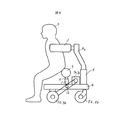
【解決手段】歩行支援装置1は、台板16と、力センサを内蔵した略コの字形のサポータ3と、このサポータの上下位置を変更可能な昇降手段4と、駆動モータ7a、7bの動力が伝動ベルト6a、6bを介して伝達される駆動車輪5a、5bと、従動車輪8a、8bとを有する。使用者2は、サポータの内側でサポータに掴まって歩行するときに、サポータの高さを昇降手段で調整する。台板に取付けた伸縮手段11にアーム10が、アームの先端に力センサを内蔵する膝当て9がそれぞれ取り付けられている。使用者は立上がるときに、両膝を膝当てに当てる。膝当てに使用者の膝が当るよう伸縮手段を用いてアーム長を変える。歩行時にアームが歩行を妨げないよう、アームを進行方向に旋回させる。
【選択図】 図1An object of the present invention is to assist walking by assisting a user in rising.
A walking support device includes a base plate, a substantially U-shaped supporter having a built-in force sensor, lifting means capable of changing the vertical position of the supporter, and power of drive motors. Has driven wheels 5a and 5b transmitted through transmission belts 6a and 6b, and driven wheels 8a and 8b. When the user 2 walks while holding the supporter inside the supporter, the user 2 adjusts the height of the supporter by the elevating means. The arm 10 is attached to the expansion / contraction means 11 attached to the base plate, and the knee pad 9 having a built-in force sensor is attached to the tip of the arm. When standing up, the user places both knees on the knee rest. The arm length is changed using a telescopic means so that the user's knee hits the knee pad. The arm is turned in the traveling direction so that the arm does not hinder walking when walking.
[Selection diagram] Fig. 1
Description
【0001】
【発明の属する技術分野】
本発明は、使用者の歩行を支援する歩行支援装置に関する。
【0002】
【従来の技術】
筋力等の身体機能が低下した高齢者や障害者の身体活動を支援する装置の例が、特許文献1に記載されている。この公報に記載の姿勢変換装置は、自力で立上がることが困難な患者の立上がりを補助するために、膝パッドで患者の膝を支えるとともに胸パッドで患者の胸を支えている。これにより、患者を前傾姿勢にして立上がらせている。その際、上半身と臀部を支持するサポート部材やベルト付きの脇パッドを用いて、患者の胸を胸パッドに押し当てている。
【特許文献1】
特開平9−570号公報(第4〜11頁、第1図)
【0003】
【発明が解決しようとする課題】
自分で立位姿勢を保持できる程度の筋力を有する患者でも、椅子などに座った状態から立上がるときには、足に加わる負担が大きい。そこで、他人等が患者の膝を支持して、立ち上がりを容易にすることが上記特許文献1等で提案されている。しかしながらこの特許文献1では、患者の身体をサポート部材やベルト付きの脇パッドを用いて支持しているので、患者は身体を自由に動かせないという不具合がある。また、膝パッドが常に患者の足の前に位置するので、歩行するのに膝パッドが妨げとなり、立上がった患者がすぐに歩行することが困難であった。
【0004】
本発明の目的は、筋力等の身体機能が低下した高齢者や障害者の負担を軽減して座った状態からの立上がりと立上がった後の歩行を歩行支援装置が支援できるようにするこにある。
【0005】
【課題を解決するための手段】
上記目的を達成する本発明の特徴は、使用者の身体を支える支持手段と、使用者の歩行を補助する移動手段とを有する歩行支援装置において、移動手段を制動する制動装置と、膝当てを有するアームと、このアームの長さを可変する伸縮手段と、アームを旋回させる旋回手段と、伸縮手段と旋回手段を制御する制御手段とを設けたものである。
【0006】
そしてこの特徴において、アームは使用者の膝から膝当てに作用する力を検出する力検出手段を有し、制御手段はこの力検出手段が検出した力の大きさに応じてアームの位置を制御するのが望ましく、アームの長さと旋回角度を変更させる操作手段を有するこようにしてもよい。また、制御装置は操作手段からの指令に基いて、使用者が歩行中はアームを退避位置に位置付け、使用者が起立するときは膝当てを使用者の座る位置に移動させることが望ましい。そして、記膝当てが円筒状であるのがよい。
【0007】
【発明の実施の形態】
以下、本発明に係る歩行支援装置の一実施例を、図面を用いて説明する。図1は、歩行支援装置の側面図であり、図2はその上面図である。歩行支援装置1は筋力等の身体機能が低下した使用者2の歩行を支援する装置である。台板16の上面には、詳細を後述するステー4aが、昇降手段4を介して取付けられている。台板16の下面には、一対の駆動車輪5a,5bが使用者2側に、一対の従動車輪8a,8bが反使用者2側にそれぞれ取付けられている。ステー4aの上端部近傍には、力センサを内蔵するサポータ3が取付けられている。
【0008】
図2に示すように、サポータ3は略コの字形をしている。使用者2はコの字の内側に居てサポータ3に掴まって歩行する。使用者2の歩行姿勢に合わせて、サポータ3の高さを変更する。高さの変更には、昇降手段4を用いる。左右の駆動車輪5a、5bは、それぞれ伝動ベルト6a、6bを介して駆動モータ7a、7bに接続されている。従動車輪8a、8bは、進行方向が回転自在に台板16に取り付けられている。
【0009】
昇降手段4には、ボールスクリューを用いた直動アクチュエータを用いている。ボールスクリューのボールねじの回転を制御して、直動アクチュエータに接続したサポータ3の高さを変更する。ボールねじの回転を停止して、サポータ3の高さを固定する。
【0010】
力センサを内蔵した円筒状の膝当て9が、アーム10に取り付けられている。使用者2は、立上がるときに両膝を膝当て9に当てる。膝当て9は、柔軟性のある素材のものが望ましい。膝当て9が使用者2の膝に当るように、伸縮手段11を用いてアーム10の長さを変更する。また、旋回手段12を用いてアーム10を旋回させ、使用者2の膝に膝当て9を位置させる。伸縮手段11には、ボールスクリューを有する直動アクチュエータを用いている。ボールスクリューのボールねじの回転を制御して直動アクチュエータに接続したアーム10の長さを変更する。ボールねじの回転を停止させればアーム10の長さを固定できる。
【0011】
旋回手段12には、ブレーキ付きの回転モータを用いている。モータの回転を制御してアーム10の旋回方向位置を変更する。モータを回転させる時にはブレーキを解除する。モータを停止させる時にはブレーキを作動させてアーム10の旋回方向位置を固定する。このように、伸縮手段11と旋回手段12とを用いることにより、アーム10を設定した位置で、使用者2から膝当て9に加わる力を確実に支えることができる。
【0012】
図1に示した実施例の歩行支援装置の上面図を、図2に示す。駆動車輪5a、5bを制動するブレーキ13a、13bが、駆動モータ7a、7bに取付けられている。駆動モータ7a、7bには、この駆動モータ7a、7bの回転を検出する回転センサ14a、14bが軸端部に取付けられている。コントローラ15は、各力センサを用いて計測するとともに、昇降手段4や駆動モータ7a、bを制御する。また、伸縮手段11と旋回手段12を用いてアーム10を制御する。
【0013】
図2に示した歩行支援装置が有する操作手段20の詳細を、図3に示す。操作手段20は、歩行支援装置本体のコントローラ15に有線または無線で接続されている。使用者2は、動作ボタン21を用いて動作を選択する。操作手段20には、サポータ3の位置を操作するためのサポータ操作ボタン22と、アーム10の位置を操作するためのアーム操作ボタン23とを備えている。使用者2が操作手段の各ボタンを操作すると、コントローラ15が歩行支援装置1とサポータ3とアーム10を制御する。
【0014】
このように構成した歩行支援装置の動作を、図4の処理フローを用いて説明する。使用者2が、動作ボタン21中の起立ボタンを選択すると、コントローラ15はブレーキ13a、13bを制御して駆動車輪5a、5bを制動する。そして、膝当て9が使用者2の膝に当るようにアーム10を所定の位置に移動させ、その位置で位置固定する(ステップ100)。
【0015】
膝当て9が使用者2の膝に当ると、使用者2はサポータ3を掴んで立上がる(ステップ101)。このとき、コントローラ15は、膝当て9に内蔵した力センサで使用者2の膝が膝当て9を押す力を計測する。使用者2が立上がってしまえば、使用者2の膝を膝当て9で支持する必要がなくなる。使用者2が立ち上がった状態では膝当て9に作用する力が小さくなる。そこで、膝当てに作用する力が所定の値以下になったら使用者2が立上がったものと判断し、アーム10位置の固定を解除しアーム10を昇降手段4側の所定の位置に移動させる。所定位置に到達したら、アーム10の位置を固定する(ステップ102)。
【0016】
アーム10が昇降手段4側に移動した状態を、図5に示す。アーム10を昇降手段4側に旋回させたので、アーム10が使用者2の歩行を妨げるのを回避できる。このため、使用者2は立上がったらすぐにサポータ3の内側に入り、サポータ3に掴まって歩行することができる。
【0017】
使用者2は、立上がって操作手段20の動作ボタン21から歩行を選択する。そして、サポータ3に掴まって歩行を開始する(ステップ103)。このとき、コントローラ15は、ブレーキ13a、13bを制御して駆動車輪5a、5bの制動を解除する。それとともに、サポータ3に内蔵した力センサに使用者2から加わる力を計測する。そして、力が作用する方向に歩行支援装置1を移動させるために、駆動車輪5a、5bを駆動する駆動モータ7a、7bを制御する。
【0018】
歩行中に使用者2がその場に静止する場合は、操作手段20中の動作ボタン21から停止ボタンを選択する。停止ボタンが押されると、コントローラ15はブレーキ13a、13bを制御して駆動車輪5a、5bを制動する。使用者2がその場で少し休憩する場合は、動作ボタン21中の休憩ボタンを選択する(ステップ104)。休憩ボタンが押されると、コントローラ15はブレーキ13a、13bを制御して駆動車輪5a、5bを制動する。そして、膝当て9に使用者2が座られるようにアーム10を所定の位置に移動させる。そしてその所定位置で、アーム10の位置を固定する(ステップ105)。使用者2が座られる位置に膝当て9が移動したら、使用者2は膝当て9に座って休憩できる(ステップ106)。
【0019】
使用者2が膝当て9に着座した状態を、図6に示す。使用者2が歩行中に疲れて歩行支援装置1に着座するときは、歩行支援装置1に後ろ向きに着座する。これにより、足を自由に伸ばすことができる。また、その場での立ち仕事、例えば洗面なども行える。着座後に歩行するときは、立上がった後に進行方向に向きを変える。休憩後に使用者2が起立し(ステップ107)、さらに歩行する場合は動作ボタン21中の歩行ボタンを選択する(ステップ108)。ステップ104で休憩を選択しない場合も、ステップ108に移行する。歩行ボタンが選択されると、ステップ102に移行する。
【0020】
ステップ108で歩行ボタンが選択される間は上記を繰り返す。ステップ108で歩行ボタンが選択されないときは、コントローラ15がブレーキ13a、13bを駆動して駆動車輪5a、5bを制動する。これにより、処理は終了される。上記動作においては、アーム10が移動する位置を、予め使用者2に合わせて設定している。しかし、操作手段20中のアーム操作ボタン23を用いて、使用者の膝の位置に膝当て9の位置を調整してもよい。
【0021】
本実施例によれば、膝当てを用いて歩行者が立上がるのを補助するとともに、立上がった後に膝当てを歩行の妨げにならない位置に移動させている。したがって、使用者が自分の意志で起立と歩行を行える。また、使用者が歩行している途中で膝当てに座ることができるので使用者の移動可能空間距離が増し、より広い生活空間が得られる。
【0022】
本実施例では、膝当てを円筒状にしたが、膝当ての形状はこれに限るものではなく、角柱状でも良い。その場合、角柱の面位置を制御すれば膝当てと着座の双方に対応できる。また、使用者の両膝を1本の膝当てで支持したが、左右の膝をそれぞれ別個に支持しても良い。また、本実施例では膝当てに着座しているが、着座には限らず休憩できる状態であればよい。例えば、腰を膝当てに預けるようにしてもよい。
【0023】
なお、上記実施例は例示的なものであり、限定的なものではない。本発明の真の精神及び範囲内に存在する変形例は、すべて特許請求の範囲に含まれる。
【0024】
【発明の効果】
本発明によれば、立上がりから歩行への動作に応じてアーム位置を変更するようにしたので、身体機能が低下した高齢者や障害者の負担を軽減して座った状態からの立上がりと立上がった後の歩行の動作を歩行支援装置が支援できる。これにより、使用者が生活空間内で自分の身体能力に応じて自立して移動することができる。
【図面の簡単な説明】
【図1】本発明に係る歩行支援装置の一実施例の歩行支援装置の側面図。
【図2】図1に示した歩行支援装置の上面図。
【図3】図1に示した歩行支援装置に用いられる操作手段の正面図。
【図4】図1に示した歩行支援装置における処理フローを示す図。
【図5】図1に示した歩行支援装置の歩行時の状態を説明する側面図。
【図6】図5に示した歩行支援装置の着座時の状態を説明する側面図。
【符号の説明】
1…歩行支援装置、2…使用者、3…サポータ、4…昇降手段、5a、5b…駆動車輪、6a、6b…伝動ベルト、7a、7b…駆動モータ、8a、8b…従動車輪、9…膝当て、10…アーム、11…伸縮手段、12…旋回手段、13a、13b…ブレーキ、14a、14b…回転センサ、15…コントローラ、16…台板、20…操作手段、21…動作ボタン、22…サポータ操作ボタン、23…アーム操作ボタン。[0001]
TECHNICAL FIELD OF THE INVENTION
The present invention relates to a walking support device that supports a user's walking.
[0002]
[Prior art]
[Patent Document 1]
JP-A-9-570 (pages 4 to 11, FIG. 1)
[0003]
[Problems to be solved by the invention]
Even if the patient has enough muscular strength to be able to maintain his or her standing posture, the burden on his / her feet is great when standing up from a state of sitting on a chair or the like. Therefore, it has been proposed in
[0004]
SUMMARY OF THE INVENTION An object of the present invention is to reduce the burden on the elderly and disabled people whose physical functions such as muscular strength are reduced, and to enable the walking support device to support rising from a sitting state and walking after the rising. is there.
[0005]
[Means for Solving the Problems]
A feature of the present invention that achieves the above object is that in a walking assistance device having support means for supporting a user's body and moving means for assisting the user's walking, a braking device for braking the moving means, and a knee pad are provided. Arm, a telescopic means for varying the length of the arm, a turning means for turning the arm, and a control means for controlling the telescopic means and the turning means.
[0006]
In this feature, the arm has force detecting means for detecting a force acting on the user's knee from the knee, and the control means controls the position of the arm according to the magnitude of the force detected by the force detecting means. It is desirable to have an operating means for changing the length and the turning angle of the arm. Further, it is desirable that the control device, based on a command from the operating means, position the arm at the retreat position while the user is walking, and move the knee pad to a position where the user sits when the user stands up. The knee pad is preferably cylindrical.
[0007]
BEST MODE FOR CARRYING OUT THE INVENTION
Hereinafter, an embodiment of a walking support device according to the present invention will be described with reference to the drawings. FIG. 1 is a side view of the walking support device, and FIG. 2 is a top view thereof. The
[0008]
As shown in FIG. 2, the
[0009]
A linear motion actuator using a ball screw is used as the elevating means 4. The height of the
[0010]
A
[0011]
For the turning means 12, a rotary motor with a brake is used. The rotation of the
[0012]
FIG. 2 shows a top view of the walking support device of the embodiment shown in FIG.
[0013]
FIG. 3 shows details of the operation means 20 included in the walking support device shown in FIG. The
[0014]
The operation of the walking assistance device thus configured will be described with reference to the processing flow of FIG. When the user 2 selects the standing button among the operation buttons 21, the
[0015]
When the
[0016]
FIG. 5 shows a state in which the
[0017]
The user 2 stands up and selects walking from the operation button 21 of the operation means 20. Then, the user grasps the
[0018]
When the user 2 stops at the place while walking, the user selects a stop button from the operation buttons 21 in the operation means 20. When the stop button is pressed, the
[0019]
FIG. 6 shows a state where the user 2 is seated on the
[0020]
The above is repeated while the walk button is selected in step 108. If the walk button is not selected in step 108, the
[0021]
According to the present embodiment, the pedestrian is assisted to stand up by using the knee rest, and the knee rest is moved to a position that does not hinder walking after standing up. Therefore, the user can stand and walk on his own will. In addition, since the user can sit on the lap while walking, the movable space distance of the user can be increased, and a wider living space can be obtained.
[0022]
In the present embodiment, the knee pad is cylindrical, but the shape of the knee pad is not limited to this, and may be a prismatic shape. In this case, by controlling the surface position of the prism, it is possible to cope with both knee rest and sitting. Further, although both knees of the user are supported by one knee pad, the left and right knees may be separately supported. Further, in the present embodiment, the user sits on the knee pad, but the present invention is not limited to sitting on the knee but may be any state in which the user can take a break. For example, the waist may be left on the knee pad.
[0023]
In addition, the said Example is an illustration and is not restrictive. All modifications that come within the true spirit and scope of the invention are included in the following claims.
[0024]
【The invention's effect】
According to the present invention, since the arm position is changed according to the operation from rising to walking, the rising and rising from the sitting state is reduced by reducing the burden on the elderly and the disabled with reduced physical function. The walking support device can support the walking operation after the walking. Thereby, the user can move independently in the living space according to his / her physical ability.
[Brief description of the drawings]
FIG. 1 is a side view of a walking support device according to an embodiment of the present invention.
FIG. 2 is a top view of the walking support device shown in FIG. 1;
FIG. 3 is a front view of operating means used in the walking support device shown in FIG. 1;
FIG. 4 is a view showing a processing flow in the walking support device shown in FIG. 1;
FIG. 5 is a side view illustrating a state of the walking support device shown in FIG. 1 during walking.
FIG. 6 is a side view for explaining a state of the walking support device shown in FIG. 5 when seated.
[Explanation of symbols]
DESCRIPTION OF
Claims (6)
Priority Applications (1)
| Application Number | Priority Date | Filing Date | Title |
|---|---|---|---|
| JP2002290577A JP4115798B2 (en) | 2002-10-03 | 2002-10-03 | Walking support device |
Applications Claiming Priority (1)
| Application Number | Priority Date | Filing Date | Title |
|---|---|---|---|
| JP2002290577A JP4115798B2 (en) | 2002-10-03 | 2002-10-03 | Walking support device |
Publications (2)
| Publication Number | Publication Date |
|---|---|
| JP2004121569A true JP2004121569A (en) | 2004-04-22 |
| JP4115798B2 JP4115798B2 (en) | 2008-07-09 |
Family
ID=32282391
Family Applications (1)
| Application Number | Title | Priority Date | Filing Date |
|---|---|---|---|
| JP2002290577A Expired - Fee Related JP4115798B2 (en) | 2002-10-03 | 2002-10-03 | Walking support device |
Country Status (1)
| Country | Link |
|---|---|
| JP (1) | JP4115798B2 (en) |
Cited By (4)
| Publication number | Priority date | Publication date | Assignee | Title |
|---|---|---|---|---|
| JP2013529498A (en) * | 2010-06-23 | 2013-07-22 | ゲート リハブ ディベロプメント エービー | Standing support built into the walker |
| US8690801B2 (en) | 2010-06-21 | 2014-04-08 | Toyota Jidosha Kabushiki Kaisha | Leg assist device |
| JP2017104972A (en) * | 2015-12-02 | 2017-06-15 | パナソニックIpマネジメント株式会社 | Robot, robot control method, and program |
| CN112535616A (en) * | 2020-11-25 | 2021-03-23 | 哈尔滨工业大学 | Stair climbing type walking-aid robot |
Citations (2)
| Publication number | Priority date | Publication date | Assignee | Title |
|---|---|---|---|---|
| JPH10192344A (en) * | 1997-01-10 | 1998-07-28 | Japan Steel Works Ltd:The | Assistance transfer device |
| JP2001008982A (en) * | 1999-06-26 | 2001-01-16 | Data Tecno:Kk | Supporting device |
-
2002
- 2002-10-03 JP JP2002290577A patent/JP4115798B2/en not_active Expired - Fee Related
Patent Citations (2)
| Publication number | Priority date | Publication date | Assignee | Title |
|---|---|---|---|---|
| JPH10192344A (en) * | 1997-01-10 | 1998-07-28 | Japan Steel Works Ltd:The | Assistance transfer device |
| JP2001008982A (en) * | 1999-06-26 | 2001-01-16 | Data Tecno:Kk | Supporting device |
Cited By (4)
| Publication number | Priority date | Publication date | Assignee | Title |
|---|---|---|---|---|
| US8690801B2 (en) | 2010-06-21 | 2014-04-08 | Toyota Jidosha Kabushiki Kaisha | Leg assist device |
| JP2013529498A (en) * | 2010-06-23 | 2013-07-22 | ゲート リハブ ディベロプメント エービー | Standing support built into the walker |
| JP2017104972A (en) * | 2015-12-02 | 2017-06-15 | パナソニックIpマネジメント株式会社 | Robot, robot control method, and program |
| CN112535616A (en) * | 2020-11-25 | 2021-03-23 | 哈尔滨工业大学 | Stair climbing type walking-aid robot |
Also Published As
| Publication number | Publication date |
|---|---|
| JP4115798B2 (en) | 2008-07-09 |
Similar Documents
| Publication | Publication Date | Title |
|---|---|---|
| US9161871B2 (en) | Multiple function patient handling devices and methods | |
| CN108778633B (en) | Stand up and walk assist robot | |
| JP2018511452A (en) | Patient transport and training aids | |
| JP2002224174A (en) | Stand-up lift | |
| KR101748140B1 (en) | automatic moving type walking traning device | |
| KR101219305B1 (en) | Auxiliary platform for walking | |
| JP4630119B2 (en) | Transfer support device | |
| JP3792481B2 (en) | Walking assist device | |
| WO2014029988A1 (en) | Leg lifter apparatus | |
| TW200305379A (en) | Coordinative lifting control method of bottom sections for lying furniture such as a bed | |
| KR20160129986A (en) | Stand up assistance equipment | |
| KR20180123792A (en) | Walking assistance device for helping standing up and sitting down and monitoring system for the same | |
| JP4115798B2 (en) | Walking support device | |
| KR101986269B1 (en) | Stand-up walking aids | |
| JP2003265558A (en) | Violent tumble preventing walking vehicle | |
| JP2714617B2 (en) | Walking bending and stretching motion assist device | |
| JP6233057B2 (en) | Nursing care support device | |
| JP4240585B2 (en) | Massage chair with seat lift | |
| JP2017000190A (en) | Motion support device | |
| KR20180123995A (en) | Walking assistance device for helping standing up and sitting down | |
| KR101662013B1 (en) | Electric walking adds device | |
| JPH10192346A (en) | Transfer machine | |
| JP4184509B2 (en) | Lower limb training equipment | |
| JP3955362B2 (en) | Walking support machine | |
| WO2005053593A1 (en) | Apparatus and method for displacing persons from a sitting to a standing position |
Legal Events
| Date | Code | Title | Description |
|---|---|---|---|
| A621 | Written request for application examination |
Free format text: JAPANESE INTERMEDIATE CODE: A621 Effective date: 20050413 |
|
| RD01 | Notification of change of attorney |
Free format text: JAPANESE INTERMEDIATE CODE: A7421 Effective date: 20060420 |
|
| RD01 | Notification of change of attorney |
Free format text: JAPANESE INTERMEDIATE CODE: A7421 Effective date: 20071119 |
|
| A131 | Notification of reasons for refusal |
Free format text: JAPANESE INTERMEDIATE CODE: A131 Effective date: 20080122 |
|
| A521 | Written amendment |
Free format text: JAPANESE INTERMEDIATE CODE: A523 Effective date: 20080317 |
|
| TRDD | Decision of grant or rejection written | ||
| A01 | Written decision to grant a patent or to grant a registration (utility model) |
Free format text: JAPANESE INTERMEDIATE CODE: A01 Effective date: 20080415 |
|
| A61 | First payment of annual fees (during grant procedure) |
Free format text: JAPANESE INTERMEDIATE CODE: A61 Effective date: 20080416 |
|
| FPAY | Renewal fee payment (event date is renewal date of database) |
Free format text: PAYMENT UNTIL: 20110425 Year of fee payment: 3 |
|
| R150 | Certificate of patent or registration of utility model |
Free format text: JAPANESE INTERMEDIATE CODE: R150 |
|
| FPAY | Renewal fee payment (event date is renewal date of database) |
Free format text: PAYMENT UNTIL: 20110425 Year of fee payment: 3 |
|
| FPAY | Renewal fee payment (event date is renewal date of database) |
Free format text: PAYMENT UNTIL: 20120425 Year of fee payment: 4 |
|
| FPAY | Renewal fee payment (event date is renewal date of database) |
Free format text: PAYMENT UNTIL: 20120425 Year of fee payment: 4 |
|
| FPAY | Renewal fee payment (event date is renewal date of database) |
Free format text: PAYMENT UNTIL: 20130425 Year of fee payment: 5 |
|
| FPAY | Renewal fee payment (event date is renewal date of database) |
Free format text: PAYMENT UNTIL: 20130425 Year of fee payment: 5 |
|
| FPAY | Renewal fee payment (event date is renewal date of database) |
Free format text: PAYMENT UNTIL: 20140425 Year of fee payment: 6 |
|
| LAPS | Cancellation because of no payment of annual fees |