EP3852644B1 - Medical occlusion device - Google Patents
Medical occlusion device Download PDFInfo
- Publication number
- EP3852644B1 EP3852644B1 EP19862977.6A EP19862977A EP3852644B1 EP 3852644 B1 EP3852644 B1 EP 3852644B1 EP 19862977 A EP19862977 A EP 19862977A EP 3852644 B1 EP3852644 B1 EP 3852644B1
- Authority
- EP
- European Patent Office
- Prior art keywords
- balloon
- occlusion device
- proximal
- distal tip
- distal
- Prior art date
- Legal status (The legal status is an assumption and is not a legal conclusion. Google has not performed a legal analysis and makes no representation as to the accuracy of the status listed.)
- Active
Links
Images


Classifications
-
- A—HUMAN NECESSITIES
- A61—MEDICAL OR VETERINARY SCIENCE; HYGIENE
- A61B—DIAGNOSIS; SURGERY; IDENTIFICATION
- A61B17/00—Surgical instruments, devices or methods
- A61B17/12—Surgical instruments, devices or methods for ligaturing or otherwise compressing tubular parts of the body, e.g. blood vessels or umbilical cord
- A61B17/12022—Occluding by internal devices, e.g. balloons or releasable wires
- A61B17/12131—Occluding by internal devices, e.g. balloons or releasable wires characterised by the type of occluding device
- A61B17/12136—Balloons
-
- A—HUMAN NECESSITIES
- A61—MEDICAL OR VETERINARY SCIENCE; HYGIENE
- A61B—DIAGNOSIS; SURGERY; IDENTIFICATION
- A61B17/00—Surgical instruments, devices or methods
- A61B17/0057—Implements for plugging an opening in the wall of a hollow or tubular organ, e.g. for sealing a vessel puncture or closing a cardiac septal defect
-
- A—HUMAN NECESSITIES
- A61—MEDICAL OR VETERINARY SCIENCE; HYGIENE
- A61B—DIAGNOSIS; SURGERY; IDENTIFICATION
- A61B17/00—Surgical instruments, devices or methods
- A61B17/12—Surgical instruments, devices or methods for ligaturing or otherwise compressing tubular parts of the body, e.g. blood vessels or umbilical cord
- A61B17/12022—Occluding by internal devices, e.g. balloons or releasable wires
- A61B17/12099—Occluding by internal devices, e.g. balloons or releasable wires characterised by the location of the occluder
- A61B17/12122—Occluding by internal devices, e.g. balloons or releasable wires characterised by the location of the occluder within the heart
-
- A—HUMAN NECESSITIES
- A61—MEDICAL OR VETERINARY SCIENCE; HYGIENE
- A61B—DIAGNOSIS; SURGERY; IDENTIFICATION
- A61B17/00—Surgical instruments, devices or methods
- A61B17/12—Surgical instruments, devices or methods for ligaturing or otherwise compressing tubular parts of the body, e.g. blood vessels or umbilical cord
- A61B17/12022—Occluding by internal devices, e.g. balloons or releasable wires
- A61B17/12131—Occluding by internal devices, e.g. balloons or releasable wires characterised by the type of occluding device
- A61B17/12168—Occluding by internal devices, e.g. balloons or releasable wires characterised by the type of occluding device having a mesh structure
- A61B17/12172—Occluding by internal devices, e.g. balloons or releasable wires characterised by the type of occluding device having a mesh structure having a pre-set deployed three-dimensional shape
-
- A—HUMAN NECESSITIES
- A61—MEDICAL OR VETERINARY SCIENCE; HYGIENE
- A61F—FILTERS IMPLANTABLE INTO BLOOD VESSELS; PROSTHESES; DEVICES PROVIDING PATENCY TO, OR PREVENTING COLLAPSING OF, TUBULAR STRUCTURES OF THE BODY, e.g. STENTS; ORTHOPAEDIC, NURSING OR CONTRACEPTIVE DEVICES; FOMENTATION; TREATMENT OR PROTECTION OF EYES OR EARS; BANDAGES, DRESSINGS OR ABSORBENT PADS; FIRST-AID KITS
- A61F2/00—Filters implantable into blood vessels; Prostheses, i.e. artificial substitutes or replacements for parts of the body; Appliances for connecting them with the body; Devices providing patency to, or preventing collapsing of, tubular structures of the body, e.g. stents
- A61F2/02—Prostheses implantable into the body
- A61F2/24—Heart valves ; Vascular valves, e.g. venous valves; Heart implants, e.g. passive devices for improving the function of the native valve or the heart muscle; Transmyocardial revascularisation [TMR] devices; Valves implantable in the body
- A61F2/2412—Heart valves ; Vascular valves, e.g. venous valves; Heart implants, e.g. passive devices for improving the function of the native valve or the heart muscle; Transmyocardial revascularisation [TMR] devices; Valves implantable in the body with soft flexible valve members, e.g. tissue valves shaped like natural valves
- A61F2/2418—Scaffolds therefor, e.g. support stents
-
- A—HUMAN NECESSITIES
- A61—MEDICAL OR VETERINARY SCIENCE; HYGIENE
- A61B—DIAGNOSIS; SURGERY; IDENTIFICATION
- A61B17/00—Surgical instruments, devices or methods
- A61B17/12—Surgical instruments, devices or methods for ligaturing or otherwise compressing tubular parts of the body, e.g. blood vessels or umbilical cord
- A61B17/122—Clamps or clips, e.g. for the umbilical cord
- A61B17/1227—Spring clips
-
- A—HUMAN NECESSITIES
- A61—MEDICAL OR VETERINARY SCIENCE; HYGIENE
- A61B—DIAGNOSIS; SURGERY; IDENTIFICATION
- A61B17/00—Surgical instruments, devices or methods
- A61B2017/00367—Details of actuation of instruments, e.g. relations between pushing buttons, or the like, and activation of the tool, working tip, or the like
- A61B2017/00407—Ratchet means
-
- A—HUMAN NECESSITIES
- A61—MEDICAL OR VETERINARY SCIENCE; HYGIENE
- A61B—DIAGNOSIS; SURGERY; IDENTIFICATION
- A61B17/00—Surgical instruments, devices or methods
- A61B2017/0046—Surgical instruments, devices or methods with a releasable handle; with handle and operating part separable
- A61B2017/00473—Distal part, e.g. tip or head
-
- A—HUMAN NECESSITIES
- A61—MEDICAL OR VETERINARY SCIENCE; HYGIENE
- A61B—DIAGNOSIS; SURGERY; IDENTIFICATION
- A61B17/00—Surgical instruments, devices or methods
- A61B2017/00535—Surgical instruments, devices or methods pneumatically or hydraulically operated
- A61B2017/00557—Surgical instruments, devices or methods pneumatically or hydraulically operated inflatable
-
- A—HUMAN NECESSITIES
- A61—MEDICAL OR VETERINARY SCIENCE; HYGIENE
- A61B—DIAGNOSIS; SURGERY; IDENTIFICATION
- A61B17/00—Surgical instruments, devices or methods
- A61B17/0057—Implements for plugging an opening in the wall of a hollow or tubular organ, e.g. for sealing a vessel puncture or closing a cardiac septal defect
- A61B2017/00575—Implements for plugging an opening in the wall of a hollow or tubular organ, e.g. for sealing a vessel puncture or closing a cardiac septal defect for closure at remote site, e.g. closing atrial septum defects
- A61B2017/00592—Elastic or resilient implements
-
- A—HUMAN NECESSITIES
- A61—MEDICAL OR VETERINARY SCIENCE; HYGIENE
- A61B—DIAGNOSIS; SURGERY; IDENTIFICATION
- A61B17/00—Surgical instruments, devices or methods
- A61B17/0057—Implements for plugging an opening in the wall of a hollow or tubular organ, e.g. for sealing a vessel puncture or closing a cardiac septal defect
- A61B2017/00575—Implements for plugging an opening in the wall of a hollow or tubular organ, e.g. for sealing a vessel puncture or closing a cardiac septal defect for closure at remote site, e.g. closing atrial septum defects
- A61B2017/00597—Implements comprising a membrane
-
- A—HUMAN NECESSITIES
- A61—MEDICAL OR VETERINARY SCIENCE; HYGIENE
- A61B—DIAGNOSIS; SURGERY; IDENTIFICATION
- A61B17/00—Surgical instruments, devices or methods
- A61B17/0057—Implements for plugging an opening in the wall of a hollow or tubular organ, e.g. for sealing a vessel puncture or closing a cardiac septal defect
- A61B2017/00575—Implements for plugging an opening in the wall of a hollow or tubular organ, e.g. for sealing a vessel puncture or closing a cardiac septal defect for closure at remote site, e.g. closing atrial septum defects
- A61B2017/00606—Implements H-shaped in cross-section, i.e. with occluders on both sides of the opening
-
- A—HUMAN NECESSITIES
- A61—MEDICAL OR VETERINARY SCIENCE; HYGIENE
- A61B—DIAGNOSIS; SURGERY; IDENTIFICATION
- A61B17/00—Surgical instruments, devices or methods
- A61B17/0057—Implements for plugging an opening in the wall of a hollow or tubular organ, e.g. for sealing a vessel puncture or closing a cardiac septal defect
- A61B2017/00575—Implements for plugging an opening in the wall of a hollow or tubular organ, e.g. for sealing a vessel puncture or closing a cardiac septal defect for closure at remote site, e.g. closing atrial septum defects
- A61B2017/00619—Locking means for locking the implement in expanded state
-
- A—HUMAN NECESSITIES
- A61—MEDICAL OR VETERINARY SCIENCE; HYGIENE
- A61B—DIAGNOSIS; SURGERY; IDENTIFICATION
- A61B17/00—Surgical instruments, devices or methods
- A61B17/0057—Implements for plugging an opening in the wall of a hollow or tubular organ, e.g. for sealing a vessel puncture or closing a cardiac septal defect
- A61B2017/00575—Implements for plugging an opening in the wall of a hollow or tubular organ, e.g. for sealing a vessel puncture or closing a cardiac septal defect for closure at remote site, e.g. closing atrial septum defects
- A61B2017/00623—Introducing or retrieving devices therefor
-
- A—HUMAN NECESSITIES
- A61—MEDICAL OR VETERINARY SCIENCE; HYGIENE
- A61B—DIAGNOSIS; SURGERY; IDENTIFICATION
- A61B17/00—Surgical instruments, devices or methods
- A61B17/0057—Implements for plugging an opening in the wall of a hollow or tubular organ, e.g. for sealing a vessel puncture or closing a cardiac septal defect
- A61B2017/00575—Implements for plugging an opening in the wall of a hollow or tubular organ, e.g. for sealing a vessel puncture or closing a cardiac septal defect for closure at remote site, e.g. closing atrial septum defects
- A61B2017/00632—Occluding a cavity, i.e. closing a blind opening
-
- A—HUMAN NECESSITIES
- A61—MEDICAL OR VETERINARY SCIENCE; HYGIENE
- A61B—DIAGNOSIS; SURGERY; IDENTIFICATION
- A61B17/00—Surgical instruments, devices or methods
- A61B2017/00743—Type of operation; Specification of treatment sites
- A61B2017/00778—Operations on blood vessels
- A61B2017/00783—Valvuloplasty
-
- A—HUMAN NECESSITIES
- A61—MEDICAL OR VETERINARY SCIENCE; HYGIENE
- A61B—DIAGNOSIS; SURGERY; IDENTIFICATION
- A61B17/00—Surgical instruments, devices or methods
- A61B17/12—Surgical instruments, devices or methods for ligaturing or otherwise compressing tubular parts of the body, e.g. blood vessels or umbilical cord
- A61B17/12022—Occluding by internal devices, e.g. balloons or releasable wires
- A61B2017/1205—Introduction devices
-
- A—HUMAN NECESSITIES
- A61—MEDICAL OR VETERINARY SCIENCE; HYGIENE
- A61F—FILTERS IMPLANTABLE INTO BLOOD VESSELS; PROSTHESES; DEVICES PROVIDING PATENCY TO, OR PREVENTING COLLAPSING OF, TUBULAR STRUCTURES OF THE BODY, e.g. STENTS; ORTHOPAEDIC, NURSING OR CONTRACEPTIVE DEVICES; FOMENTATION; TREATMENT OR PROTECTION OF EYES OR EARS; BANDAGES, DRESSINGS OR ABSORBENT PADS; FIRST-AID KITS
- A61F2250/00—Special features of prostheses classified in groups A61F2/00 - A61F2/26 or A61F2/82 or A61F9/00 or A61F11/00 or subgroups thereof
- A61F2250/0058—Additional features; Implant or prostheses properties not otherwise provided for
- A61F2250/0069—Sealing means
Definitions
- the present invention generally relates to an occlusion device for occluding a cardiovascular defect or a gap between a medical device and adjacent body tissue and a system comprising the occlusion device and a delivery system cooperating therewith.
- WO 95/32018 describes a method and a device for blocking a body passageway by inserting an expandable frame into the passageway and expanding the frame with an expandable balloon to partially embed the frame in the walls of the passageway.
- the frame can be provided with a separate sealing membrane, or the balloon can function as the sealing membrane.
- the balloon can be removed along with the inflation tube after the expansion step if it is not serving as the sealing membrane, or the balloon can be detached from the inflation tube and left in place, either as a sealing membrane or simply to lock the frame in place.
- the frame can be maintained in its expanded state by being plastically deformed during the expansion step.
- the expandable frame has substantially cylindrical shape and is described as being suitable, e.g., for closing a patent ductus arteriosus, in which an unwanted passageway or duct connects the aorta to the main pulmonary artery, close to the heart.
- US 4,836,204 describes a device for effecting closure of a perforation in the septum of the heart.
- the device comprises a double-balloon septal defect occlusion catheter which is to be inserted such that the two initially deflated balloons are positioned on opposing sides of the septum. Upon inflating, the balloons snugly engage the respective septum wall sections and thereby prevent leakage through the perforation.
- Paravalvular leak is a common complication that occurs in up to 30% of patients undergoing implantation of either surgical or transcatheter prostheses.
- the option to treat these defects percutaneously may offers safer solution for high-risk patients, without exposing them to risk related to open heart reoperation.
- the currently used devices are suboptimal since they have not been specifically developed with this intended use.
- paravalvular leak closure is generally accomplished with devices originally designed for occlusion of congenital heart defects. They are usually implanted in a low-flow environment such as patent foramen ovale or atrial septum defect, and in simple geometries.
- paravalvular leaks develop in high pressure and flow environment, and they are characterized by complex geometry. The defect is often crescent or oval shaped, which may include a tubular section with several deformities, and the structure is marginally compliant at best.
- LAA left atrial appendage
- Percutaneous LAA occlusion is a therapy for the prevention of stroke in patients with atrial fibrillation.
- LAA occlusion is used as an alternative to, or in combination with, oral anticoagulant therapy.
- LAA occlusion has favorable clinical outcomes, but commercially-available devices are typically self-expandable, and not designed to adapt to the anatomy, thus sometimes resulting in complications or suboptimal outcomes. In these environments, some of the currently available occlusion devices are limited by the poor adaptability of the device to the defect (lack of conformability) and by a lack of intra-device sealing (due to the high flow environment).
- US 2014/0277426 A1 describes various devices for occluding a gap between a medical device and adjacent body tissue.
- the devices generally comprise a conformable body with a hollow interior and provided with a fluid port intended to supply a pressurizing fluid to inflate the conformable body.
- Various shapes and constitutions of the conformable body, delivery means and fixing means are described.
- US 7,628,805 generally describes a multitude of concepts for locating and for repairing paravalvular leaks.
- the concepts include sealing stents and also multicomponent and radiation-cured adhesive compounds.
- US 2012/078295 describes an occluder device for closing a passage in a circulatory system.
- the device comprises an expandable fixation unit for fixing the occluder on the passage, which is achieved by switching between a compact form and an expanded form.
- EP 1974685 discloses a medical retainer capable of independently controlling supplying air and water to a hollow organ like a stomach and a lumen of a small intestine.
- US 3834394 discloses a method of effecting the occlusion of a blood vessel by forming an access opening in the body of the patient communicating with the desired blood vessel, introducing an occlusion member in the vessel, moving the member to the desired point of occlusion, and thereat expanding the member to a size greater than the diameter of the vessel whereby the member is substantially immovably retained therein.
- a medical device for reducing the volume of a left atrial appendage may include an elongate shaft having a distal portion, and a volume-reducing means expandable from a collapsed to an expanded state, the volume-reducing means being releasably attached to the distal portion.
- an occlusion device for occluding a cardiovascular defect or a gap between a medical device and adjacent body tissue.
- the invention is set out in the appended set of claims.
- the occlusion device is for use with a guidewire and a delivery system.
- the occlusion device comprises:
- an occlusion system comprising an occlusion device as described above and a delivery system (comprising a catheter device) cooperating therewith.
- the catheter device comprises an implant catheter tube connected to an operating handle.
- the implant catheter tube comprises a longitudinal passageway for a guidewire, a distal connection element for releasably connecting the catheter device to a correspondingly configured proximal connection element of the occlusion device, and a fluid transfer system releasably connectable to a corresponding inflation port of the occlusion device.
- the distal connection element and the proximal connection element are generally configured as cooperating members disposed, respectively, at the distal end of the catheter device and at the proximal end of the occlusion device. Examples for such cooperating members comprise cooperating threads, bayonets, or snap connections.
- Clinical indications include but are not limited to paravalvular leak (PVL), patent foramen ovale (PFO), atrial septum defect (ASD), ventricular septum defect (VSD), intravalvular leak (IVL), intraleaflet leak, leaflet perforation, type I endovascular leaks after vascular graft implant, left or right heart apex closure after transapical therapeutic access, and left atrial appendage occlusion.
- PVL paravalvular leak
- PFO patent foramen ovale
- ASD atrial septum defect
- VSD ventricular septum defect
- IVL intravalvular leak
- intraleaflet leak leaflet perforation
- type I endovascular leaks after vascular graft implant left or right heart apex closure after transapical therapeutic access
- left atrial appendage occlusion left atrial appendage occlusion.
- the occlusion device is designed to be delivered into the region to be treated in its longitudinally extended form, either entirely or partially compressed. After delivery, the occlusion device is adapted to the landing zone anatomy by inflating the balloon and subsequently shortening of the longitudinal dimension of the frame formed between the proximal base element and the distal tip element. Under the influence of internal pressure, the balloon will assume a certain volume which, for a given longitudinal frame dimension, results in a certain lateral or radial dimension, which provides a good seal between the balloon and the adjacent anatomy or implanted medical device. Changing the longitudinal frame dimension by selecting a different distance between the distal tip element and the proximal base element will lead to a corresponding change in the radial or lateral extension of the balloon.
- the lateral extension of the balloon is not necessarily symmetric, either because the balloon is not necessarily symmetric and/or because the anatomy against which the balloon is laterally expanded may cause asymmetric balloon expansion.
- the radial or lateral expansion together include within their scope one or more directions generally perpendicular to the longitudinal axis of the balloon.
- the balloon is partially inflated (e.g., to atmospheric pressure) and the longitudinal dimension of the frame is shortened; the balloon may subsequently be further inflated before release, such as if necessary to make the good seal between the balloon and the adjacent anatomy or implanted medical device.)
- distal and proximal are used accordingly to their standard meaning in the field of percutaneous cardiovascular devices.
- proximal refers to those components of the device assembly which, when following a delivery catheter during percutaneous delivery, are closer to the end of the catheter that is configured for manipulation by the user (e.g., catheter handle manipulated by a physician).
- distal is used to refer to those components of the device assembly that are more distant from the end of the catheter that is configured for manipulation by the user and/or that are inserted further into the body of a patient.
- the proximal end may face towards the left atrium and the distal end may face towards the left ventricle, when the occlusion device is deployed in the defect using a transseptal approach.
- a “compliant balloon” shall be understood as a balloon which progressively expands under the effect of increasing radial pressure as long as a certain burst pressure is not exceeded.
- strut shall be understood as an elongate structural element which can be formed e.g. as a thin wire, rod, thick-walled tube, all of which do not necessarily have a circular cross section.
- the compliant balloon of the occlusion device is not necessarily pre-shaped since the balloon, because it is compliant, takes the shape of the defect once inflated within the defect.
- the wall of the balloon has a different thickness in a specific area (e.g., centrally, such that the balloon assumes a figure-eight shape upon inflation, or longitudinally on one side, to create a backbone that causes the balloon to inflate less on that side).
- pre-shaped balloons can be used to establish a predetermined, non-uniform local resilience against an applied radial pressure.
- the balloon comprises silicone, polyurethane, polytetrafluoroethylene (PTFE), polymethylmethacrylate, polyether ether ketone (PEEK), polyvinyl chloride, polyethylene terephthalate, nylon, polyamide, polyamide, polyether block amide (PEBA), or another biocompatible material.
- the balloon comprises a compliant, biodegradable material selected from polycaprolactone (PCL), polyglycolic acid (PGA), polylactic acid (PLA), and polydioxanone (PDO or PDS).
- the balloon is treated externally with a hydrophilic coating, hydrophobic coating, an anti-inflammatory coating, anticoagulation coating, or other coating to promote endothelial growth, such as chemically or by modifying the porosity of the external surface of the balloon.
- the proximal base element and the distal tip element are connected by one or more struts.
- the struts comprise a single connecting strut disposed within the balloon lumen or outside the balloon.
- the struts comprise a plurality of struts, e.g., disposed in a cage-like manner outside the balloon. Applying internal pressure to the balloon will lead to inflation thereof against a resilient force of the compliant balloon material and also against the structural limitation provided by the plurality of external connecting struts.
- such a configuration may offer the advantage of an improved stability of the compliant balloon against unwanted local deformation. This will generally result in an improved adaptation of the occlusion device to the geometry of the defect to be occluded.
- the locking mechanism for maintaining a predetermined distance between the distal tip element and the proximal base element may also be configured in various manners.
- the locking mechanism may comprise a rotatable elongate actuating element (e.g., a wire) with a threaded portion formed to cooperate with a corresponding section formed in the proximal base element.
- the locking mechanism is configured as a ratchet mechanism such that the distance between the distal tip element and the proximal base element is selectable from a range of distances. This allows for precise and reliable definition of the radial extension of the occlusion device and accordingly to improved reliability of the occlusion device.
- the elongate actuating element is disposed longitudinally slidable in the balloon lumen, connected to the distal tip element and longitudinally slidable with respect to the proximal base element so as to set a distance between the distal tip element and the proximal base element.
- the elongate actuating element is typically formed as an elongate, flexible member with a smooth surface.
- the elongate actuating element is configured as actuating wire.
- the use of actuating wires is well established in the field of cardiovascular interventions. In the present context, the use of a wire together with appropriate proximal counterpieces allows for simple, precise and reproducible selection of the distance between the distal tip element and the proximal base element.
- the balloon has an inflation port configured as a self-closing valve when it is not connected to a corresponding fluid transfer system of the delivery system.
- this allows filling the balloon through a longitudinal fluid line which can subsequently be disconnected and retracted and which only needs to be reinserted and reconnected if an additional filling or an unfilling of the balloon is needed.
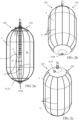
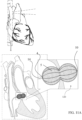
- FIG. 1a shows a cross-sectional view of an expanded occlusion device 20.
- FIGS. 1b and 1c show side elevational views of the occlusion device 20 illustrated in FIG. 1a .
- Occlusion device is for use with a guidewire 106 and a delivery system 107 (shown in FIGS. 10a-c ).
- the occlusion device 20 comprises a compliant balloon 5 having a central balloon lumen 6 forming a longitudinal passage 27 through an interior of the balloon 5 from a proximal side 28A to a distal side 28B of the balloon 5.
- the balloon 5 defines a fluid-tight balloon chamber 26.
- the balloon 5 is typically compliant, as defined above.
- the balloon lumen 6 is foldable, such that the balloon lumen 6 closes on itself after the guidewire 106 (shown in FIGS. 10a-c ) is removed, so not to leave an open passage within the occlusion device 20.
- the foldability of the balloon lumen 6 may be provided by providing proximal and distal valves on the entrances of the balloon lumen 6, or by configuring the balloon lumen 6 to collapse and fold longitudinally.
- the occlusion device 20 further comprises a frame 22 comprising a proximal base element 4 and a distal tip element 10, disposed at the proximal and distal sides 28A and 28B of the balloon 5, respectively, and connected by an elongate actuating element 9 passing and longitudinally slidable within the central lumen 6 of the balloon 5.
- the elongate actuating element 9 is longitudinally moveable with respect to the proximal base element 4 so as to set a distance between the distal tip element 10 and the proximal base element 4.
- the elongate actuating element 9 is selected from the group consisting of: a tube, a wire, a shaft, a cable, a strand, and a fiber. Reduction of the distance may cause the distal tip element 10 to move toward the proximal base element 4, the proximal base element 4 to move toward the distal tip element 10, or both movements.
- the proximal base element 4 and the distal tip element 10 comprise a proximal disk 30 and a distal disk 32, respectively.
- the frame 22 provides structural support to the balloon 5.
- the frame 22 may be formed from a cut structure so that each component of the frame 22 is integrally connected with each other.
- the elongate actuating element 9 may have a linear or nonlinear section and may have plastic or metallic deformable characteristics.
- the occlusion device 20 further comprises a locking mechanism 2 for maintaining, between the distal tip element 10 and the proximal base element 4, the distance set using the elongate actuating element 9.
- the locking mechanism 2 may comprise a crimping element, a threaded element, a locking element, an inflatable balloon, a locking wire, or a ratchet element.
- the locking mechanism 2 is disposed at the proximal side 28A of the balloon 5, for example, connected to or integrated into the proximal base element 4.
- the occlusion device 20 is shaped so as to form a closed three-dimensional shape.
- the occlusion device 20 comprises a proximal connection element 1 that is configured to attach the occlusion device 20 to and release the occlusion device 20 from delivery system 107, e.g., from an implant catheter 14 of delivery system 107. It is noted that the longitudinal passage 27 is still defined through the interior of the balloon 5 after release of the occlusion device 20 from the implant catheter 14. Typically, when the occlusion device 20 is connected to the implant catheter 14, no portion of the implant catheter 14 is disposed within the interior of the balloon 5.
- the proximal base element 4 and the distal tip element 10 are shaped so as to define respective guidewire openings 105a and 105b substantially coaxial to the balloon lumen 6 for slidingly receiving therein guidewire 106 (shown in FIGS. 10a-c ) for delivering the occlusion device 20.
- the proximal base element 4 and the distal tip element 10 are deformable, such as to allow the elements to automatically adjust their shapes upon inflation of the balloon 5.
- the proximal base element 4 and the distal tip element 10 are not deformable.
- the proximal base element 4 and the distal tip element 10 (e.g., the proximal and distal disks 30 and 32) comprise a plastic or a metal, e.g., Nitinol.
- proximal and distal disks 30 and 32 are shown as circular in the figures, the disks may have other shapes, such as the shape of a flower, a cross, a star, an ellipse, or any other shape as necessary or appropriate for proper cardiovascular defects occlusion and device stabilization.
- the proximal and distal disks 30 and 32 are typically radially symmetric, but may also be asymmetric.
- the occlusion device 20 further comprises an inflation port 3 entering into the balloon 5 along a central axis of the balloon 5 or elsewhere, such as in close vicinity of the central axis.
- the inflation port 3 is releasably connected to an inflation tube channel of the implant catheter 14 and allows inflation and deflation of the balloon 5 while connected before release of the occlusion device 20 from the implant catheter 14.
- the balloon 5 may define a guidewire lumen 7 allowing guidewire 106 (shown in FIGS. 10a-c ) to freely move axially through the occlusion device 20.
- the inflation port 3 is off-center, and vice versa.
- the compliant balloon 5 may be inflated by filling the balloon chamber 26 with any fluid, including but not limited to saline solution (optionally comprising a contrast medium), blood (e.g., autologous blood), foam, and a glue (e.g., a gel, a liquid polymer that can change its proprieties to become rigid, or a hydrogel that remains a gel or self-cures at body temperature).
- saline solution optionally comprising a contrast medium
- blood e.g., autologous blood
- foam e.g., a glue
- a gel e.g., a liquid polymer that can change its proprieties to become rigid, or a hydrogel that remains a gel or self-cures at body temperature.
- the autologous blood may be drawn from the patient during the deployment of the occlusion device 20, e.g., at a location proximal to the balloon 5 within the patient's body, or drawn from the patient outside the patient's body and filled into the balloon chamber 26 via the deployment system.
- an anti-coagulation agent may be mixed with the blood in order to delay coagulation for a while in case the balloon 5 must be retrieved; eventually the blood coagulates.
- the above-mentioned fluid provides the long-term shape setting, sealing and occluding properties of the expanded occlusion device 20.
- the balloon 5 provides the acute, i.e., immediate shape setting, sealing, and occluding properties of the expanded occlusion device 20. Therefore, for applications in which occlusion device 20 is radiopaque and is implanted in a beating heart under echocardiographic, fluoroscopic, and/or x-ray guidance, upon inflation of the balloon 5, the surgeon can immediately observe whether the defect has been occluded (by observing cessation of blood flow through the defect).
- the implant catheter 14 and the inflation port 3 may contain specific channels, valves and membranes designed to be compatible with the fluid used, including filter membranes that can be permeable to blood in the case blood is used as filling fluid of the balloon chamber 26.
- the frame 22 allows longitudinal adjustment of the balloon 5 to enhance the stability of the occlusion device 20 and to enhance occlusion of the defect.
- the frame 22 may be designed to have a limited conformability (for example, because of the thickness of the frame 22 or a material property of the frame 22), such as in order to create a tapered shape to provide asymmetrical confinement to the balloon 5, for example, tapered at the distal end, such that the balloon 5 has a pear shape when constrained by anatomy or otherwise constrained.
- the frame 22 may have a generally conical, or frustoconical shape, cylindrical shape, or any other shape as necessary or appropriate.
- the balloon 5 is configured to have limited conformability in some sections of the balloon, such as in order to create a figure-eight shape or a tapered shape, or an asymmetrical shape when expanded under inflation.
- frame 22 further comprises a single strut 21 passing inside and tapering the balloon 5 component.
- the strut 21 may or may not be fixed to the inner surface of the balloon 5 or embedded in the balloon 5, as described hereinbelow with reference to FIG. 2a .
- the strut 21 passes through the central lumen 6 of the balloon 5 (configuration not shown).
- FIGS. 2a to 9b illustrate further optional features that may be provided in conjunction with the occlusion device 20 as presented in the application of FIGS. 1a to 1c .
- Like reference numbers denominate the same or corresponding features.
- FIG. 2a shows a cross-sectional view of an expanded occlusion device 120.
- FIGS. 2b and 2c show side elevational views of the occlusion device 120 illustrated in FIG. 2a .
- Occlusion device 120 comprises a frame 122, which may comprise the proximal base element 4 and the distal tip element 10 (e.g., the proximal and distal disks 30 and 32), connected by a plurality of struts 11, which may have any suitable form, passing inside (not shown) or outside (as shown) and tapering the balloon 5 component.
- the frame 122 may comprise 2, 4, 6, 8, 10, 12 or any other suitable even or odd number of struts 11.
- the struts 11 may be disposed inside or outside the balloon 5.
- the struts 11 are not fixed to any surfaces of the balloon 5.
- the struts 11 are (a) fixed to a surface (inner or outer) of the balloon 5, (b) embedded in the wall of the balloon 5 during manufacture (such as by being cast within the wall).
- the balloon 5 may be molded over the struts 11, which remain internally fixed to the balloon 5.
- the struts 11 forming the frame 122 may differ in wall thickness and/or width along their entire length or a section thereof. As such, a strut 11 may have a first section that is wider than a second section. In other applications, a middle or a distal end section of a strut 11 may be provided with a larger or smaller wall thickness and/or strut width. Varying the wall thickness and/or the strut 11 width may determine the frame 122 radial stability.
- FIG. 3a shows a cross-sectional view of an expanded occlusion device 220.
- FIGS. 3b and 3c show side elevational views of the occlusion device 220 illustrated in FIG. 3a .
- Occlusion device 220 comprises a frame 222 may comprise the proximal base element 4 and the distal tip element 10 (e.g., the proximal and distal disks 30 and 32), connected by one strut 12 passing outside and tapering the balloon 5 component.
- the strut 12 may or may not be fixed to the inner surface (not shown) or the outer surface (as shown) of the balloon 5 or embedded in the balloon 5, as described hereinabove with reference to FIG. 2a .
- FIG. 4a shows a cross-sectional view of an expanded occlusion device 320.
- FIGS. 4b and 4c show side elevational views of the occlusion device 320 illustrated in FIG. 4a .
- FIG. 5a is a cross-sectional view of the occlusion device 320 illustrated in FIGS. 4a-c after actuation of the ratchet mechanism 13 described below and longitudinal shortening.
- FIGS. 5b and 5c show side elevational views of the occlusion device 320 illustrated in FIG. 5a .
- the elongate actuating element 9 comprises an elongate actuating element 324 that is fixedly connected to the distal tip element 10.
- the elongate actuating element 324 comprises a plurality of teeth 326
- the locking mechanism 2 comprises one or more pawls.
- the elongate actuating element 324 and the pawls of the locking mechanism together provide a ratchet mechanism 13, such that the distance between the distal tip element 10 and the proximal base element 4 is selectable from a range of distances by distally pulling the elongate actuating element 324 through the locking mechanism 2.
- This ratchet mechanism 13 allows longitudinal adjustment of the occlusion device 320 in one direction, while inhibiting movement in the other direction, so that the proximal base element 4 and the distal tip element 10 can only come closer to each other, before device 320 is released from the implant catheter 14, as shown in FIGS. 5a-c .
- any excess proximal portion of the elongate actuating element 324 that extends through the proximal base element 4 to outside the occlusion device 320 is cut and removed from the body; to this end, the elongate actuating element 324 may be perforated or have weaker (e.g., thinner) axial portions that are configured to break upon application of a breaking force.
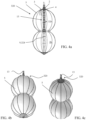
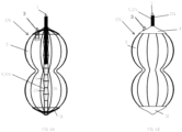
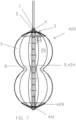
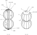
- occlusion device 320 optionally is configured to assume a figure-eight shape upon inflation.
- the figure-eight shape may be achieved by the thickness of an axial central portion of the struts 11, or by a limiting band that connect the struts 11 at that axial position of the narrower central portion of the figure eight, or by the thickness of the balloon 5 that results in less inflation in the narrower central portion of the figure eight.
- FIG. 6a shows a cross-sectional view of an expanded occlusion device 370.
- FIG. 6b shows a side elevational view of the occlusion device 370 illustrated in FIG. 6a .
- occlusion device 370 is identical to occlusion device 320, described hereinabove with reference to FIGS. 4a-c and 5a-c .
- the elongate actuating element 9 comprises an elongate actuating element 374 that is fixedly connected to the distal tip element 10.
- the elongate actuating element 374 is shaped so as to define a thread 376, and the locking mechanism 2 comprises a threaded opening defined by the proximal base element 4.
- the thread 376 of the elongate actuating element 374 is disposed within the threaded opening.
- the occlusion device 370 is configured such that rotation of the elongate actuating element 374 with respect to the proximal base element 4 causes the elongate actuating element 374 to longitudinally move with respect to the proximal base element 4, thereby setting the distance between the distal tip element 10 and the proximal base element 4 and maintaining the set distance.
- This arrangement allows both shortening of the distance and subsequent lengthening if necessary.
- the locking mechanism 2 is disposed at the proximal side 28A of the balloon 5, for example, connected to or integrated into the proximal base element 4.
- any excess proximal portion of the elongate actuating element 374 that extends through the proximal base element 4 to outside the occlusion device 370 is cut and removed from the body.
- the elongate actuating element 374 is not shaped so as to define the thread 376, and the locking mechanism 2 comprises a non-threaded opening defined by the proximal base element 4. Proximally pulling the elongate actuating element 374 sets the distance between the distal tip element 10 and the proximal base element 4. Once the desired distance has been set, the locking mechanism 2 is locked to fix the elongate actuating element 374 with respect to the proximal base element 4.
- the locking mechanism 2 is disposed at the proximal side 28A of the balloon 5, for example, connected to or integrated into the proximal base element 4.
- FIG. 6c shows a cross-sectional view of an expanded occlusion device 380.
- FIG. 6d shows a side elevational view of the occlusion device 380 illustrated in FIG. 6c .
- occlusion device 380 is identical to occlusion device 370, described hereinabove with reference to FIGS. 6a-b .
- the elongate actuating element 9 comprises an elongate actuating element 384 that is fixedly connected to the distal tip element 10.
- the locking mechanism 2 comprises a spool assembly 382, comprising a spool and, typically, a housing enclosing the spool. A proximal portion of the elongate actuating element 384 is wound around the spool.
- the occlusion device 380 is configured such that rotation of the spool causes the elongate actuating element 384 to longitudinally move with respect to the proximal base element 4, thereby setting the distance between the distal tip element 10 and the proximal base element 4 and maintaining the set distance. This arrangement allows both shortening of the distance and subsequent lengthening if necessary.
- the locking mechanism 2 is disposed at the proximal side 28A of the balloon 5, for example, connected to or integrated into the proximal base element 4.
- FIG. 6e shows a cross-sectional view of an expanded occlusion device 390.
- FIG. 6f shows a side elevational view of the occlusion device 390 illustrated in FIG. 6e .
- occlusion device 390 is similar to occlusion device 370, described hereinabove with reference to FIGS. 6a-b .
- the elongate actuating element 9 comprises an elongate actuating element 392 that is axially fixedly connected to a proximal base element 395.
- the elongate actuating element 392 is shaped so as to define a thread 396, and the locking mechanism 2, which is disposed at the distal side 28B of the balloon 5, comprises a threaded opening defined by a distal tip element 398.
- the thread 396 of the elongate actuating element 392 is disposed within the threaded opening.
- the occlusion device 390 is configured such that rotation of the elongate actuating element 392 with respect to the distal tip element 398 causes the elongate actuating element 392 to longitudinally move with respect to the distal tip element 398, thereby setting the distance between the distal tip element 398 and the proximal base element 395 and maintaining the set distance.
- This arrangement allows both shortening of the distance and subsequent lengthening if necessary.
- This configuration is appropriate for implantation locations in which the excess distal portion of the elongate actuating element 392 that protrudes from the distal side 28B of the occlusion device 390 upon shortening of the device does not interfere with the anatomy, such as in the LAA, as described hereinbelow with reference to FIGS. 12a-b .
- the proximal base element and a proximal portion of the elongate actuating element 392 together comprise a rotational ratchet mechanism 394, which is configured to allow rotation of the elongate actuating element 392 in only one rotational direction.
- Occlusion device 420 comprises a locking elongate element 8 that (a) passes through the locking mechanism 2 within the central lumen 6 and (b) is fixed to a distal tip element 410.
- the locking elongate element 8 is longitudinally slidable with respect to the proximal base element 4.
- the locking elongate element 8 is selected from the group consisting of: a tube, a wire, a shaft, a cable, a strand, and a fiber.
- elongate actuating element 9 comprises an elongate actuating element 424 that is disposed within the central lumen 6, is releasably connected to the distal tip element 410, and is longitudinally slidable with respect to the proximal base element 4.
- the elongate actuating element 424 is selected from the group consisting of a tube, a wire, a shaft, a cable, a strand, and a fiber.
- the locking mechanism 2 After longitudinal adjustment of the length of the occlusion device 20 by adjusting the distance between the proximal base element 4 and the distal tip element 410 by pulling and/or pushing the elongate actuating element 424, the locking mechanism 2 is activated, thereby securing the locking elongate element 8 within the locking mechanism 2 in the proximal base element 4 through which the locking wire 24 passes, in order to maintain fixed the distance between the proximal base element 4 and the distal tip element 410 set using the elongate actuating element 424.
- the locking mechanism 2 is disposed at the proximal side 28A of the balloon 5, for example, connected to or integrated into the proximal base element 4.
- the elongate actuating element 424 may be pulled and/or pushed directly by the user, in which case the axial movement of the elongate actuating element 424 pulls or pushes the distal tip element 410 in the direction of the proximal base element 4. Pulling or pushing the elongate actuating element 424 also causes corresponding motion of the locking elongate element 8 through the proximal base element 4, typically as a result of sufficient axial stiffness of the locking elongate element 8.
- a distal portion 426 of the elongate actuating element 424 may be shaped so as to define a thread 428, and the distal tip element 410 may be shaped so as to define a threaded opening to which the thread 428 of the distal portion 426 of the elongate actuating element 424 is releasably threadingly connected, such that the elongate actuating element 424 is releasably connected to the distal tip element 410.
- the elongate actuating element 424 is released from the distal tip element 410 by rotating the elongate actuating element 424, thereby unscrewing it from the distal tip element 410.
- the elongate actuating element 424 may be releasably connected to the distal tip element 410 using first and second positive connection elements, such as described hereinbelow with reference to FIG. 8 .
- the elongate actuating element 9 is not an element of the occlusion device 20, and indeed is disconnected from the occlusion device 20 during the implantation procedure and removed from the body.
- any excess proximal portion of the locking elongate element 8 that extends through the proximal base element 4 to outside the occlusion device 420 is cut and removed from the body.
- FIG. 8 shows a cross-sectional view of an expanded occlusion device 520.
- occlusion device 520 is identical to occlusion device 420, described hereinabove with reference to FIG. 7 .
- elongate actuating element 9 comprises an elongate actuating element 524, which, other than as described below, is similar to elongate actuating element 424, described hereinabove with reference to FIG. 7 .
- the elongate actuating element 524 is shaped so as to define a thread 526.
- the proximal base element 4 is shaped so as to define a threaded opening, and the thread 526 of the elongate actuating element 524 is disposed within the threaded opening.
- the elongate actuating element 524 is selected from the group consisting of: a tube, a wire (e.g., a plurality of wires woven together), a shaft, a cable, a strand, and a fiber.
- the elongate actuating element 524 may be rotated by the user, in which case the elongate actuating element 524 engages the threaded opening, such that rotation of the elongate actuating element 524 pulls a distal tip element 510 in the direction of the proximal base element 4 and causes shortening of the occlusion device 20, thereby setting the distance between the distal tip element 510 and the proximal base element 4 and maintaining the set distance.
- the locking mechanism 2 is disposed at the proximal side 28A of the balloon 5, for example, connected to or integrated into the proximal base element 4.
- a distal portion 530 of the elongate actuating element 524 may comprise a first positive connection element, and the distal tip element 510 may be shaped so as to define a second positive connection element.
- the first positive connection element is releasably connected to the second positive connection element, such that the elongate actuating element 524 is releasably connected to the distal tip element 510.
- the elongate actuating element 524 is released from the distal tip element 510 by decoupling the first positive connection element from the second positive connection element, such as by removing a retaining wire from within respective channels of the positive connection elements, as is known in the art.
- FIG. 9a shows a cross-sectional view of an expanded occlusion device 540.
- FIG. 9b shows a side elevational view of the occlusion device 540 illustrated in FIG. 9a .
- occlusion device 380 is identical to occlusion device 370, described hereinabove with reference to FIGS. 6a-b .
- the elongate actuating element 9 is connected to the distal tip element 10 by being looped through a distal pulley system 544 such that first and second portions 542A and 542B of the elongate actuating element 9 extend distally through the proximal base element. Proximal pulling of one or both of the portions 542A and 542B sets the distance between the distal tip element 10 and the proximal base element 4.
- the locking mechanism 2 comprises a locking mechanism 546, e.g., which uses compression and/or friction to hold the elongate actuating element 9, such as in a smaller channel of the locking mechanism 546.
- the locking mechanism 546 can be released after locking, in order to readjust the distance between the distal tip element 10 and the proximal base element 4, and then locked again. Locking the locking mechanism 546 maintains the distance set between the distal tip element 10 and the proximal base element 4. This arrangement allows both shortening of the distance and subsequent lengthening if necessary.
- the locking mechanism 546 is typically disposed at the proximal side 28A of the balloon 5, for example, connected to or integrated into the proximal base element 4.
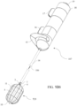
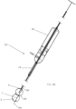
- FIG. 10a shows a cross-sectional view of the occlusion device 120 illustrated in FIG. 2a in a compressed form thereof within the implant catheter 14 of the delivery system 107, in accordance with an application of the present invention.
- FIGS. 10b and 10c show a perspective view and a cross-sectional view, respectively, of the occlusion device 120 illustrated in FIG. 2a , and of its main components, when released from the implant catheter 14 but still connected to the delivery system 107.
- FIGS. 10a-c show the occlusion device 120 by way of example; the delivery system 107 may also be used to deliver the other occlusion devices described herein, mutatis mutandis.
- the implant catheter 14 allows the introduction of the occlusion device 120 through the cardiovascular system to a defect in the cardiovascular apparatus, to deploy the occlusion device 120 to seal the defect and maintain the occlusion, or the introduction of the occlusion device 120 to another location in the patient's body.
- the delivery system 107 further comprises a multiple-knobs delivery system handle 18.
- the implant catheter 14 is connected to the occlusion device 120 by a proximal connection element 1.
- the implant catheter 14 contains the occlusion device 120 in its compressed form, i.e., its deflated and not expanded configuration.
- a greatest distance D between the proximal base element 4 and the distal tip element 10 is between 8 and 80 mm, such as between 10 and 60 mm.
- the "greatest distance” is the distance between respective points of the proximal base element 4 and the distal tip element 10, which points are farthest from each other.
- the delivery system 107 may also be used to deliver the other occlusion devices described herein, mutatis mutandis , in which case these other occlusion devices may optionally have the greatest distance D described immediately above.
- the delivery system 107 comprises all the components and passages to allow controllable occlusion device 120 exposure, inflation, deflation, longitudinal adjustment, retrievability, and release at the end of the implantation.
- the implant catheter 14 is typically steerable, as is known in the catheter art. In another configuration, the implant catheter 14 is flexible instead of steerable.
- Exposure of occlusion device 120 is controlled by an implant knob 16 in the delivery system handle 18.
- advancement of occlusion device 120 may be achieved by exposing and retrieving a connecting hypotube that is connected to the proximal base element 4.
- Retrieval may be achieved by pulling a securing wire that is placed within the hypotube, so as to hold the securing wire in position within a positive connection. Proximal withdrawal of the securing wire frees the positive connection, thereby releasing the occlusion device 120.
- the handle 18 comprises a disk actuating knob 17, which is arranged to move the elongate actuating element, to change the distance between the distal tip element 10 and the proximal base element 4, such as by rotating and/or pulling/pushing the elongate actuating element, depending on the specific configuration of the elongate actuating element, as described hereinabove.
- the delivery system 107 allows the course of the guidewire 106, used to guide the occlusion device 120 to the targeted defect, and of the elongate actuating element, used to adjust the length of the occlusion device 120, within the structure of the occlusion device and within the central lumen 6 of the occlusion device 120.
- the delivery system 107 includes mechanisms to inflate and deflate of the balloon 5 via an inflation port 19 in the handle 18.
- the delivery system 107 is configured to provide steering functionality in order to achieve good positioning of the occlusion device 120 in the targeted defect, for example controlled by a steering knob 15, including a steering limiter, within the delivery system handle 18.
- the steering functionality enables either an anterograde approach from the venous groin to the inferior vena cava, to the right atrium, to the left atrium, or a retrograde approach from the arterial groin to the left ventricle, and allows the occlusion device 120 implanted using any of the techniques known in the art.
- the frame 22, 122, or 222 comprising the proximal base element 4 and the distal tip element 10 (e.g., the proximal and distal disks 30 and 32) and the elongate actuating element 9, struts 11, or strut 12, respectively, has plastic or metallic deformable characteristics, and may comprise any suitable biocompatible material including stainless steel, titanium, nitinol, tantalum, gold, platinum iridium, tungsten, alloys of any of the above-mentioned metals, including platinum-iridium alloys, cobalt-chromium alloys, nickel-titanium alloys and nickel-titanium-platinum alloys.
- the frame 22, 122, or 222 may comprise a polymer, including a polyester or polycarbonate copolymers, or any metal or polymer or combination of polymer(s) and metal(s) able to provide soft plastic deformation.
- Suitable materials include biodegradable materials that are also biocompatible, intending a material that undergoes breakdown or decomposition into non-significant compounds as part of a normal biological process.
- Suitable biodegradable materials include polylactic acid, polyglycolic acid (PGA), collagen or other connective proteins or natural materials, polycaprolactone, hyaluronic acid, adhesive proteins, co-polymers of these materials as well as composites and combinations thereof and combinations of other biodegradable polymers.
- the frame 22, 122, or 222 and the balloon 5 of the occlusion device 20, 120, or 220, respectively, may be fabricated in different sizes, as necessary or appropriate for use in different sizes of cardiovascular defects or other suitable areas of the body.
- FIGS. 10a-c and to FIGS. 11a-b show side views of the occlusion device 120 illustrated in FIG. 2a at different respective stages of expansion within a congenital defect (e.g., patent foramen ovale (PFO)).
- FIGS. 11a-b show the occlusion device 120 by way of example; these techniques may also be used with the other occlusion devices described herein, mutatis mutandis.
- a method of occluding a cardiovascular defect of a patient not forming part of the claimed invention is provided.
- the method may be used to seal a gap between a medical device and adjacent body tissue of a patient;
- the medical device may be a prosthetic cardiac valve, and the method may treat paravalvular leak between the prosthetic cardiac valve and adjacent cardiac tissue of the patient.
- the guidewire 106 is advanced into a body of the patient using delivery system 107, such as shown in FIG. 10a .
- delivery system 107 compliant balloon 5 of the occlusion device 120 is positioned in a longitudinally extended form thereof (either partially or entirely compressed) in the cardiovascular defect, by advancing the occlusion device 120 over the guidewire 106.
- the balloon 5 is partially inflated before it is positioned in the longitudinally extended form thereof in the cardiovascular defect or the gap to be occluded.
- the balloon 5 is partially inflated, and, thereafter, is repositioned in the longitudinally extended form thereof in the cardiovascular defect or the gap to be occluded.
- the compliant balloon 5 is inflated by filling, via the inflation port 3 of the balloon 5, a fluid into the fluid-tight balloon chamber 26 defined by the balloon 5.
- FIG. 11a shows the occlusion device 20 after the balloon 5 has been inflated.
- the figure-eight shape shown in FIG. 11a may be achieved either because the defect constrains the balloon 5 to have the shape, and/or because the balloon 5 is configured to assume the shape even in the absence of the anatomy.
- the balloon 5 is expanded in a radial or a lateral direction by shortening the distance between the distal tip element 10 and the proximal base element 4 to a desired distance and locking the distance.
- the radial or lateral expansion provides a good seal between the balloon and the adjacent anatomy.
- FIG. 11b shows the occlusion device 20 after the balloon 5 has been radially or laterally expanded.
- the occlusion device 120 is released from the delivery system 107.
- the proximal base element 4 and the distal tip element 10 are shaped so as to define the above-mentioned respective guidewire openings 105a and 105b substantially coaxial to the balloon lumen 6 for slidingly receiving therein the guidewire 106, and advancing the occlusion device 120 over the guidewire 106 comprises sliding the guidewire 106 through the guidewire openings 105a and 105b described hereinabove.
- the balloon 5 has the above-mentioned balloon lumen 6 forming the above-mentioned longitudinal passage 27 from the proximal side 28A to the distal side 28B of the balloon 5.
- the distance between the distal tip element 10 and the proximal base element 4 is shortened to the desired distance by pulling the elongate actuating element 9 disposed longitudinally slidable in the balloon lumen 6, connected to the distal tip element 10, and longitudinally moveable with respect to the proximal base element 4.
- the distance is locked using locking mechanism 2 for maintaining, between the distal tip element 10 and the proximal base element 4, the distance set using the elongate actuating element 9.
- the occlusion device 120 is released from the delivery system 107 by releasing the above-mentioned proximal connection element 1 of the occlusion device 120 from the correspondingly configured distal connection element of the delivery system 107.
- the balloon 5 is partially exposed, in its compressed form, from the implant catheter 14 of the delivery system 107 into the area to be treated (e.g., exposed for half of the length of the balloon 5), and only the exposed portion of the balloon 5 is inflated.
- the balloon 5 is then repositioned for better occlusion targeting, and the balloon 5 is subsequently fully exposed from the delivery system 107, and the remaining portion of the balloon 5 is inflated. Subsequently, the longitudinal distance is shortened.
- a portion of the balloon 5 is exposed, in its compressed form, from the implant catheter 14 of the delivery system 107 into the area to be treated (e.g., exposed for half of the length of the balloon 5), and only the exposed portion of the balloon 5 is inflated.
- the exposed portion of the balloon 5 is expanded by shortening the distance between the distal tip element 10 and the proximal base element 4 by moving the distal tip element 10 toward the proximal base element 4.
- the remainder of the balloon 5 is exposed from the implant catheter, inflated, and expanded by further shortening the distance between the distal tip element 10 and the proximal base element 4.
- positioning and inflating the compliant balloon comprise positioning the balloon 5 in a ventricle of the patient; thereafter, partially inflating the balloon 5; thereafter, disposing the balloon 5 approximately at a longitudinal center of the paravalvular leak; and thereafter, further inflating the balloon 5.
- the balloon 5 is expanded after further inflating the balloon 5.
- the balloon 5 is disposed approximately at the longitudinal center of the paravalvular leak by proximally withdrawing the balloon 5 until the balloon 5 is disposed approximately at the longitudinal center of the paravalvular leak.
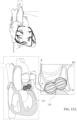
- FIGS. 12a-b show side views of the occlusion device 120 illustrated in FIG. 2a when expanded within a cavity or discontinuity of the body tissue.
- the cavity or discontinuity may be a cardiovascular defect, such as a left atrial appendage (LAA).
- FIGS. 12a-b show the occlusion device 120 by way of example; these techniques may also be used with the other occlusion devices described herein, mutatis mutandis.
- the deployment method described hereinabove with reference to FIGS. 10a-c and 11a-b may be used to achieve the implantations shown in FIGS. 12a-b , mutatis mutandis.
- the balloon 5 is configured to have a figure-eight shape (as shown in FIG. 12a ), a pear shape (as shown in FIG. 12b , or a multilobed shape.
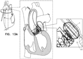
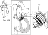
- FIGS. 13a-b show side views of the occlusion device 120 illustrated in FIG. 2a when expanded within a gap between a medical device and the adjacent body tissue, in accordance with an application of the present invention.
- the medical device may comprise a stent, such as a stent of a prosthetic valve.
- FIGS. 13a-b shows occlusion device 120 by way of example; these techniques may also be used with the other occlusion devices described herein, mutatis mutandis.
- the deployment method described hereinabove with reference to FIGS. 10a-c and 11a-b may be used to achieve the implantation shown in FIGS. 13a-b , mutatis mutandis.
- the frame 122 of the occlusion device 120 comprises a backbone strut 111 that connects the proximal base element 4 and the distal tip element 10, and is thicker than the other struts 11, if provided.
- the backbone strut 111 is configured to reduce relative inflation on its lateral side of the balloon 5 compared to inflation of the balloon elsewhere, thereby providing a balloon shape that is appropriate for the anatomy of the gap to be filled.
- the wall of the balloon 5 on one lateral side may be thicker longitudinally on one lateral side, to create the backbone that causes the balloon to inflate less on that side.
- FIG. 14a shows a cross-sectional view of an expanded occlusion device 720.
- FIG. 14b and 14c show side elevational views of the occlusion device 720 illustrated in FIG. 14a .
- occlusion device 720 may implement any of the features of the other occlusion devices described hereinabove (including, but not limited to occlusion devices 20, 120, 220, 320, 370, 380, 390, 420, 520, and 540) or hereinbelow (including, but not limited to occlusion device 620).
- the occlusion device 720 comprises a frame 722 that comprises a plurality of struts 711, which may have any suitable form, passing inside (not shown) or outside (as shown) and tapering the balloon 5 component.
- struts 711 may have any suitable form, passing inside (not shown) or outside (as shown) and tapering the balloon 5 component.
- Such an application may allow a cage-like structural confinement of the balloon 5 within its assembly, to avoid unnecessary interference of the occlusion device 720 with the body tissue or with implanted prostheses and to provide anchoring support of the occlusion device 720 within the defect, e.g., the cardiovascular defect.
- the frame 722 may comprise 2, 4, 6, 8, 10, 12 or any other suitable even or odd number of struts 711.
- the struts 711 may be disposed inside or outside the balloon 5.
- the struts 711 are not fixed to any surfaces of the balloon 5.
- the struts 711 are (a) fixed to a surface (inner or outer) of the balloon 5, (b) embedded in the wall of the balloon 5 during manufacture (such as by being cast within the wall).
- the balloon 5 may be molded over the struts 711, which remain internally fixed to the balloon 5.
- the struts 711 are not arranged parallel with a central longitudinal axis 713 of the occlusion device 720.
- the struts 711 may be arranged in a generally helical configuration around the balloon 5, such as shown.
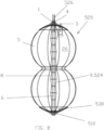
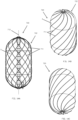
- FIG. 15a shows a cross-sectional view of an expanded occlusion device 820.
- FIG. 15b and 15c show side elevational views of the occlusion device 820 illustrated in FIG. 15a .
- occlusion device 820 is identical to occlusion device 720, described hereinabove with reference to FIGS. 14a-c and may implement any of the features thereof or of the other occlusion devices described hereinabove (including, but not limited to occlusion devices 20, 120, 220, 320, 370, 380, 390, 420, 520, and 540) or hereinbelow (including, but not limited to occlusion device 620).
- the occlusion device 820 comprises a frame 822 that comprises a plurality of struts 811, which may have any of the features of the frame 722 and/or the struts 711 described hereinabove with reference to FIGS. 14a-c .
- the struts 811 are not arranged parallel with a central longitudinal axis 813 of the occlusion device 820.
- the struts 811 may be arranged in a zig-zag configuration around the balloon 5, optionally including partially helical portions, such as shown.
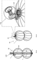
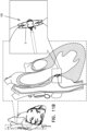
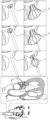
- FIG. 16 shows a method of deploying the occlusion device 120.
- FIG. 16 shows the occlusion device 120 by way of example; these techniques may also be used with the other occlusion devices described herein, mutatis mutandis.
- the first frame of FIG. 16 shows the delivery system 107 approaching the left atrial appendage defect.
- the second frame shows half of the occlusion device 120 exposed and pre-inflated.
- the third frame shows half of the occlusion device 120 adjusted.
- the fourth frame shows the other half of the occlusion device 120 exposed and pre-inflated.
- the fifth frame shows full inflation of the entire occlusion device 120, and further adjustment that shortens the distance between the proximal base element 4 and the distal tip element 10.
- the sixth (last) frame shows release of the occlusion device 120 at the target location.
- FIG. 17a shows a cross-sectional view of an expanded occlusion device 620 according to an application of the present invention.
- FIG. 17b shows a side elevational view of the occlusion device 620 illustrated in FIG. 17a , in accordance with an application of the present invention.
- the occlusion device 620 may implement any of the features of the other occlusion devices described herein, mutatis mutandis, including, but not limited to, the struts of the frames described herein and the materials of the components of the occlusion devices.
- Like reference numerals refer to like parts.
- the occlusion device 620 comprises:
- the balloon 5 has the balloon lumen 6 forming the longitudinal passage 27 from the proximal side 28A to the distal side 28B of the balloon 5.
- the elongate element 608 is disposed in the balloon lumen 6.
- the proximal base element 604 and the distal tip element 10 are shaped so as to define respective guidewire openings 605a and 605b substantially coaxial to the balloon lumen 6 for slidingly receiving therein the guidewire 106.
- proximal base element 604 and the distal tip element 10 comprise a proximal disk 630 and the distal disk 32, respectively.
- the occlusion device 620 further comprises at least one connecting strut fixed to the distal tip element and to the proximal base element, such as the single connecting strut 21 described hereinabove with reference to FIGS. 1a-c , the single connecting strut 12 described hereinabove with reference to FIGS. 3a-c , or the plurality of struts 11 described hereinabove with reference to FIGS. 2a-c .
- the strut or struts may be disposed inside and/or outside the balloon 5, and be arranged as described hereinabove.
- a method of occluding a cardiovascular defect or a gap between a medical device and adjacent body tissue of a patient comprises:
- two or more occlusion devices are implanted to occlude a defect, either in series and/or alongside one another.
- frames of the two or more occlusion devices are configured to connect the two or more occlusion devices together, typically in situ during an implantation procedure.
- a portion of the surface of one of the balloons is bare of any of the frame, and the frame of another balloon is brought into contact with the bare portion of the other balloon, such as in order to avoid para-balloon leakage.
- the occlusion devices described herein are packaged in sterile packaging.
- the balloon 5 may optionally have an average wall thickness of between 100 and 5000 microns, such as between 200 and 1000 microns. Alternatively, the balloon 5 does not have this average wall thickness.
- the balloon 5 may optionally have, at a thinnest portion of a wall of the balloon 5, a thinnest wall thickness of between 20 and 500 microns, such as between 40 and 100 microns. Alternatively, the balloon 5 does not have this thinnest wall thickness.
- the occlusion device may comprise a proximal radiopaque marker 23 that is fixed to the proximal base element and comprises a material that is more radiopaque than the proximal base element.
- the occlusion device may comprise a distal radiopaque marker 25 that is fixed to the distal tip element and comprises a material that is more radiopaque than the distal tip element.
- proximal and distal radiopaque markers 23 and 25 are shown by way of example in FIGS. 1b and 1c ; these markers may also be provided in the other occlusion devices described herein.
- the occlusion devices described herein do not comprise proximal radiopaque marker 23 or distal radiopaque marker 25.
- each of the proximal radiopaque marker 23 and/or the distal radiopaque marker 25 may be shaped as a ring, such as shown in FIGS. 1b and 1c ; alternatively, the markers may have other shapes and/or different shapes or sizes from each other.
- the material of the proximal radiopaque marker 23 and/or the distal radiopaque marker 25 may comprise Au, PtIr, or Ta.
- proximal radiopaque marker 23 and/or the distal radiopaque marker 25 may be fixed to the proximal base element and the distal tip element, respectively, by gluing, soldering, crimping, or welding.
- a greatest distance between the proximal base element 4 and the distal tip element 10 is between 8 and 80 mm, such as between 10 and 60 mm.
- the "greatest distance” is the distance between respective points of the proximal base element 4 and the distal tip element 10, which points are farthest from each other.
- the occlusion device is in the above-mentioned compressed, uninflated form when the proximal connection element 1 is attached to the delivery system 107 and the occlusion device is not disposed in the implant catheter 14.
Landscapes
- Health & Medical Sciences (AREA)
- Life Sciences & Earth Sciences (AREA)
- Surgery (AREA)
- Engineering & Computer Science (AREA)
- Biomedical Technology (AREA)
- Veterinary Medicine (AREA)
- Public Health (AREA)
- General Health & Medical Sciences (AREA)
- Heart & Thoracic Surgery (AREA)
- Animal Behavior & Ethology (AREA)
- Molecular Biology (AREA)
- Medical Informatics (AREA)
- Nuclear Medicine, Radiotherapy & Molecular Imaging (AREA)
- Cardiology (AREA)
- Vascular Medicine (AREA)
- Reproductive Health (AREA)
- Oral & Maxillofacial Surgery (AREA)
- Transplantation (AREA)
- Prostheses (AREA)
- Surgical Instruments (AREA)
- Media Introduction/Drainage Providing Device (AREA)
Description
- The present patent application is a continuation-in-part of International Application
PCT/EP2018/075716, filed September 23, 2018 European Appl. No. 17192792.4, filed September 23, 2017 - The present invention generally relates to an occlusion device for occluding a cardiovascular defect or a gap between a medical device and adjacent body tissue and a system comprising the occlusion device and a delivery system cooperating therewith.
- There are several types of unnecessary or even pathologic passageways within the body. If located in blood vessels or in the heart, such passageways can cause a highly undesirable alteration of blood flow or the bypass of blood flow around an organ.
-
WO 95/32018 -
US 4,836,204 describes a device for effecting closure of a perforation in the septum of the heart. The device comprises a double-balloon septal defect occlusion catheter which is to be inserted such that the two initially deflated balloons are positioned on opposing sides of the septum. Upon inflating, the balloons snugly engage the respective septum wall sections and thereby prevent leakage through the perforation. - Paravalvular leak is a common complication that occurs in up to 30% of patients undergoing implantation of either surgical or transcatheter prostheses. The option to treat these defects percutaneously may offers safer solution for high-risk patients, without exposing them to risk related to open heart reoperation. However, the currently used devices are suboptimal since they have not been specifically developed with this intended use. Today, paravalvular leak closure is generally accomplished with devices originally designed for occlusion of congenital heart defects. They are usually implanted in a low-flow environment such as patent foramen ovale or atrial septum defect, and in simple geometries. In contrast, paravalvular leaks develop in high pressure and flow environment, and they are characterized by complex geometry. The defect is often crescent or oval shaped, which may include a tubular section with several deformities, and the structure is marginally compliant at best.
- The left atrial appendage (LAA) is a cavity that presents in the left atrium of the heart. In patients with atrial fibrillation the passage and steadiness of blood within this cavity can cause thrombus formation, which increase the risk of stroke. Percutaneous LAA occlusion is a therapy for the prevention of stroke in patients with atrial fibrillation. LAA occlusion is used as an alternative to, or in combination with, oral anticoagulant therapy. LAA occlusion has favorable clinical outcomes, but commercially-available devices are typically self-expandable, and not designed to adapt to the anatomy, thus sometimes resulting in complications or suboptimal outcomes. In these environments, some of the currently available occlusion devices are limited by the poor adaptability of the device to the defect (lack of conformability) and by a lack of intra-device sealing (due to the high flow environment).
- Nevertheless, there are some concepts and implementations of occlusion devices that were specifically designed for paravalvular leak occlusion or LAA occlusion.
-
US 2014/0277426 A1 describes various devices for occluding a gap between a medical device and adjacent body tissue. The devices generally comprise a conformable body with a hollow interior and provided with a fluid port intended to supply a pressurizing fluid to inflate the conformable body. Various shapes and constitutions of the conformable body, delivery means and fixing means are described. -
US 7,628,805 generally describes a multitude of concepts for locating and for repairing paravalvular leaks. The concepts include sealing stents and also multicomponent and radiation-cured adhesive compounds. -
US 2012/078295 describes an occluder device for closing a passage in a circulatory system. The device comprises an expandable fixation unit for fixing the occluder on the passage, which is achieved by switching between a compact form and an expanded form. -
EP 1974685 discloses a medical retainer capable of independently controlling supplying air and water to a hollow organ like a stomach and a lumen of a small intestine. -
US 3834394 discloses a method of effecting the occlusion of a blood vessel by forming an access opening in the body of the patient communicating with the desired blood vessel, introducing an occlusion member in the vessel, moving the member to the desired point of occlusion, and thereat expanding the member to a size greater than the diameter of the vessel whereby the member is substantially immovably retained therein. -
US 2014/100596 discloses that a medical device for reducing the volume of a left atrial appendage (LAA) may include an elongate shaft having a distal portion, and a volume-reducing means expandable from a collapsed to an expanded state, the volume-reducing means being releasably attached to the distal portion. - In spite of the above, there is still a need for an improved occlusion device which avoids the shortcomings of presently known devices.
- In some applications of the present invention, an occlusion device is provided for occluding a cardiovascular defect or a gap between a medical device and adjacent body tissue. The invention is set out in the appended set of claims. The occlusion device is for use with a guidewire and a delivery system. The occlusion device comprises:
- a compliant balloon defining a fluid-tight balloon chamber, having a balloon lumen forming a longitudinal passage from a proximal side to a distal side of the balloon, and comprising an inflation port for filling and unfilling a fluid into and from the balloon chamber;
- a distal tip element disposed at the distal side of the balloon, and a proximal base element disposed at the proximal side of the balloon;
- an elongate actuating element having a fixed length, and fixed to the distal tip element and the proximal base element, the elongate element comprising a wire or a cable; and
- a proximal connection element that is disposed at the proximal side of the balloon and is configured to releasably connect the occlusion device to a correspondingly configured distal connection element of the delivery system;
- the elongate element is fixed to the distal tip element and the proximal base element so as to set a fixed distance between the distal tip element and the proximal base element,
- the balloon has a balloon lumen forming a longitudinal passage from the proximal side to the distal side of the balloon, and
- the elongate element is disposed in the balloon lumen.
- According to another aspect, there is provided an occlusion system comprising an occlusion device as described above and a delivery system (comprising a catheter device) cooperating therewith. The catheter device comprises an implant catheter tube connected to an operating handle. The implant catheter tube comprises a longitudinal passageway for a guidewire, a distal connection element for releasably connecting the catheter device to a correspondingly configured proximal connection element of the occlusion device, and a fluid transfer system releasably connectable to a corresponding inflation port of the occlusion device. The distal connection element and the proximal connection element are generally configured as cooperating members disposed, respectively, at the distal end of the catheter device and at the proximal end of the occlusion device. Examples for such cooperating members comprise cooperating threads, bayonets, or snap connections.
- Clinical indications include but are not limited to paravalvular leak (PVL), patent foramen ovale (PFO), atrial septum defect (ASD), ventricular septum defect (VSD), intravalvular leak (IVL), intraleaflet leak, leaflet perforation, type I endovascular leaks after vascular graft implant, left or right heart apex closure after transapical therapeutic access, and left atrial appendage occlusion.
- The occlusion device is designed to be delivered into the region to be treated in its longitudinally extended form, either entirely or partially compressed. After delivery, the occlusion device is adapted to the landing zone anatomy by inflating the balloon and subsequently shortening of the longitudinal dimension of the frame formed between the proximal base element and the distal tip element. Under the influence of internal pressure, the balloon will assume a certain volume which, for a given longitudinal frame dimension, results in a certain lateral or radial dimension, which provides a good seal between the balloon and the adjacent anatomy or implanted medical device. Changing the longitudinal frame dimension by selecting a different distance between the distal tip element and the proximal base element will lead to a corresponding change in the radial or lateral extension of the balloon. In other words, shortening the distance between the distal tip element and the proximal base element leads to a corresponding increase in radial or lateral extension under otherwise constant conditions, which improves the seal with the adjacent tissue and/or medical device and seals unwanted blood passage. The lateral extension of the balloon is not necessarily symmetric, either because the balloon is not necessarily symmetric and/or because the anatomy against which the balloon is laterally expanded may cause asymmetric balloon expansion. The radial or lateral expansion together include within their scope one or more directions generally perpendicular to the longitudinal axis of the balloon. (Optionally, the balloon is partially inflated (e.g., to atmospheric pressure) and the longitudinal dimension of the frame is shortened; the balloon may subsequently be further inflated before release, such as if necessary to make the good seal between the balloon and the adjacent anatomy or implanted medical device.)
- In the context of the present disclosure, the terms "distal" and "proximal" are used accordingly to their standard meaning in the field of percutaneous cardiovascular devices. The term "proximal" refers to those components of the device assembly which, when following a delivery catheter during percutaneous delivery, are closer to the end of the catheter that is configured for manipulation by the user (e.g., catheter handle manipulated by a physician). The term "distal" is used to refer to those components of the device assembly that are more distant from the end of the catheter that is configured for manipulation by the user and/or that are inserted further into the body of a patient. Accordingly, in an occlusion device for use in a gap between a medical device and the adjacent body tissue, like a paravalvular mitral leak, the proximal end may face towards the left atrium and the distal end may face towards the left ventricle, when the occlusion device is deployed in the defect using a transseptal approach.
- The term "compliant" used in relation with balloons or with structural components shall be understood as implying a deformability that substantially follows an applied force. Accordingly, a "compliant balloon" shall be understood as a balloon which progressively expands under the effect of increasing radial pressure as long as a certain burst pressure is not exceeded.
- The term "strut" shall be understood as an elongate structural element which can be formed e.g. as a thin wire, rod, thick-walled tube, all of which do not necessarily have a circular cross section.
- The compliant balloon of the occlusion device is not necessarily pre-shaped since the balloon, because it is compliant, takes the shape of the defect once inflated within the defect. However, for some applications, the wall of the balloon has a different thickness in a specific area (e.g., centrally, such that the balloon assumes a figure-eight shape upon inflation, or longitudinally on one side, to create a backbone that causes the balloon to inflate less on that side). In addition, pre-shaped balloons can be used to establish a predetermined, non-uniform local resilience against an applied radial pressure.
- For some applications, the balloon comprises silicone, polyurethane, polytetrafluoroethylene (PTFE), polymethylmethacrylate, polyether ether ketone (PEEK), polyvinyl chloride, polyethylene terephthalate, nylon, polyamide, polyamide, polyether block amide (PEBA), or another biocompatible material. For some applications, the balloon comprises a compliant, biodegradable material selected from polycaprolactone (PCL), polyglycolic acid (PGA), polylactic acid (PLA), and polydioxanone (PDO or PDS). Optionally, the balloon is treated externally with a hydrophilic coating, hydrophobic coating, an anti-inflammatory coating, anticoagulation coating, or other coating to promote endothelial growth, such as chemically or by modifying the porosity of the external surface of the balloon.
- For some applications, the proximal base element and the distal tip element are connected by one or more struts. Depending on the specific application, various configurations of the struts may be contemplated. According to one application, the struts comprise a single connecting strut disposed within the balloon lumen or outside the balloon. For other applications, the struts comprise a plurality of struts, e.g., disposed in a cage-like manner outside the balloon. Applying internal pressure to the balloon will lead to inflation thereof against a resilient force of the compliant balloon material and also against the structural limitation provided by the plurality of external connecting struts. In particular, such a configuration may offer the advantage of an improved stability of the compliant balloon against unwanted local deformation. This will generally result in an improved adaptation of the occlusion device to the geometry of the defect to be occluded.
- The locking mechanism for maintaining a predetermined distance between the distal tip element and the proximal base element may also be configured in various manners. For example, the locking mechanism may comprise a rotatable elongate actuating element (e.g., a wire) with a threaded portion formed to cooperate with a corresponding section formed in the proximal base element. For some applications, the locking mechanism is configured as a ratchet mechanism such that the distance between the distal tip element and the proximal base element is selectable from a range of distances. This allows for precise and reliable definition of the radial extension of the occlusion device and accordingly to improved reliability of the occlusion device.
- The elongate actuating element is disposed longitudinally slidable in the balloon lumen, connected to the distal tip element and longitudinally slidable with respect to the proximal base element so as to set a distance between the distal tip element and the proximal base element. For this purpose, the elongate actuating element is typically formed as an elongate, flexible member with a smooth surface. For some applications, the elongate actuating element is configured as actuating wire. The use of actuating wires is well established in the field of cardiovascular interventions. In the present context, the use of a wire together with appropriate proximal counterpieces allows for simple, precise and reproducible selection of the distance between the distal tip element and the proximal base element.
- Means for filling and unfilling balloons and other inflatable devices are also well known in the field of cardiovascular interventions. For some applications, the balloon has an inflation port configured as a self-closing valve when it is not connected to a corresponding fluid transfer system of the delivery system. In particular, this allows filling the balloon through a longitudinal fluid line which can subsequently be disconnected and retracted and which only needs to be reinserted and reconnected if an additional filling or an unfilling of the balloon is needed.
- The aforementioned elements as well as those claimed and described in the following and to be used according to the invention, shall generally be understood with their meaning as established in the field of medicine.
- The above mentioned and other features and objects of this invention and the manner of achieving them will become more apparent and this invention itself will be better understood by reference to the following description of various embodiments of this invention taken in conjunction with the accompanying drawings, in which:
The present invention will be more fully understood from the following detailed description of embodiments thereof, taken together with the drawings, in which: -
-
FIG. 1a shows a cross-sectional view of an expanded occlusion device; -
FIGS. 1b and 1c show side elevational views of the occlusion device illustrated inFIG. 1a ; -
FIG. 2a shows a cross-sectional view of an expanded occlusion device; -
FIGS. 2b and 2c show side elevational views of the occlusion device illustrated inFIG. 2a ; -
FIG. 3a shows a cross-sectional view of an expanded occlusion device; -
FIGS. 3b and 3c show side elevational views of the occlusion device illustrated inFIG. 3a ; -
FIG. 4a shows a cross-sectional view of an expanded occlusion device; -
FIGS. 4b and 4c show side elevational views of the occlusion device illustrated inFIG. 4a ; -
FIG. 5a shows a cross-sectional view of the occlusion device illustrated inFIG. 4a after the ratchet component actuation and longitudinal shortening; -
FIGS. 5b and 5c show side elevational views of the occlusion device illustrated inFIG. 5a ; -
FIG. 6a shows a cross-sectional view of an expanded occlusion device; -
FIG. 6b shows a side elevational view of the occlusion device illustrated inFIG. 6a ; -
FIG. 6c shows a cross-sectional view of an expanded occlusion device; -
FIG. 6d shows a side elevational view of the occlusion device illustrated inFIG. 6c ; -
FIG. 6e shows a cross-sectional view of an expanded occlusion device; -
FIG. 6f shows a side elevational view of the occlusion device illustrated inFIG. 6e ; -
FIG. 7 shows a cross-sectional view of an expanded occlusion device; -
FIG. 8 shows a cross-sectional view of an expanded occlusion device; -
FIG. 9a shows a cross-sectional view of an expanded occlusion device; -
FIG. 9b shows a side elevational view of the occlusion device illustrated inFIG. 9a ; -
FIG. 10a shows a cross-sectional view of the occlusion device illustrated inFIG. 2a in a compressed form thereof within an implant catheter of a delivery system; -
FIGS. 10b and10c show a side view and a cross-sectional view, respectively, of the occlusion device illustrated inFIG. 2a when released from the implant catheter but still connected to the implant delivery system; -
FIGS. 11a and11b show side views of the occlusion device illustrated inFIG. 2a at different respective stages of expansion within a congenital defect; -
FIGS. 12a and12b show side views of the occlusion device illustrated inFIG. 2a when expanded within a cardiovascular defect intended as cavity or discontinuity of the body tissue; and -
FIGS. 13a and13b show side views of the occlusion device illustrated inFIG. 2a when expanded within a gap between a medical device and the adjacent body tissue; -
FIG. 14a shows a cross-sectional view of an expanded occlusion device; -
FIGS. 14b and 14c show side elevational views of the occlusion device illustrated inFIG. 14a ; -
FIG. 15a shows a cross-sectional view of an expanded occlusion device; -
FIGS. 15b and 15c show side elevational views of the occlusion device illustrated inFIG. 15a ; -
FIG. 16 shows a method of deploying the occlusion device illustrated inFIG. 2a ; -
FIG. 17a shows a cross-sectional view of an expanded occlusion device according to an application of the invention, in accordance with an application of the present invention; and -
FIG. 17b shows a side elevational view of the occlusion device illustrated inFIG. 17a , in accordance with an application of the present invention. - It will be understood that the figures are not necessarily drawn to scale. In some instances, relative dimensions may be substantially distorted for ease of visualization.
-
FIG. 1a shows a cross-sectional view of an expandedocclusion device 20.FIGS. 1b and 1c show side elevational views of theocclusion device 20 illustrated inFIG. 1a . Occlusion device is for use with aguidewire 106 and a delivery system 107 (shown inFIGS. 10a-c ). As shown, theocclusion device 20 comprises acompliant balloon 5 having acentral balloon lumen 6 forming alongitudinal passage 27 through an interior of theballoon 5 from aproximal side 28A to adistal side 28B of theballoon 5. Theballoon 5 defines a fluid-tight balloon chamber 26. Theballoon 5 is typically compliant, as defined above. Optionally, theballoon lumen 6 is foldable, such that theballoon lumen 6 closes on itself after the guidewire 106 (shown inFIGS. 10a-c ) is removed, so not to leave an open passage within theocclusion device 20. For example, the foldability of theballoon lumen 6 may be provided by providing proximal and distal valves on the entrances of theballoon lumen 6, or by configuring theballoon lumen 6 to collapse and fold longitudinally. - The
occlusion device 20 further comprises aframe 22 comprising aproximal base element 4 and adistal tip element 10, disposed at the proximal anddistal sides balloon 5, respectively, and connected by anelongate actuating element 9 passing and longitudinally slidable within thecentral lumen 6 of theballoon 5. Theelongate actuating element 9 is longitudinally moveable with respect to theproximal base element 4 so as to set a distance between thedistal tip element 10 and theproximal base element 4. Typically, theelongate actuating element 9 is selected from the group consisting of: a tube, a wire, a shaft, a cable, a strand, and a fiber. Reduction of the distance may cause thedistal tip element 10 to move toward theproximal base element 4, theproximal base element 4 to move toward thedistal tip element 10, or both movements. - For some applications, the
proximal base element 4 and thedistal tip element 10 comprise a proximal disk 30 and a distal disk 32, respectively. Theframe 22 provides structural support to theballoon 5. Theframe 22 may be formed from a cut structure so that each component of theframe 22 is integrally connected with each other. Theelongate actuating element 9 may have a linear or nonlinear section and may have plastic or metallic deformable characteristics. - The
occlusion device 20 further comprises alocking mechanism 2 for maintaining, between thedistal tip element 10 and theproximal base element 4, the distance set using theelongate actuating element 9. For example, thelocking mechanism 2 may comprise a crimping element, a threaded element, a locking element, an inflatable balloon, a locking wire, or a ratchet element. For some applications, thelocking mechanism 2 is disposed at theproximal side 28A of theballoon 5, for example, connected to or integrated into theproximal base element 4. - The
occlusion device 20 is shaped so as to form a closed three-dimensional shape. Theocclusion device 20 comprises aproximal connection element 1 that is configured to attach theocclusion device 20 to and release theocclusion device 20 fromdelivery system 107, e.g., from animplant catheter 14 ofdelivery system 107. It is noted that thelongitudinal passage 27 is still defined through the interior of theballoon 5 after release of theocclusion device 20 from theimplant catheter 14. Typically, when theocclusion device 20 is connected to theimplant catheter 14, no portion of theimplant catheter 14 is disposed within the interior of theballoon 5. - Typically, the
proximal base element 4 and the distal tip element 10 (e.g., the proximal and distal disks 30 and 32) are shaped so as to definerespective guidewire openings balloon lumen 6 for slidingly receiving therein guidewire 106 (shown inFIGS. 10a-c ) for delivering theocclusion device 20. - For some applications, the
proximal base element 4 and the distal tip element 10 (e.g., the proximal and distal disks 30 and 32) are deformable, such as to allow the elements to automatically adjust their shapes upon inflation of theballoon 5. Alternatively, theproximal base element 4 and the distal tip element 10 (e.g., the proximal and distal disks 30 and 32) are not deformable. - For some applications, the
proximal base element 4 and the distal tip element 10 (e.g., the proximal and distal disks 30 and 32) comprise a plastic or a metal, e.g., Nitinol. - Although the proximal and distal disks 30 and 32 are shown as circular in the figures, the disks may have other shapes, such as the shape of a flower, a cross, a star, an ellipse, or any other shape as necessary or appropriate for proper cardiovascular defects occlusion and device stabilization. The proximal and distal disks 30 and 32 are typically radially symmetric, but may also be asymmetric.
- The
occlusion device 20 further comprises aninflation port 3 entering into theballoon 5 along a central axis of theballoon 5 or elsewhere, such as in close vicinity of the central axis. Theinflation port 3 is releasably connected to an inflation tube channel of theimplant catheter 14 and allows inflation and deflation of theballoon 5 while connected before release of theocclusion device 20 from theimplant catheter 14. Within thecentral lumen 6 of theballoon 5, theballoon 5 may define aguidewire lumen 7 allowing guidewire 106 (shown inFIGS. 10a-c ) to freely move axially through theocclusion device 20. Typically, in configurations in which the proximal opening of theguidewire lumen 7 is centered around the central axis of theballoon 5, theinflation port 3 is off-center, and vice versa. - According to an application of the present invention, the
compliant balloon 5 may be inflated by filling theballoon chamber 26 with any fluid, including but not limited to saline solution (optionally comprising a contrast medium), blood (e.g., autologous blood), foam, and a glue (e.g., a gel, a liquid polymer that can change its proprieties to become rigid, or a hydrogel that remains a gel or self-cures at body temperature). For applications in which the fluid includes autologous blood, the autologous blood may be drawn from the patient during the deployment of theocclusion device 20, e.g., at a location proximal to theballoon 5 within the patient's body, or drawn from the patient outside the patient's body and filled into theballoon chamber 26 via the deployment system. For applications in which the fluid includes blood, an anti-coagulation agent may be mixed with the blood in order to delay coagulation for a while in case theballoon 5 must be retrieved; eventually the blood coagulates. - The above-mentioned fluid provides the long-term shape setting, sealing and occluding properties of the expanded
occlusion device 20. Theballoon 5 provides the acute, i.e., immediate shape setting, sealing, and occluding properties of the expandedocclusion device 20. Therefore, for applications in whichocclusion device 20 is radiopaque and is implanted in a beating heart under echocardiographic, fluoroscopic, and/or x-ray guidance, upon inflation of theballoon 5, the surgeon can immediately observe whether the defect has been occluded (by observing cessation of blood flow through the defect). The immediate closure of the defect upon inflation of theballoon 5 contrasts with known closure devices comprising a braided wire mesh, which generally do not provide immediate closure of the defect, but instead only provide good closure upon sufficient blood clotting in the mesh after several days or weeks. Thus the effectiveness of these known closure devices can generally only be evaluated at least several days after implantation. - The
implant catheter 14 and theinflation port 3 may contain specific channels, valves and membranes designed to be compatible with the fluid used, including filter membranes that can be permeable to blood in the case blood is used as filling fluid of theballoon chamber 26. - Moreover, the
frame 22 allows longitudinal adjustment of theballoon 5 to enhance the stability of theocclusion device 20 and to enhance occlusion of the defect. - In some applications, the
frame 22 may be designed to have a limited conformability (for example, because of the thickness of theframe 22 or a material property of the frame 22), such as in order to create a tapered shape to provide asymmetrical confinement to theballoon 5, for example, tapered at the distal end, such that theballoon 5 has a pear shape when constrained by anatomy or otherwise constrained. Theframe 22 may have a generally conical, or frustoconical shape, cylindrical shape, or any other shape as necessary or appropriate. In some application, theballoon 5 is configured to have limited conformability in some sections of the balloon, such as in order to create a figure-eight shape or a tapered shape, or an asymmetrical shape when expanded under inflation. - In some applications,
frame 22 further comprises a single strut 21 passing inside and tapering theballoon 5 component. The strut 21 may or may not be fixed to the inner surface of theballoon 5 or embedded in theballoon 5, as described hereinbelow with reference toFIG. 2a . Optionally, the strut 21 passes through thecentral lumen 6 of the balloon 5 (configuration not shown). -
FIGS. 2a to 9b illustrate further optional features that may be provided in conjunction with theocclusion device 20 as presented in the application ofFIGS. 1a to 1c . In order to avoid repetitions, only those features differing from the occlusion device described above will be addressed. Like reference numbers denominate the same or corresponding features. -
FIG. 2a shows a cross-sectional view of an expandedocclusion device 120.FIGS. 2b and 2c show side elevational views of theocclusion device 120 illustrated inFIG. 2a .Occlusion device 120 comprises aframe 122, which may comprise theproximal base element 4 and the distal tip element 10 (e.g., the proximal and distal disks 30 and 32), connected by a plurality ofstruts 11, which may have any suitable form, passing inside (not shown) or outside (as shown) and tapering theballoon 5 component. Such an application may allow a cage-like structural confinement of theballoon 5 within its assembly, to avoid unnecessary interference of theocclusion device 20 with the body tissue or with implanted prostheses and to provide anchoring support of theocclusion device 20 within the defect, e.g., the cardiovascular defect. In this application, theframe 122 may comprise 2, 4, 6, 8, 10, 12 or any other suitable even or odd number ofstruts 11. Thestruts 11 may be disposed inside or outside theballoon 5. For some applications, thestruts 11 are not fixed to any surfaces of theballoon 5. For other applications, thestruts 11 are (a) fixed to a surface (inner or outer) of theballoon 5, (b) embedded in the wall of theballoon 5 during manufacture (such as by being cast within the wall). Alternatively, theballoon 5 may be molded over thestruts 11, which remain internally fixed to theballoon 5. - In some applications, the
struts 11 forming theframe 122 may differ in wall thickness and/or width along their entire length or a section thereof. As such, astrut 11 may have a first section that is wider than a second section. In other applications, a middle or a distal end section of astrut 11 may be provided with a larger or smaller wall thickness and/or strut width. Varying the wall thickness and/or thestrut 11 width may determine theframe 122 radial stability. -
FIG. 3a shows a cross-sectional view of an expandedocclusion device 220.FIGS. 3b and 3c show side elevational views of theocclusion device 220 illustrated inFIG. 3a .Occlusion device 220 comprises aframe 222 may comprise theproximal base element 4 and the distal tip element 10 (e.g., the proximal and distal disks 30 and 32), connected by onestrut 12 passing outside and tapering theballoon 5 component. Thestrut 12 may or may not be fixed to the inner surface (not shown) or the outer surface (as shown) of theballoon 5 or embedded in theballoon 5, as described hereinabove with reference toFIG. 2a . - Reference is now made to
FIG. 4a , which shows a cross-sectional view of an expandedocclusion device 320. Reference is also made toFIGS. 4b and 4c , which show side elevational views of theocclusion device 320 illustrated inFIG. 4a . - Reference is also made to
FIG. 5a , which is a cross-sectional view of theocclusion device 320 illustrated inFIGS. 4a-c after actuation of theratchet mechanism 13 described below and longitudinal shortening. Reference is also made toFIGS. 5b and 5c , which show side elevational views of theocclusion device 320 illustrated inFIG. 5a . - As shown in
FIGS. 4a-c , in this configuration theelongate actuating element 9 comprises an elongate actuating element 324 that is fixedly connected to thedistal tip element 10. The elongate actuating element 324 comprises a plurality ofteeth 326, and thelocking mechanism 2 comprises one or more pawls. The elongate actuating element 324 and the pawls of the locking mechanism together provide aratchet mechanism 13, such that the distance between thedistal tip element 10 and theproximal base element 4 is selectable from a range of distances by distally pulling the elongate actuating element 324 through thelocking mechanism 2. Thisratchet mechanism 13 allows longitudinal adjustment of theocclusion device 320 in one direction, while inhibiting movement in the other direction, so that theproximal base element 4 and thedistal tip element 10 can only come closer to each other, beforedevice 320 is released from theimplant catheter 14, as shown inFIGS. 5a-c . Optionally, any excess proximal portion of the elongate actuating element 324 that extends through theproximal base element 4 to outside theocclusion device 320 is cut and removed from the body; to this end, the elongate actuating element 324 may be perforated or have weaker (e.g., thinner) axial portions that are configured to break upon application of a breaking force. - Also as shown in
FIGS. 4ac and5a-c ,occlusion device 320 optionally is configured to assume a figure-eight shape upon inflation. For example, the figure-eight shape may be achieved by the thickness of an axial central portion of thestruts 11, or by a limiting band that connect thestruts 11 at that axial position of the narrower central portion of the figure eight, or by the thickness of theballoon 5 that results in less inflation in the narrower central portion of the figure eight. - Reference is now made to
FIG. 6a , which shows a cross-sectional view of an expandedocclusion device 370. Reference is also made toFIG. 6b , which shows a side elevational view of theocclusion device 370 illustrated inFIG. 6a . Except as described below,occlusion device 370 is identical toocclusion device 320, described hereinabove with reference toFIGS. 4a-c and5a-c . - As shown in
FIGS. 6a-b , in this configuration theelongate actuating element 9 comprises an elongate actuating element 374 that is fixedly connected to thedistal tip element 10. The elongate actuating element 374 is shaped so as to define athread 376, and thelocking mechanism 2 comprises a threaded opening defined by theproximal base element 4. Thethread 376 of the elongate actuating element 374 is disposed within the threaded opening. Theocclusion device 370 is configured such that rotation of the elongate actuating element 374 with respect to theproximal base element 4 causes the elongate actuating element 374 to longitudinally move with respect to theproximal base element 4, thereby setting the distance between thedistal tip element 10 and theproximal base element 4 and maintaining the set distance. This arrangement allows both shortening of the distance and subsequent lengthening if necessary. For some applications, thelocking mechanism 2 is disposed at theproximal side 28A of theballoon 5, for example, connected to or integrated into theproximal base element 4. Optionally, any excess proximal portion of the elongate actuating element 374 that extends through theproximal base element 4 to outside theocclusion device 370 is cut and removed from the body. - Reference is still made to
FIGS. 6a-b . Alternatively, the elongate actuating element 374 is not shaped so as to define thethread 376, and thelocking mechanism 2 comprises a non-threaded opening defined by theproximal base element 4. Proximally pulling the elongate actuating element 374 sets the distance between thedistal tip element 10 and theproximal base element 4. Once the desired distance has been set, thelocking mechanism 2 is locked to fix the elongate actuating element 374 with respect to theproximal base element 4. For some applications, thelocking mechanism 2 is disposed at theproximal side 28A of theballoon 5, for example, connected to or integrated into theproximal base element 4. - Reference is now made to
FIG. 6c , which shows a cross-sectional view of an expandedocclusion device 380. Reference is also made toFIG. 6d , which shows a side elevational view of theocclusion device 380 illustrated inFIG. 6c . Except as described below,occlusion device 380 is identical toocclusion device 370, described hereinabove with reference toFIGS. 6a-b . - As shown in
FIGS. 6c-d , in this configuration theelongate actuating element 9 comprises an elongate actuating element 384 that is fixedly connected to thedistal tip element 10. Thelocking mechanism 2 comprises aspool assembly 382, comprising a spool and, typically, a housing enclosing the spool. A proximal portion of the elongate actuating element 384 is wound around the spool. Theocclusion device 380 is configured such that rotation of the spool causes the elongate actuating element 384 to longitudinally move with respect to theproximal base element 4, thereby setting the distance between thedistal tip element 10 and theproximal base element 4 and maintaining the set distance. This arrangement allows both shortening of the distance and subsequent lengthening if necessary. For some applications, thelocking mechanism 2 is disposed at theproximal side 28A of theballoon 5, for example, connected to or integrated into theproximal base element 4. - Reference is now made to
FIG. 6e , which shows a cross-sectional view of an expandedocclusion device 390. Reference is also made toFIG. 6f , which shows a side elevational view of theocclusion device 390 illustrated inFIG. 6e . Except as described below,occlusion device 390 is similar toocclusion device 370, described hereinabove with reference toFIGS. 6a-b . - As shown in
FIGS. 6e-f , in this configuration theelongate actuating element 9 comprises an elongate actuating element 392 that is axially fixedly connected to aproximal base element 395. The elongate actuating element 392 is shaped so as to define athread 396, and thelocking mechanism 2, which is disposed at thedistal side 28B of theballoon 5, comprises a threaded opening defined by adistal tip element 398. Thethread 396 of the elongate actuating element 392 is disposed within the threaded opening. Theocclusion device 390 is configured such that rotation of the elongate actuating element 392 with respect to thedistal tip element 398 causes the elongate actuating element 392 to longitudinally move with respect to thedistal tip element 398, thereby setting the distance between thedistal tip element 398 and theproximal base element 395 and maintaining the set distance. This arrangement allows both shortening of the distance and subsequent lengthening if necessary. This configuration is appropriate for implantation locations in which the excess distal portion of the elongate actuating element 392 that protrudes from thedistal side 28B of theocclusion device 390 upon shortening of the device does not interfere with the anatomy, such as in the LAA, as described hereinbelow with reference toFIGS. 12a-b . - Optionally, the proximal base element and a proximal portion of the elongate actuating element 392 together comprise a
rotational ratchet mechanism 394, which is configured to allow rotation of the elongate actuating element 392 in only one rotational direction. - Reference is now made to
FIG. 7 , which shows a cross-sectional view of an expandedocclusion device 420.Occlusion device 420 comprises a lockingelongate element 8 that (a) passes through thelocking mechanism 2 within thecentral lumen 6 and (b) is fixed to adistal tip element 410. The lockingelongate element 8 is longitudinally slidable with respect to theproximal base element 4. Typically, the lockingelongate element 8 is selected from the group consisting of: a tube, a wire, a shaft, a cable, a strand, and a fiber. - In this configuration,
elongate actuating element 9 comprises an elongate actuating element 424 that is disposed within thecentral lumen 6, is releasably connected to thedistal tip element 410, and is longitudinally slidable with respect to theproximal base element 4. Typically, the elongate actuating element 424 is selected from the group consisting of a tube, a wire, a shaft, a cable, a strand, and a fiber. After longitudinal adjustment of the length of theocclusion device 20 by adjusting the distance between theproximal base element 4 and thedistal tip element 410 by pulling and/or pushing the elongate actuating element 424, thelocking mechanism 2 is activated, thereby securing the lockingelongate element 8 within thelocking mechanism 2 in theproximal base element 4 through which the locking wire 24 passes, in order to maintain fixed the distance between theproximal base element 4 and thedistal tip element 410 set using the elongate actuating element 424. For some applications, thelocking mechanism 2 is disposed at theproximal side 28A of theballoon 5, for example, connected to or integrated into theproximal base element 4. - The elongate actuating element 424 may be pulled and/or pushed directly by the user, in which case the axial movement of the elongate actuating element 424 pulls or pushes the
distal tip element 410 in the direction of theproximal base element 4. Pulling or pushing the elongate actuating element 424 also causes corresponding motion of the lockingelongate element 8 through theproximal base element 4, typically as a result of sufficient axial stiffness of the lockingelongate element 8. - After the desired distance has been set and the
locking mechanism 2 has locked the lockingelongate element 8, the elongate actuating element 424 is released from thedistal tip element 410, and removed from theocclusion device 420 and the patient's body. For example, a distal portion 426 of the elongate actuating element 424 may be shaped so as to define athread 428, and thedistal tip element 410 may be shaped so as to define a threaded opening to which thethread 428 of the distal portion 426 of the elongate actuating element 424 is releasably threadingly connected, such that the elongate actuating element 424 is releasably connected to thedistal tip element 410. The elongate actuating element 424 is released from thedistal tip element 410 by rotating the elongate actuating element 424, thereby unscrewing it from thedistal tip element 410. Alternatively, for example, the elongate actuating element 424 may be releasably connected to thedistal tip element 410 using first and second positive connection elements, such as described hereinbelow with reference toFIG. 8 . - It is noted that in this configuration, and in other configurations in which the
elongate actuating element 9 is releasably connected to thedistal tip element 410, theelongate actuating element 9 is not an element of theocclusion device 20, and indeed is disconnected from theocclusion device 20 during the implantation procedure and removed from the body. - Optionally, any excess proximal portion of the locking
elongate element 8 that extends through theproximal base element 4 to outside theocclusion device 420 is cut and removed from the body. - Reference is now made to
FIG. 8 , which shows a cross-sectional view of an expandedocclusion device 520. Other than as described below,occlusion device 520 is identical toocclusion device 420, described hereinabove with reference toFIG. 7 . - In this configuration,
elongate actuating element 9 comprises an elongate actuating element 524, which, other than as described below, is similar to elongate actuating element 424, described hereinabove with reference toFIG. 7 . The elongate actuating element 524 is shaped so as to define athread 526. Theproximal base element 4 is shaped so as to define a threaded opening, and thethread 526 of the elongate actuating element 524 is disposed within the threaded opening. Typically, the elongate actuating element 524 is selected from the group consisting of: a tube, a wire (e.g., a plurality of wires woven together), a shaft, a cable, a strand, and a fiber. - The elongate actuating element 524 may be rotated by the user, in which case the elongate actuating element 524 engages the threaded opening, such that rotation of the elongate actuating element 524 pulls a
distal tip element 510 in the direction of theproximal base element 4 and causes shortening of theocclusion device 20, thereby setting the distance between thedistal tip element 510 and theproximal base element 4 and maintaining the set distance. - For some applications, the
locking mechanism 2 is disposed at theproximal side 28A of theballoon 5, for example, connected to or integrated into theproximal base element 4. - After the desired distance has been set and the
locking mechanism 2 has locked the lockingelongate element 8, the elongate actuating element 524 is released from thedistal tip element 510, and removed from theocclusion device 520 and the patient's body. For example, adistal portion 530 of the elongate actuating element 524 may comprise a first positive connection element, and thedistal tip element 510 may be shaped so as to define a second positive connection element. The first positive connection element is releasably connected to the second positive connection element, such that the elongate actuating element 524 is releasably connected to thedistal tip element 510. The elongate actuating element 524 is released from thedistal tip element 510 by decoupling the first positive connection element from the second positive connection element, such as by removing a retaining wire from within respective channels of the positive connection elements, as is known in the art. - Reference is now made to
FIG. 9a , which shows a cross-sectional view of an expandedocclusion device 540. Reference is also made toFIG. 9b , which shows a side elevational view of theocclusion device 540 illustrated inFIG. 9a . Except as described below,occlusion device 380 is identical toocclusion device 370, described hereinabove with reference toFIGS. 6a-b . - As shown in
FIGS. 9a-b , in this configuration theelongate actuating element 9 is connected to thedistal tip element 10 by being looped through adistal pulley system 544 such that first andsecond portions elongate actuating element 9 extend distally through the proximal base element. Proximal pulling of one or both of theportions distal tip element 10 and theproximal base element 4. Thelocking mechanism 2 comprises alocking mechanism 546, e.g., which uses compression and/or friction to hold theelongate actuating element 9, such as in a smaller channel of thelocking mechanism 546. Optionally, thelocking mechanism 546 can be released after locking, in order to readjust the distance between thedistal tip element 10 and theproximal base element 4, and then locked again. Locking thelocking mechanism 546 maintains the distance set between thedistal tip element 10 and theproximal base element 4. This arrangement allows both shortening of the distance and subsequent lengthening if necessary. Thelocking mechanism 546 is typically disposed at theproximal side 28A of theballoon 5, for example, connected to or integrated into theproximal base element 4. - Reference is now made to
FIG. 10a , which shows a cross-sectional view of theocclusion device 120 illustrated inFIG. 2a in a compressed form thereof within theimplant catheter 14 of thedelivery system 107, in accordance with an application of the present invention. Reference is also made toFIGS. 10b and10c , which show a perspective view and a cross-sectional view, respectively, of theocclusion device 120 illustrated inFIG. 2a , and of its main components, when released from theimplant catheter 14 but still connected to thedelivery system 107.FIGS. 10a-c show theocclusion device 120 by way of example; thedelivery system 107 may also be used to deliver the other occlusion devices described herein, mutatis mutandis. - The
implant catheter 14 allows the introduction of theocclusion device 120 through the cardiovascular system to a defect in the cardiovascular apparatus, to deploy theocclusion device 120 to seal the defect and maintain the occlusion, or the introduction of theocclusion device 120 to another location in the patient's body. Typically, thedelivery system 107 further comprises a multiple-knobs delivery system handle 18. - The
implant catheter 14 is connected to theocclusion device 120 by aproximal connection element 1. Theimplant catheter 14 contains theocclusion device 120 in its compressed form, i.e., its deflated and not expanded configuration. For some applications, when theocclusion device 120 is disposed in theimplant catheter 14 in the compressed form, a greatest distance D between theproximal base element 4 and thedistal tip element 10 is between 8 and 80 mm, such as between 10 and 60 mm. (The "greatest distance" is the distance between respective points of theproximal base element 4 and thedistal tip element 10, which points are farthest from each other.) As mentioned above,FIG. 10a shows theocclusion device 120 by way of example; thedelivery system 107 may also be used to deliver the other occlusion devices described herein, mutatis mutandis, in which case these other occlusion devices may optionally have the greatest distance D described immediately above. - The
delivery system 107 comprises all the components and passages to allowcontrollable occlusion device 120 exposure, inflation, deflation, longitudinal adjustment, retrievability, and release at the end of the implantation. Theimplant catheter 14 is typically steerable, as is known in the catheter art. In another configuration, theimplant catheter 14 is flexible instead of steerable. - Exposure of
occlusion device 120 is controlled by animplant knob 16 in the delivery system handle 18. For example, advancement ofocclusion device 120 may be achieved by exposing and retrieving a connecting hypotube that is connected to theproximal base element 4. Retrieval may be achieved by pulling a securing wire that is placed within the hypotube, so as to hold the securing wire in position within a positive connection. Proximal withdrawal of the securing wire frees the positive connection, thereby releasing theocclusion device 120. For some applications, thehandle 18 comprises adisk actuating knob 17, which is arranged to move the elongate actuating element, to change the distance between thedistal tip element 10 and theproximal base element 4, such as by rotating and/or pulling/pushing the elongate actuating element, depending on the specific configuration of the elongate actuating element, as described hereinabove. - The
delivery system 107 allows the course of theguidewire 106, used to guide theocclusion device 120 to the targeted defect, and of the elongate actuating element, used to adjust the length of theocclusion device 120, within the structure of the occlusion device and within thecentral lumen 6 of theocclusion device 120. - Typically, the
delivery system 107 includes mechanisms to inflate and deflate of theballoon 5 via aninflation port 19 in thehandle 18. - The
delivery system 107 is configured to provide steering functionality in order to achieve good positioning of theocclusion device 120 in the targeted defect, for example controlled by a steeringknob 15, including a steering limiter, within the delivery system handle 18. For cardiac applications, the steering functionality enables either an anterograde approach from the venous groin to the inferior vena cava, to the right atrium, to the left atrium, or a retrograde approach from the arterial groin to the left ventricle, and allows theocclusion device 120 implanted using any of the techniques known in the art. - Reference is made to
FIGS. 1c-9b . For some applications, theframe proximal base element 4 and the distal tip element 10 (e.g., the proximal and distal disks 30 and 32) and theelongate actuating element 9, struts 11, or strut 12, respectively, has plastic or metallic deformable characteristics, and may comprise any suitable biocompatible material including stainless steel, titanium, nitinol, tantalum, gold, platinum iridium, tungsten, alloys of any of the above-mentioned metals, including platinum-iridium alloys, cobalt-chromium alloys, nickel-titanium alloys and nickel-titanium-platinum alloys. Alternatively, theframe - Reference is still made to
FIGS. 1c-9b . Theframe balloon 5 of theocclusion device - Reference is made to
FIGS. 10a-c and toFIGS. 11a-b , which show side views of theocclusion device 120 illustrated inFIG. 2a at different respective stages of expansion within a congenital defect (e.g., patent foramen ovale (PFO)).FIGS. 11a-b show theocclusion device 120 by way of example; these techniques may also be used with the other occlusion devices described herein, mutatis mutandis. - A method of occluding a cardiovascular defect of a patient not forming part of the claimed invention is provided. Alternatively, the method may be used to seal a gap between a medical device and adjacent body tissue of a patient; for example, the medical device may be a prosthetic cardiac valve, and the method may treat paravalvular leak between the prosthetic cardiac valve and adjacent cardiac tissue of the patient.
- The
guidewire 106 is advanced into a body of the patient usingdelivery system 107, such as shown inFIG. 10a . Using thedelivery system 107,compliant balloon 5 of theocclusion device 120 is positioned in a longitudinally extended form thereof (either partially or entirely compressed) in the cardiovascular defect, by advancing theocclusion device 120 over theguidewire 106. Optionally, theballoon 5 is partially inflated before it is positioned in the longitudinally extended form thereof in the cardiovascular defect or the gap to be occluded. Alternatively, optionally, after theballoon 5 is positioned in the longitudinally extended form thereof in the cardiovascular defect or the gap to be occluded, theballoon 5 is partially inflated, and, thereafter, is repositioned in the longitudinally extended form thereof in the cardiovascular defect or the gap to be occluded. - The
compliant balloon 5 is inflated by filling, via theinflation port 3 of theballoon 5, a fluid into the fluid-tight balloon chamber 26 defined by theballoon 5.FIG. 11a shows theocclusion device 20 after theballoon 5 has been inflated. The figure-eight shape shown inFIG. 11a may be achieved either because the defect constrains theballoon 5 to have the shape, and/or because theballoon 5 is configured to assume the shape even in the absence of the anatomy. - Thereafter, the
balloon 5 is expanded in a radial or a lateral direction by shortening the distance between thedistal tip element 10 and theproximal base element 4 to a desired distance and locking the distance. The radial or lateral expansion provides a good seal between the balloon and the adjacent anatomy.FIG. 11b shows theocclusion device 20 after theballoon 5 has been radially or laterally expanded. - Thereafter, the
occlusion device 120 is released from thedelivery system 107. - For some applications, the
proximal base element 4 and thedistal tip element 10 are shaped so as to define the above-mentionedrespective guidewire openings balloon lumen 6 for slidingly receiving therein theguidewire 106, and advancing theocclusion device 120 over theguidewire 106 comprises sliding theguidewire 106 through theguidewire openings - For some applications, the
balloon 5 has the above-mentionedballoon lumen 6 forming the above-mentionedlongitudinal passage 27 from theproximal side 28A to thedistal side 28B of theballoon 5. The distance between thedistal tip element 10 and theproximal base element 4 is shortened to the desired distance by pulling theelongate actuating element 9 disposed longitudinally slidable in theballoon lumen 6, connected to thedistal tip element 10, and longitudinally moveable with respect to theproximal base element 4. The distance is locked usinglocking mechanism 2 for maintaining, between thedistal tip element 10 and theproximal base element 4, the distance set using theelongate actuating element 9. - For some applications, the
occlusion device 120 is released from thedelivery system 107 by releasing the above-mentionedproximal connection element 1 of theocclusion device 120 from the correspondingly configured distal connection element of thedelivery system 107. - Optionally, the
balloon 5 is partially exposed, in its compressed form, from theimplant catheter 14 of thedelivery system 107 into the area to be treated (e.g., exposed for half of the length of the balloon 5), and only the exposed portion of theballoon 5 is inflated. Theballoon 5 is then repositioned for better occlusion targeting, and theballoon 5 is subsequently fully exposed from thedelivery system 107, and the remaining portion of theballoon 5 is inflated. Subsequently, the longitudinal distance is shortened. - Optionally, a portion of the
balloon 5 is exposed, in its compressed form, from theimplant catheter 14 of thedelivery system 107 into the area to be treated (e.g., exposed for half of the length of the balloon 5), and only the exposed portion of theballoon 5 is inflated. The exposed portion of theballoon 5 is expanded by shortening the distance between thedistal tip element 10 and theproximal base element 4 by moving thedistal tip element 10 toward theproximal base element 4. Before theocclusion device 120 is released from thedelivery system 107, the remainder of theballoon 5 is exposed from the implant catheter, inflated, and expanded by further shortening the distance between thedistal tip element 10 and theproximal base element 4. - For some applications in which the method is used to treat paravalvular leak between a prosthetic cardiac valve and adjacent cardiac tissue of the patient, positioning and inflating the compliant balloon comprise positioning the
balloon 5 in a ventricle of the patient; thereafter, partially inflating theballoon 5; thereafter, disposing theballoon 5 approximately at a longitudinal center of the paravalvular leak; and thereafter, further inflating theballoon 5. Theballoon 5 is expanded after further inflating theballoon 5. For some applications, theballoon 5 is disposed approximately at the longitudinal center of the paravalvular leak by proximally withdrawing theballoon 5 until theballoon 5 is disposed approximately at the longitudinal center of the paravalvular leak. -
FIGS. 12a-b show side views of theocclusion device 120 illustrated inFIG. 2a when expanded within a cavity or discontinuity of the body tissue. For example, the cavity or discontinuity may be a cardiovascular defect, such as a left atrial appendage (LAA).FIGS. 12a-b show theocclusion device 120 by way of example; these techniques may also be used with the other occlusion devices described herein, mutatis mutandis. The deployment method described hereinabove with reference toFIGS. 10a-c and11a-b may be used to achieve the implantations shown inFIGS. 12a-b , mutatis mutandis. - For some applications, the
balloon 5 is configured to have a figure-eight shape (as shown inFIG. 12a ), a pear shape (as shown inFIG. 12b , or a multilobed shape. -
FIGS. 13a-b show side views of theocclusion device 120 illustrated inFIG. 2a when expanded within a gap between a medical device and the adjacent body tissue, in accordance with an application of the present invention. For example, the medical device may comprise a stent, such as a stent of a prosthetic valve.FIGS. 13a-b showsocclusion device 120 by way of example; these techniques may also be used with the other occlusion devices described herein, mutatis mutandis. The deployment method described hereinabove with reference toFIGS. 10a-c and11a-b may be used to achieve the implantation shown inFIGS. 13a-b , mutatis mutandis. - In the configuration shown in
FIG. 13b , theframe 122 of theocclusion device 120 comprises a backbone strut 111 that connects theproximal base element 4 and thedistal tip element 10, and is thicker than theother struts 11, if provided. The backbone strut 111 is configured to reduce relative inflation on its lateral side of theballoon 5 compared to inflation of the balloon elsewhere, thereby providing a balloon shape that is appropriate for the anatomy of the gap to be filled. Alternatively or additionally, the wall of theballoon 5 on one lateral side may be thicker longitudinally on one lateral side, to create the backbone that causes the balloon to inflate less on that side. - Reference is now made to
FIG. 14a , which shows a cross-sectional view of an expandedocclusion device 720. - Reference is also made to
FIG. 14b and 14c , which show side elevational views of theocclusion device 720 illustrated inFIG. 14a . Except as described below,occlusion device 720 may implement any of the features of the other occlusion devices described hereinabove (including, but not limited toocclusion devices - As shown in
FIGS. 14a-c , in this configuration theocclusion device 720 comprises aframe 722 that comprises a plurality ofstruts 711, which may have any suitable form, passing inside (not shown) or outside (as shown) and tapering theballoon 5 component. Such an application may allow a cage-like structural confinement of theballoon 5 within its assembly, to avoid unnecessary interference of theocclusion device 720 with the body tissue or with implanted prostheses and to provide anchoring support of theocclusion device 720 within the defect, e.g., the cardiovascular defect. In this application, theframe 722 may comprise 2, 4, 6, 8, 10, 12 or any other suitable even or odd number ofstruts 711. Thestruts 711 may be disposed inside or outside theballoon 5. For some applications, thestruts 711 are not fixed to any surfaces of theballoon 5. For other applications, thestruts 711 are (a) fixed to a surface (inner or outer) of theballoon 5, (b) embedded in the wall of theballoon 5 during manufacture (such as by being cast within the wall). Alternatively, theballoon 5 may be molded over thestruts 711, which remain internally fixed to theballoon 5. - In this configuration, the
struts 711 are not arranged parallel with a centrallongitudinal axis 713 of theocclusion device 720. For example, thestruts 711 may be arranged in a generally helical configuration around theballoon 5, such as shown. - Reference is now made to
FIG. 15a , which shows a cross-sectional view of an expandedocclusion device 820. - Reference is also made to
FIG. 15b and 15c , which show side elevational views of theocclusion device 820 illustrated inFIG. 15a . Except as described below,occlusion device 820 is identical toocclusion device 720, described hereinabove with reference toFIGS. 14a-c and may implement any of the features thereof or of the other occlusion devices described hereinabove (including, but not limited toocclusion devices - As shown in
FIGS. 15a-c , in this configuration theocclusion device 820 comprises aframe 822 that comprises a plurality ofstruts 811, which may have any of the features of theframe 722 and/or thestruts 711 described hereinabove with reference toFIGS. 14a-c . - In this configuration, the
struts 811 are not arranged parallel with a centrallongitudinal axis 813 of theocclusion device 820. For example, thestruts 811 may be arranged in a zig-zag configuration around theballoon 5, optionally including partially helical portions, such as shown. - Reference is now made to
FIG. 16 , which shows a method of deploying theocclusion device 120. -
FIG. 16 shows theocclusion device 120 by way of example; these techniques may also be used with the other occlusion devices described herein, mutatis mutandis. The first frame ofFIG. 16 shows thedelivery system 107 approaching the left atrial appendage defect. The second frame shows half of theocclusion device 120 exposed and pre-inflated. The third frame shows half of theocclusion device 120 adjusted. The fourth frame shows the other half of theocclusion device 120 exposed and pre-inflated. The fifth frame shows full inflation of theentire occlusion device 120, and further adjustment that shortens the distance between theproximal base element 4 and thedistal tip element 10. The sixth (last) frame shows release of theocclusion device 120 at the target location. - Reference is now made to
FIG. 17a , which shows a cross-sectional view of an expandedocclusion device 620 according to an application of the present invention. Reference is also made toFIG. 17b , which shows a side elevational view of theocclusion device 620 illustrated inFIG. 17a , in accordance with an application of the present invention. Except as described below, theocclusion device 620 may implement any of the features of the other occlusion devices described herein, mutatis mutandis, including, but not limited to, the struts of the frames described herein and the materials of the components of the occlusion devices. Like reference numerals refer to like parts. - The
occlusion device 620 comprises: - the
compliant balloon 5 defining the fluid-tight balloon chamber 26, and comprising theinflation port 3 for filling and unfilling a fluid into and from theballoon chamber 26; - the
distal tip element 10 disposed at thedistal side 28B of theballoon 5, and a proximal base element 604 disposed at theproximal side 28A of theballoon 5; - an
elongate element 608 having a fixed length, and fixed to thedistal tip element 10 and the proximal base element 604 so as to set a fixed distance between thedistal tip element 10 and the proximal base element 604; typically, theelongate element 608 is selected from the group consisting of: a tube, a wire, a shaft, a cable, a strand, and a fiber; and - the
proximal connection element 1 that is disposed at theproximal side 28A of theballoon 5 and is configured to releasably connect theocclusion device 620 to a correspondingly configured distal connection element of thedelivery system 107. - The
balloon 5 has theballoon lumen 6 forming thelongitudinal passage 27 from theproximal side 28A to thedistal side 28B of theballoon 5. Theelongate element 608 is disposed in theballoon lumen 6. Typically, the proximal base element 604 and thedistal tip element 10 are shaped so as to define respective guidewire openings 605a and 605b substantially coaxial to theballoon lumen 6 for slidingly receiving therein theguidewire 106. - For some applications, the proximal base element 604 and the
distal tip element 10 comprise a proximal disk 630 and the distal disk 32, respectively. - For some applications, the
occlusion device 620 further comprises at least one connecting strut fixed to the distal tip element and to the proximal base element, such as the single connecting strut 21 described hereinabove with reference toFIGS. 1a-c , the single connectingstrut 12 described hereinabove with reference toFIGS. 3a-c , or the plurality ofstruts 11 described hereinabove with reference toFIGS. 2a-c . The strut or struts may be disposed inside and/or outside theballoon 5, and be arranged as described hereinabove. - A method of occluding a cardiovascular defect or a gap between a medical device and adjacent body tissue of a patient is provided. The method comprises:
- advancing the
guidewire 106 into a body of the patient using a delivery system; - positioning the
compliant balloon 5 of theocclusion device 620 in a compressed form thereof in the cardiovascular defect or the gap to be occluded, by advancing theocclusion device 620 over theguidewire 106; - inflating the
compliant balloon 5 by filling, via theinflation port 3 of theballoon 5, a fluid into the fluid-tight balloon chamber 26 defined by theballoon 5, such that theelongate element 608, which has a fixed length and is fixed to thedistal tip element 10 and the proximal base element 604, sets a fixed distance between thedistal tip element 10 and the proximal base element 604, thedistal tip element 10 disposed at thedistal side 28B of theballoon 5, and the proximal base element 604 disposed at theproximal side 28A of theballoon 5; and - releasing the
occlusion device 620 from the delivery system. - In some applications of the present invention, two or more occlusion devices are implanted to occlude a defect, either in series and/or alongside one another. For some applications, frames of the two or more occlusion devices are configured to connect the two or more occlusion devices together, typically in situ during an implantation procedure. For some applications, a portion of the surface of one of the balloons is bare of any of the frame, and the frame of another balloon is brought into contact with the bare portion of the other balloon, such as in order to avoid para-balloon leakage.
- In some applications, the occlusion devices described herein are packaged in sterile packaging.
- In any of the configurations described herein, the
balloon 5 may optionally have an average wall thickness of between 100 and 5000 microns, such as between 200 and 1000 microns. Alternatively, theballoon 5 does not have this average wall thickness. - In any of the configurations described herein, the
balloon 5 may optionally have, at a thinnest portion of a wall of theballoon 5, a thinnest wall thickness of between 20 and 500 microns, such as between 40 and 100 microns. Alternatively, theballoon 5 does not have this thinnest wall thickness. - In any of the configurations described herein, the occlusion device may comprise a proximal radiopaque marker 23 that is fixed to the proximal base element and comprises a material that is more radiopaque than the proximal base element. Alternatively or additionally, in any of the configurations described herein, the occlusion device may comprise a distal radiopaque marker 25 that is fixed to the distal tip element and comprises a material that is more radiopaque than the distal tip element. These radiopaque markers enable the accurate positioning of the occlusion device echocardiographic, fluoroscopic, and/or x-ray guidance.
- The proximal and distal radiopaque markers 23 and 25 are shown by way of example in
FIGS. 1b and 1c ; these markers may also be provided in the other occlusion devices described herein. Alternatively, the occlusion devices described herein do not comprise proximal radiopaque marker 23 or distal radiopaque marker 25. For example, each of the proximal radiopaque marker 23 and/or the distal radiopaque marker 25 may be shaped as a ring, such as shown inFIGS. 1b and 1c ; alternatively, the markers may have other shapes and/or different shapes or sizes from each other. - For example, the material of the proximal radiopaque marker 23 and/or the distal radiopaque marker 25 may comprise Au, PtIr, or Ta.
- For example, the proximal radiopaque marker 23 and/or the distal radiopaque marker 25 may be fixed to the proximal base element and the distal tip element, respectively, by gluing, soldering, crimping, or welding.
- In any of the configurations described herein, when the occlusion device is in a compressed, uninflated form, a greatest distance between the
proximal base element 4 and thedistal tip element 10 is between 8 and 80 mm, such as between 10 and 60 mm. (The "greatest distance" is the distance between respective points of theproximal base element 4 and thedistal tip element 10, which points are farthest from each other.) Optionally, the occlusion device is in the above-mentioned compressed, uninflated form when theproximal connection element 1 is attached to thedelivery system 107 and the occlusion device is not disposed in theimplant catheter 14. - It will be appreciated by persons skilled in the art that the present invention is not limited to what has been particularly shown and described hereinabove. Rather, the scope of the present invention is set out in the appended set of claims.
Claims (11)
- Apparatus for occluding a cardiovascular defect or a gap between a medical device and adjacent body tissue, the apparatus for use with a guidewire (106) and a delivery system (107), the apparatus comprising an occlusion device (620), which comprises:a compliant balloon (5) defining a fluid-tight balloon chamber (26) and comprising an inflation port (3) for filling and unfilling a fluid into and from the balloon chamber (26);a distal tip element (10) disposed at a distal side (28B) of the balloon (5), and a proximal base element (604) disposed at a proximal side (28A) of the balloon (5);an elongate element (608) having a fixed length, and fixed to the distal tip element (10) and the proximal base element (604), the elongate element (608) being a wire or a cable; anda proximal connection element (1) that is disposed at the proximal side (28A) of the balloon (5) and is configured to releasably connect the occlusion device (620) to a correspondingly configured distal connection element of the delivery system (107), characterised in that:the elongate element (608) is fixed to the distal tip element (10) and the proximal base element (604) so as to set a fixed distance between the distal tip element (10) and the proximal base element (604),the balloon (5) has a balloon lumen (6) forming a longitudinal passage (27) from the proximal side (28A) to the distal side (28B) of the balloon (5), andthe elongate element (608) is disposed in the balloon lumen (6).
- The apparatus according to claim 1, wherein the proximal base element (604) and the distal tip element (10) comprise a proximal disk (630) and a distal disk (32), respectively.
- The apparatus according to claim 1, wherein the compliant balloon (5) comprises a compliant material selected from the group consisting of: polycaprolactone (PCL), polyglycolic acid (PGA), polylactic acid (PLA), polydioxanone (PDO or PDS), silicone, polyurethane, polytetrafluoroethylene (PTFE), polymethylmethacrylate, polyether ether ketone (PEEK), polyvinyl chloride, polyethylene terephthalate, nylon, polyamide, polyamide, and polyether block amide (PEBA).
- The apparatus according to any one of claims 1-3, wherein the distal tip element (10) and the proximal base element (604) are shaped so as to define respective guidewire openings (605a, 605b) substantially coaxial to the balloon lumen (6) for slidingly receiving therein the guidewire (106).
- The apparatus according to any one of claims 1-3, further comprising a plurality of connecting struts (11, 711, 811) fixed to the distal tip element (10) and to the proximal base element (604) and disposed inside or outside the balloon (5).
- The apparatus according to claim 5, wherein the plurality of connecting struts (11, 711, 811) are arranged as a frame (122, 722, 822).
- The apparatus according to any one of claims 1-3, wherein the inflation port (3) comprises a self-closing valve.
- The apparatus according to claim 7, wherein the inflation port (3) is configured to be releasably connected to the delivery system (107), and wherein the self-closing valve is configured to close upon disconnection of the inflation port (3) from the delivery system (107).
- The apparatus according to any one of claims 1-3, wherein the balloon (5) has an average wall thickness of between 100 and 5000 microns.
- The apparatus according to any one of claims 1-9, wherein the balloon (5) has, at a thinnest portion of a wall of the balloon (5), a thinnest wall thickness of between 20 and 500 microns.
- An occlusion system comprising the apparatus according to any one of claims 1-10, the occlusion system further comprising the delivery system (107) cooperating therewith, the delivery system (107) comprising an implant catheter (14) connected to an operating handle, the implant catheter (14) comprising a longitudinal passageway for the guidewire (106), a distal connectional element for releasably connecting the implant catheter (14) to the correspondingly configured proximal connection element (1) of the occlusion device (620), and an inflation tube channel releasably connectable to the corresponding inflation port (3) of the occlusion device (620).
Applications Claiming Priority (3)
| Application Number | Priority Date | Filing Date | Title |
|---|---|---|---|
| EP17192792.4A EP3459469A1 (en) | 2017-09-23 | 2017-09-23 | Medical occluder device |
| PCT/EP2018/075716 WO2019057950A1 (en) | 2017-09-23 | 2018-09-23 | Medical occluder device |
| PCT/US2019/024065 WO2020060587A1 (en) | 2017-09-23 | 2019-03-26 | Medical occlusion device |
Publications (3)
| Publication Number | Publication Date |
|---|---|
| EP3852644A1 EP3852644A1 (en) | 2021-07-28 |
| EP3852644A4 EP3852644A4 (en) | 2023-01-18 |
| EP3852644B1 true EP3852644B1 (en) | 2025-02-12 |
Family
ID=59955507
Family Applications (3)
| Application Number | Title | Priority Date | Filing Date |
|---|---|---|---|
| EP17192792.4A Withdrawn EP3459469A1 (en) | 2017-09-23 | 2017-09-23 | Medical occluder device |
| EP18773186.4A Active EP3684270B1 (en) | 2017-09-23 | 2018-09-23 | Medical occluder device |
| EP19862977.6A Active EP3852644B1 (en) | 2017-09-23 | 2019-03-26 | Medical occlusion device |
Family Applications Before (2)
| Application Number | Title | Priority Date | Filing Date |
|---|---|---|---|
| EP17192792.4A Withdrawn EP3459469A1 (en) | 2017-09-23 | 2017-09-23 | Medical occluder device |
| EP18773186.4A Active EP3684270B1 (en) | 2017-09-23 | 2018-09-23 | Medical occluder device |
Country Status (5)
| Country | Link |
|---|---|
| US (1) | US11517319B2 (en) |
| EP (3) | EP3459469A1 (en) |
| JP (2) | JP2020534109A (en) |
| CN (2) | CN111212607B (en) |
| WO (2) | WO2019057950A1 (en) |
Families Citing this family (21)
| Publication number | Priority date | Publication date | Assignee | Title |
|---|---|---|---|---|
| US12402885B2 (en) | 2017-09-23 | 2025-09-02 | Universität Zürich | Medical occlusion device |
| EP3459469A1 (en) | 2017-09-23 | 2019-03-27 | Universität Zürich | Medical occluder device |
| CN114641242B (en) * | 2019-09-26 | 2025-11-18 | 苏黎世大学 | Left atrial appendage occlusion device |
| EP3815627B1 (en) * | 2019-10-31 | 2022-03-16 | Peter Osypka Stiftung | Device for adapting an laa occluder after implantation |
| WO2021191833A1 (en) | 2020-03-25 | 2021-09-30 | Universitat Zurich | Medical occluder delivery systems |
| WO2021202597A1 (en) * | 2020-04-02 | 2021-10-07 | KA Medical, LLC | Method for making braided medical devices |
| EP3912563B1 (en) * | 2020-05-21 | 2025-08-27 | St. Jude Medical, Cardiology Division, Inc. | Biomaterial occluder delivery mechanism |
| CN111803780B (en) * | 2020-06-29 | 2022-02-11 | 中国人民解放军陆军军医大学第一附属医院 | Tunnel type sacculus |
| US20240090902A1 (en) * | 2020-09-01 | 2024-03-21 | Venacore Inc. | Longitudinally compressible vascular occluder |
| CN112022246B (en) * | 2020-11-06 | 2021-02-26 | 上海介入医疗器械有限公司 | A left atrial appendage occluder and method of using the same |
| CN115462845A (en) * | 2021-06-10 | 2022-12-13 | 微创投资控股有限公司 | Plugging device for perforation of ventricular septum and treatment system |
| CN115462844A (en) * | 2021-06-10 | 2022-12-13 | 微创投资控股有限公司 | Plugging device for perforation of ventricular septum and treatment system |
| CN216603785U (en) * | 2021-09-24 | 2022-05-27 | 安徽通灵仿生科技有限公司 | Interim left heart auxiliary device of intervention formula |
| CN119072276A (en) * | 2022-04-27 | 2024-12-03 | 波士顿科学医学有限公司 | Left atrial appendage closure device with central support |
| CN115105142A (en) * | 2022-06-30 | 2022-09-27 | 宁波迪创医疗科技有限公司 | Left auricle filling instrument |
| CN116473728A (en) * | 2023-05-06 | 2023-07-25 | 大连理工大学 | Transcatheter human cardiac aortic valve replacement device capable of head-end steering |
| US20250204925A1 (en) * | 2023-12-20 | 2025-06-26 | Boston Scientific Scimed, Inc. | Gap sealing system and kit |
| CN117814958B (en) * | 2024-02-26 | 2024-06-18 | 杭州德晋医疗科技有限公司 | Atrioventricular valve clamping device |
| CN118750076B (en) * | 2024-07-01 | 2025-03-11 | 上海形状记忆合金材料有限公司 | An occluder |
| CN120477850A (en) * | 2025-04-22 | 2025-08-15 | 中国医学科学院阜外医院 | Blocking device for femoral pseudoaneurysm and operation method thereof |
| CN120859591B (en) * | 2025-09-10 | 2026-03-13 | 山东威高集团医用高分子制品股份有限公司 | Bronchus plugging device with multi-angle adjustment function |
Family Cites Families (419)
| Publication number | Priority date | Publication date | Assignee | Title |
|---|---|---|---|---|
| US3834394A (en) * | 1969-11-21 | 1974-09-10 | R Sessions | Occlusion device and method and apparatus for inserting the same |
| US5104399A (en) | 1986-12-10 | 1992-04-14 | Endovascular Technologies, Inc. | Artificial graft and implantation method |
| US4686962A (en) | 1986-07-03 | 1987-08-18 | Habley Medical Technology Corporation | Disposable cartridge assembly for hypodermically implanting a genitourinary prosthesis |
| US4802479A (en) | 1986-10-31 | 1989-02-07 | C. R. Bard, Inc. | Hand-held instrument for implanting, dispensing, and inflating an inflatable membrane |
| US4836204A (en) | 1987-07-06 | 1989-06-06 | Landymore Roderick W | Method for effecting closure of a perforation in the septum of the heart |
| US5795325A (en) * | 1991-07-16 | 1998-08-18 | Heartport, Inc. | Methods and apparatus for anchoring an occluding member |
| US5304123A (en) | 1991-10-24 | 1994-04-19 | Children's Medical Center Corporation | Detachable balloon catheter for endoscopic treatment of vesicoureteral reflux |
| US6161543A (en) | 1993-02-22 | 2000-12-19 | Epicor, Inc. | Methods of epicardial ablation for creating a lesion around the pulmonary veins |
| US5499995C1 (en) * | 1994-05-25 | 2002-03-12 | Paul S Teirstein | Body passageway closure apparatus and method of use |
| US6440097B1 (en) | 1995-10-06 | 2002-08-27 | Target Therapeutics, Inc. | Balloon catheter with delivery side holes |
| US5853422A (en) * | 1996-03-22 | 1998-12-29 | Scimed Life Systems, Inc. | Apparatus and method for closing a septal defect |
| US20050245894A1 (en) | 1996-05-20 | 2005-11-03 | Medtronic Vascular, Inc. | Methods and apparatuses for drug delivery to an intravascular occlusion |
| US5830228A (en) | 1996-05-29 | 1998-11-03 | Urosurge, Inc. | Methods and systems for deployment of a detachable balloon at a target site in vivo |
| AU4082497A (en) | 1996-08-22 | 1998-03-06 | Trustees Of Columbia University, The | Endovascular flexible stapling device |
| US7052493B2 (en) | 1996-10-22 | 2006-05-30 | Epicor Medical, Inc. | Methods and devices for ablation |
| US6237605B1 (en) | 1996-10-22 | 2001-05-29 | Epicor, Inc. | Methods of epicardial ablation |
| US6311692B1 (en) | 1996-10-22 | 2001-11-06 | Epicor, Inc. | Apparatus and method for diagnosis and therapy of electrophysiological disease |
| US6273907B1 (en) * | 1997-04-07 | 2001-08-14 | Broncus Technologies, Inc. | Bronchial stenter |
| US8845711B2 (en) | 2007-10-19 | 2014-09-30 | Coherex Medical, Inc. | Medical device for modification of left atrial appendage and related systems and methods |
| US6174322B1 (en) | 1997-08-08 | 2001-01-16 | Cardia, Inc. | Occlusion device for the closure of a physical anomaly such as a vascular aperture or an aperture in a septum |
| US6183492B1 (en) * | 1997-08-28 | 2001-02-06 | Charles C. Hart | Perfusion-isolation catheter apparatus and method |
| US6476069B2 (en) | 1997-09-11 | 2002-11-05 | Provasis Therapeutics Inc. | Compositions for creating embolic agents and uses thereof |
| US8257725B2 (en) | 1997-09-26 | 2012-09-04 | Abbott Laboratories | Delivery of highly lipophilic agents via medical devices |
| AU1070899A (en) | 1997-10-10 | 1999-05-03 | Corbitt, John D. Jr. | Breast implant |
| US8709007B2 (en) | 1997-10-15 | 2014-04-29 | St. Jude Medical, Atrial Fibrillation Division, Inc. | Devices and methods for ablating cardiac tissue |
| US6267747B1 (en) | 1998-05-11 | 2001-07-31 | Cardeon Corporation | Aortic catheter with porous aortic root balloon and methods for inducing cardioplegic arrest |
| US6241678B1 (en) | 1998-08-21 | 2001-06-05 | Aga Medical Corporation | Sizing catheter for measuring septal defects |
| US8257724B2 (en) | 1998-09-24 | 2012-09-04 | Abbott Laboratories | Delivery of highly lipophilic agents via medical devices |
| US7713282B2 (en) | 1998-11-06 | 2010-05-11 | Atritech, Inc. | Detachable atrial appendage occlusion balloon |
| US7128073B1 (en) | 1998-11-06 | 2006-10-31 | Ev3 Endovascular, Inc. | Method and device for left atrial appendage occlusion |
| US7044134B2 (en) | 1999-11-08 | 2006-05-16 | Ev3 Sunnyvale, Inc | Method of implanting a device in the left atrial appendage |
| US6488689B1 (en) | 1999-05-20 | 2002-12-03 | Aaron V. Kaplan | Methods and apparatus for transpericardial left atrial appendage closure |
| EP1207788A4 (en) | 1999-07-19 | 2009-12-09 | St Jude Medical Atrial Fibrill | FABRIC ABLATION TECHNIQUES AND CORRESPONDING DEVICE |
| US6231561B1 (en) | 1999-09-20 | 2001-05-15 | Appriva Medical, Inc. | Method and apparatus for closing a body lumen |
| US6689150B1 (en) | 1999-10-27 | 2004-02-10 | Atritech, Inc. | Filter apparatus for ostium of left atrial appendage |
| US6551303B1 (en) | 1999-10-27 | 2003-04-22 | Atritech, Inc. | Barrier device for ostium of left atrial appendage |
| US6652555B1 (en) | 1999-10-27 | 2003-11-25 | Atritech, Inc. | Barrier device for covering the ostium of left atrial appendage |
| US6994092B2 (en) | 1999-11-08 | 2006-02-07 | Ev3 Sunnyvale, Inc. | Device for containing embolic material in the LAA having a plurality of tissue retention structures |
| US6970742B2 (en) | 2000-01-11 | 2005-11-29 | Savacor, Inc. | Method for detecting, diagnosing, and treating cardiovascular disease |
| US6692491B1 (en) | 2000-03-24 | 2004-02-17 | Scimed Life Systems, Inc. | Surgical methods and apparatus for positioning a diagnostic or therapeutic element around one or more pulmonary veins or other body structures |
| US6926712B2 (en) | 2000-03-24 | 2005-08-09 | Boston Scientific Scimed, Inc. | Clamp having at least one malleable clamp member and surgical method employing the same |
| US6468301B1 (en) | 2000-03-27 | 2002-10-22 | Aga Medical Corporation | Repositionable and recapturable vascular stent/graft |
| US6468303B1 (en) | 2000-03-27 | 2002-10-22 | Aga Medical Corporation | Retrievable self expanding shunt |
| US6964669B1 (en) | 2000-04-12 | 2005-11-15 | Ams Research Corporation | Linear delivery system for deployment of a detachable balloon at a target site in vivo |
| US7056294B2 (en) | 2000-04-13 | 2006-06-06 | Ev3 Sunnyvale, Inc | Method and apparatus for accessing the left atrial appendage |
| US6334864B1 (en) | 2000-05-17 | 2002-01-01 | Aga Medical Corp. | Alignment member for delivering a non-symmetric device with a predefined orientation |
| WO2002015793A2 (en) | 2000-08-18 | 2002-02-28 | Atritech, Inc. | Expandable implant devices for filtering blood flow from atrial appendages |
| DE60044569D1 (en) | 2000-08-29 | 2010-07-29 | Kaplan | METHOD AND DEVICE FOR THE TRANSPERICARDIAL CLOSURE OF THE LEFT HEART EYE |
| US6942661B2 (en) | 2000-08-30 | 2005-09-13 | Boston Scientific Scimed, Inc. | Fluid cooled apparatus for supporting diagnostic and therapeutic elements in contact with tissue |
| CA2423360A1 (en) | 2000-09-21 | 2002-03-28 | Atritech, Inc. | Apparatus for implanting devices in atrial appendages |
| AU2002247153A1 (en) | 2001-02-16 | 2002-09-04 | Cordis Corporation | Balloon catheter stent delivery system with ridges |
| US6656488B2 (en) | 2001-04-11 | 2003-12-02 | Ethicon Endo-Surgery, Inc. | Bioabsorbable bag containing bioabsorbable materials of different bioabsorption rates for tissue engineering |
| US7604612B2 (en) | 2001-05-01 | 2009-10-20 | St. Jude Medical, Cardiology Division, Inc. | Emboli protection devices and related methods of use |
| US7422579B2 (en) | 2001-05-01 | 2008-09-09 | St. Jude Medical Cardiology Divison, Inc. | Emboli protection devices and related methods of use |
| US7374560B2 (en) | 2001-05-01 | 2008-05-20 | St. Jude Medical, Cardiology Division, Inc. | Emboli protection devices and related methods of use |
| US6537300B2 (en) | 2001-05-30 | 2003-03-25 | Scimed Life Systems, Inc. | Implantable obstruction device for septal defects |
| US7338514B2 (en) | 2001-06-01 | 2008-03-04 | St. Jude Medical, Cardiology Division, Inc. | Closure devices, related delivery methods and tools, and related methods of use |
| WO2002098282A2 (en) | 2001-06-04 | 2002-12-12 | Albert Einstein Healthcare Network | Cardiac stimulating apparatus having a blood clot filter and atrial pacer |
| US20030045859A1 (en) | 2001-06-11 | 2003-03-06 | Larry Dominguez | Delivery system using balloon catheter |
| US7011671B2 (en) | 2001-07-18 | 2006-03-14 | Atritech, Inc. | Cardiac implant device tether system and method |
| US7097665B2 (en) | 2003-01-16 | 2006-08-29 | Synecor, Llc | Positioning tools and methods for implanting medical devices |
| WO2003039624A2 (en) * | 2001-11-06 | 2003-05-15 | Possis Medical Inc. | Guidewire occlusion system utilizing repeatably inflatable gas-filled occlusive device |
| US10098640B2 (en) | 2001-12-04 | 2018-10-16 | Atricure, Inc. | Left atrial appendage devices and methods |
| US7749157B2 (en) | 2001-12-04 | 2010-07-06 | Estech, Inc. (Endoscopic Technologies, Inc.) | Methods and devices for minimally invasive cardiac surgery for atrial fibrillation |
| JP4328209B2 (en) | 2002-01-25 | 2009-09-09 | アトリテック, インコーポレイテッド | Atrial appendage blood filtration system |
| US6932816B2 (en) | 2002-02-19 | 2005-08-23 | Boston Scientific Scimed, Inc. | Apparatus for converting a clamp into an electrophysiology device |
| US6638257B2 (en) | 2002-03-01 | 2003-10-28 | Aga Medical Corporation | Intravascular flow restrictor |
| US7052511B2 (en) | 2002-04-04 | 2006-05-30 | Scimed Life Systems, Inc. | Delivery system and method for deployment of foreshortening endoluminal devices |
| US7976564B2 (en) | 2002-05-06 | 2011-07-12 | St. Jude Medical, Cardiology Division, Inc. | PFO closure devices and related methods of use |
| EP1509144A4 (en) | 2002-06-03 | 2008-09-03 | Nmt Medical Inc | Device with biological tissue scaffold for intracardiac defect closure |
| AU2003262896B2 (en) | 2002-08-24 | 2008-08-07 | Subramaniam C. Krishnan | Method and apparatus for locating the fossa ovalis and performing transseptal puncture |
| ATE464028T1 (en) | 2002-08-29 | 2010-04-15 | St Jude Medical Cardiology Div | IMPLANTABLE DEVICES FOR CONTROLLING THE INNER DIAMETER OF AN OPENING IN THE BODY |
| US8758372B2 (en) | 2002-08-29 | 2014-06-24 | St. Jude Medical, Cardiology Division, Inc. | Implantable devices for controlling the size and shape of an anatomical structure or lumen |
| US7488337B2 (en) * | 2002-09-30 | 2009-02-10 | Saab Mark A | Apparatus and methods for bone, tissue and duct dilatation |
| US7615010B1 (en) | 2002-10-03 | 2009-11-10 | Integrated Sensing Systems, Inc. | System for monitoring the physiologic parameters of patients with congestive heart failure |
| US7211048B1 (en) | 2002-10-07 | 2007-05-01 | Integrated Sensing Systems, Inc. | System for monitoring conduit obstruction |
| US20040254594A1 (en) * | 2003-01-24 | 2004-12-16 | Arthur Alfaro | Cardiac defect occlusion device |
| US7293562B2 (en) | 2003-03-27 | 2007-11-13 | Cierra, Inc. | Energy based devices and methods for treatment of anatomic tissue defects |
| US8372112B2 (en) | 2003-04-11 | 2013-02-12 | St. Jude Medical, Cardiology Division, Inc. | Closure devices, related delivery methods, and related methods of use |
| US20040267306A1 (en) | 2003-04-11 | 2004-12-30 | Velocimed, L.L.C. | Closure devices, related delivery methods, and related methods of use |
| US7473271B2 (en) | 2003-04-11 | 2009-01-06 | Boston Scientific Scimed, Inc. | Stent delivery system with securement and deployment accuracy |
| US20040267348A1 (en) | 2003-04-11 | 2004-12-30 | Gunderson Richard C. | Medical device delivery systems |
| US7597704B2 (en) | 2003-04-28 | 2009-10-06 | Atritech, Inc. | Left atrial appendage occlusion device with active expansion |
| US7470282B2 (en) | 2003-06-30 | 2008-12-30 | Boston Scientific Scimed, Inc. | Stent grip and system for use therewith |
| US9498366B2 (en) * | 2003-07-28 | 2016-11-22 | Baronova, Inc. | Devices and methods for pyloric anchoring |
| US7735493B2 (en) | 2003-08-15 | 2010-06-15 | Atritech, Inc. | System and method for delivering a left atrial appendage containment device |
| DE10338702B9 (en) | 2003-08-22 | 2007-04-26 | Occlutech Gmbh | Occlusioninstrument |
| DE602004009598T2 (en) | 2003-09-12 | 2008-07-24 | NMT Medical, Inc., Boston | DEVICE FOR PREVENTING THE FORMATION OF THROMBAS IN THE LEFT PORTFOLIO |
| US8114123B2 (en) | 2003-09-19 | 2012-02-14 | St. Jude Medical, Inc. | Apparatus and methods for tissue gathering and securing |
| US9579194B2 (en) | 2003-10-06 | 2017-02-28 | Medtronic ATS Medical, Inc. | Anchoring structure with concave landing zone |
| ES2700851T3 (en) | 2003-10-09 | 2019-02-19 | Sentreheart Inc | Apparatus for tissue binding |
| SE526861C2 (en) | 2003-11-17 | 2005-11-15 | Syntach Ag | Tissue lesion creation device and a set of devices for the treatment of cardiac arrhythmia disorders |
| EP1768604B1 (en) | 2003-12-04 | 2018-01-24 | Boston Scientific Scimed, Inc. | System for delivering a left atrial appendage containment device |
| US9039724B2 (en) | 2004-03-19 | 2015-05-26 | Aga Medical Corporation | Device for occluding vascular defects |
| US8313505B2 (en) | 2004-03-19 | 2012-11-20 | Aga Medical Corporation | Device for occluding vascular defects |
| US8747453B2 (en) | 2008-02-18 | 2014-06-10 | Aga Medical Corporation | Stent/stent graft for reinforcement of vascular abnormalities and associated method |
| US8777974B2 (en) | 2004-03-19 | 2014-07-15 | Aga Medical Corporation | Multi-layer braided structures for occluding vascular defects |
| US8398670B2 (en) | 2004-03-19 | 2013-03-19 | Aga Medical Corporation | Multi-layer braided structures for occluding vascular defects and for occluding fluid flow through portions of the vasculature of the body |
| CA2559901C (en) | 2004-03-22 | 2013-07-23 | Accessclosure, Inc. | Apparatus for sealing a vascular puncture |
| US7727228B2 (en) | 2004-03-23 | 2010-06-01 | Medtronic Cryocath Lp | Method and apparatus for inflating and deflating balloon catheters |
| MXPA06006905A (en) | 2004-04-08 | 2008-02-13 | Aga Medical Corp | EMBROIDERED OCLUSION DEVICE AND METHODS. |
| US8801746B1 (en) | 2004-05-04 | 2014-08-12 | Covidien Lp | System and method for delivering a left atrial appendage containment device |
| US7842069B2 (en) * | 2004-05-07 | 2010-11-30 | Nmt Medical, Inc. | Inflatable occluder |
| US8663245B2 (en) | 2004-06-18 | 2014-03-04 | Medtronic, Inc. | Device for occlusion of a left atrial appendage |
| US8409219B2 (en) | 2004-06-18 | 2013-04-02 | Medtronic, Inc. | Method and system for placement of electrical lead inside heart |
| US7367975B2 (en) | 2004-06-21 | 2008-05-06 | Cierra, Inc. | Energy based devices and methods for treatment of anatomic tissue defects |
| US7276078B2 (en) | 2004-06-30 | 2007-10-02 | Edwards Lifesciences Pvt | Paravalvular leak detection, sealing, and prevention |
| US7549988B2 (en) | 2004-08-30 | 2009-06-23 | Boston Scientific Scimed, Inc. | Hybrid lesion formation apparatus, systems and methods |
| US7927346B2 (en) | 2004-09-10 | 2011-04-19 | Stryker Corporation | Diversion device to increase cerebral blood flow |
| US9713730B2 (en) | 2004-09-10 | 2017-07-25 | Boston Scientific Scimed, Inc. | Apparatus and method for treatment of in-stent restenosis |
| US20100312129A1 (en) | 2005-01-26 | 2010-12-09 | Schecter Stuart O | Cardiovascular haptic handle system |
| US8366743B2 (en) | 2005-01-28 | 2013-02-05 | Lifetech Scientific (Shenzhen) Co., Ltd | Heart septal defect occlusion device |
| CN100389732C (en) | 2005-01-28 | 2008-05-28 | 先健科技(深圳)有限公司 | Cardiac septal defect occluder with self-adjusting function |
| US7892228B2 (en) | 2005-02-25 | 2011-02-22 | Boston Scientific Scimed, Inc. | Dual mode lesion formation apparatus, systems and methods |
| US7320665B2 (en) | 2005-03-02 | 2008-01-22 | Venkataramana Vijay | Cardiac Ventricular Geometry Restoration Device and Treatment for Heart Failure |
| EP2327429B1 (en) | 2005-03-23 | 2014-09-17 | Abbott Laboratories | Delivery of highly lipophilic agents via medical devices |
| EP1861045B1 (en) | 2005-03-25 | 2015-03-04 | St. Jude Medical, Cardiology Division, Inc. | Apparatus for controlling the internal circumference of an anatomic orifice or lumen |
| US8864823B2 (en) | 2005-03-25 | 2014-10-21 | StJude Medical, Cardiology Division, Inc. | Methods and apparatus for controlling the internal circumference of an anatomic orifice or lumen |
| US7918865B2 (en) | 2005-04-07 | 2011-04-05 | Sentreheart, Inc. | Apparatus and method for the ligation of tissue |
| US8740934B2 (en) | 2005-04-22 | 2014-06-03 | Rex Medical, L.P. | Closure device for left atrial appendage |
| US7740627B2 (en) | 2005-04-29 | 2010-06-22 | Medtronic Cryocath Lp | Surgical method and apparatus for treating atrial fibrillation |
| ATE442101T1 (en) | 2005-05-17 | 2009-09-15 | Syntach Ag | DEVICE AND KIT FOR TREATING DISORDERS OF THE CARDIAC RHYTHM REGULATION SYSTEM |
| US8221348B2 (en) | 2005-07-07 | 2012-07-17 | St. Jude Medical, Cardiology Division, Inc. | Embolic protection device and methods of use |
| US7824397B2 (en) | 2005-08-19 | 2010-11-02 | Boston Scientific Scimed, Inc. | Occlusion apparatus |
| US7837619B2 (en) | 2005-08-19 | 2010-11-23 | Boston Scientific Scimed, Inc. | Transeptal apparatus, system, and method |
| US7998095B2 (en) | 2005-08-19 | 2011-08-16 | Boston Scientific Scimed, Inc. | Occlusion device |
| US7972359B2 (en) | 2005-09-16 | 2011-07-05 | Atritech, Inc. | Intracardiac cage and method of delivering same |
| DE502005009987D1 (en) | 2005-11-11 | 2010-09-02 | Occlutech Gmbh | OCCLUSION INSTRUMENT FOR CLOSING A HEART OF EAR |
| US8100938B2 (en) | 2005-11-14 | 2012-01-24 | Occlutech Holding Ag | Occlusion device for occluding an atrial auricula and method for producing same |
| US8142470B2 (en) | 2005-12-01 | 2012-03-27 | Atritech, Inc. | Method for accessing the left atrial appendage with a balloon-tipped transeptal sheath |
| US20070135826A1 (en) | 2005-12-01 | 2007-06-14 | Steve Zaver | Method and apparatus for delivering an implant without bias to a left atrial appendage |
| US8052715B2 (en) | 2005-12-01 | 2011-11-08 | Atritech, Inc. | Method and apparatus for recapturing an implant from the left atrial appendage |
| US9034006B2 (en) | 2005-12-01 | 2015-05-19 | Atritech, Inc. | Method and apparatus for retrieving an embolized implant |
| WO2007076463A2 (en) | 2005-12-27 | 2007-07-05 | Acist Medical Systems, Inc. | Balloon inflation device |
| US8900287B2 (en) | 2006-01-13 | 2014-12-02 | Aga Medical Corporation | Intravascular deliverable stent for reinforcement of abdominal aortic aneurysm |
| TWI428111B (en) * | 2006-01-13 | 2014-03-01 | Olympus Medical Systems Corp | Retainer for medical use |
| US8778008B2 (en) | 2006-01-13 | 2014-07-15 | Aga Medical Corporation | Intravascular deliverable stent for reinforcement of vascular abnormalities |
| US8043258B2 (en) | 2006-01-24 | 2011-10-25 | Boston Scientific Scimed, Inc. | Flow-inflated diffusion therapeutic delivery |
| US8162974B2 (en) | 2006-02-02 | 2012-04-24 | Boston Scientific Scimed, Inc. | Occlusion apparatus, system, and method |
| US8221405B2 (en) | 2006-02-06 | 2012-07-17 | Coherex Medical, Inc. | Patent foramen ovale closure device and methods for determining RF dose for patent foramen ovale closure |
| US7618448B2 (en) | 2006-02-07 | 2009-11-17 | Tepha, Inc. | Polymeric, degradable drug-eluting stents and coatings |
| US20070225756A1 (en) | 2006-03-22 | 2007-09-27 | Radi Medical Systems Ab | Closure device and insertion assembly |
| DE102006013770A1 (en) | 2006-03-24 | 2007-09-27 | Occlutech Gmbh | Occlusion instrument and method for its production |
| US7846175B2 (en) | 2006-04-03 | 2010-12-07 | Medrad, Inc. | Guidewire and collapsable filter system |
| ATE524114T1 (en) | 2006-04-07 | 2011-09-15 | Lifetech Scient Shenzhen Co | SELF-ADAPTABLE CLOSURE DEVICE FOR TREATING CONGENITAL HEART DISEASE |
| US8652201B2 (en) | 2006-04-26 | 2014-02-18 | The Cleveland Clinic Foundation | Apparatus and method for treating cardiovascular diseases |
| WO2007127664A1 (en) | 2006-04-28 | 2007-11-08 | Medtronic, Inc. | Methods and devices for occlusion of an atrial appendage |
| US8019435B2 (en) | 2006-05-02 | 2011-09-13 | Boston Scientific Scimed, Inc. | Control of arterial smooth muscle tone |
| EP2015681B1 (en) | 2006-05-03 | 2018-03-28 | Datascope Corp. | Tissue closure device |
| US8402974B2 (en) | 2006-05-30 | 2013-03-26 | Coherex Medical, Inc. | Methods, systems, and devices for sensing, measuring, and controlling closure of a patent foramen ovale |
| US9220402B2 (en) | 2006-06-07 | 2015-12-29 | Intuitive Surgical Operations, Inc. | Visualization and treatment via percutaneous methods and devices |
| NZ599528A (en) | 2006-06-30 | 2013-11-29 | Cvdevices Llc | Percutaneous intravascular access to cardiac tissue |
| EP2460544A1 (en) | 2006-06-30 | 2012-06-06 | Tyco Healthcare Group LP | Medical Devices with Amorphous Metals and Methods Therefor |
| US8840655B2 (en) | 2006-08-09 | 2014-09-23 | Coherex Medical, Inc. | Systems and devices for reducing the size of an internal tissue opening |
| US8529597B2 (en) | 2006-08-09 | 2013-09-10 | Coherex Medical, Inc. | Devices for reducing the size of an internal tissue opening |
| US8979941B2 (en) | 2006-08-09 | 2015-03-17 | Coherex Medical, Inc. | Devices for reducing the size of an internal tissue opening |
| EP1891902A1 (en) * | 2006-08-22 | 2008-02-27 | Carag AG | Occluding device |
| US8870914B2 (en) | 2006-09-12 | 2014-10-28 | Cook Medical Technologies Llc | Medical device and a method for sealing a puncture or an opening |
| EP2079373B1 (en) | 2006-09-21 | 2018-12-19 | Mayo Foundation For Medical Education And Research | Devices for ligating anatomical structures |
| EP1982655B2 (en) | 2007-04-16 | 2022-12-07 | Occlutech Holding AG | Occluder to seal an atrial appendage and method of manufacture thereof |
| WO2008064517A1 (en) | 2006-11-27 | 2008-06-05 | Lifetech Scientific (Shenzhen) Co., Ltd. | Method for preparing a coating on the surface of medical devices made of nickel-titanium alloy |
| US9289266B2 (en) | 2006-12-01 | 2016-03-22 | Boston Scientific Scimed, Inc. | On-axis drive systems and methods |
| JP5443169B2 (en) | 2007-01-03 | 2014-03-19 | ミトラル・ソリューションズ・インコーポレイテッド | Implantable device for controlling the size and shape of an anatomical structure or lumen |
| US8108069B2 (en) | 2007-01-10 | 2012-01-31 | Hansen Medical, Inc. | Robotic catheter system and methods |
| WO2008091612A2 (en) | 2007-01-23 | 2008-07-31 | Cvdevices, Llc. | Devices, systems, and methods for percutaneous trans-septal left atrial appendage occlusi0n |
| US8480708B2 (en) | 2007-01-23 | 2013-07-09 | Cvdevices, Llc | Devices, systems, and methods for percutaneous trans-septal left atrial appendage occlusion |
| US8784469B2 (en) | 2011-06-30 | 2014-07-22 | Ghassan S. Kassab | Devices, systems, and methods for inverting and closing the left atrial appendage |
| WO2008097999A2 (en) | 2007-02-05 | 2008-08-14 | Mitralsolutions, Inc. | Minimally invasive system for delivering and securing an annular implant |
| EP2574287B1 (en) | 2007-03-30 | 2015-04-22 | Sentreheart, Inc. | Devices for closing the left atrial appendage |
| US8463359B2 (en) | 2007-04-25 | 2013-06-11 | Nidus Medical, Llc | Shape-sensing expandable member |
| US8915958B2 (en) | 2007-06-08 | 2014-12-23 | St. Jude Medical, Inc. | Devices for transcatheter prosthetic heart valve implantation and access closure |
| US8048147B2 (en) | 2007-06-27 | 2011-11-01 | Aga Medical Corporation | Branched stent/graft and method of fabrication |
| US8034061B2 (en) | 2007-07-12 | 2011-10-11 | Aga Medical Corporation | Percutaneous catheter directed intravascular occlusion devices |
| US8361138B2 (en) | 2007-07-25 | 2013-01-29 | Aga Medical Corporation | Braided occlusion device having repeating expanded volume segments separated by articulation segments |
| EP2182852A2 (en) | 2007-08-02 | 2010-05-12 | Occlutech GmbH | Method of producing a medical implantable device and medical implantable device |
| DE102007043830A1 (en) | 2007-09-13 | 2009-04-02 | Lozonschi, Lucian, Madison | Heart valve stent |
| US9532868B2 (en) | 2007-09-28 | 2017-01-03 | St. Jude Medical, Inc. | Collapsible-expandable prosthetic heart valves with structures for clamping native tissue |
| US9848981B2 (en) | 2007-10-12 | 2017-12-26 | Mayo Foundation For Medical Education And Research | Expandable valve prosthesis with sealing mechanism |
| US9414842B2 (en) | 2007-10-12 | 2016-08-16 | St. Jude Medical, Cardiology Division, Inc. | Multi-component vascular device |
| US9717501B2 (en) | 2007-11-21 | 2017-08-01 | St. Jude Medical, Atrial Fibrillation Division, Inc. | Methods and systems for occluding vessels during cardiac ablation including optional electroanatomical guidance |
| US20090171386A1 (en) | 2007-12-28 | 2009-07-02 | Aga Medical Corporation | Percutaneous catheter directed intravascular occlusion devices |
| WO2009094588A2 (en) | 2008-01-24 | 2009-07-30 | Coherex Medical, Inc. | Systems and methods for reduction of atrial fibrillation |
| US8617145B2 (en) | 2008-01-25 | 2013-12-31 | Intrepid Medical, Inc. | Methods of treating a cardiac arrhythmia by thoracoscopic production of a Cox maze III lesion set |
| US8738147B2 (en) | 2008-02-07 | 2014-05-27 | Cardiac Pacemakers, Inc. | Wireless tissue electrostimulation |
| US8163004B2 (en) | 2008-02-18 | 2012-04-24 | Aga Medical Corporation | Stent graft for reinforcement of vascular abnormalities and associated method |
| WO2009108355A1 (en) | 2008-02-28 | 2009-09-03 | Medtronic, Inc. | Prosthetic heart valve systems |
| US9241792B2 (en) | 2008-02-29 | 2016-01-26 | Edwards Lifesciences Corporation | Two-step heart valve implantation |
| WO2009120953A2 (en) | 2008-03-27 | 2009-10-01 | Mayo Foundation For Medical Education And Research | Navigation and tissue capture systems and methods |
| US8235885B2 (en) | 2008-05-05 | 2012-08-07 | Coherex Medical, Inc. | Ventricular assist device and related methods |
| US8540616B2 (en) | 2008-05-05 | 2013-09-24 | Coherex Medical, Inc. | Ventricular assist device and related methods |
| US8454632B2 (en) | 2008-05-12 | 2013-06-04 | Xlumena, Inc. | Tissue anchor for securing tissue layers |
| US8647254B2 (en) | 2008-07-01 | 2014-02-11 | Maquet Cardiovascular Llc | Epicardial clip |
| US9232992B2 (en) | 2008-07-24 | 2016-01-12 | Aga Medical Corporation | Multi-layered medical device for treating a target site and associated method |
| US20100030321A1 (en) | 2008-07-29 | 2010-02-04 | Aga Medical Corporation | Medical device including corrugated braid and associated method |
| SG195610A1 (en) * | 2008-09-15 | 2013-12-30 | Aeeg Ab | Medical device, method and system for temporary occlusion of an opening in a lumen of a body |
| US8940015B2 (en) | 2008-11-11 | 2015-01-27 | Aga Medical Corporation | Asymmetrical medical devices for treating a target site and associated method |
| US8021330B2 (en) * | 2008-11-14 | 2011-09-20 | Medtronic Vascular, Inc. | Balloon catheter for crossing a chronic total occlusion |
| US9320525B2 (en) | 2008-12-03 | 2016-04-26 | Boston Scientific Scimed, Inc. | Occlusion stent |
| US8550982B2 (en) | 2008-12-19 | 2013-10-08 | St. Jude Medical, Atrial Fibrillation Division, Inc. | Closed-chest stabilization system and methods for minimally invasive heart surgery |
| US8308798B2 (en) | 2008-12-19 | 2012-11-13 | Edwards Lifesciences Corporation | Quick-connect prosthetic heart valve and methods |
| US8795328B2 (en) | 2009-01-08 | 2014-08-05 | Coherex Medical, Inc. | Medical device for modification of left atrial appendage and related systems and methods |
| EP2389121B1 (en) | 2009-01-22 | 2020-10-07 | St. Jude Medical, Cardiology Division, Inc. | Post-operative adjustment tool, minimally invasive attachment apparatus, and adjustable tricuspid ring |
| US20100217382A1 (en) | 2009-02-25 | 2010-08-26 | Edwards Lifesciences | Mitral valve replacement with atrial anchoring |
| US8747297B2 (en) | 2009-03-02 | 2014-06-10 | Olympus Corporation | Endoscopic heart surgery method |
| US9980818B2 (en) | 2009-03-31 | 2018-05-29 | Edwards Lifesciences Corporation | Prosthetic heart valve system with positioning markers |
| AU2010236288A1 (en) | 2009-04-15 | 2011-10-20 | Cardiaq Valve Technologies, Inc. | Vascular implant and delivery system |
| WO2010130617A1 (en) | 2009-04-16 | 2010-11-18 | Occlutech Gmbh | Implant, medical implant, and method for delivery of a medical implant |
| EP2609872B2 (en) | 2009-05-06 | 2019-01-02 | Occlutech Holding AG | Medical device for a delivery of a medical implant |
| EP2434961B1 (en) | 2009-05-29 | 2015-01-14 | Xlumena, Inc. | Apparatus and method for deploying stent across adjacent tissue layers |
| CH701269A1 (en) * | 2009-06-10 | 2010-12-15 | Carag Ag | Occluder. |
| US10064628B2 (en) | 2009-06-17 | 2018-09-04 | Coherex Medical, Inc. | Medical device for modification of left atrial appendage and related systems and methods |
| US9649115B2 (en) | 2009-06-17 | 2017-05-16 | Coherex Medical, Inc. | Medical device for modification of left atrial appendage and related systems and methods |
| WO2010148246A2 (en) | 2009-06-17 | 2010-12-23 | Coherex Medical, Inc. | Medical device for modification of left atrial appendage and related systems and methods |
| US9351716B2 (en) | 2009-06-17 | 2016-05-31 | Coherex Medical, Inc. | Medical device and delivery system for modification of left atrial appendage and methods thereof |
| US8348998B2 (en) | 2009-06-26 | 2013-01-08 | Edwards Lifesciences Corporation | Unitary quick connect prosthetic heart valve and deployment system and methods |
| SG177657A1 (en) * | 2009-07-23 | 2012-02-28 | Hotspur Technologies Inc | Apparatus and methods for treating obstructions within body lumens |
| US20110054515A1 (en) | 2009-08-25 | 2011-03-03 | John Bridgeman | Device and method for occluding the left atrial appendage |
| US8801706B2 (en) | 2009-08-27 | 2014-08-12 | Medtronic, Inc. | Paravalvular leak closure devices and methods |
| WO2011035154A1 (en) | 2009-09-18 | 2011-03-24 | The Regents Of The University Of California | Endovascular prosthetic heart valve replacement |
| WO2011041488A2 (en) | 2009-09-30 | 2011-04-07 | Mayo Foundation For Medical Education And Research | Tissue capture and occlusion systems and methods |
| EP2482735A4 (en) | 2009-09-30 | 2017-03-29 | Mayo Foundation For Medical Education And Research | Enhanced signal navigation and capture systems and methods |
| US9814562B2 (en) * | 2009-11-09 | 2017-11-14 | Covidien Lp | Interference-relief type delivery detachment systems |
| US9795765B2 (en) | 2010-04-09 | 2017-10-24 | St. Jude Medical International Holding S.À R.L. | Variable stiffness steering mechanism for catheters |
| CN104997574B (en) | 2010-04-13 | 2017-06-06 | 森特里心脏股份有限公司 | Method and apparatus for interventional and delivery of devices to the heart |
| US9192790B2 (en) | 2010-04-14 | 2015-11-24 | Boston Scientific Scimed, Inc. | Focused ultrasonic renal denervation |
| EP4494608A3 (en) | 2010-04-21 | 2025-04-02 | Medtronic, Inc. | Prosthetic valve with sealing members |
| US8568474B2 (en) | 2010-04-26 | 2013-10-29 | Medtronic, Inc. | Transcatheter prosthetic heart valve post-dilatation remodeling devices and methods |
| EP2387951B1 (en) | 2010-05-23 | 2012-12-26 | Occlutech Holding AG | Braided medical device and manufacturing method therefore |
| EP2387950A1 (en) | 2010-05-23 | 2011-11-23 | Occlutech Holding AG | Medical implant and manufacturing method thereof |
| JP2013526993A (en) | 2010-06-02 | 2013-06-27 | ノンウォテック メディカル ゲーエムベーハー | Device for placement in a hollow organ, in particular a device for keeping a hollow organ open, and a method for manufacturing such a device |
| WO2012021207A1 (en) | 2010-06-03 | 2012-02-16 | Kl Medical Llc | Pericardial devices, systems and methods for occluding an atrial appendage |
| US8473067B2 (en) | 2010-06-11 | 2013-06-25 | Boston Scientific Scimed, Inc. | Renal denervation and stimulation employing wireless vascular energy transfer arrangement |
| US9737309B1 (en) | 2010-06-24 | 2017-08-22 | Niv Ad | System for occlusion of left atrial appendage |
| JP5869565B2 (en) | 2010-06-26 | 2016-02-24 | バソスティッチ, インコーポレイテッド | Method and apparatus for transapical access and closure |
| US8408214B2 (en) | 2010-07-08 | 2013-04-02 | Benjamin Spenser | Method for implanting prosthetic valve |
| US9326852B2 (en) | 2010-07-08 | 2016-05-03 | Benjamin Spenser | Method for implanting prosthetic valve |
| US9358365B2 (en) | 2010-07-30 | 2016-06-07 | Boston Scientific Scimed, Inc. | Precision electrode movement control for renal nerve ablation |
| US9463062B2 (en) | 2010-07-30 | 2016-10-11 | Boston Scientific Scimed, Inc. | Cooled conductive balloon RF catheter for renal nerve ablation |
| US9084609B2 (en) | 2010-07-30 | 2015-07-21 | Boston Scientific Scime, Inc. | Spiral balloon catheter for renal nerve ablation |
| US9408661B2 (en) | 2010-07-30 | 2016-08-09 | Patrick A. Haverkost | RF electrodes on multiple flexible wires for renal nerve ablation |
| US9155589B2 (en) | 2010-07-30 | 2015-10-13 | Boston Scientific Scimed, Inc. | Sequential activation RF electrode set for renal nerve ablation |
| CN101933839B (en) | 2010-08-26 | 2013-09-25 | 先健科技(深圳)有限公司 | Connecting device for mediatory type medical devices and using method thereof |
| CA2810452A1 (en) | 2010-09-06 | 2012-03-15 | Nonwotecc Medical Gmbh | Device for closing openings or cavities in blood vessels |
| US9370418B2 (en) | 2010-09-10 | 2016-06-21 | Edwards Lifesciences Corporation | Rapidly deployable surgical heart valves |
| CN101933850B (en) | 2010-09-16 | 2012-07-18 | 先健科技(深圳)有限公司 | Stopper and manufacturing method thereof |
| US8974451B2 (en) | 2010-10-25 | 2015-03-10 | Boston Scientific Scimed, Inc. | Renal nerve ablation using conductive fluid jet and RF energy |
| US9220558B2 (en) | 2010-10-27 | 2015-12-29 | Boston Scientific Scimed, Inc. | RF renal denervation catheter with multiple independent electrodes |
| US9028485B2 (en) | 2010-11-15 | 2015-05-12 | Boston Scientific Scimed, Inc. | Self-expanding cooling electrode for renal nerve ablation |
| US9089350B2 (en) | 2010-11-16 | 2015-07-28 | Boston Scientific Scimed, Inc. | Renal denervation catheter with RF electrode and integral contrast dye injection arrangement |
| US9668811B2 (en) | 2010-11-16 | 2017-06-06 | Boston Scientific Scimed, Inc. | Minimally invasive access for renal nerve ablation |
| US9326751B2 (en) | 2010-11-17 | 2016-05-03 | Boston Scientific Scimed, Inc. | Catheter guidance of external energy for renal denervation |
| US9060761B2 (en) | 2010-11-18 | 2015-06-23 | Boston Scientific Scime, Inc. | Catheter-focused magnetic field induced renal nerve ablation |
| US8148470B1 (en) | 2010-11-19 | 2012-04-03 | Exxonmobil Chemical Patents Inc. | Processes for making multimodal molecular weight distribution polyolefins |
| US9023034B2 (en) | 2010-11-22 | 2015-05-05 | Boston Scientific Scimed, Inc. | Renal ablation electrode with force-activatable conduction apparatus |
| US9192435B2 (en) | 2010-11-22 | 2015-11-24 | Boston Scientific Scimed, Inc. | Renal denervation catheter with cooled RF electrode |
| US20120157993A1 (en) | 2010-12-15 | 2012-06-21 | Jenson Mark L | Bipolar Off-Wall Electrode Device for Renal Nerve Ablation |
| CN102525701B (en) | 2010-12-21 | 2015-06-17 | 先健科技(深圳)有限公司 | Absorbable blood vessel stent |
| WO2012100095A1 (en) | 2011-01-19 | 2012-07-26 | Boston Scientific Scimed, Inc. | Guide-compatible large-electrode catheter for renal nerve ablation with reduced arterial injury |
| AU2012212285A1 (en) | 2011-02-01 | 2013-09-05 | St. Jude Medical, Inc. | Apparatus and method for heart valve repair |
| US8821529B2 (en) | 2011-03-25 | 2014-09-02 | Aga Medical Corporation | Device and method for occluding a septal defect |
| US8511214B2 (en) | 2011-04-21 | 2013-08-20 | Aga Medical Corporation | Tubular structure and method for making the same |
| WO2012158189A1 (en) | 2011-05-17 | 2012-11-22 | Boston Scientific Scimed, Inc. | Annuloplasty ring with anchors fixed by curing polymer |
| US8747462B2 (en) | 2011-05-17 | 2014-06-10 | Boston Scientific Scimed, Inc. | Corkscrew annuloplasty device |
| CN102805654B (en) | 2011-06-01 | 2014-04-02 | 先健科技(深圳)有限公司 | Occluder for left auricle |
| US9498206B2 (en) | 2011-06-08 | 2016-11-22 | Sentreheart, Inc. | Tissue ligation devices and tensioning devices therefor |
| US8764793B2 (en) | 2011-06-17 | 2014-07-01 | Northwestern University | Left atrial appendage occluder |
| US8764787B2 (en) | 2011-06-17 | 2014-07-01 | Aga Medical Corporation | Occlusion device and associated deployment method |
| WO2013009872A1 (en) | 2011-07-11 | 2013-01-17 | The Regents Of The University Of Michigan | Multimodality left atrial appendage occlusion device |
| WO2013013156A2 (en) | 2011-07-20 | 2013-01-24 | Boston Scientific Scimed, Inc. | Percutaneous devices and methods to visualize, target and ablate nerves |
| WO2013016203A1 (en) | 2011-07-22 | 2013-01-31 | Boston Scientific Scimed, Inc. | Nerve modulation system with a nerve modulation element positionable in a helical guide |
| US9119716B2 (en) * | 2011-07-27 | 2015-09-01 | Edwards Lifesciences Corporation | Delivery systems for prosthetic heart valve |
| EP2567663A1 (en) | 2011-09-09 | 2013-03-13 | Occlutech Holding AG | A collapsible medical closing device, a method and a medical system for delivering an object |
| US8621975B2 (en) | 2011-09-20 | 2014-01-07 | Aga Medical Corporation | Device and method for treating vascular abnormalities |
| US9039752B2 (en) | 2011-09-20 | 2015-05-26 | Aga Medical Corporation | Device and method for delivering a vascular device |
| EP2572644A1 (en) | 2011-09-22 | 2013-03-27 | Occlutech Holding AG | Medical implantable occlusion device |
| WO2013052757A2 (en) | 2011-10-05 | 2013-04-11 | Boston Scientific Scimed, Inc. | Profile reduction seal |
| US9186210B2 (en) | 2011-10-10 | 2015-11-17 | Boston Scientific Scimed, Inc. | Medical devices including ablation electrodes |
| US10085799B2 (en) | 2011-10-11 | 2018-10-02 | Boston Scientific Scimed, Inc. | Off-wall electrode device and methods for nerve modulation |
| US9420955B2 (en) | 2011-10-11 | 2016-08-23 | Boston Scientific Scimed, Inc. | Intravascular temperature monitoring system and method |
| US9364284B2 (en) | 2011-10-12 | 2016-06-14 | Boston Scientific Scimed, Inc. | Method of making an off-wall spacer cage |
| US9079000B2 (en) | 2011-10-18 | 2015-07-14 | Boston Scientific Scimed, Inc. | Integrated crossing balloon catheter |
| US9162046B2 (en) | 2011-10-18 | 2015-10-20 | Boston Scientific Scimed, Inc. | Deflectable medical devices |
| EA201400481A1 (en) | 2011-10-19 | 2014-10-30 | Твелв, Инк. | ARTIFICIAL HEART VALVE DEVICES, ARTIFICIAL MITRAL VALVES AND RELATED SYSTEMS AND METHODS |
| HK1204441A1 (en) | 2011-10-27 | 2015-11-20 | Occlutech Holding Ag | A medical implant for occluding an opening in a body and a method of producing such a medical implant |
| CA145430S (en) | 2011-10-31 | 2013-01-25 | Occlutech Holding Ag | Occlusion device |
| JP6062448B2 (en) | 2011-11-01 | 2017-01-18 | コヒーレックス メディカル インコーポレイテッドCoherex Medical,Inc. | Medical device for left atrial appendage modification and related system and method |
| US9474516B2 (en) | 2011-11-08 | 2016-10-25 | Boston Scientific Scimed, Inc. | Handle assembly for a left atrial appendage occlusion device |
| CN104023662B (en) | 2011-11-08 | 2018-02-09 | 波士顿科学西美德公司 | Foraminal renal nerve ablation |
| WO2013068466A1 (en) | 2011-11-09 | 2013-05-16 | Universität Zürich | System for occluding a left atrial appendage |
| WO2013074813A1 (en) | 2011-11-15 | 2013-05-23 | Boston Scientific Scimed, Inc. | Device and methods for renal nerve modulation monitoring |
| US8758389B2 (en) | 2011-11-18 | 2014-06-24 | Aga Medical Corporation | Devices and methods for occluding abnormal openings in a patient's vasculature |
| US9119632B2 (en) | 2011-11-21 | 2015-09-01 | Boston Scientific Scimed, Inc. | Deflectable renal nerve ablation catheter |
| EP2757962B1 (en) | 2011-11-23 | 2017-06-07 | Occlutech Holding AG | Medical occlusion device |
| US9492156B2 (en) | 2011-11-28 | 2016-11-15 | St. Jude Medical Puerto Rico Llc | Large bore anchor device |
| WO2013096920A1 (en) | 2011-12-23 | 2013-06-27 | Vessix Vascular, Inc. | Methods and apparatuses for remodeling tissue of or adjacent to a body passage |
| WO2013101452A1 (en) | 2011-12-28 | 2013-07-04 | Boston Scientific Scimed, Inc. | Device and methods for nerve modulation using a novel ablation catheter with polymeric ablative elements |
| US9050106B2 (en) | 2011-12-29 | 2015-06-09 | Boston Scientific Scimed, Inc. | Off-wall electrode device and methods for nerve modulation |
| EP2620125B1 (en) | 2012-01-24 | 2017-10-11 | Medtentia International Ltd Oy | An arrangement, a loop-shaped support, a prosthetic heart valve and a method of repairing or replacing a native heart valve |
| EP2806804B1 (en) | 2012-01-25 | 2018-08-29 | St. Jude Medical, LLC | Apparatus for heart valve repair |
| US9610082B2 (en) | 2012-01-25 | 2017-04-04 | St. Jude Medical, Inc. | Apparatus and method for heart valve repair |
| US10058348B2 (en) | 2012-02-02 | 2018-08-28 | St. Jude Medical, Cardiology Division, Inc. | Apparatus and method for heart valve repair |
| US9113890B2 (en) | 2012-02-06 | 2015-08-25 | Aga Medical Corporation | Devices and methods for occluding vascular abnormalities |
| ES2655179T3 (en) | 2012-02-29 | 2018-02-19 | Occlutech Holding Ag | Occlusion device of an opening of a body and associated methods |
| CA2865511A1 (en) | 2012-03-07 | 2013-09-12 | Institute Of Cancer Research: Royal Cancer Hospital (The) | 3-aryl-5-substituted-isoquinolin-1-one compounds and their therapeutic use |
| AU2013245201B2 (en) | 2012-04-05 | 2017-10-05 | Mvalve Technologies Ltd. | Cardiac valve support structure |
| CN103371876B (en) | 2012-04-12 | 2016-01-20 | 先健科技(深圳)有限公司 | The medical apparatus and instruments of biological absorbable or medical device element, and preparation method thereof |
| USD727500S1 (en) | 2012-04-30 | 2015-04-21 | Occlutech Holding Ag | Occlusion device |
| USD727501S1 (en) | 2012-04-30 | 2015-04-21 | Occlutech Holdings AG | Occlusion devices |
| USD728102S1 (en) | 2012-04-30 | 2015-04-28 | Occlutech Holding Ag | Occlusion device |
| WO2013182614A1 (en) | 2012-06-05 | 2013-12-12 | Kardiozis | Endoprosthesis and delivery device for implanting such endoprosthesis |
| US10013082B2 (en) | 2012-06-05 | 2018-07-03 | Stuart Schecter, LLC | Operating system with haptic interface for minimally invasive, hand-held surgical instrument |
| US9427235B2 (en) | 2012-06-19 | 2016-08-30 | Subramaniam Chitoor Krishnan | Apparatus and method for treating bleeding arising from left atrial appendage |
| US10052168B2 (en) | 2012-06-19 | 2018-08-21 | Subramaniam Chitoor Krishnan | Methods and systems for preventing bleeding from the left atrial appendage |
| CN104768476B (en) | 2012-07-13 | 2019-05-31 | 波士顿科学国际有限公司 | Occluder for atrial appendage |
| US9277905B2 (en) | 2012-08-02 | 2016-03-08 | W. L. Gore & Associates, Inc. | Space-filling device |
| US9662205B2 (en) | 2012-08-02 | 2017-05-30 | St. Jude Medical, Cardiology Division, Inc. | Apparatus and method for heart valve repair |
| US9254141B2 (en) | 2012-08-02 | 2016-02-09 | St. Jude Medical, Inc. | Apparatus and method for heart valve repair |
| US9125653B2 (en) | 2012-08-02 | 2015-09-08 | St. Jude Medical, Cardiology Division, Inc. | Flexible nosecone for percutaneous device |
| US10105219B2 (en) | 2012-08-02 | 2018-10-23 | St. Jude Medical, Cardiology Division, Inc. | Mitral valve leaflet clip |
| WO2014021937A1 (en) | 2012-08-03 | 2014-02-06 | St. Jude Medical Puerto Rico Llc | Large bore introducer with improved seal |
| US9585643B2 (en) | 2012-08-21 | 2017-03-07 | St. Jude Medical Puerto Rico Llc | Carrier tubes for closure devices |
| EP2887905B1 (en) | 2012-08-22 | 2020-03-11 | Krishnan, Subramaniam, Chitoor | Systems for accessing a pericardial space and preventing strokes arising from the left atrial appendage |
| US10016200B2 (en) | 2012-08-24 | 2018-07-10 | St. Jude Medical Puerto Rico Llc | Balloon bailout and bioadhesive delivery device for suture based closure and methods |
| US9173696B2 (en) | 2012-09-17 | 2015-11-03 | Boston Scientific Scimed, Inc. | Self-positioning electrode system and method for renal nerve modulation |
| US20140100596A1 (en) * | 2012-10-09 | 2014-04-10 | Boston Scientific Scimed, Inc. | Centered balloon for the left atrial appendage |
| US9066710B2 (en) | 2012-10-19 | 2015-06-30 | St. Jude Medical, Cardiology Division, Inc. | Apparatus and method for heart valve repair |
| WO2014066389A1 (en) | 2012-10-22 | 2014-05-01 | The Cleveland Clinic Foundation | Apparatus and method for targeting a body tissue |
| US9144663B2 (en) | 2012-10-24 | 2015-09-29 | Medtronic, Inc. | Methods and devices for repairing and/or preventing paravalvular leakage post-implantation of a valve prosthesis |
| CN102973341B (en) | 2012-11-08 | 2015-06-17 | 先健科技(深圳)有限公司 | Braided self-expanding type tube cavity support and manufacturing method thereof |
| US9427550B2 (en) | 2012-11-09 | 2016-08-30 | St. Jude Medical, Cardiology Division, Inc. | Devices and methods for delivering vascular implants |
| US9408951B2 (en) | 2012-11-13 | 2016-08-09 | Boston Scientific Scimed, Inc. | Nanoparticle implantation in medical devices |
| US9072602B2 (en) | 2012-11-14 | 2015-07-07 | Medtronic, Inc. | Transcatheter valve prosthesis having a variable shaped cross-section for preventing paravalvular leakage |
| BR112015012317B1 (en) * | 2012-11-27 | 2021-06-29 | Contego Medical, Llc | PERCUTANEOUS TRANSLUMINAL ANGIOPLASTY DEVICE |
| CN103007361B (en) | 2012-12-21 | 2015-07-01 | 先健科技(深圳)有限公司 | Medical apparatus coating and preparation method thereof and medical apparatus containing costing |
| EP2938272B1 (en) | 2012-12-31 | 2022-12-21 | Boston Scientific Scimed, Inc. | Medical devices having fixation anchor |
| US9132007B2 (en) | 2013-01-10 | 2015-09-15 | Medtronic CV Luxembourg S.a.r.l. | Anti-paravalvular leakage components for a transcatheter valve prosthesis |
| US9131932B2 (en) | 2013-02-01 | 2015-09-15 | St. Jude Medical Puerto Rico Llc | Dual lumen carrier tube with retractable sleeve and methods |
| US9675451B2 (en) | 2013-02-01 | 2017-06-13 | Medtronic CV Luxembourg S.a.r.l. | Anti-paravalvular leakage component for a transcatheter valve prosthesis |
| CN103142261B (en) | 2013-02-04 | 2016-01-20 | 先健科技(深圳)有限公司 | An occluder with a flat disc surface with a variable included angle |
| US9456897B2 (en) | 2013-02-21 | 2016-10-04 | Medtronic, Inc. | Transcatheter valve prosthesis and a concurrently delivered sealing component |
| WO2014134109A1 (en) | 2013-02-26 | 2014-09-04 | The Cleveland Clinic Foundation | Apparatus for delivering a structure to a desired target site |
| US9339385B2 (en) | 2013-03-07 | 2016-05-17 | St. Jude Medical, Cardiology Division, Inc. | Balloon release mechanism for TAVI implant |
| US9775533B2 (en) | 2013-03-08 | 2017-10-03 | Singapore Health Services Pte Ltd | System and method of determining a risk score for triage |
| US10028746B2 (en) | 2013-03-08 | 2018-07-24 | St. Jude Medical, Cardiology Division, Inc. | Medical device for treating a target site |
| US9642706B2 (en) | 2013-03-11 | 2017-05-09 | St. Jude Medical, Llc | Apparatus and method for heart valve repair |
| US9681861B2 (en) | 2013-03-11 | 2017-06-20 | St. Jude Medical, Cardiology Division, Inc. | Percutaneous catheter directed collapsible medical closure device |
| WO2014163987A1 (en) | 2013-03-11 | 2014-10-09 | Boston Scientific Scimed, Inc. | Medical devices for modulating nerves |
| US9693821B2 (en) | 2013-03-11 | 2017-07-04 | Boston Scientific Scimed, Inc. | Medical devices for modulating nerves |
| US9339274B2 (en) | 2013-03-12 | 2016-05-17 | St. Jude Medical, Cardiology Division, Inc. | Paravalvular leak occlusion device for self-expanding heart valves |
| WO2014143126A1 (en) | 2013-03-12 | 2014-09-18 | St. Jude Medical, Cardiology Division, Inc. | Self-actuating sealing portions for paravalvular leak protection |
| CN105073068B (en) | 2013-03-12 | 2017-03-15 | 爱德华兹生命科学公司 | Rapidly deployable surgical heart valve |
| US8986375B2 (en) | 2013-03-12 | 2015-03-24 | Medtronic, Inc. | Anti-paravalvular leakage component for a transcatheter valve prosthesis |
| US10271949B2 (en) | 2013-03-12 | 2019-04-30 | St. Jude Medical, Cardiology Division, Inc. | Paravalvular leak occlusion device for self-expanding heart valves |
| JP6336560B2 (en) | 2013-03-12 | 2018-06-06 | センターハート・インコーポレイテッドSentreHEART, Inc. | Tissue ligation apparatus and method therefor |
| US9055933B2 (en) | 2013-03-12 | 2015-06-16 | St. Jude Medical Puerto Rico Llc | Large bore closure secondary hemostasis bioadhesive delivery systems and methods |
| US9398951B2 (en) | 2013-03-12 | 2016-07-26 | St. Jude Medical, Cardiology Division, Inc. | Self-actuating sealing portions for paravalvular leak protection |
| US9636222B2 (en) | 2013-03-12 | 2017-05-02 | St. Jude Medical, Cardiology Division, Inc. | Paravalvular leak protection |
| US9808311B2 (en) | 2013-03-13 | 2017-11-07 | Boston Scientific Scimed, Inc. | Deflectable medical devices |
| US9290612B2 (en) | 2013-03-13 | 2016-03-22 | Tepha, Inc. | Compositions and devices of poly-4-hydroxybutyrate |
| WO2014164572A1 (en) | 2013-03-13 | 2014-10-09 | Kaplan Aaron V | Devices and methods for excluding the left atrial appendage |
| JP6139772B2 (en) | 2013-03-15 | 2017-05-31 | ボストン サイエンティフィック サイムド,インコーポレイテッドBoston Scientific Scimed,Inc. | Control unit for use with electrode pads and method for estimating leakage |
| JP6220044B2 (en) | 2013-03-15 | 2017-10-25 | ボストン サイエンティフィック サイムド,インコーポレイテッドBoston Scientific Scimed,Inc. | Medical device for renal nerve ablation |
| US9089414B2 (en) | 2013-03-22 | 2015-07-28 | Edwards Lifesciences Corporation | Device and method for increasing flow through the left atrial appendage |
| PL3038537T3 (en) | 2013-05-30 | 2025-12-15 | Occlutech Gmbh | ASYMMETRIC OCCLUDER DEVICE |
| CN104207866B (en) | 2013-05-30 | 2016-12-07 | 深圳市先健生物材料技术有限公司 | The medical apparatus and instruments of biological absorbable or the manufacture method of its absorbable parts |
| WO2014204807A1 (en) | 2013-06-19 | 2014-12-24 | Aga Medical Corporation | Collapsible valve having paravalvular leak protection |
| US9943365B2 (en) | 2013-06-21 | 2018-04-17 | Boston Scientific Scimed, Inc. | Renal denervation balloon catheter with ride along electrode support |
| CN105473092B (en) | 2013-06-21 | 2019-05-17 | 波士顿科学国际有限公司 | Medical device for renal nerve ablation with rotatable shaft |
| US9707036B2 (en) | 2013-06-25 | 2017-07-18 | Boston Scientific Scimed, Inc. | Devices and methods for nerve modulation using localized indifferent electrodes |
| US9668856B2 (en) | 2013-06-26 | 2017-06-06 | St. Jude Medical, Cardiology Division, Inc. | Puckering seal for reduced paravalvular leakage |
| WO2015002832A1 (en) | 2013-07-01 | 2015-01-08 | St. Jude Medical, Cardiology Division, Inc. | Hybrid orientation pravalvular sealing stent |
| CN105358084B (en) | 2013-07-01 | 2018-11-09 | 波士顿科学国际有限公司 | Medical instrument for renal nerve ablation |
| US9925001B2 (en) | 2013-07-19 | 2018-03-27 | Boston Scientific Scimed, Inc. | Spiral bipolar electrode renal denervation balloon |
| US9687585B2 (en) | 2013-08-20 | 2017-06-27 | Tepha, Inc. | Thermoformed poly-4-hydroxybutyrate medical implants |
| WO2015035047A1 (en) | 2013-09-04 | 2015-03-12 | Boston Scientific Scimed, Inc. | Radio frequency (rf) balloon catheter having flushing and cooling capability |
| US9611223B2 (en) | 2013-09-11 | 2017-04-04 | Institute Of Cancer Research: Royal Cancer Hospital (The) | 3-aryl-5-substituted-isoquinolin-1-one compounds and their therapeutic use |
| GB201316349D0 (en) | 2013-09-13 | 2013-10-30 | Ucl Business Plc | Vascular implant |
| CN105592778B (en) | 2013-10-14 | 2019-07-23 | 波士顿科学医学有限公司 | High Resolution Cardiac Mapping Electrode Array Catheter |
| US9962223B2 (en) | 2013-10-15 | 2018-05-08 | Boston Scientific Scimed, Inc. | Medical device balloon |
| US9770606B2 (en) | 2013-10-15 | 2017-09-26 | Boston Scientific Scimed, Inc. | Ultrasound ablation catheter with cooling infusion and centering basket |
| CN104587534A (en) | 2013-10-31 | 2015-05-06 | 先健科技(深圳)有限公司 | An absorbable iron-base alloy support |
| EP2870946B1 (en) | 2013-11-06 | 2018-10-31 | St. Jude Medical, Cardiology Division, Inc. | Paravalvular leak sealing mechanism |
| US9913715B2 (en) | 2013-11-06 | 2018-03-13 | St. Jude Medical, Cardiology Division, Inc. | Paravalvular leak sealing mechanism |
| US9889004B2 (en) | 2013-11-19 | 2018-02-13 | St. Jude Medical, Cardiology Division, Inc. | Sealing structures for paravalvular leak protection |
| CN103598929B (en) | 2013-11-28 | 2016-04-20 | 先健科技(深圳)有限公司 | Thoracic aorta covered bracket |
| CN103736154B (en) | 2013-12-26 | 2015-06-17 | 先健科技(深圳)有限公司 | Medicinal coating balloon catheter |
| US9839431B2 (en) | 2014-01-14 | 2017-12-12 | St. Jude Medical, Cardiology Division Inc. | Occlusion devices and methods of making and using same |
| US9730701B2 (en) | 2014-01-16 | 2017-08-15 | Boston Scientific Scimed, Inc. | Retrieval wire centering device |
| US9820852B2 (en) | 2014-01-24 | 2017-11-21 | St. Jude Medical, Cardiology Division, Inc. | Stationary intra-annular halo designs for paravalvular leak (PVL) reduction—active channel filling cuff designs |
| US9907609B2 (en) | 2014-02-04 | 2018-03-06 | Boston Scientific Scimed, Inc. | Alternative placement of thermal sensors on bipolar electrode |
| US9072604B1 (en) | 2014-02-11 | 2015-07-07 | Gilberto Melnick | Modular transcatheter heart valve and implantation method |
| EP3107495B2 (en) | 2014-02-18 | 2025-05-14 | St. Jude Medical, Cardiology Division, Inc. | Bowed runners and corresponding valve assemblies for paravalvular leak protection |
| US10058315B2 (en) * | 2014-03-27 | 2018-08-28 | Transmural Systems Llc | Devices and methods for closure of transvascular or transcameral access ports |
| PT3125780T (en) | 2014-03-31 | 2018-04-09 | Jitmed Sp Z O O | Left atrial appendage occlusion device |
| WO2015152980A1 (en) | 2014-03-31 | 2015-10-08 | St. Jude Medical, Cardiology Division, Inc. | Paravalvular sealing via extended cuff mechanisms |
| WO2015175524A1 (en) | 2014-05-16 | 2015-11-19 | St. Jude Medical, Cardiology Division, Inc. | Subannular sealing for paravalvular leak protection |
| US9668858B2 (en) | 2014-05-16 | 2017-06-06 | St. Jude Medical, Cardiology Division, Inc. | Transcatheter valve with paravalvular leak sealing ring |
| EP4706597A2 (en) | 2014-05-16 | 2026-03-11 | St. Jude Medical, Cardiology Division, Inc. | Stent assembly for use in prosthetic heart valves |
| EP3182930B1 (en) | 2014-08-18 | 2020-09-23 | St. Jude Medical, Cardiology Division, Inc. | Sensors for prosthetic heart devices |
| ES2661648T3 (en) | 2014-08-20 | 2018-04-02 | Tepha, Inc. | Thermoformed poly-4-hydroxybutyrate medical implants |
| EP3922218A1 (en) | 2014-09-09 | 2021-12-15 | Occlutech Holding AG | A flow regulating device in the heart |
| US9750605B2 (en) | 2014-10-23 | 2017-09-05 | Caisson Interventional, LLC | Systems and methods for heart valve therapy |
| JP6472536B2 (en) * | 2015-03-19 | 2019-02-20 | プリタイム・メディカル・デバイシーズ・インコーポレイテッドPrytime Medical Devices,Inc. | System and method for low profile occlusion balloon catheter |
| EP3273866B1 (en) | 2015-03-24 | 2023-12-13 | AtriCure, Inc. | Devices for left atrial appendage closure |
| PL3273870T3 (en) | 2015-03-24 | 2024-04-29 | Atricure, Inc. | Tissue ligation devices |
| CN204971415U (en) * | 2015-06-01 | 2016-01-20 | 武功县人民医院 | Plugging device of transsphenoidal approach pituitary adenoma postsurgical sphenoid sinus |
| JP6817967B2 (en) | 2015-06-19 | 2021-01-20 | コーニンクレッカ フィリップス エヌ ヴェKoninklijke Philips N.V. | Implantable medical devices and systems that heat tissue |
| US20170035433A1 (en) | 2015-08-06 | 2017-02-09 | Thomas J. Forbes | Left atrial appendage occluder device anchoring system, anchor, and method of attachment |
| US9622133B1 (en) | 2015-10-23 | 2017-04-11 | The Florida International University Board Of Trustees | Interference and mobility management in UAV-assisted wireless networks |
| US20170143478A1 (en) | 2015-11-02 | 2017-05-25 | Robert S. Schwartz | Devices and methods for reducing cardiac valve regurgitation |
| US9931204B2 (en) | 2015-12-10 | 2018-04-03 | Medtronic, Inc. | Transcatheter heart valve replacement systems, heart valve prostheses, and methods for percutaneous heart valve replacement |
| US9955971B2 (en) | 2015-12-30 | 2018-05-01 | Lifetech Scientific (Shenzhen) Co. Ltd. | Method for treating aortic arch diseases |
| CN109069160B (en) | 2016-03-17 | 2022-05-17 | S·珍耶那曼 | occlusion anatomy |
| US9974649B2 (en) | 2016-03-24 | 2018-05-22 | Medtronic Vascular, Inc. | Stented prosthetic heart valve having wrap and methods of delivery and deployment |
| CN106344082B (en) * | 2016-09-28 | 2019-01-25 | 宁波迪创医疗科技有限公司 | A kind of left ventricle capacity-reduction device |
| EP4233756A3 (en) | 2017-04-05 | 2023-10-11 | National University of Ireland Galway | An implantable medical device |
| EP3459469A1 (en) | 2017-09-23 | 2019-03-27 | Universität Zürich | Medical occluder device |
| US12402885B2 (en) * | 2017-09-23 | 2025-09-02 | Universität Zürich | Medical occlusion device |
| US9919080B1 (en) | 2017-10-27 | 2018-03-20 | Tyrx, Inc. | Kits for local delivery of water soluble agents and methods of use |
-
2017
- 2017-09-23 EP EP17192792.4A patent/EP3459469A1/en not_active Withdrawn
-
2018
- 2018-09-23 CN CN201880061656.0A patent/CN111212607B/en active Active
- 2018-09-23 WO PCT/EP2018/075716 patent/WO2019057950A1/en not_active Ceased
- 2018-09-23 JP JP2020516870A patent/JP2020534109A/en active Pending
- 2018-09-23 EP EP18773186.4A patent/EP3684270B1/en active Active
- 2018-09-23 US US16/649,777 patent/US11517319B2/en active Active
-
2019
- 2019-03-26 EP EP19862977.6A patent/EP3852644B1/en active Active
- 2019-03-26 CN CN201980072797.7A patent/CN112955079B/en active Active
- 2019-03-26 WO PCT/US2019/024065 patent/WO2020060587A1/en not_active Ceased
- 2019-03-26 JP JP2021516654A patent/JP7503228B2/en active Active
Also Published As
| Publication number | Publication date |
|---|---|
| WO2020060587A8 (en) | 2020-05-22 |
| JP2022502144A (en) | 2022-01-11 |
| WO2019057950A1 (en) | 2019-03-28 |
| CN112955079B (en) | 2025-04-04 |
| US20200275935A1 (en) | 2020-09-03 |
| CN111212607B (en) | 2024-05-31 |
| CN112955079A (en) | 2021-06-11 |
| EP3684270A1 (en) | 2020-07-29 |
| JP7503228B2 (en) | 2024-06-20 |
| EP3852644A4 (en) | 2023-01-18 |
| EP3459469A1 (en) | 2019-03-27 |
| EP3684270B1 (en) | 2025-07-09 |
| JP2020534109A (en) | 2020-11-26 |
| WO2020060587A1 (en) | 2020-03-26 |
| EP3852644A1 (en) | 2021-07-28 |
| US11517319B2 (en) | 2022-12-06 |
| CN111212607A (en) | 2020-05-29 |
Similar Documents
| Publication | Publication Date | Title |
|---|---|---|
| EP3852644B1 (en) | Medical occlusion device | |
| US20250032108A1 (en) | Devices and methods for delivery of expandable prostheses | |
| US12402885B2 (en) | Medical occlusion device | |
| US12426887B2 (en) | Left atrial appendage occlusion devices | |
| EP3122284B1 (en) | Devices for closure of transvascular or transcameral access ports | |
| US7169164B2 (en) | Apparatus for implanting devices in atrial appendages | |
| AU724820B2 (en) | Apparatus and method for engrafting a blood vessel | |
| EP3445280B1 (en) | Devices for closure of transvascular or transcameral access ports | |
| HK40053726B (en) | Medical occlusion device | |
| HK40053726A (en) | Medical occlusion device | |
| HK40027074A (en) | Medical occluder device | |
| HK40027074B (en) | Medical occluder device | |
| CA2235675A1 (en) | Apparatus and method for engrafting a blood vessel |
Legal Events
| Date | Code | Title | Description |
|---|---|---|---|
| STAA | Information on the status of an ep patent application or granted ep patent |
Free format text: STATUS: THE INTERNATIONAL PUBLICATION HAS BEEN MADE |
|
| PUAI | Public reference made under article 153(3) epc to a published international application that has entered the european phase |
Free format text: ORIGINAL CODE: 0009012 |
|
| STAA | Information on the status of an ep patent application or granted ep patent |
Free format text: STATUS: REQUEST FOR EXAMINATION WAS MADE |
|
| 17P | Request for examination filed |
Effective date: 20210412 |
|
| AK | Designated contracting states |
Kind code of ref document: A1 Designated state(s): AL AT BE BG CH CY CZ DE DK EE ES FI FR GB GR HR HU IE IS IT LI LT LU LV MC MK MT NL NO PL PT RO RS SE SI SK SM TR |
|
| DAV | Request for validation of the european patent (deleted) | ||
| DAX | Request for extension of the european patent (deleted) | ||
| REG | Reference to a national code |
Ref country code: DE Ref legal event code: R079 Free format text: PREVIOUS MAIN CLASS: A61B0017000000 Ipc: A61B0017120000 Ref document number: 602019065919 Country of ref document: DE |
|
| A4 | Supplementary search report drawn up and despatched |
Effective date: 20221215 |
|
| RIC1 | Information provided on ipc code assigned before grant |
Ipc: A61B 17/00 20060101ALI20221209BHEP Ipc: A61B 17/12 20060101AFI20221209BHEP |
|
| GRAP | Despatch of communication of intention to grant a patent |
Free format text: ORIGINAL CODE: EPIDOSNIGR1 |
|
| STAA | Information on the status of an ep patent application or granted ep patent |
Free format text: STATUS: GRANT OF PATENT IS INTENDED |
|
| INTG | Intention to grant announced |
Effective date: 20240910 |
|
| GRAS | Grant fee paid |
Free format text: ORIGINAL CODE: EPIDOSNIGR3 |
|
| GRAA | (expected) grant |
Free format text: ORIGINAL CODE: 0009210 |
|
| STAA | Information on the status of an ep patent application or granted ep patent |
Free format text: STATUS: THE PATENT HAS BEEN GRANTED |
|
| AK | Designated contracting states |
Kind code of ref document: B1 Designated state(s): AL AT BE BG CH CY CZ DE DK EE ES FI FR GB GR HR HU IE IS IT LI LT LU LV MC MK MT NL NO PL PT RO RS SE SI SK SM TR |
|
| REG | Reference to a national code |
Ref country code: GB Ref legal event code: FG4D |
|
| REG | Reference to a national code |
Ref country code: CH Ref legal event code: EP |
|
| REG | Reference to a national code |
Ref country code: DE Ref legal event code: R096 Ref document number: 602019065919 Country of ref document: DE |
|
| REG | Reference to a national code |
Ref country code: IE Ref legal event code: FG4D |
|
| P01 | Opt-out of the competence of the unified patent court (upc) registered |
Free format text: CASE NUMBER: APP_6753/2025 Effective date: 20250210 |
|
| REG | Reference to a national code |
Ref country code: NL Ref legal event code: MP Effective date: 20250212 |
|
| PG25 | Lapsed in a contracting state [announced via postgrant information from national office to epo] |
Ref country code: RS Free format text: LAPSE BECAUSE OF FAILURE TO SUBMIT A TRANSLATION OF THE DESCRIPTION OR TO PAY THE FEE WITHIN THE PRESCRIBED TIME-LIMIT Effective date: 20250512 |
|
| PG25 | Lapsed in a contracting state [announced via postgrant information from national office to epo] |
Ref country code: FI Free format text: LAPSE BECAUSE OF FAILURE TO SUBMIT A TRANSLATION OF THE DESCRIPTION OR TO PAY THE FEE WITHIN THE PRESCRIBED TIME-LIMIT Effective date: 20250212 |
|
| PG25 | Lapsed in a contracting state [announced via postgrant information from national office to epo] |
Ref country code: PL Free format text: LAPSE BECAUSE OF FAILURE TO SUBMIT A TRANSLATION OF THE DESCRIPTION OR TO PAY THE FEE WITHIN THE PRESCRIBED TIME-LIMIT Effective date: 20250212 |
|
| PG25 | Lapsed in a contracting state [announced via postgrant information from national office to epo] |
Ref country code: ES Free format text: LAPSE BECAUSE OF FAILURE TO SUBMIT A TRANSLATION OF THE DESCRIPTION OR TO PAY THE FEE WITHIN THE PRESCRIBED TIME-LIMIT Effective date: 20250212 |
|
| REG | Reference to a national code |
Ref country code: LT Ref legal event code: MG9D |
|
| PG25 | Lapsed in a contracting state [announced via postgrant information from national office to epo] |
Ref country code: IS Free format text: LAPSE BECAUSE OF FAILURE TO SUBMIT A TRANSLATION OF THE DESCRIPTION OR TO PAY THE FEE WITHIN THE PRESCRIBED TIME-LIMIT Effective date: 20250612 Ref country code: NO Free format text: LAPSE BECAUSE OF FAILURE TO SUBMIT A TRANSLATION OF THE DESCRIPTION OR TO PAY THE FEE WITHIN THE PRESCRIBED TIME-LIMIT Effective date: 20250512 |
|
| PG25 | Lapsed in a contracting state [announced via postgrant information from national office to epo] |
Ref country code: NL Free format text: LAPSE BECAUSE OF FAILURE TO SUBMIT A TRANSLATION OF THE DESCRIPTION OR TO PAY THE FEE WITHIN THE PRESCRIBED TIME-LIMIT Effective date: 20250212 |
|
| PG25 | Lapsed in a contracting state [announced via postgrant information from national office to epo] |
Ref country code: HR Free format text: LAPSE BECAUSE OF FAILURE TO SUBMIT A TRANSLATION OF THE DESCRIPTION OR TO PAY THE FEE WITHIN THE PRESCRIBED TIME-LIMIT Effective date: 20250212 |
|
| PG25 | Lapsed in a contracting state [announced via postgrant information from national office to epo] |
Ref country code: PT Free format text: LAPSE BECAUSE OF FAILURE TO SUBMIT A TRANSLATION OF THE DESCRIPTION OR TO PAY THE FEE WITHIN THE PRESCRIBED TIME-LIMIT Effective date: 20250612 Ref country code: LV Free format text: LAPSE BECAUSE OF FAILURE TO SUBMIT A TRANSLATION OF THE DESCRIPTION OR TO PAY THE FEE WITHIN THE PRESCRIBED TIME-LIMIT Effective date: 20250212 |
|
| PG25 | Lapsed in a contracting state [announced via postgrant information from national office to epo] |
Ref country code: BG Free format text: LAPSE BECAUSE OF FAILURE TO SUBMIT A TRANSLATION OF THE DESCRIPTION OR TO PAY THE FEE WITHIN THE PRESCRIBED TIME-LIMIT Effective date: 20250212 Ref country code: GR Free format text: LAPSE BECAUSE OF FAILURE TO SUBMIT A TRANSLATION OF THE DESCRIPTION OR TO PAY THE FEE WITHIN THE PRESCRIBED TIME-LIMIT Effective date: 20250513 |
|
| PGFP | Annual fee paid to national office [announced via postgrant information from national office to epo] |
Ref country code: CH Payment date: 20250505 Year of fee payment: 7 |
|
| REG | Reference to a national code |
Ref country code: AT Ref legal event code: MK05 Ref document number: 1765318 Country of ref document: AT Kind code of ref document: T Effective date: 20250212 |
|
| PG25 | Lapsed in a contracting state [announced via postgrant information from national office to epo] |
Ref country code: SE Free format text: LAPSE BECAUSE OF FAILURE TO SUBMIT A TRANSLATION OF THE DESCRIPTION OR TO PAY THE FEE WITHIN THE PRESCRIBED TIME-LIMIT Effective date: 20250212 |
|
| PG25 | Lapsed in a contracting state [announced via postgrant information from national office to epo] |
Ref country code: SM Free format text: LAPSE BECAUSE OF FAILURE TO SUBMIT A TRANSLATION OF THE DESCRIPTION OR TO PAY THE FEE WITHIN THE PRESCRIBED TIME-LIMIT Effective date: 20250212 |
|
| PG25 | Lapsed in a contracting state [announced via postgrant information from national office to epo] |
Ref country code: DK Free format text: LAPSE BECAUSE OF FAILURE TO SUBMIT A TRANSLATION OF THE DESCRIPTION OR TO PAY THE FEE WITHIN THE PRESCRIBED TIME-LIMIT Effective date: 20250212 |
|
| PG25 | Lapsed in a contracting state [announced via postgrant information from national office to epo] |
Ref country code: IT Free format text: LAPSE BECAUSE OF FAILURE TO SUBMIT A TRANSLATION OF THE DESCRIPTION OR TO PAY THE FEE WITHIN THE PRESCRIBED TIME-LIMIT Effective date: 20250212 |
|
| PG25 | Lapsed in a contracting state [announced via postgrant information from national office to epo] |
Ref country code: AT Free format text: LAPSE BECAUSE OF FAILURE TO SUBMIT A TRANSLATION OF THE DESCRIPTION OR TO PAY THE FEE WITHIN THE PRESCRIBED TIME-LIMIT Effective date: 20250212 |
|
| PG25 | Lapsed in a contracting state [announced via postgrant information from national office to epo] |
Ref country code: EE Free format text: LAPSE BECAUSE OF FAILURE TO SUBMIT A TRANSLATION OF THE DESCRIPTION OR TO PAY THE FEE WITHIN THE PRESCRIBED TIME-LIMIT Effective date: 20250212 Ref country code: CZ Free format text: LAPSE BECAUSE OF FAILURE TO SUBMIT A TRANSLATION OF THE DESCRIPTION OR TO PAY THE FEE WITHIN THE PRESCRIBED TIME-LIMIT Effective date: 20250212 |
|
| PG25 | Lapsed in a contracting state [announced via postgrant information from national office to epo] |
Ref country code: RO Free format text: LAPSE BECAUSE OF FAILURE TO SUBMIT A TRANSLATION OF THE DESCRIPTION OR TO PAY THE FEE WITHIN THE PRESCRIBED TIME-LIMIT Effective date: 20250212 |
|
| PG25 | Lapsed in a contracting state [announced via postgrant information from national office to epo] |
Ref country code: SK Free format text: LAPSE BECAUSE OF FAILURE TO SUBMIT A TRANSLATION OF THE DESCRIPTION OR TO PAY THE FEE WITHIN THE PRESCRIBED TIME-LIMIT Effective date: 20250212 |
|
| REG | Reference to a national code |
Ref country code: DE Ref legal event code: R097 Ref document number: 602019065919 Country of ref document: DE |
|
| PG25 | Lapsed in a contracting state [announced via postgrant information from national office to epo] |
Ref country code: LU Free format text: LAPSE BECAUSE OF NON-PAYMENT OF DUE FEES Effective date: 20250326 |
|
| REG | Reference to a national code |
Ref country code: BE Ref legal event code: MM Effective date: 20250331 |
|
| PLBE | No opposition filed within time limit |
Free format text: ORIGINAL CODE: 0009261 |
|
| STAA | Information on the status of an ep patent application or granted ep patent |
Free format text: STATUS: NO OPPOSITION FILED WITHIN TIME LIMIT |
|
| PG25 | Lapsed in a contracting state [announced via postgrant information from national office to epo] |
Ref country code: MC Free format text: LAPSE BECAUSE OF FAILURE TO SUBMIT A TRANSLATION OF THE DESCRIPTION OR TO PAY THE FEE WITHIN THE PRESCRIBED TIME-LIMIT Effective date: 20250212 |
|
| REG | Reference to a national code |
Ref country code: CH Ref legal event code: L10 Free format text: ST27 STATUS EVENT CODE: U-0-0-L10-L00 (AS PROVIDED BY THE NATIONAL OFFICE) Effective date: 20251224 |
|
| PG25 | Lapsed in a contracting state [announced via postgrant information from national office to epo] |
Ref country code: BE Free format text: LAPSE BECAUSE OF NON-PAYMENT OF DUE FEES Effective date: 20250331 |
|
| PG25 | Lapsed in a contracting state [announced via postgrant information from national office to epo] |
Ref country code: IE Free format text: LAPSE BECAUSE OF NON-PAYMENT OF DUE FEES Effective date: 20250326 |
|
| 26N | No opposition filed |
Effective date: 20251113 |
|
| REG | Reference to a national code |
Ref country code: CH Ref legal event code: U11 Free format text: ST27 STATUS EVENT CODE: U-0-0-U10-U11 (AS PROVIDED BY THE NATIONAL OFFICE) Effective date: 20260401 |
|
| PGFP | Annual fee paid to national office [announced via postgrant information from national office to epo] |
Ref country code: GB Payment date: 20260324 Year of fee payment: 8 |
|
| PGFP | Annual fee paid to national office [announced via postgrant information from national office to epo] |
Ref country code: DE Payment date: 20260319 Year of fee payment: 8 |
|
| PGFP | Annual fee paid to national office [announced via postgrant information from national office to epo] |
Ref country code: FR Payment date: 20260323 Year of fee payment: 8 |