EP3827768B1 - Surgical instrument use indicator - Google Patents
Surgical instrument use indicator Download PDFInfo
- Publication number
- EP3827768B1 EP3827768B1 EP20209169.0A EP20209169A EP3827768B1 EP 3827768 B1 EP3827768 B1 EP 3827768B1 EP 20209169 A EP20209169 A EP 20209169A EP 3827768 B1 EP3827768 B1 EP 3827768B1
- Authority
- EP
- European Patent Office
- Prior art keywords
- ultrasonic
- surgical instrument
- used state
- ultrasonic transducer
- indicator
- Prior art date
- Legal status (The legal status is an assumption and is not a legal conclusion. Google has not performed a legal analysis and makes no representation as to the accuracy of the status listed.)
- Active
Links
Images


Classifications
-
- A—HUMAN NECESSITIES
- A61—MEDICAL OR VETERINARY SCIENCE; HYGIENE
- A61B—DIAGNOSIS; SURGERY; IDENTIFICATION
- A61B17/00—Surgical instruments, devices or methods
- A61B17/32—Surgical cutting instruments
- A61B17/320068—Surgical cutting instruments using mechanical vibrations, e.g. ultrasonic
-
- A—HUMAN NECESSITIES
- A61—MEDICAL OR VETERINARY SCIENCE; HYGIENE
- A61B—DIAGNOSIS; SURGERY; IDENTIFICATION
- A61B17/00—Surgical instruments, devices or methods
- A61B17/32—Surgical cutting instruments
- A61B17/320068—Surgical cutting instruments using mechanical vibrations, e.g. ultrasonic
- A61B17/320092—Surgical cutting instruments using mechanical vibrations, e.g. ultrasonic with additional movable means for clamping or cutting tissue, e.g. with a pivoting jaw
-
- A—HUMAN NECESSITIES
- A61—MEDICAL OR VETERINARY SCIENCE; HYGIENE
- A61B—DIAGNOSIS; SURGERY; IDENTIFICATION
- A61B17/00—Surgical instruments, devices or methods
- A61B2017/0046—Surgical instruments, devices or methods with a releasable handle; with handle and operating part separable
-
- A—HUMAN NECESSITIES
- A61—MEDICAL OR VETERINARY SCIENCE; HYGIENE
- A61B—DIAGNOSIS; SURGERY; IDENTIFICATION
- A61B17/00—Surgical instruments, devices or methods
- A61B2017/0046—Surgical instruments, devices or methods with a releasable handle; with handle and operating part separable
- A61B2017/00473—Distal part, e.g. tip or head
-
- A—HUMAN NECESSITIES
- A61—MEDICAL OR VETERINARY SCIENCE; HYGIENE
- A61B—DIAGNOSIS; SURGERY; IDENTIFICATION
- A61B17/00—Surgical instruments, devices or methods
- A61B2017/00477—Coupling
-
- A—HUMAN NECESSITIES
- A61—MEDICAL OR VETERINARY SCIENCE; HYGIENE
- A61B—DIAGNOSIS; SURGERY; IDENTIFICATION
- A61B17/00—Surgical instruments, devices or methods
- A61B17/28—Surgical forceps
- A61B17/29—Forceps for use in minimally invasive surgery
- A61B2017/2926—Details of heads or jaws
- A61B2017/2927—Details of heads or jaws the angular position of the head being adjustable with respect to the shaft
- A61B2017/2929—Details of heads or jaws the angular position of the head being adjustable with respect to the shaft with a head rotatable about the longitudinal axis of the shaft
-
- A—HUMAN NECESSITIES
- A61—MEDICAL OR VETERINARY SCIENCE; HYGIENE
- A61B—DIAGNOSIS; SURGERY; IDENTIFICATION
- A61B17/00—Surgical instruments, devices or methods
- A61B17/32—Surgical cutting instruments
- A61B17/320068—Surgical cutting instruments using mechanical vibrations, e.g. ultrasonic
- A61B2017/320071—Surgical cutting instruments using mechanical vibrations, e.g. ultrasonic with articulating means for working tip
-
- A—HUMAN NECESSITIES
- A61—MEDICAL OR VETERINARY SCIENCE; HYGIENE
- A61B—DIAGNOSIS; SURGERY; IDENTIFICATION
- A61B90/00—Instruments, implements or accessories specially adapted for surgery or diagnosis and not covered by any of the groups A61B1/00 - A61B50/00, e.g. for luxation treatment or for protecting wound edges
- A61B90/08—Accessories or related features not otherwise provided for
- A61B2090/0803—Counting the number of times an instrument is used
Definitions
- US 2010/004669 A1 relates to a cordless hand-held ultrasonic cautery cutting device and method.
- US 5 313 935 A relates to an apparatus for counting the number of times a surgical instrument has been used.
- Ultrasonic surgical instruments utilize ultrasonic energy for both precise cutting and controlled coagulation of tissue.
- the ultrasonic energy cuts and coagulates by vibrating a blade in contact with the tissue. Vibrating at frequencies of approximately 50 kilohertz (kHz), for example, the ultrasonic blade denatures protein in the tissue to form a sticky coagulum. Pressure exerted on the tissue with the blade surface collapses blood vessels and allows the coagulum to form a hemostatic seal.
- the precision of cutting and coagulation may be controlled by the surgeon's technique and adjusting the power level, blade edge, tissue traction, and blade pressure, for example.
- ultrasonic surgical devices include the HARMONIC ACE ® Ultrasonic Shears, the HARMONIC WAVE ® Ultrasonic Shears, the HARMONIC FOCUS ® Ultrasonic Shears, and the HARMONIC SYNERGY ® Ultrasonic Blades, all by Ethicon Endo-Surgery, Inc. of Cincinnati, Ohio. Further examples of such devices and related concepts are disclosed in U.S. Pat. No. 5,322,055, entitled “Clamp Coagulator/Cutting System for Ultrasonic Surgical Instruments," issued Jun. 21, 1994 ; U.S. Pat. No. 5,873,873, entitled “Ultrasonic Clamp Coagulator Apparatus Having Improved Clamp Mechanism,” issued Feb.
- An ultrasonic surgical instrument generally includes an ultrasonic transducer and an ultrasonic blade configured to be driven by the ultrasonic transducer.
- Various ultrasonic surgical instruments enable the ultrasonic blade to be selectively attached and detached from the ultrasonic transducer, via a threaded coupling between the two components. It is desirable to apply an appropriate amount of torque to this threaded coupling when assembling the blade with the transducer. Applying too much torque can cause the threaded coupling to fracture and fail during use, and applying too little torque can cause the threaded coupling to loosen and inhibit effective transmission of ultrasonic energy to tissue during use. Either result is undesirable, and can render the surgical instrument ineffective or entirely inoperable.
- Ultrasonic blades and transducers of conventional ultrasonic surgical instruments may be assembled with a hand-held torque wrench tool that is provided separately from the surgical instrument.
- the torque wrench tool includes features that limit application of additional torque to the threaded coupling between the ultrasonic blade and transducer once a predetermined amount of torque has been reached.
- An example of such a torque wrench tool is disclosed in U.S. Pat. No. 5,059,210, entitled “Apparatus and Methods for Attaching and Detaching an Ultrasonic Actuated Blade/Coupler and an Acoustical Mount Therefor," issued Oct. 22, 1991 .
- US 2010/004669 A1 discloses an ultrasonic surgical instrument indicating the number of uses to an operator.
- proximal and distal are defined herein relative to a surgeon, or other operator, grasping a surgical instrument having a distal surgical end effector.
- proximal refers to the position of an element arranged closer to the surgeon
- distal refers to the position of an element arranged closer to the surgical end effector of the surgical instrument and further away from the surgeon.
- spatial terms such as “upper,” “lower,” “vertical,” “horizontal,” or the like are used herein with reference to the drawings, it will be appreciated that such terms are used for exemplary description purposes only and are not intended to be limiting or absolute. In that regard, it will be understood that surgical instruments such as those disclosed herein may be used in a variety of orientations and positions not limited to those shown and described herein.
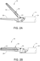
- FIGS. 1-2B show an exemplary ultrasonic surgical instrument (10) that includes a handle assembly (12), a shaft assembly (14) extending distally from handle assembly (12), and an end effector (16) arranged at a distal end of shaft assembly (14).
- Handle assembly (12) comprises a body (18) including a pistol grip (20) and energy control buttons (22) configured to be manipulated by a surgeon to control various aspects of tissue treatment energy delivered by surgical instrument (10).
- a trigger (24) is coupled to a lower portion of body (18) and is pivotable toward and away from pistol grip (20) to selectively actuate end effector (16).
- handle assembly (12) may comprise a scissor grip configuration, for example.
- Body (18) houses an ultrasonic transducer (26), shown schematically in FIG. 1 , configured to deliver ultrasonic energy to end effector (16), as described in greater detail below.
- Body (18) may also be referred to herein as a housing (18) and may include one component or an assembly of components.
- the terms “body” and “housing” are thus not intended to unnecessarily limit the invention described herein to any number of discrete components.
- end effector (16) includes an ultrasonic blade (28) and a clamp arm (30) configured to selectively pivot toward and away from ultrasonic blade (28) for clamping tissue therebetween.
- Clamp arm (30) includes a clamp pad (32) arranged on a clamping side thereof and is moveable from an open position shown in FIG. 2A to a closed position shown in FIG. 2B .
- ultrasonic blade (28) is acoustically coupled with ultrasonic transducer (26), which is configured to drive (i.e., vibrate) ultrasonic blade (28) at ultrasonic frequencies for cutting and/or sealing tissue positioned in contact with ultrasonic blade (28).
- Clamp arm (30) is operatively coupled with trigger (24) such that clamp arm (30) is configured to pivot toward ultrasonic blade (28), to the closed position, in response to pivoting of trigger (24) toward pistol grip (20). Further, clamp arm (30) is configured to pivot away from ultrasonic blade (28), to the open position in response to pivoting of trigger (24) away from pistol grip (20).
- trigger (24) Various suitable ways in which clamp arm (30) may be coupled with trigger (24) will be apparent to those of ordinary skill in the art in view of the teachings provided herein.
- one or more resilient members may be incorporated to bias clamp arm (30) and/or trigger (24) toward the open position.
- Shaft assembly (14) of the present example extends along a longitudinal axis and includes an outer tube (34), an inner tube (36) received within outer tube (34), and an ultrasonic waveguide (38) supported within and extending longitudinally through inner tube (36).
- Ultrasonic blade (28) is formed integrally with and extends distally from waveguide (38).
- a proximal end of clamp arm (30) is pivotally coupled to distal ends of outer and inner tubes (34, 36), enabling clamp arm (30) to pivot relative to shaft assembly (14) about a pivot axis defined by a pivot pin (40) ( see FIG. 2A ) extending transversely through the distal end of inner tube (36).
- inner tube (36) is longitudinally fixed relative to handle assembly (18), and outer tube (34) is configured to translate relative to inner tube (36) and handle assembly (18), along the longitudinal axis of shaft assembly (20).
- outer tube (34) translates distally, clamp arm (30) pivots about its pivot axis toward its open position.
- clamp arm (30) pivots about its pivot axis in an opposite direction toward its closed position.
- a proximal end of outer tube (34) is operatively coupled with trigger (24) such that actuation of trigger (24) causes translation of outer tube (34) relative to inner tube (36), thereby opening or closing clamp arm (30) as discussed above.
- outer tube (34) may be longitudinally fixed and inner tube (36) may be configured to translate for moving clamp arm (30) between the open and closed positions.
- inner tube (36) may be configured to translate for moving clamp arm (30) between the open and closed positions.
- Shaft assembly (14) and end effector (16) are configured to rotate together relative to body (18) about the longitudinal axis defined by shaft assembly (14).
- shaft assembly (14) further includes a rotation knob (42) arranged at a proximal end thereof.
- Rotation knob (42) is rotatably coupled to body (18) of handle assembly (12), and is rotationally fixed to outer tube (34), inner tube (36), and waveguide (38) by a coupling pin (not shown) extending transversely therethrough.
- Coupling pin (not shown) is arranged at a longitudinal location corresponding to an acoustic node of waveguide (38).
- rotation knob (42) may be rotationally fixed to the remaining components of shaft assembly (14) in various other manners.
- Rotation knob (42) is configured to be gripped by a user to selectively manipulate the rotational orientation of shaft assembly (14) and end effector (16) relative to handle assembly (12).
- Various examples of acoustic and mechanical connections between shaft assembly (14) and handle assembly (14) are described in greater detail in U.S. Pat. App. No. 15/644,930, entitled “Acoustic Drivetrain with External Collar at Nodal Position,” filed on July 10, 2017 and U.S. Pat. App. No. 15/644,944, entitled “Features to Couple Acoustic Drivetrain Components in Ultrasonic Surgical Instrument,” filed on July 10, 2017 .
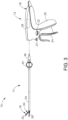
- FIGS. 3-5 show additional details of ultrasonic transducer (26) and waveguide (38).
- ultrasonic transducer (26) and waveguide (38) are configured to threadedly couple together.
- waveguide (38) is configured to acoustically couple ultrasonic transducer (26) with ultrasonic blade (28), and thereby communicate ultrasonic mechanical vibrations from ultrasonic transducer (26) to blade (28).
- ultrasonic transducer (26), waveguide (38), and ultrasonic blade (28) together define an acoustic assembly of ultrasonic surgical instrument (10).
- Ultrasonic transducer (26) is rotatably supported within body (18) of handle assembly (12), and is configured to rotate with shaft assembly (14), including waveguide (38), and end effector (16) about the longitudinal axis of shaft assembly (14).
- Ultrasonic transducer (26) is electrically coupled with a generator (not shown), which may be provided externally of ultrasonic surgical instrument (10) or integrated within surgical instrument (10).
- generator powers ultrasonic transducer (26) to produce ultrasonic mechanical vibrations, which are communicated distally through waveguide (38) to ultrasonic blade (28).
- Ultrasonic blade (28) is caused to oscillate longitudinally in the range of approximately 10 to 500 microns peak-to-peak, for example, and in some instances in the range of approximately 20 to 200 microns, at a predetermined vibratory frequency f o of approximately 50 kHz, for example.
- Vibrating ultrasonic blade (28) may be positioned in direct contact with tissue, with or without assistive clamping force provided by clamp arm (30), to impart ultrasonic vibrational energy to the tissue and thereby cut and/or seal the tissue.
- blade (28) may cut through tissue clamped between clamp arm (30) and a clamping side of blade (28), or blade (28) may cut through tissue positioned in contact with an oppositely disposed non-clamping side of blade (28) having an edge, for example during a "back-cutting" movement.
- waveguide (38) may be configured to amplify the ultrasonic vibrations delivered to blade (28).
- Waveguide (38) may include various features operable to control the gain of the vibrations, and/or features suitable to tune waveguide (38) to a selected resonant frequency.
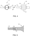
- ultrasonic transducer (26) includes a first resonator (or “end-bell”) (48), a conically shaped second resonator (or “fore-bell”) (50), and a transduction portion arranged between end-bell (48) and fore-bell (50) that includes a plurality of piezoelectric elements (52).
- a compression bolt extends distally, coaxially through end-bell (48) and piezoelectric elements (52), and is threadedly received within a proximal end of fore-bell (50).
- a velocity transformer extends distally from fore-bell (146) and includes an internally threaded bore (56) configured to receive and threadedly couple with an externally threaded proximal tip (58) of waveguide (38) as shown in FIGS. 4-5 .
- handle assembly (12) in the present example is reusable whereas shaft assembly (14) may be disconnected and replaced with an unused, replacement shaft assembly (14).
- one or more components of handle assembly (12) may be replaced after a predetermined number of use cycles of use for each respective patient treatment.
- ultrasonic transducer (26) may operate efficiently and effectively up to five use cycles, but performance may deteriorate beyond the five use cycles such that replacement of handle assembly (12) is desirable.
- integrated usage indicators (1116, 1216) may be used with any ultrasonic surgical instrument described above and below and in any of the various procedures described in the various patent references cited herein. To this end, like numbers below indicated like features described above. Other suitable ways in which various ultrasonic surgical instruments may be used will be apparent to those of ordinary skill in the art in view of the teachings herein.
- FIGS. 6-10B illustrate an exemplary ultrasonic surgical instrument (1110) having a handle assembly (1112) configured to be operated up to a predetermined number of use cycles, shaft assembly (14) configured for a single use cycle of treatment, and a first circuit usage indicator (1116).
- first circuit usage indicator (1116) is integrated into a housing (1118) of handle assembly (1112) for recording and indicating each respective use cycle of handle assembly (1112) in a use remaining state to a used state.
- First circuit usage indicator (1116) has a housing portion (1120) is configured to respond to a state of use that occurs once per usage cycle to thereby direct first circuit usage indicator (1116) toward the used state.
- first circuit usage indicator (1116) is directed toward the used state each time shaft assembly (14) is connected to handle assembly (1112). Once handle assembly (1112) has been repeatedly used with replacement shaft assemblies (14), first circuit usage indicator (1116) indicates the used state of handle assembly (1112) to the clinician. Such indication of first circuit usage indicator (1116) is visual as well as a lockout, which inhibits operation of handle assembly (1112).
- First circuit usage indicator (1116) includes a memory, such as an EEPROM (1122), and a circuit board (1124) having an electrical circuit (1126).
- EEPROM (1122) is configured to detect and record each instance that replacement shaft assemblies (14) are respectively connected to handle assembly (1112).
- Electrical circuit (1126) further includes a plurality of removable electrical connections (1128), such as wires, and a respective plurality of use tabs (1130) that cover openings (1132) on an outer surface of housing (1118) as shown in FIG. 8 .
- each use tab (1130) is pivotally connected to housing (1118) and further includes a wedge (1134) extending laterally into housing (1118) toward removable electrical connection (1128).
- the clinician manipulates one respective use tab (1130) inward through opening (1132) such that wedge (1134) breaks electrical connection (1124) for electrical removal from electrical circuit (1126).
- EEPROM (1122) adjusts electrical circuit (1126) based on each recorded connection of shaft assembly (14) to prevent electrical powering of ultrasonic transducer (26) handle assembly (1112) unless a subsequent use tab (1130) is depressed.
- EEPROM (1122) is thus configured to sense each respective electrical removal of use tabs (1130) and only allows electrical powering of ultrasonic transducer (26) after clinician removes electrical connection (1128) that correlates to the particular use cycle with replacement shaft assembly (14).
- each use tab (1130) has a respective counter indicia (1136) that increases in the proximal direction with numbers “1,” “2,” “3,” “4,” and “5" and are respectively configured to correspond to each replacement shaft assembly (14).
- a first counter indicia (1136) "1" indicates to the clinician that handle assembly (1212) is in its first use.
- EEPROM (1122) is further configured to inhibit further electrical powering of handle assembly (1112) with additional replacement shaft assemblies (14) greater than the predetermined number of use cycles.
- First circuit usage indicator (1116) is thereby configured to inhibit inadvertently using handle assembly (1112) beyond the predetermined number of use cycles.
- the clinician connects first replacement shaft assembly (14) to handle assembly (1112). Based on the recorded use cycles stored on EEPROM (1122), EEPROM prohibits electrical powering of handle assembly (1112) until the clinician depresses the respective use tab (1130) that correspond to the recorded use cycle and removes respective electrical connection (1128). Clinician depresses the respective use tab (1130) and thus treats the patient. Following treatment of the patient, shaft assembly (14) is disconnected from handle assembly (1112). Handle assembly (1112) is then prepped, such as by heating and/or sterilizing, for another surgical procedure and another replacement shaft assembly (14) is connected to handle assembly (1112). Such reuse continues in the remaining use state until all use tabs (1130) are depressed to the used state and EEPROM (1122) prohibits further electrical powering of handle assembly (1112).
- FIGS. 11A-12 An alternative, second circuit usage indicator (1216) is shown in FIGS. 11A-12 for use in handle assembly (1112) of FIG. 6 .
- Second circuit usage indicator (1216) is similar to first circuit usage indicator (1116) discussed above in most respects, but has a plurality of removable use tabs (1230) that include respective removable electrical connections (1228) of an electrical circuit (1226) integrated therein.
- Each removable use tab (1230) is thus configured to be pulled by the clinician and removed from housing (1118) to remove electrical connections (1228) for use by EEPROM (1122) as discussed above with respect to first circuit usage indicator (1116).
- Such tabs (1130, 1230) shown in FIGS. 6-12 may thus be movable between states for indication while remaining operatively connected to handle assembly (1112) or wholly removable from handle assembly (1112) for such indication.
- Versions of the devices described above may be designed to be disposed of after a single use, or they can be designed to be used multiple times. Versions may, in either or both cases, be reconditioned for reuse after at least one use. Reconditioning may include any combination of the steps of disassembly of the device, followed by cleaning or replacement of particular pieces, and subsequent reassembly. In particular, some versions of the device may be disassembled, and any number of the particular pieces or parts of the device may be selectively replaced or removed in any combination. Upon cleaning and/or replacement of particular parts, some versions of the device may be reassembled for subsequent use either at a reconditioning facility, or by a user immediately prior to a procedure.
- reconditioning of a device may utilize a variety of techniques for disassembly, cleaning/replacement, and reassembly. Use of such techniques, and the resulting reconditioned device, are all within the scope of the present disclosure.
- versions described herein may be sterilized before and/or after a procedure.
- the device is placed in a closed and sealed container, such as a plastic or TYVEK bag.
- the container and device may then be placed in a field of radiation that can penetrate the container, such as gamma radiation, x-rays, or high-energy electrons.
- the radiation may kill bacteria on the device and in the container.
- the sterilized device may then be stored in the sterile container for later use.
- a device may also be sterilized using any other technique known in the art, including but not limited to beta or gamma radiation, ethylene oxide, or steam.
Landscapes
- Health & Medical Sciences (AREA)
- Surgery (AREA)
- Engineering & Computer Science (AREA)
- Life Sciences & Earth Sciences (AREA)
- Heart & Thoracic Surgery (AREA)
- Nuclear Medicine, Radiotherapy & Molecular Imaging (AREA)
- Mechanical Engineering (AREA)
- Biomedical Technology (AREA)
- Dentistry (AREA)
- Medical Informatics (AREA)
- Molecular Biology (AREA)
- Animal Behavior & Ethology (AREA)
- General Health & Medical Sciences (AREA)
- Public Health (AREA)
- Veterinary Medicine (AREA)
- Surgical Instruments (AREA)
Description
-
US 2010/004669 A1 relates to a cordless hand-held ultrasonic cautery cutting device and method.US 5 313 935 A relates to an apparatus for counting the number of times a surgical instrument has been used. - Ultrasonic surgical instruments utilize ultrasonic energy for both precise cutting and controlled coagulation of tissue. The ultrasonic energy cuts and coagulates by vibrating a blade in contact with the tissue. Vibrating at frequencies of approximately 50 kilohertz (kHz), for example, the ultrasonic blade denatures protein in the tissue to form a sticky coagulum. Pressure exerted on the tissue with the blade surface collapses blood vessels and allows the coagulum to form a hemostatic seal. The precision of cutting and coagulation may be controlled by the surgeon's technique and adjusting the power level, blade edge, tissue traction, and blade pressure, for example.
- Examples of ultrasonic surgical devices include the HARMONIC ACE® Ultrasonic Shears, the HARMONIC WAVE® Ultrasonic Shears, the HARMONIC FOCUS® Ultrasonic Shears, and the HARMONIC SYNERGY® Ultrasonic Blades, all by Ethicon Endo-Surgery, Inc. of Cincinnati, Ohio. Further examples of such devices and related concepts are disclosed in
U.S. Pat. No. 5,322,055, entitled "Clamp Coagulator/Cutting System for Ultrasonic Surgical Instruments," issued Jun. 21, 1994 ;U.S. Pat. No. 5,873,873, entitled "Ultrasonic Clamp Coagulator Apparatus Having Improved Clamp Mechanism," issued Feb. 23, 1999 ;U.S. Pat. No. 5,980,510, entitled "Ultrasonic Clamp Coagulator Apparatus Having Improved Clamp Arm Pivot Mount," issued Nov. 9, 1999 ;U.S. Pat. No. 6,283,981, entitled "Method of Balancing Asymmetric Ultrasonic Surgical Blades," issued Sep. 4, 2001 U.S. Pat. No. 6,309,400, entitled "Curved Ultrasonic Blade having a Trapezoidal Cross Section," issued Oct. 30, 2001 ;U.S. Pat. No. 6,325,811, entitled "Blades with Functional Balance Asymmetries for use with Ultrasonic Surgical Instruments," issued Dec. 4, 2001 ;
U.S. Pat. No. 6,423,082, entitled "Ultrasonic Surgical Blade with Improved Cutting and Coagulation Features," issued Jul. 23, 2002 ;U.S. Pat. No. 6,773,444, entitled "Blades with Functional Balance Asymmetries for Use with Ultrasonic Surgical Instruments," issued Aug. 10, 2004 ;U.S. Pat. No. 6,783,524, entitled "Robotic Surgical Tool with Ultrasound Cauterizing and Cutting Instrument," issued Aug. 31, 2004 U.S. Pat. No. 8,057,498, entitled "Ultrasonic Surgical Instrument Blades," issued Nov. 15, 2011 ;U.S. Pat. No. 8,461,744, entitled "Rotating Transducer Mount for Ultrasonic Surgical Instruments," issued Jun. 11, 2013 , the disclosure of which is incorporated by reference herein;U.S. Pat. No. 8,591,536, entitled "Ultrasonic Surgical Instrument Blades," issued Nov. 26, 2013 ;U.S. Pat. No. 8,623,027, entitled "Ergonomic Surgical Instruments," issued Jan. 7, 2014 ;U.S. Pat. No. 9,095,367, entitled "Flexible Harmonic Waveguides/Blades for Surgical Instruments," issued Aug. 4, 2015 U.S. Pub. No. 2016/0022305, entitled "Ultrasonic Blade Overmold," published Jan. 28, 2016 . - An ultrasonic surgical instrument generally includes an ultrasonic transducer and an ultrasonic blade configured to be driven by the ultrasonic transducer. Various ultrasonic surgical instruments enable the ultrasonic blade to be selectively attached and detached from the ultrasonic transducer, via a threaded coupling between the two components. It is desirable to apply an appropriate amount of torque to this threaded coupling when assembling the blade with the transducer. Applying too much torque can cause the threaded coupling to fracture and fail during use, and applying too little torque can cause the threaded coupling to loosen and inhibit effective transmission of ultrasonic energy to tissue during use. Either result is undesirable, and can render the surgical instrument ineffective or entirely inoperable. Ultrasonic blades and transducers of conventional ultrasonic surgical instruments may be assembled with a hand-held torque wrench tool that is provided separately from the surgical instrument. The torque wrench tool includes features that limit application of additional torque to the threaded coupling between the ultrasonic blade and transducer once a predetermined amount of torque has been reached. An example of such a torque wrench tool is disclosed in
U.S. Pat. No. 5,059,210, entitled "Apparatus and Methods for Attaching and Detaching an Ultrasonic Actuated Blade/Coupler and an Acoustical Mount Therefor," issued Oct. 22, 1991 . -
US 2010/004669 A1 discloses an ultrasonic surgical instrument indicating the number of uses to an operator. - The accompanying drawings, which are incorporated in and constitute a part of this specification, illustrate embodiments of the invention, and, together with the general description of the invention given above, and the detailed description of the embodiments given below, serve to explain the principles of the present invention. The invention is defined by the appended claims.
-
FIG. 1 depicts a side view of a first exemplary ultrasonic surgical instrument having a handle assembly and a shaft assembly with an end effector; -
FIG. 2A depicts an enlarged side view of the end effector ofFIG. 1 in an open configuration; -
FIG. 2B depicts the enlarged side view of the end effector similar toFIG. 2A , but with the end effector in a closed configuration; -
FIG. 3 depicts a partially exploded side view of the ultrasonic surgical instrument ofFIG. 1 ; -
FIG. 4 depicts a partially schematic enlarged side view of an ultrasonic transducer, a waveguide, and a rotation knob of the ultrasonic surgical instrument ofFIG. 1 , showing attachment of the waveguide to the ultrasonic transducer; -
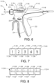
FIG. 5 depicts a partially schematic enlarged side view of a threaded coupling between the ultrasonic transducer and the waveguide ofFIG. 4 ; -
FIG. 6 depicts an enlarged side view of an eleventh exemplary ultrasonic surgical instrument having a first circuit usage indicator for a shaft assembly and a handle assembly; -
FIG. 7 depicts a side view of a circuit board of the first circuit usage indicator ofFIG. 6 having a plurality of use tabs; -
FIG 8 depicts a side view of the circuit board ofFIG. 7 with the plurality of use tabs hidden for greater clarity; -
FIG. 9A depicts an enlarged perspective view of the circuit board ofFIG. 7 with a first numeral usage tab in a use remaining position indicating a first usage is in use; -
FIG. 9B depicts the enlarged perspective view of the circuit board similar toFIG. 9A , but with the first use tab in a used position indicating the first usage is used; -
FIG. 10A depicts a sectional view of the circuit board taken along a centerline of the first use tab in the use remaining position ofFIG. 9A showing a closed-circuit portion; -
FIG. 10B depicts a sectional view of the circuit board taken along a centerline of the first use tab in the used position ofFIG. 9B showing an opened circuit portion; -
FIG. 11A depicts an enlarged perspective view of a second circuit usage indicator having a circuit board with a first use tab in a use remaining position indicating a first usage is in use; -
FIG. 11B depicts the enlarged perspective view of the circuit board similar toFIG. 11A , but with the first use tab removed thereby indicating the first usage is used; and -
FIG. 12 depicts a perspective view of the first numeral usage tab ofFIG. 11A . - The drawings are not intended to be limiting in any way, and it is contemplated that various embodiments of the invention may be carried out in a variety of other ways, including those not necessarily depicted in the drawings. The accompanying drawings incorporated in and forming a part of the specification illustrate several aspects of the present invention, and together with the description serve to explain the principles of the invention; it being understood, however, that this invention is not limited to the precise arrangements shown.
- The following description of certain examples of the invention should not be used to limit the scope of the present invention. The invention is defined by the appended claims. Other examples, features, aspects, embodiments, and advantages of the invention will become apparent to those skilled in the art from the following description, which is by way of illustration, one of the best modes contemplated for carrying out the invention. As will be realized, the invention is capable of other different and obvious aspects, all without departing from the invention. Accordingly, the drawings and descriptions should be regarded as illustrative in nature and not restrictive.
- For clarity of disclosure, the terms "proximal" and "distal" are defined herein relative to a surgeon, or other operator, grasping a surgical instrument having a distal surgical end effector. The term "proximal" refers to the position of an element arranged closer to the surgeon, and the term "distal" refers to the position of an element arranged closer to the surgical end effector of the surgical instrument and further away from the surgeon. Moreover, to the extent that spatial terms such as "upper," "lower," "vertical," "horizontal," or the like are used herein with reference to the drawings, it will be appreciated that such terms are used for exemplary description purposes only and are not intended to be limiting or absolute. In that regard, it will be understood that surgical instruments such as those disclosed herein may be used in a variety of orientations and positions not limited to those shown and described herein.
-
FIGS. 1-2B show an exemplary ultrasonic surgical instrument (10) that includes a handle assembly (12), a shaft assembly (14) extending distally from handle assembly (12), and an end effector (16) arranged at a distal end of shaft assembly (14). Handle assembly (12) comprises a body (18) including a pistol grip (20) and energy control buttons (22) configured to be manipulated by a surgeon to control various aspects of tissue treatment energy delivered by surgical instrument (10). A trigger (24) is coupled to a lower portion of body (18) and is pivotable toward and away from pistol grip (20) to selectively actuate end effector (16). In other suitable variations of surgical instrument (10), handle assembly (12) may comprise a scissor grip configuration, for example. Body (18) houses an ultrasonic transducer (26), shown schematically inFIG. 1 , configured to deliver ultrasonic energy to end effector (16), as described in greater detail below. Body (18) may also be referred to herein as a housing (18) and may include one component or an assembly of components. The terms "body" and "housing" are thus not intended to unnecessarily limit the invention described herein to any number of discrete components. - As shown best in
FIGS. 2A-2B , end effector (16) includes an ultrasonic blade (28) and a clamp arm (30) configured to selectively pivot toward and away from ultrasonic blade (28) for clamping tissue therebetween. Clamp arm (30) includes a clamp pad (32) arranged on a clamping side thereof and is moveable from an open position shown inFIG. 2A to a closed position shown inFIG. 2B . With respect toFIG. 3 , ultrasonic blade (28) is acoustically coupled with ultrasonic transducer (26), which is configured to drive (i.e., vibrate) ultrasonic blade (28) at ultrasonic frequencies for cutting and/or sealing tissue positioned in contact with ultrasonic blade (28). Clamp arm (30) is operatively coupled with trigger (24) such that clamp arm (30) is configured to pivot toward ultrasonic blade (28), to the closed position, in response to pivoting of trigger (24) toward pistol grip (20). Further, clamp arm (30) is configured to pivot away from ultrasonic blade (28), to the open position in response to pivoting of trigger (24) away from pistol grip (20). Various suitable ways in which clamp arm (30) may be coupled with trigger (24) will be apparent to those of ordinary skill in the art in view of the teachings provided herein. In some versions, one or more resilient members may be incorporated to bias clamp arm (30) and/or trigger (24) toward the open position. - Shaft assembly (14) of the present example extends along a longitudinal axis and includes an outer tube (34), an inner tube (36) received within outer tube (34), and an ultrasonic waveguide (38) supported within and extending longitudinally through inner tube (36). Ultrasonic blade (28) is formed integrally with and extends distally from waveguide (38). A proximal end of clamp arm (30) is pivotally coupled to distal ends of outer and inner tubes (34, 36), enabling clamp arm (30) to pivot relative to shaft assembly (14) about a pivot axis defined by a pivot pin (40) (see
FIG. 2A ) extending transversely through the distal end of inner tube (36). - In the present example, inner tube (36) is longitudinally fixed relative to handle assembly (18), and outer tube (34) is configured to translate relative to inner tube (36) and handle assembly (18), along the longitudinal axis of shaft assembly (20). As outer tube (34) translates distally, clamp arm (30) pivots about its pivot axis toward its open position. As outer tube (34) translates proximally, clamp arm (30) pivots about its pivot axis in an opposite direction toward its closed position. Though not shown, a proximal end of outer tube (34) is operatively coupled with trigger (24) such that actuation of trigger (24) causes translation of outer tube (34) relative to inner tube (36), thereby opening or closing clamp arm (30) as discussed above. In other suitable configurations not shown herein, outer tube (34) may be longitudinally fixed and inner tube (36) may be configured to translate for moving clamp arm (30) between the open and closed positions. Various other suitable mechanisms for actuating clamp arm (30) between the open and closed positions will be apparent to those of ordinary skill in the art.
- Shaft assembly (14) and end effector (16) are configured to rotate together relative to body (18) about the longitudinal axis defined by shaft assembly (14). As shown in
FIGS. 3-4 , shaft assembly (14) further includes a rotation knob (42) arranged at a proximal end thereof. Rotation knob (42) is rotatably coupled to body (18) of handle assembly (12), and is rotationally fixed to outer tube (34), inner tube (36), and waveguide (38) by a coupling pin (not shown) extending transversely therethrough. Coupling pin (not shown) is arranged at a longitudinal location corresponding to an acoustic node of waveguide (38). In other examples, rotation knob (42) may be rotationally fixed to the remaining components of shaft assembly (14) in various other manners. Rotation knob (42) is configured to be gripped by a user to selectively manipulate the rotational orientation of shaft assembly (14) and end effector (16) relative to handle assembly (12). Various examples of acoustic and mechanical connections between shaft assembly (14) and handle assembly (14) are described in greater detail inU.S. Pat. App. No. 15/644,930, entitled "Acoustic Drivetrain with External Collar at Nodal Position," filed on July 10, 2017 U.S. Pat. App. No. 15/644,944, entitled "Features to Couple Acoustic Drivetrain Components in Ultrasonic Surgical Instrument," filed on July 10, 2017 -
FIGS. 3-5 show additional details of ultrasonic transducer (26) and waveguide (38). In particular, ultrasonic transducer (26) and waveguide (38) are configured to threadedly couple together. Accordingly, waveguide (38) is configured to acoustically couple ultrasonic transducer (26) with ultrasonic blade (28), and thereby communicate ultrasonic mechanical vibrations from ultrasonic transducer (26) to blade (28). In this manner, ultrasonic transducer (26), waveguide (38), and ultrasonic blade (28) together define an acoustic assembly of ultrasonic surgical instrument (10). Ultrasonic transducer (26) is rotatably supported within body (18) of handle assembly (12), and is configured to rotate with shaft assembly (14), including waveguide (38), and end effector (16) about the longitudinal axis of shaft assembly (14). - Ultrasonic transducer (26) is electrically coupled with a generator (not shown), which may be provided externally of ultrasonic surgical instrument (10) or integrated within surgical instrument (10). During use, generator (not shown) powers ultrasonic transducer (26) to produce ultrasonic mechanical vibrations, which are communicated distally through waveguide (38) to ultrasonic blade (28). Ultrasonic blade (28) is caused to oscillate longitudinally in the range of approximately 10 to 500 microns peak-to-peak, for example, and in some instances in the range of approximately 20 to 200 microns, at a predetermined vibratory frequency fo of approximately 50 kHz, for example. Vibrating ultrasonic blade (28) may be positioned in direct contact with tissue, with or without assistive clamping force provided by clamp arm (30), to impart ultrasonic vibrational energy to the tissue and thereby cut and/or seal the tissue. For example, blade (28) may cut through tissue clamped between clamp arm (30) and a clamping side of blade (28), or blade (28) may cut through tissue positioned in contact with an oppositely disposed non-clamping side of blade (28) having an edge, for example during a "back-cutting" movement. In some versions, waveguide (38) may be configured to amplify the ultrasonic vibrations delivered to blade (28). Waveguide (38) may include various features operable to control the gain of the vibrations, and/or features suitable to tune waveguide (38) to a selected resonant frequency.
- In the present example, ultrasonic transducer (26) includes a first resonator (or "end-bell") (48), a conically shaped second resonator (or "fore-bell") (50), and a transduction portion arranged between end-bell (48) and fore-bell (50) that includes a plurality of piezoelectric elements (52). A compression bolt (not shown) extends distally, coaxially through end-bell (48) and piezoelectric elements (52), and is threadedly received within a proximal end of fore-bell (50). A velocity transformer (or "horn") (54) extends distally from fore-bell (146) and includes an internally threaded bore (56) configured to receive and threadedly couple with an externally threaded proximal tip (58) of waveguide (38) as shown in
FIGS. 4-5 . - While the teachings herein are disclosed in connection with ultrasonic surgical instruments, it will be appreciated that they may also be employed in connection with surgical instruments configured to provide a combination of ultrasonic and radio frequency (RF) energies. Examples of such instruments and related methods and concepts are disclosed in
U.S. Pat. No. 8,663,220, entitled "Ultrasonic Surgical Instruments," issued March 4, 2014 ;U.S. Pub. No. 2015/0141981, entitled "Ultrasonic Surgical Instrument with Electrosurgical Feature," published May 21, 2015 ; andU.S. Pub. No. 2017/0000541, entitled "Surgical Instrument with User Adaptable Techniques," published Jan. 5, 2017 - Given that various portions of ultrasonic surgical instrument (10) removably connect together, it may be desirable in various examples to reuse some portions of ultrasonic surgical instrument (10) while replacing others upon reconnection for further use by the surgeon. For example, handle assembly (12) in the present example is reusable whereas shaft assembly (14) may be disconnected and replaced with an unused, replacement shaft assembly (14). Despite the reusability of handle assembly (12), one or more components of handle assembly (12) may be replaced after a predetermined number of use cycles of use for each respective patient treatment. For example, ultrasonic transducer (26) may operate efficiently and effectively up to five use cycles, but performance may deteriorate beyond the five use cycles such that replacement of handle assembly (12) is desirable.
- While such reuse of handle assembly (12) followed by replacement of handle assembly (12) may be desirable, inhibiting reuse beyond the predetermined number of use cycles may be complicated, difficult, or tedious given that inspection of handle assembly (12) may not readily communicate the predetermined complete usage of handle assembly (12). An integrated usage indicator (1116, 1216) with a used state indicator as described below may thus be desirable in some instance for indicating usage to a clinician, such as the surgeon, without the need for manually tracking such usage separate from handle assembly (12). Once used state indicator indicates such use in a used state to the clinician, a replacement handle assembly (12) may be used for a following patient treatment. While various examples are given below regarding a particular number of uses and/or reuses, it will be appreciated that any number of uses and/or reuses may be possible in other examples. The invention is thus not intended to be unnecessarily limited to a particular number of uses and/or reuses.
- The following description provides various examples of integrated usage indicators (1116, 1216). Such integrated usage indicators (1116, 1216) described below may be used with any ultrasonic surgical instrument described above and below and in any of the various procedures described in the various patent references cited herein. To this end, like numbers below indicated like features described above. Other suitable ways in which various ultrasonic surgical instruments may be used will be apparent to those of ordinary skill in the art in view of the teachings herein.
-
FIGS. 6-10B illustrate an exemplary ultrasonic surgical instrument (1110) having a handle assembly (1112) configured to be operated up to a predetermined number of use cycles, shaft assembly (14) configured for a single use cycle of treatment, and a first circuit usage indicator (1116). With respect toFIGS. 6-7 , first circuit usage indicator (1116) is integrated into a housing (1118) of handle assembly (1112) for recording and indicating each respective use cycle of handle assembly (1112) in a use remaining state to a used state. First circuit usage indicator (1116) has a housing portion (1120) is configured to respond to a state of use that occurs once per usage cycle to thereby direct first circuit usage indicator (1116) toward the used state. In the present example, first circuit usage indicator (1116) is directed toward the used state each time shaft assembly (14) is connected to handle assembly (1112). Once handle assembly (1112) has been repeatedly used with replacement shaft assemblies (14), first circuit usage indicator (1116) indicates the used state of handle assembly (1112) to the clinician. Such indication of first circuit usage indicator (1116) is visual as well as a lockout, which inhibits operation of handle assembly (1112). - First circuit usage indicator (1116) includes a memory, such as an EEPROM (1122), and a circuit board (1124) having an electrical circuit (1126). EEPROM (1122) is configured to detect and record each instance that replacement shaft assemblies (14) are respectively connected to handle assembly (1112). Electrical circuit (1126) further includes a plurality of removable electrical connections (1128), such as wires, and a respective plurality of use tabs (1130) that cover openings (1132) on an outer surface of housing (1118) as shown in
FIG. 8 . - With respect to
FIG. 7 andFIGS. 9A-10B , each use tab (1130) is pivotally connected to housing (1118) and further includes a wedge (1134) extending laterally into housing (1118) toward removable electrical connection (1128). With each use, the clinician manipulates one respective use tab (1130) inward through opening (1132) such that wedge (1134) breaks electrical connection (1124) for electrical removal from electrical circuit (1126). EEPROM (1122) adjusts electrical circuit (1126) based on each recorded connection of shaft assembly (14) to prevent electrical powering of ultrasonic transducer (26) handle assembly (1112) unless a subsequent use tab (1130) is depressed. EEPROM (1122) is thus configured to sense each respective electrical removal of use tabs (1130) and only allows electrical powering of ultrasonic transducer (26) after clinician removes electrical connection (1128) that correlates to the particular use cycle with replacement shaft assembly (14). For visual indication of use cycles, each use tab (1130) has a respective counter indicia (1136) that increases in the proximal direction with numbers "1," "2," "3," "4," and "5" and are respectively configured to correspond to each replacement shaft assembly (14). For example, a first counter indicia (1136) "1" indicates to the clinician that handle assembly (1212) is in its first use. - Successive connections of replacement shaft assemblies (14) continue to require the clinician to remove respective electrical portions (1128) via depression of use tabs (1130) until a fifth counter indicia (1136) "5" is depressed to visually indicate the used state of handle assembly (1112). In addition, EEPROM (1122) is further configured to inhibit further electrical powering of handle assembly (1112) with additional replacement shaft assemblies (14) greater than the predetermined number of use cycles. First circuit usage indicator (1116) is thereby configured to inhibit inadvertently using handle assembly (1112) beyond the predetermined number of use cycles.
- In use, with respect to
FIGS. 9A-9B , the clinician connects first replacement shaft assembly (14) to handle assembly (1112). Based on the recorded use cycles stored on EEPROM (1122), EEPROM prohibits electrical powering of handle assembly (1112) until the clinician depresses the respective use tab (1130) that correspond to the recorded use cycle and removes respective electrical connection (1128). Clinician depresses the respective use tab (1130) and thus treats the patient. Following treatment of the patient, shaft assembly (14) is disconnected from handle assembly (1112). Handle assembly (1112) is then prepped, such as by heating and/or sterilizing, for another surgical procedure and another replacement shaft assembly (14) is connected to handle assembly (1112). Such reuse continues in the remaining use state until all use tabs (1130) are depressed to the used state and EEPROM (1122) prohibits further electrical powering of handle assembly (1112). - An alternative, second circuit usage indicator (1216) is shown in
FIGS. 11A-12 for use in handle assembly (1112) ofFIG. 6 . Second circuit usage indicator (1216) is similar to first circuit usage indicator (1116) discussed above in most respects, but has a plurality of removable use tabs (1230) that include respective removable electrical connections (1228) of an electrical circuit (1226) integrated therein. Each removable use tab (1230) is thus configured to be pulled by the clinician and removed from housing (1118) to remove electrical connections (1228) for use by EEPROM (1122) as discussed above with respect to first circuit usage indicator (1116). Such tabs (1130, 1230) shown inFIGS. 6-12 may thus be movable between states for indication while remaining operatively connected to handle assembly (1112) or wholly removable from handle assembly (1112) for such indication. - It should be understood that any one or more of the teachings, expressions, embodiments, examples, etc. described herein may be combined with any one or more of the other teachings, expressions, embodiments, examples, etc. that are described herein. The above-described teachings, expressions, embodiments, examples, etc. should therefore not be viewed in isolation relative to each other. Various suitable ways in which the teachings herein may be combined will be readily apparent to those of ordinary skill in the art in view of the teachings herein. Such modifications and variations are intended to be included within the scope of the claims.
- Versions of the devices described above may have application in conventional medical treatments and procedures conducted by a medical professional, as well as application in robotic-assisted medical treatments and procedures. By way of example only, various teachings herein may be readily incorporated into a robotic surgical system such as the DAVINCI™ system by Intuitive Surgical, Inc., of Sunnyvale, California. Similarly, those of ordinary skill in the art will recognize that various teachings herein may be readily combined with various teachings of any of the following:
U.S. Pat. No. 5,792,135, entitled "Articulated Surgical Instrument For Performing Minimally Invasive Surgery With Enhanced Dexterity and Sensitivity," issued Aug. 11, 1998 ;U.S. Pat. No. 5,817,084, entitled "Remote Center Positioning Device with Flexible Drive," issued Oct. 6, 1998 ;U.S. Pat. No. 5,878,193, entitled "Automated Endoscope System for Optimal Positioning," issued March 2, 1999 ,U.S. Pat. No. 6,231,565, entitled "Robotic Arm DLUS for Performing Surgical Tasks," issued May 15, 2001 ;U.S. Pat. No. 6,783,524, entitled "Robotic Surgical Tool with Ultrasound Cauterizing and Cutting Instrument," issued Aug. 31, 2004 ;U.S. Pat. No. 6,364,888, entitled "Alignment of Master and Slave in a Minimally Invasive Surgical Apparatus," issued April 2, 2002 ;U.S. Pat. No. 7,524,320, entitled "Mechanical Actuator Interface System for Robotic Surgical Tools," issued April 28, 2009 ;U.S. Pat. No. 7,691,098, entitled "Platform Link Wrist Mechanism," issued April 6, 2010 ;U.S. Pat. No. 7,806,891, entitled "Repositioning and Reorientation of Master/Slave Relationship in Minimally Invasive Telesurgery," issued Oct. 5, 2010 ;U.S. Pat. No. 8,844,789, entitled "Automated End Effector Component Reloading System for Use with a Robotic System," issued Sept. 30, 2014 ;U.S. Pat. No. 8,820,605, entitled "Robotically-Controlled Surgical Instruments," issued Sept. 2, 2014 ;U.S. Pat. No. 8,616,431, entitled "Shiftable Drive Interface for Robotically-Controlled Surgical Tool," issued Dec. 31, 2013 ;U.S. Pat. No. 8,573,461, entitled "Surgical Stapling Instruments with Cam-Driven Staple Deployment Arrangements," issued Nov. 5, 2013 ;U.S. Pat. No. 8,602,288, entitled "Robotically-Controlled Motorized Surgical End Effector System with Rotary Actuated Closure Systems Having Variable Actuation Speeds," issued Dec. 10, 2013 ;U.S. Pat. No. 9,301,759, entitled "Robotically-Controlled Surgical Instrument with Selectively Articulatable End Effector," issued April 5, 2016 U.S. Pat. No. 8,783,541, entitled "Robotically-Controlled Surgical End Effector System," issued July 22, 2014 ;U.S. Pat. No. 8,479,969, entitled "Drive Interface for Operably Coupling a Manipulatable Surgical Tool to a Robot," issued July 9, 2013 ;U.S. Pat. Pub. No. 8,800,838, entitled "Robotically-Controlled Cable-Based Surgical End Effectors," issued Aug. 12, 2014 ; and/orU.S. Pat. No. 8,573,465, entitled "Robotically-Controlled Surgical End Effector System with Rotary Actuated Closure Systems," issued Nov. 5, 2013 . - Versions of the devices described above may be designed to be disposed of after a single use, or they can be designed to be used multiple times. Versions may, in either or both cases, be reconditioned for reuse after at least one use. Reconditioning may include any combination of the steps of disassembly of the device, followed by cleaning or replacement of particular pieces, and subsequent reassembly. In particular, some versions of the device may be disassembled, and any number of the particular pieces or parts of the device may be selectively replaced or removed in any combination. Upon cleaning and/or replacement of particular parts, some versions of the device may be reassembled for subsequent use either at a reconditioning facility, or by a user immediately prior to a procedure. Those skilled in the art will appreciate that reconditioning of a device may utilize a variety of techniques for disassembly, cleaning/replacement, and reassembly. Use of such techniques, and the resulting reconditioned device, are all within the scope of the present disclosure.
- By way of example only, versions described herein may be sterilized before and/or after a procedure. In one sterilization technique, the device is placed in a closed and sealed container, such as a plastic or TYVEK bag. The container and device may then be placed in a field of radiation that can penetrate the container, such as gamma radiation, x-rays, or high-energy electrons. The radiation may kill bacteria on the device and in the container. The sterilized device may then be stored in the sterile container for later use. A device may also be sterilized using any other technique known in the art, including but not limited to beta or gamma radiation, ethylene oxide, or steam.
- Having shown and described various embodiments of the present invention, further adaptations of the methods and systems described herein may be accomplished by appropriate modifications by one of ordinary skill in the art without departing from the scope of the present invention. Several of such potential modifications have been mentioned, and others will be apparent to those skilled in the art. For instance, the examples, embodiments, geometrics, materials, dimensions, ratios, steps, and the like discussed above are illustrative and are not required. Accordingly, the scope of the present invention should be considered in terms of the following claims and is understood not to be limited to the details of structure and operation shown and described in the specification and drawings.
Claims (3)
- An ultrasonic surgical instrument (1110), comprising:(a) a housing (1118) configured to removably connect to a shaft assembly (14);(b) an ultrasonic transducer (26) supported by the housing and having a transducer connector configured to connect to a waveguide for acoustically connecting the ultrasonic transducer to the waveguide, wherein the ultrasonic transducer is configured to be operated up to a predetermined number of use cycles; and(c) an integrated usage indicator (1116) operatively connected to the housing and including a used state indicator, wherein the used state indicator is configured to indicate to a clinician in a used state when the ultrasonic transducer has been operated at least the predetermined number of use cycles for limiting usage of the ultrasonic transducer to the predetermined number of use cycles;characterized in that the integrated usage indicator further includes an electrical circuit having a plurality of removable electrical connections (1128; 1228), wherein each of the plurality of removable electrical connections is configured to be removed with each respective predetermined number of use cycles until indication of the used state indicator.
- The ultrasonic surgical instrument of claim 1, wherein the integrated usage indicator is configured to inhibit activation of the ultrasonic transducer with the shaft assembly attached therewith for inhibiting usage of the ultrasonic transducer greater than the predetermined number of use cycles.
- A method of indicating a used state of an ultrasonic surgical instrument according to claim 1 or claim 2, the method comprising:(a) connecting the shaft assembly to the housing;(b) directing the integrated usage indicator from a use remaining state toward the used state; and(c) indicating the used state with the used state indicator to the clinician when the integrated usage indicator is in the used state.
Applications Claiming Priority (3)
| Application Number | Priority Date | Filing Date | Title |
|---|---|---|---|
| US15/664,244 US10561436B2 (en) | 2017-07-31 | 2017-07-31 | Surgical instrument use indicator |
| PCT/US2018/043625 WO2019027753A1 (en) | 2017-07-31 | 2018-07-25 | Surgical instrument use indicator |
| EP18752949.0A EP3661434B1 (en) | 2017-07-31 | 2018-07-25 | Surgical instrument use indicator |
Related Parent Applications (2)
| Application Number | Title | Priority Date | Filing Date |
|---|---|---|---|
| EP18752949.0A Division-Into EP3661434B1 (en) | 2017-07-31 | 2018-07-25 | Surgical instrument use indicator |
| EP18752949.0A Division EP3661434B1 (en) | 2017-07-31 | 2018-07-25 | Surgical instrument use indicator |
Publications (3)
| Publication Number | Publication Date |
|---|---|
| EP3827768A1 EP3827768A1 (en) | 2021-06-02 |
| EP3827768C0 EP3827768C0 (en) | 2024-06-05 |
| EP3827768B1 true EP3827768B1 (en) | 2024-06-05 |
Family
ID=63165503
Family Applications (2)
| Application Number | Title | Priority Date | Filing Date |
|---|---|---|---|
| EP18752949.0A Active EP3661434B1 (en) | 2017-07-31 | 2018-07-25 | Surgical instrument use indicator |
| EP20209169.0A Active EP3827768B1 (en) | 2017-07-31 | 2018-07-25 | Surgical instrument use indicator |
Family Applications Before (1)
| Application Number | Title | Priority Date | Filing Date |
|---|---|---|---|
| EP18752949.0A Active EP3661434B1 (en) | 2017-07-31 | 2018-07-25 | Surgical instrument use indicator |
Country Status (5)
| Country | Link |
|---|---|
| US (4) | US10561436B2 (en) |
| EP (2) | EP3661434B1 (en) |
| JP (1) | JP7167128B2 (en) |
| CN (1) | CN111107798B (en) |
| WO (1) | WO2019027753A1 (en) |
Families Citing this family (35)
| Publication number | Priority date | Publication date | Assignee | Title |
|---|---|---|---|---|
| US8182501B2 (en) | 2004-02-27 | 2012-05-22 | Ethicon Endo-Surgery, Inc. | Ultrasonic surgical shears and method for sealing a blood vessel using same |
| ES2598134T3 (en) | 2004-10-08 | 2017-01-25 | Ethicon Endo-Surgery, Llc | Ultrasonic surgical instrument |
| US20070191713A1 (en) | 2005-10-14 | 2007-08-16 | Eichmann Stephen E | Ultrasonic device for cutting and coagulating |
| US7621930B2 (en) | 2006-01-20 | 2009-11-24 | Ethicon Endo-Surgery, Inc. | Ultrasound medical instrument having a medical ultrasonic blade |
| US8057498B2 (en) | 2007-11-30 | 2011-11-15 | Ethicon Endo-Surgery, Inc. | Ultrasonic surgical instrument blades |
| US8808319B2 (en) | 2007-07-27 | 2014-08-19 | Ethicon Endo-Surgery, Inc. | Surgical instruments |
| US8523889B2 (en) | 2007-07-27 | 2013-09-03 | Ethicon Endo-Surgery, Inc. | Ultrasonic end effectors with increased active length |
| US9044261B2 (en) | 2007-07-31 | 2015-06-02 | Ethicon Endo-Surgery, Inc. | Temperature controlled ultrasonic surgical instruments |
| US8512365B2 (en) | 2007-07-31 | 2013-08-20 | Ethicon Endo-Surgery, Inc. | Surgical instruments |
| US8430898B2 (en) | 2007-07-31 | 2013-04-30 | Ethicon Endo-Surgery, Inc. | Ultrasonic surgical instruments |
| US10010339B2 (en) | 2007-11-30 | 2018-07-03 | Ethicon Llc | Ultrasonic surgical blades |
| US8650728B2 (en) | 2009-06-24 | 2014-02-18 | Ethicon Endo-Surgery, Inc. | Method of assembling a transducer for a surgical instrument |
| US8951272B2 (en) | 2010-02-11 | 2015-02-10 | Ethicon Endo-Surgery, Inc. | Seal arrangements for ultrasonically powered surgical instruments |
| US9820768B2 (en) | 2012-06-29 | 2017-11-21 | Ethicon Llc | Ultrasonic surgical instruments with control mechanisms |
| US10226273B2 (en) | 2013-03-14 | 2019-03-12 | Ethicon Llc | Mechanical fasteners for use with surgical energy devices |
| US11020140B2 (en) | 2015-06-17 | 2021-06-01 | Cilag Gmbh International | Ultrasonic surgical blade for use with ultrasonic surgical instruments |
| US10357303B2 (en) | 2015-06-30 | 2019-07-23 | Ethicon Llc | Translatable outer tube for sealing using shielded lap chole dissector |
| US10245064B2 (en) | 2016-07-12 | 2019-04-02 | Ethicon Llc | Ultrasonic surgical instrument with piezoelectric central lumen transducer |
| US10842522B2 (en) | 2016-07-15 | 2020-11-24 | Ethicon Llc | Ultrasonic surgical instruments having offset blades |
| USD847990S1 (en) * | 2016-08-16 | 2019-05-07 | Ethicon Llc | Surgical instrument |
| US10779847B2 (en) | 2016-08-25 | 2020-09-22 | Ethicon Llc | Ultrasonic transducer to waveguide joining |
| US10952759B2 (en) | 2016-08-25 | 2021-03-23 | Ethicon Llc | Tissue loading of a surgical instrument |
| US10561436B2 (en) | 2017-07-31 | 2020-02-18 | Ethicon Llc | Surgical instrument use indicator |
| US11123095B2 (en) | 2019-04-30 | 2021-09-21 | Cilag Gmbh International | Blade grounding mechanisms and alternative pin designs |
| EP4125698A1 (en) * | 2020-04-02 | 2023-02-08 | Intuitive Surgical Operations, Inc. | Devices for instrument use recording, devices for recording instrument reprocessing events, and related systems and methods |
| CN112315549A (en) * | 2020-06-04 | 2021-02-05 | 赛诺微医疗科技(浙江)有限公司 | Connecting mechanism of ultrasonic knife and transducer and ultrasonic knife assembly adopting same |
| CN111678633A (en) * | 2020-07-09 | 2020-09-18 | 山东农业大学 | A shearing device for measuring the shearing force of a stem and a method of using the same |
| CN112386320B (en) * | 2020-12-04 | 2021-07-23 | 上海睿刀医疗科技有限公司 | A guide instrument box and a puncture guide and release mechanism |
| US11602344B2 (en) * | 2021-06-30 | 2023-03-14 | Covidien Lp | Surgical stapling apparatus with firing lockout assembly |
| CN114305694B (en) * | 2021-11-29 | 2023-07-14 | 上海微创医疗机器人(集团)股份有限公司 | Surgical instrument protection device, surgical instrument, mounting portion, and surgical instrument assembly |
| CN114176668B (en) * | 2021-12-31 | 2023-08-22 | 佗道医疗科技有限公司 | Indication mechanism for use condition of surgical instrument, use method and anti-counterfeiting method for surgical instrument |
| CN114948227B (en) * | 2022-06-13 | 2025-09-09 | 上海微创医疗机器人(集团)股份有限公司 | Safety protection device and instrument device |
| US12402966B2 (en) | 2023-03-27 | 2025-09-02 | Cilag Gmbh International | End of life indicators for robotic surgical instruments |
| TWI831671B (en) * | 2023-04-13 | 2024-02-01 | 炳碩生醫股份有限公司 | Surgical instrument and identification system for determining usage status of the same |
| WO2025097168A1 (en) * | 2023-11-02 | 2025-05-08 | Flexdex, Inc. | Surgical instrument assembly |
Family Cites Families (57)
| Publication number | Priority date | Publication date | Assignee | Title |
|---|---|---|---|---|
| US5318570A (en) * | 1989-01-31 | 1994-06-07 | Advanced Osseous Technologies, Inc. | Ultrasonic tool |
| US5059210A (en) | 1989-12-12 | 1991-10-22 | Ultracision Inc. | Apparatus and methods for attaching and detaching an ultrasonic actuated blade/coupler and an acoustical mount therefor |
| US5657429A (en) | 1992-08-10 | 1997-08-12 | Computer Motion, Inc. | Automated endoscope system optimal positioning |
| US5313935A (en) | 1992-12-31 | 1994-05-24 | Symbiosis Corporation | Apparatus for counting the number of times a surgical instrument has been used |
| US5322055B1 (en) | 1993-01-27 | 1997-10-14 | Ultracision Inc | Clamp coagulator/cutting system for ultrasonic surgical instruments |
| EP0699053B1 (en) | 1993-05-14 | 1999-03-17 | Sri International | Surgical apparatus |
| US5792135A (en) | 1996-05-20 | 1998-08-11 | Intuitive Surgical, Inc. | Articulated surgical instrument for performing minimally invasive surgery with enhanced dexterity and sensitivity |
| US6364888B1 (en) | 1996-09-09 | 2002-04-02 | Intuitive Surgical, Inc. | Alignment of master and slave in a minimally invasive surgical apparatus |
| US6331181B1 (en) | 1998-12-08 | 2001-12-18 | Intuitive Surgical, Inc. | Surgical robotic tools, data architecture, and use |
| US6231565B1 (en) | 1997-06-18 | 2001-05-15 | United States Surgical Corporation | Robotic arm DLUs for performing surgical tasks |
| US5980510A (en) | 1997-10-10 | 1999-11-09 | Ethicon Endo-Surgery, Inc. | Ultrasonic clamp coagulator apparatus having improved clamp arm pivot mount |
| US5873873A (en) | 1997-10-10 | 1999-02-23 | Ethicon Endo-Surgery, Inc. | Ultrasonic clamp coagulator apparatus having improved clamp mechanism |
| US6309400B2 (en) | 1998-06-29 | 2001-10-30 | Ethicon Endo-Surgery, Inc. | Curved ultrasonic blade having a trapezoidal cross section |
| CA2276316C (en) | 1998-06-29 | 2008-02-12 | Ethicon Endo-Surgery, Inc. | Method of balancing asymmetric ultrasonic surgical blades |
| US6459926B1 (en) | 1998-11-20 | 2002-10-01 | Intuitive Surgical, Inc. | Repositioning and reorientation of master/slave relationship in minimally invasive telesurgery |
| US6325811B1 (en) | 1999-10-05 | 2001-12-04 | Ethicon Endo-Surgery, Inc. | Blades with functional balance asymmetries for use with ultrasonic surgical instruments |
| US6423082B1 (en) | 2000-03-31 | 2002-07-23 | Ethicon Endo-Surgery, Inc. | Ultrasonic surgical blade with improved cutting and coagulation features |
| US6783524B2 (en) | 2001-04-19 | 2004-08-31 | Intuitive Surgical, Inc. | Robotic surgical tool with ultrasound cauterizing and cutting instrument |
| CA2792000C (en) | 2001-06-29 | 2016-08-16 | Intuitive Surgical, Inc. | Platform link wrist mechanism |
| US9060770B2 (en) | 2003-05-20 | 2015-06-23 | Ethicon Endo-Surgery, Inc. | Robotically-driven surgical instrument with E-beam driver |
| US8800838B2 (en) | 2005-08-31 | 2014-08-12 | Ethicon Endo-Surgery, Inc. | Robotically-controlled cable-based surgical end effectors |
| US7845537B2 (en) | 2006-01-31 | 2010-12-07 | Ethicon Endo-Surgery, Inc. | Surgical instrument having recording capabilities |
| US20110290856A1 (en) | 2006-01-31 | 2011-12-01 | Ethicon Endo-Surgery, Inc. | Robotically-controlled surgical instrument with force-feedback capabilities |
| US8992422B2 (en) | 2006-03-23 | 2015-03-31 | Ethicon Endo-Surgery, Inc. | Robotically-controlled endoscopic accessory channel |
| US20080097501A1 (en) | 2006-06-22 | 2008-04-24 | Tyco Healthcare Group Lp | Ultrasonic probe deflection sensor |
| US8684253B2 (en) | 2007-01-10 | 2014-04-01 | Ethicon Endo-Surgery, Inc. | Surgical instrument with wireless communication between a control unit of a robotic system and remote sensor |
| US8057498B2 (en) | 2007-11-30 | 2011-11-15 | Ethicon Endo-Surgery, Inc. | Ultrasonic surgical instrument blades |
| US8931682B2 (en) | 2007-06-04 | 2015-01-13 | Ethicon Endo-Surgery, Inc. | Robotically-controlled shaft based rotary drive systems for surgical instruments |
| CA2701962C (en) | 2007-10-05 | 2016-05-31 | Ethicon Endo-Surgery, Inc. | Ergonomic surgical instruments |
| US8435257B2 (en) * | 2007-12-03 | 2013-05-07 | Covidien Ag | Cordless hand-held ultrasonic cautery cutting device and method |
| US8573465B2 (en) | 2008-02-14 | 2013-11-05 | Ethicon Endo-Surgery, Inc. | Robotically-controlled surgical end effector system with rotary actuated closure systems |
| US9179912B2 (en) | 2008-02-14 | 2015-11-10 | Ethicon Endo-Surgery, Inc. | Robotically-controlled motorized surgical cutting and fastening instrument |
| US9386983B2 (en) | 2008-09-23 | 2016-07-12 | Ethicon Endo-Surgery, Llc | Robotically-controlled motorized surgical instrument |
| US8663220B2 (en) | 2009-07-15 | 2014-03-04 | Ethicon Endo-Surgery, Inc. | Ultrasonic surgical instruments |
| US8461744B2 (en) | 2009-07-15 | 2013-06-11 | Ethicon Endo-Surgery, Inc. | Rotating transducer mount for ultrasonic surgical instruments |
| US9168054B2 (en) * | 2009-10-09 | 2015-10-27 | Ethicon Endo-Surgery, Inc. | Surgical generator for ultrasonic and electrosurgical devices |
| US20110238063A1 (en) | 2010-03-29 | 2011-09-29 | Tyco Healthcare Group Lp | Method of Tracking Reposable Instrument Usage |
| US9072523B2 (en) * | 2010-11-05 | 2015-07-07 | Ethicon Endo-Surgery, Inc. | Medical device with feature for sterile acceptance of non-sterile reusable component |
| US20120191091A1 (en) | 2011-01-24 | 2012-07-26 | Tyco Healthcare Group Lp | Reusable Medical Device with Advanced Counting Capability |
| US9364278B2 (en) * | 2012-04-30 | 2016-06-14 | Covidien Lp | Limited reuse ablation needles and ablation devices for use therewith |
| US10492814B2 (en) * | 2012-07-09 | 2019-12-03 | Covidien Lp | Apparatus for endoscopic procedures |
| US9095367B2 (en) | 2012-10-22 | 2015-08-04 | Ethicon Endo-Surgery, Inc. | Flexible harmonic waveguides/blades for surgical instruments |
| US9468438B2 (en) * | 2013-03-01 | 2016-10-18 | Eticon Endo-Surgery, LLC | Sensor straightened end effector during removal through trocar |
| US9949785B2 (en) | 2013-11-21 | 2018-04-24 | Ethicon Llc | Ultrasonic surgical instrument with electrosurgical feature |
| US10010340B2 (en) * | 2014-02-28 | 2018-07-03 | Ethicon Llc | Ultrasonic surgical instrument with removable handle assembly |
| US20150297200A1 (en) * | 2014-04-17 | 2015-10-22 | Covidien Lp | End of life transmission system for surgical instruments |
| US10258363B2 (en) * | 2014-04-22 | 2019-04-16 | Ethicon Llc | Method of operating an articulating ultrasonic surgical instrument |
| US9750521B2 (en) | 2014-07-22 | 2017-09-05 | Ethicon Llc | Ultrasonic blade overmold |
| US20160066913A1 (en) * | 2014-09-05 | 2016-03-10 | Ethicon Endo-Surgery, Inc. | Local display of tissue parameter stabilization |
| BR112017018157B1 (en) * | 2015-02-27 | 2022-12-20 | Ethicon Llc | SURGICAL INSTRUMENT SYSTEM |
| US10182816B2 (en) * | 2015-02-27 | 2019-01-22 | Ethicon Llc | Charging system that enables emergency resolutions for charging a battery |
| US11141213B2 (en) | 2015-06-30 | 2021-10-12 | Cilag Gmbh International | Surgical instrument with user adaptable techniques |
| US10639059B2 (en) * | 2015-11-25 | 2020-05-05 | Ethicon Llc | Restricted usage features for surgical instrument |
| US10172684B2 (en) * | 2016-04-29 | 2019-01-08 | Ethicon Llc | Lifecycle monitoring features for surgical instrument |
| US10709470B2 (en) | 2017-07-10 | 2020-07-14 | Ethicon Llc | Features to couple acoustic drivetrain components in ultrasonic surgical instrument |
| US10813662B2 (en) | 2017-07-10 | 2020-10-27 | Ethicon Llc | Acoustic drivetrain with external collar at nodal position |
| US10561436B2 (en) | 2017-07-31 | 2020-02-18 | Ethicon Llc | Surgical instrument use indicator |
-
2017
- 2017-07-31 US US15/664,244 patent/US10561436B2/en active Active
-
2018
- 2018-07-25 CN CN201880060466.7A patent/CN111107798B/en active Active
- 2018-07-25 EP EP18752949.0A patent/EP3661434B1/en active Active
- 2018-07-25 JP JP2020505139A patent/JP7167128B2/en active Active
- 2018-07-25 EP EP20209169.0A patent/EP3827768B1/en active Active
- 2018-07-25 WO PCT/US2018/043625 patent/WO2019027753A1/en not_active Ceased
-
2019
- 2019-11-26 US US16/696,336 patent/US11464533B2/en active Active
-
2022
- 2022-07-08 US US17/860,241 patent/US12070239B2/en active Active
-
2024
- 2024-07-23 US US18/780,677 patent/US20240374280A1/en active Pending
Also Published As
| Publication number | Publication date |
|---|---|
| EP3661434B1 (en) | 2025-08-06 |
| EP3827768C0 (en) | 2024-06-05 |
| US10561436B2 (en) | 2020-02-18 |
| US20190029707A1 (en) | 2019-01-31 |
| JP7167128B2 (en) | 2022-11-08 |
| JP2020530788A (en) | 2020-10-29 |
| US12070239B2 (en) | 2024-08-27 |
| EP3827768A1 (en) | 2021-06-02 |
| EP3661434A1 (en) | 2020-06-10 |
| US20200170665A1 (en) | 2020-06-04 |
| CN111107798B (en) | 2024-01-30 |
| US11464533B2 (en) | 2022-10-11 |
| WO2019027753A1 (en) | 2019-02-07 |
| US20220395292A1 (en) | 2022-12-15 |
| EP3661434C0 (en) | 2025-08-06 |
| CN111107798A (en) | 2020-05-05 |
| US20240374280A1 (en) | 2024-11-14 |
Similar Documents
| Publication | Publication Date | Title |
|---|---|---|
| EP3827768B1 (en) | Surgical instrument use indicator | |
| EP3634271B1 (en) | Combination ultrasonic and electrosurgical system having generator filter circuitry | |
| US11607268B2 (en) | Surgical instruments | |
| US10420579B2 (en) | Surgical instruments | |
| EP4572689B1 (en) | Surgical instrument with clamp arm and pivot shaft hinge coupling |
Legal Events
| Date | Code | Title | Description |
|---|---|---|---|
| PUAI | Public reference made under article 153(3) epc to a published international application that has entered the european phase |
Free format text: ORIGINAL CODE: 0009012 |
|
| STAA | Information on the status of an ep patent application or granted ep patent |
Free format text: STATUS: THE APPLICATION HAS BEEN PUBLISHED |
|
| AC | Divisional application: reference to earlier application |
Ref document number: 3661434 Country of ref document: EP Kind code of ref document: P |
|
| AK | Designated contracting states |
Kind code of ref document: A1 Designated state(s): AL AT BE BG CH CY CZ DE DK EE ES FI FR GB GR HR HU IE IS IT LI LT LU LV MC MK MT NL NO PL PT RO RS SE SI SK SM TR |
|
| STAA | Information on the status of an ep patent application or granted ep patent |
Free format text: STATUS: REQUEST FOR EXAMINATION WAS MADE |
|
| 17P | Request for examination filed |
Effective date: 20211202 |
|
| RBV | Designated contracting states (corrected) |
Designated state(s): AL AT BE BG CH CY CZ DE DK EE ES FI FR GB GR HR HU IE IS IT LI LT LU LV MC MK MT NL NO PL PT RO RS SE SI SK SM TR |
|
| STAA | Information on the status of an ep patent application or granted ep patent |
Free format text: STATUS: EXAMINATION IS IN PROGRESS |
|
| 17Q | First examination report despatched |
Effective date: 20230208 |
|
| GRAP | Despatch of communication of intention to grant a patent |
Free format text: ORIGINAL CODE: EPIDOSNIGR1 |
|
| STAA | Information on the status of an ep patent application or granted ep patent |
Free format text: STATUS: GRANT OF PATENT IS INTENDED |
|
| RIC1 | Information provided on ipc code assigned before grant |
Ipc: A61B 17/29 20060101ALN20231208BHEP Ipc: A61B 17/32 20060101AFI20231208BHEP |
|
| INTG | Intention to grant announced |
Effective date: 20240109 |
|
| GRAS | Grant fee paid |
Free format text: ORIGINAL CODE: EPIDOSNIGR3 |
|
| GRAA | (expected) grant |
Free format text: ORIGINAL CODE: 0009210 |
|
| STAA | Information on the status of an ep patent application or granted ep patent |
Free format text: STATUS: THE PATENT HAS BEEN GRANTED |
|
| AC | Divisional application: reference to earlier application |
Ref document number: 3661434 Country of ref document: EP Kind code of ref document: P |
|
| AK | Designated contracting states |
Kind code of ref document: B1 Designated state(s): AL AT BE BG CH CY CZ DE DK EE ES FI FR GB GR HR HU IE IS IT LI LT LU LV MC MK MT NL NO PL PT RO RS SE SI SK SM TR |
|
| REG | Reference to a national code |
Ref country code: CH Ref legal event code: EP |
|
| REG | Reference to a national code |
Ref country code: DE Ref legal event code: R096 Ref document number: 602018070438 Country of ref document: DE |
|
| REG | Reference to a national code |
Ref country code: IE Ref legal event code: FG4D |
|
| U01 | Request for unitary effect filed |
Effective date: 20240614 |
|
| U07 | Unitary effect registered |
Designated state(s): AT BE BG DE DK EE FI FR IT LT LU LV MT NL PT SE SI Effective date: 20240625 |
|
| U20 | Renewal fee for the european patent with unitary effect paid |
Year of fee payment: 7 Effective date: 20240627 |
|
| PG25 | Lapsed in a contracting state [announced via postgrant information from national office to epo] |
Ref country code: HR Free format text: LAPSE BECAUSE OF FAILURE TO SUBMIT A TRANSLATION OF THE DESCRIPTION OR TO PAY THE FEE WITHIN THE PRESCRIBED TIME-LIMIT Effective date: 20240605 |
|
| PG25 | Lapsed in a contracting state [announced via postgrant information from national office to epo] |
Ref country code: GR Free format text: LAPSE BECAUSE OF FAILURE TO SUBMIT A TRANSLATION OF THE DESCRIPTION OR TO PAY THE FEE WITHIN THE PRESCRIBED TIME-LIMIT Effective date: 20240906 |
|
| PG25 | Lapsed in a contracting state [announced via postgrant information from national office to epo] |
Ref country code: ES Free format text: LAPSE BECAUSE OF FAILURE TO SUBMIT A TRANSLATION OF THE DESCRIPTION OR TO PAY THE FEE WITHIN THE PRESCRIBED TIME-LIMIT Effective date: 20240605 |
|
| PG25 | Lapsed in a contracting state [announced via postgrant information from national office to epo] |
Ref country code: NO Free format text: LAPSE BECAUSE OF FAILURE TO SUBMIT A TRANSLATION OF THE DESCRIPTION OR TO PAY THE FEE WITHIN THE PRESCRIBED TIME-LIMIT Effective date: 20240905 Ref country code: HR Free format text: LAPSE BECAUSE OF FAILURE TO SUBMIT A TRANSLATION OF THE DESCRIPTION OR TO PAY THE FEE WITHIN THE PRESCRIBED TIME-LIMIT Effective date: 20240605 Ref country code: GR Free format text: LAPSE BECAUSE OF FAILURE TO SUBMIT A TRANSLATION OF THE DESCRIPTION OR TO PAY THE FEE WITHIN THE PRESCRIBED TIME-LIMIT Effective date: 20240906 Ref country code: ES Free format text: LAPSE BECAUSE OF FAILURE TO SUBMIT A TRANSLATION OF THE DESCRIPTION OR TO PAY THE FEE WITHIN THE PRESCRIBED TIME-LIMIT Effective date: 20240605 Ref country code: RS Free format text: LAPSE BECAUSE OF FAILURE TO SUBMIT A TRANSLATION OF THE DESCRIPTION OR TO PAY THE FEE WITHIN THE PRESCRIBED TIME-LIMIT Effective date: 20240905 |
|
| PG25 | Lapsed in a contracting state [announced via postgrant information from national office to epo] |
Ref country code: PL Free format text: LAPSE BECAUSE OF FAILURE TO SUBMIT A TRANSLATION OF THE DESCRIPTION OR TO PAY THE FEE WITHIN THE PRESCRIBED TIME-LIMIT Effective date: 20240605 |
|
| PG25 | Lapsed in a contracting state [announced via postgrant information from national office to epo] |
Ref country code: IS Free format text: LAPSE BECAUSE OF FAILURE TO SUBMIT A TRANSLATION OF THE DESCRIPTION OR TO PAY THE FEE WITHIN THE PRESCRIBED TIME-LIMIT Effective date: 20241005 |
|
| PG25 | Lapsed in a contracting state [announced via postgrant information from national office to epo] |
Ref country code: CZ Free format text: LAPSE BECAUSE OF FAILURE TO SUBMIT A TRANSLATION OF THE DESCRIPTION OR TO PAY THE FEE WITHIN THE PRESCRIBED TIME-LIMIT Effective date: 20240605 |
|
| PG25 | Lapsed in a contracting state [announced via postgrant information from national office to epo] |
Ref country code: RO Free format text: LAPSE BECAUSE OF FAILURE TO SUBMIT A TRANSLATION OF THE DESCRIPTION OR TO PAY THE FEE WITHIN THE PRESCRIBED TIME-LIMIT Effective date: 20240605 Ref country code: SK Free format text: LAPSE BECAUSE OF FAILURE TO SUBMIT A TRANSLATION OF THE DESCRIPTION OR TO PAY THE FEE WITHIN THE PRESCRIBED TIME-LIMIT Effective date: 20240605 |
|
| PG25 | Lapsed in a contracting state [announced via postgrant information from national office to epo] |
Ref country code: SM Free format text: LAPSE BECAUSE OF FAILURE TO SUBMIT A TRANSLATION OF THE DESCRIPTION OR TO PAY THE FEE WITHIN THE PRESCRIBED TIME-LIMIT Effective date: 20240605 |
|
| PG25 | Lapsed in a contracting state [announced via postgrant information from national office to epo] |
Ref country code: SM Free format text: LAPSE BECAUSE OF FAILURE TO SUBMIT A TRANSLATION OF THE DESCRIPTION OR TO PAY THE FEE WITHIN THE PRESCRIBED TIME-LIMIT Effective date: 20240605 Ref country code: SK Free format text: LAPSE BECAUSE OF FAILURE TO SUBMIT A TRANSLATION OF THE DESCRIPTION OR TO PAY THE FEE WITHIN THE PRESCRIBED TIME-LIMIT Effective date: 20240605 Ref country code: RO Free format text: LAPSE BECAUSE OF FAILURE TO SUBMIT A TRANSLATION OF THE DESCRIPTION OR TO PAY THE FEE WITHIN THE PRESCRIBED TIME-LIMIT Effective date: 20240605 Ref country code: PL Free format text: LAPSE BECAUSE OF FAILURE TO SUBMIT A TRANSLATION OF THE DESCRIPTION OR TO PAY THE FEE WITHIN THE PRESCRIBED TIME-LIMIT Effective date: 20240605 Ref country code: IS Free format text: LAPSE BECAUSE OF FAILURE TO SUBMIT A TRANSLATION OF THE DESCRIPTION OR TO PAY THE FEE WITHIN THE PRESCRIBED TIME-LIMIT Effective date: 20241005 Ref country code: CZ Free format text: LAPSE BECAUSE OF FAILURE TO SUBMIT A TRANSLATION OF THE DESCRIPTION OR TO PAY THE FEE WITHIN THE PRESCRIBED TIME-LIMIT Effective date: 20240605 |
|
| REG | Reference to a national code |
Ref country code: CH Ref legal event code: PL |
|
| PG25 | Lapsed in a contracting state [announced via postgrant information from national office to epo] |
Ref country code: MC Free format text: LAPSE BECAUSE OF FAILURE TO SUBMIT A TRANSLATION OF THE DESCRIPTION OR TO PAY THE FEE WITHIN THE PRESCRIBED TIME-LIMIT Effective date: 20240605 |
|
| PG25 | Lapsed in a contracting state [announced via postgrant information from national office to epo] |
Ref country code: MC Free format text: LAPSE BECAUSE OF FAILURE TO SUBMIT A TRANSLATION OF THE DESCRIPTION OR TO PAY THE FEE WITHIN THE PRESCRIBED TIME-LIMIT Effective date: 20240605 |
|
| PLBE | No opposition filed within time limit |
Free format text: ORIGINAL CODE: 0009261 |
|
| STAA | Information on the status of an ep patent application or granted ep patent |
Free format text: STATUS: NO OPPOSITION FILED WITHIN TIME LIMIT |
|
| PG25 | Lapsed in a contracting state [announced via postgrant information from national office to epo] |
Ref country code: CH Free format text: LAPSE BECAUSE OF NON-PAYMENT OF DUE FEES Effective date: 20240731 |
|
| 26N | No opposition filed |
Effective date: 20250306 |
|
| PGFP | Annual fee paid to national office [announced via postgrant information from national office to epo] |
Ref country code: GB Payment date: 20250605 Year of fee payment: 8 |
|
| U20 | Renewal fee for the european patent with unitary effect paid |
Year of fee payment: 8 Effective date: 20250606 |
|
| PG25 | Lapsed in a contracting state [announced via postgrant information from national office to epo] |
Ref country code: IE Free format text: LAPSE BECAUSE OF NON-PAYMENT OF DUE FEES Effective date: 20240725 |
|
| PG25 | Lapsed in a contracting state [announced via postgrant information from national office to epo] |
Ref country code: CY Free format text: LAPSE BECAUSE OF FAILURE TO SUBMIT A TRANSLATION OF THE DESCRIPTION OR TO PAY THE FEE WITHIN THE PRESCRIBED TIME-LIMIT; INVALID AB INITIO Effective date: 20180725 |
|
| PG25 | Lapsed in a contracting state [announced via postgrant information from national office to epo] |
Ref country code: HU Free format text: LAPSE BECAUSE OF FAILURE TO SUBMIT A TRANSLATION OF THE DESCRIPTION OR TO PAY THE FEE WITHIN THE PRESCRIBED TIME-LIMIT; INVALID AB INITIO Effective date: 20180725 |