EP3742998B1 - Enhanced needle array and therapies for tumor ablation - Google Patents
Enhanced needle array and therapies for tumor ablation Download PDFInfo
- Publication number
- EP3742998B1 EP3742998B1 EP19703626.2A EP19703626A EP3742998B1 EP 3742998 B1 EP3742998 B1 EP 3742998B1 EP 19703626 A EP19703626 A EP 19703626A EP 3742998 B1 EP3742998 B1 EP 3742998B1
- Authority
- EP
- European Patent Office
- Prior art keywords
- electrode
- electrodes
- shaft
- cannula
- tissue
- Prior art date
- Legal status (The legal status is an assumption and is not a legal conclusion. Google has not performed a legal analysis and makes no representation as to the accuracy of the status listed.)
- Active
Links
Images


Classifications
-
- A—HUMAN NECESSITIES
- A61—MEDICAL OR VETERINARY SCIENCE; HYGIENE
- A61B—DIAGNOSIS; SURGERY; IDENTIFICATION
- A61B18/00—Surgical instruments, devices or methods for transferring non-mechanical forms of energy to or from the body
- A61B18/04—Surgical instruments, devices or methods for transferring non-mechanical forms of energy to or from the body by heating
- A61B18/12—Surgical instruments, devices or methods for transferring non-mechanical forms of energy to or from the body by heating by passing a current through the tissue to be heated, e.g. high-frequency current
- A61B18/14—Probes or electrodes therefor
- A61B18/1482—Probes or electrodes therefor having a long rigid shaft for accessing the inner body transcutaneously in minimal invasive surgery, e.g. laparoscopy
-
- A—HUMAN NECESSITIES
- A61—MEDICAL OR VETERINARY SCIENCE; HYGIENE
- A61B—DIAGNOSIS; SURGERY; IDENTIFICATION
- A61B18/00—Surgical instruments, devices or methods for transferring non-mechanical forms of energy to or from the body
- A61B18/04—Surgical instruments, devices or methods for transferring non-mechanical forms of energy to or from the body by heating
- A61B18/12—Surgical instruments, devices or methods for transferring non-mechanical forms of energy to or from the body by heating by passing a current through the tissue to be heated, e.g. high-frequency current
- A61B18/14—Probes or electrodes therefor
- A61B18/1477—Needle-like probes
-
- A—HUMAN NECESSITIES
- A61—MEDICAL OR VETERINARY SCIENCE; HYGIENE
- A61M—DEVICES FOR INTRODUCING MEDIA INTO, OR ONTO, THE BODY; DEVICES FOR TRANSDUCING BODY MEDIA OR FOR TAKING MEDIA FROM THE BODY; DEVICES FOR PRODUCING OR ENDING SLEEP OR STUPOR
- A61M5/00—Devices for bringing media into the body in a subcutaneous, intra-vascular or intramuscular way; Accessories therefor, e.g. filling or cleaning devices, arm-rests
- A61M5/14—Infusion devices, e.g. infusing by gravity; Blood infusion; Accessories therefor
- A61M5/158—Needles for infusions; Accessories therefor, e.g. for inserting infusion needles, or for holding them on the body
-
- A—HUMAN NECESSITIES
- A61—MEDICAL OR VETERINARY SCIENCE; HYGIENE
- A61N—ELECTROTHERAPY; MAGNETOTHERAPY; RADIATION THERAPY; ULTRASOUND THERAPY
- A61N1/00—Electrotherapy; Circuits therefor
- A61N1/18—Applying electric currents by contact electrodes
- A61N1/32—Applying electric currents by contact electrodes alternating or intermittent currents
- A61N1/327—Applying electric currents by contact electrodes alternating or intermittent currents for enhancing the absorption properties of tissue, e.g. by electroporation
-
- A—HUMAN NECESSITIES
- A61—MEDICAL OR VETERINARY SCIENCE; HYGIENE
- A61B—DIAGNOSIS; SURGERY; IDENTIFICATION
- A61B18/00—Surgical instruments, devices or methods for transferring non-mechanical forms of energy to or from the body
- A61B2018/00005—Cooling or heating of the probe or tissue immediately surrounding the probe
- A61B2018/00011—Cooling or heating of the probe or tissue immediately surrounding the probe with fluids
- A61B2018/00029—Cooling or heating of the probe or tissue immediately surrounding the probe with fluids open
-
- A—HUMAN NECESSITIES
- A61—MEDICAL OR VETERINARY SCIENCE; HYGIENE
- A61B—DIAGNOSIS; SURGERY; IDENTIFICATION
- A61B18/00—Surgical instruments, devices or methods for transferring non-mechanical forms of energy to or from the body
- A61B2018/00053—Mechanical features of the instrument of device
- A61B2018/00107—Coatings on the energy applicator
-
- A—HUMAN NECESSITIES
- A61—MEDICAL OR VETERINARY SCIENCE; HYGIENE
- A61B—DIAGNOSIS; SURGERY; IDENTIFICATION
- A61B18/00—Surgical instruments, devices or methods for transferring non-mechanical forms of energy to or from the body
- A61B2018/00053—Mechanical features of the instrument of device
- A61B2018/00172—Connectors and adapters therefor
- A61B2018/00178—Electrical connectors
-
- A—HUMAN NECESSITIES
- A61—MEDICAL OR VETERINARY SCIENCE; HYGIENE
- A61B—DIAGNOSIS; SURGERY; IDENTIFICATION
- A61B18/00—Surgical instruments, devices or methods for transferring non-mechanical forms of energy to or from the body
- A61B2018/00315—Surgical instruments, devices or methods for transferring non-mechanical forms of energy to or from the body for treatment of particular body parts
- A61B2018/00547—Prostate
-
- A—HUMAN NECESSITIES
- A61—MEDICAL OR VETERINARY SCIENCE; HYGIENE
- A61B—DIAGNOSIS; SURGERY; IDENTIFICATION
- A61B18/00—Surgical instruments, devices or methods for transferring non-mechanical forms of energy to or from the body
- A61B2018/00571—Surgical instruments, devices or methods for transferring non-mechanical forms of energy to or from the body for achieving a particular surgical effect
- A61B2018/00577—Ablation
-
- A—HUMAN NECESSITIES
- A61—MEDICAL OR VETERINARY SCIENCE; HYGIENE
- A61B—DIAGNOSIS; SURGERY; IDENTIFICATION
- A61B18/00—Surgical instruments, devices or methods for transferring non-mechanical forms of energy to or from the body
- A61B2018/00571—Surgical instruments, devices or methods for transferring non-mechanical forms of energy to or from the body for achieving a particular surgical effect
- A61B2018/00613—Irreversible electroporation
-
- A—HUMAN NECESSITIES
- A61—MEDICAL OR VETERINARY SCIENCE; HYGIENE
- A61B—DIAGNOSIS; SURGERY; IDENTIFICATION
- A61B18/00—Surgical instruments, devices or methods for transferring non-mechanical forms of energy to or from the body
- A61B18/04—Surgical instruments, devices or methods for transferring non-mechanical forms of energy to or from the body by heating
- A61B18/12—Surgical instruments, devices or methods for transferring non-mechanical forms of energy to or from the body by heating by passing a current through the tissue to be heated, e.g. high-frequency current
- A61B18/14—Probes or electrodes therefor
- A61B2018/1405—Electrodes having a specific shape
- A61B2018/1425—Needle
- A61B2018/143—Needle multiple needles
-
- A—HUMAN NECESSITIES
- A61—MEDICAL OR VETERINARY SCIENCE; HYGIENE
- A61B—DIAGNOSIS; SURGERY; IDENTIFICATION
- A61B18/00—Surgical instruments, devices or methods for transferring non-mechanical forms of energy to or from the body
- A61B18/04—Surgical instruments, devices or methods for transferring non-mechanical forms of energy to or from the body by heating
- A61B18/12—Surgical instruments, devices or methods for transferring non-mechanical forms of energy to or from the body by heating by passing a current through the tissue to be heated, e.g. high-frequency current
- A61B18/14—Probes or electrodes therefor
- A61B2018/1475—Electrodes retractable in or deployable from a housing
Definitions
- Cryoablation and thermal ablation use cold and heat, for example, to destroy tissue.
- Thermal ablation can be effective and very useful, but has proven difficult to control, particularly in spatial terms.
- Thermal ablation is not particularly selective in terms of which tissue it will destroy, hampering post-therapy recovery as useful tissue structure such as vasculature is destroyed along with targeted tissue.
- Electroporation has been used in various forms to treat targeted tissue. Electroporation operates by applying electrical pulses that cause cell membranes to alter, creating pores. Above a first threshold electrical field, the cell membranes begin to form pores. Above a second, higher threshold field, those pores can become irreversible, leading to cell death. Thus there are two forms of electroporation, reversible electroporation and irreversible electroporation (IRE). Reversible electroporation can be used in conjunction with the infusion of drugs or other agents which pass through reversibly created pores, where the infused drug/agent then causes selective cell death, however, such added agents can have systemic side effects on the patient.
- New and alternative devices and methods of applying therapy are desired which can combine the beneficial uses of IRE and thermal ablation, as well as reversible electroporation.
- US 2011/238057 A1 relates to an energy delivery probe and method of treatment using an energy delivery probe.
- US 5 863 290 A relates to an RF treatment and ablation apparatus that includes a primary antenna inserted into or adjacent to a selected body mass, such as a tumor, with one or more side deployed secondary antennas that are electromagnetically coupled to the primary antenna.
- US 2005/267467 A1 discloses a conforming electrode catheter comprising a brush electrode having a plurality of flexible filaments or bristles for applying therapeutic energy to target tissue for the formation of spot or continuous linear lesions, cauterization, and desiccation.
- US 2012/053403 A1 relates to an ablation overtube, which includes a body having a proximal portion, a distal portion and a lumen extending at least partially therethrough.
- the present inventors have recognized, among other things, that a problem to be solved is a need for new devices that provide greater physician control over the shaping and use of electrical pulses for IRE and thermal ablation.
- the present invention provides devices that allow a physician to manipulate the exposed electrode surfaces on a tissue destruction apparatus.
- the present inventors have also recognized that it may be desirable for a physician to be able to combine IRE and one or more additional therapies such as thermal ablation and/or ablation through (or augmented by) the injection of fluids containing drugs, biologics, or other substances.
- a first illustrative, non-limiting example takes the form of a system for destruction of tissue comprising a cannula having a proximal end and a distal end and containing a plurality of tissue penetrating elongate electrodes therein, the electrodes being extendible beyond the distal end of the cannula; a shaft electrode disposed at a spacing from the distal end of the cannula, wherein the spacing distance is adjustable; electrical connectors including at least one electrical connector electrically coupled to at least one of the elongate electrodes, and at least one electrical connector electrically coupled to the shaft electrode; and a sheath movable relative to the shaft electrode and adapted to control exposure of the shaft electrode to patient tissue.
- the shaft electrode has a length
- the sheath may be moveable to control how much of the length of the shaft electrode is exposed.
- the shaft electrode extends radially about a portion of the cannula, and the sheath may be moveable to control radial exposure of the shaft electrode.
- the cannula may include a fluid delivery lumen and a distal portion of the cannula may comprise one or more apertures for fluid infusion.
- the one or more apertures for fluid infusion are located on a first side of the cannula, and the shaft electrode is located on a second side of the cannula, such that the apertures and shaft electrode occupy opposing sides of the cannula within a single axial region of the cannula.
- At least one of the tissue penetrating elongate electrodes may comprise a fluid delivery lumen therethrough.
- At least one of the tissue penetrating elongate electrodes may comprise a dielectric coating on a first side of a portion thereof.
- the shaft electrode may be cylindrical and extend the entire way around the cannula.
- the shaft electrode may extend about only a portion of the cannula.
- the plurality of tissue penetrating electrodes may include at least a first tissue penetrating electrode having a first electrical connection and a second tissue penetrating electrode having a second electrical connection, wherein the first and second electrical connections are separately addressable.
- the sheath may be adapted to cover a radial portion of the shaft electrode to facilitate directional control of an output electrical field between a selected one or more of the first and second tissue penetrating electrodes and a portion of the shaft electrode.
- the plurality of tissue penetrating electrodes may include at least a first tissue penetrating electrode having a first mechanical coupling and a second tissue penetrating electrode having a second mechanical coupling, wherein the first and second mechanical couplings are separately actuatable to allow the first and second tissue penetrating electrodes to be advanced independent of one another.
- a second illustrative, non-limiting example takes the form of a system for destruction of tissue comprising: a cannula having a proximal end and a distal end and containing a plurality of tissue penetrating elongate electrodes therein, the electrodes being extendible beyond the distal end of the cannula; a shaft electrode disposed near die distal end of the cannula; and a plurality of electrical connectors including at least one electrical connector electrically coupled to at least one of the elongate electrodes, and at least one electrical connector electrically coupled to the shaft electrode; wherein the shaft electrode is disposed at a spacing distance from the distal end of the cannula, wherein the spacing distance is adjustable.
- the plurality of tissue penetrating electrodes may include at least a first tissue penetrating electrode having a first mechanical coupling and a second tissue penetrating electrode having a second mechanical coupling, wherein the first and second mechanical couplings are separately actuatable to allow the first and second tissue penetrating electrodes to be advanced independent of one another.
- a third illustrative, non-limiting example takes the form of a method of ablating a tissue region using a cannula having a shaft with proximal and distal ends, and one or more tissue penetrating electrodes passing through the shaft and moveable relative to the shaft, the method comprising: inserting the cannula to place the distal end of the shaft at a desired location near a target tissue; advancing at least one of the one or more tissue penetrating electrodes beyond the distal end of the shaft to pierce tissue; delivering a first waveform adapted to cause thermal ablation in a first region relatively nearer to the at least one tissue penetrating electrode; delivering a second waveform adapted to cause irreversible electroporation in a second region relatively more distant from the at least one tissue penetrating electrode.
- the shaft may have a shaft electrode thereon and the cannula comprises a sheath adapted to be moveable relative to the shaft to cover or uncover all or portions of the shaft electrode, and the method further comprises manipulating the sheath to expose a first area of the shaft electrode while the first waveform is delivered, and manipulating the sheath to expose a second area of the shaft electrode while the second waveform is delivered, wherein the first and second areas are different from one another, further wherein each of the first and second waveforms are delivered using at least one of the at least one tissue penetrating electrodes and the shaft electrode as opposing poles for an electrical output.
- the shaft may comprise a f l uid infusion lumen having an opening near the distal end thereof, and the method further comprises infusing a fluid through the fluid infusion lumen prior to delivering the first waveform, the fluid adapted to dampen a thermal effect of the first waveform for a first volume of tissue.
- the shaft may comprise a fluid infusion lumen having an opening near die distal end thereof, and the method further comprises infusing a fluid through the fluid infusion lumen prior to delivering the first waveform, the f l uid adapted to enhance a thermal effect of the first waveform for a first volume of tissue.
- the shaft may comprise a fluid infusion lumen having an opening near the distal end thereof, and the method further comprises infusing a fluid through the fluid infusion lumen prior to delivering the second waveform, the fluid adapted to enhance the electrical effect of the second waveform.
- the step of delivering the first waveform may be performed prior to delivering the second waveform.
- the step of delivering the first waveform may be performed after delivering the second waveform.
- the first and second waveforms may be each delivered repeatedly by alternating between the first and second waveforms.
- the first waveform may be delivered using a first of the at least one tissue penetrating electrodes
- the second waveform may be delivered using a second of the at least one tissue penetrating electrodes.
- the first waveform may be delivered repeatedly in a first therapy set
- the second waveform may be delivered repeatedly in a second waveform set.
- the method may further comprise repositioning the electrodes after the first therapy set and before the second therapy set.
- At least the second waveform may induce each of reversible and irreversible electroporation, and the method comprises infusing a f l uid adapted to cause cell death to a region affected by the reversible electroporation.
- the shaft may have a shaft electrode thereon and the cannula may comprise a sheath adapted to be moveable relative to the shaft to cover or uncover all or portions of the shaft electrode, wherein the method further comprises applying a grounding pad to the patient, wherein the first waveform is delivered using the grounding pad and at least one of the at least one tissue penetrating electrodes as the electrodes for therapy delivery, and the second waveform is delivered using the shaft electrode and at least one of the at least one tissue penetrating electrodes.
- the method may further comprise manipulating the sheath relative to the shaft electrode to expose or cover the shaft electrode between delivery of the first and second waveforms.
- the shaft may have a shaft electrode thereon and the cannula may comprise a sheath adapted to be moveable relative to the shaft to cover or uncover all or portions of the shaft electrode, and the method further comprises applying a grounding pad to the patient, wherein the first waveform is delivered using the shaft electrode and at least one of the at least one tissue penetrating electrodes, and the second waveform is delivered using the grounding pad and at least one of the at least one tissue penetrating electrodes as the electrodes for therapy delivery.
- the method may further comprise manipulating the sheath relative to the shaft electrode to expose or cover the shaft electrode between delivery of the first and second waveforms.
- a fourth illustrative, non-limiting example takes the form of a method of ablating a tissue region using a cannula having a shaft with proximal and distal ends, and one or more tissue penetrating electrodes passing through the shaft and moveable relative to the shaft, the method comprising: inserting the cannula to place the distal end of the shaft at a desired location near a target tissue; advancing at least one of the one or more tissue penetrating electrodes beyond the distal end of the shaft to pierce tissue; and delivering a waveform adapted to cause thermal ablation in a first region relatively nearer to the at least one tissue penetrating electrode and irreversible electroporation in a second region relatively more distant from the at least one tissue penetrating electrode.
- the step of delivering a waveform induces reversible electroporation in a third region and the method may further comprise infusing a fluid adapted to cause cell death to a region affected by the reversible electroporation.
- Figure 1 shows an approximation of different biophysical responses dependent on the amplitude-time relationship of delivered electrical pulses.
- the thresholds between cellular responses (10, 20, 30) operate generally as a function of the applied field strength and pulse duration. Below a first threshold 10, no effect occurs; between the first threshold 10 and a second threshold 20, reversible electroporation occurs. Above the second threshold 20, and below a third threshold 30, primarily irreversible electroporation (IRE) occurs. Above a third threshold 30, the effects begin to be primarily thermal. Thus, for example, at a given field strength and duration there may be no effect (location 12), and extending the duration of the field application can yield reversible electroporation (location 22), irreversible electroporation (location 32), and thermal ablation (location 40).
- a transmembrane potential in the range of about one volt is needed to cause reversible electroporation, however the relationship between pulse parameters such as timing and duration and the transmembrane potential required for reversible electroporation remains an actively investigated subject.
- the required field may vary depending on characteristics of the cells to be treated.
- reversible electroporation requires a voltage in the level of hundreds of volts per centimeter, with irreversible electroporation requiring a still higher voltage.
- the reversible electroporation threshold field strength may be about 360 V/cm, and the irreversible electroporation threshold field strength may be about 680 V/cm, as described in US Patent 8,048,067 .
- a plurality of individual pulses are delivered to obtain such effects across the majority of treated tissue; for example, 2, 4, 8, 16, or more pulses may be delivered.
- the field for electroporation has typically been applied by delivering a series of individual pulses each having a duration in the range of tens to hundreds of microseconds.
- US Patent 8,048,067 describes a series of eight 100 microsecond pulses delivered at 1 second intervals.
- the '067 patent describes analysis and experiments performed to illustrate that the area between lines 20 and 30 in Figure 1 actually exists, and that a non-thermal IRE method can be achieved.
- the tissue membrane does not return instantaneously, from a porated state.
- the application of pulses close together in time can have a cumulative effect as described, for example, in US Patent 8,926,606 .
- a series of pulses can be used to first porate a cell membrane and then move large molecules through generated, reversible pores, as described in US PG Patent App. Pub No. 2007/0025919 .
- While US Patent 8,048,067 discusses performing IRE without thermal effects, and US Patent 8,926,606 discusses achieving IRE without delivering pulses that exceed line 20 of Figure 1 and using cumulative effects of closely spaced pulses, die present invention in some examples is directed at the use of multiple regions of Figure 1 .
- a single device using either one output circuit having programmable or reconfigurable features, or a single device having a plurality of output circuits tuned to different regions (in terms of voltage, pulse width, or other parameters), may be used to purposefully deliver both thermal and non-thermal ablation therapies. Tuning and tailoring the outputs, including the use of different electrode combinations and therapy parameters, may allow thermal ablation in one spatial region and IRE or other ablation in a second spatial region.
- some examples are directed to new and distinct devices that can be manipulated and optimized for delivering therapy within any of the regions shown in Figure 1 . Still further examples combine these concepts to provide a device suited to delivering multiple and distinct therapies such as by achieving IRE pulses in one therapy regimen with a first device configuration, and achieving thermal effects in another therapy regimen using a second device configuration. Additional combinations and details are discussed below.
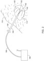
- Figure 2 shows a prior art "Leveen” needle.
- the device comprises an insertable portion 100 having a shaft 104 that extends to a plurality of tissue piercing electrodes 102 that can be extended or retracted once a target tissue 112 of a patient 110 is accessed.
- the proximal end of the apparatus is coupled by an electrical connection 106 to a power supply 108, which can be used to supply RF energy.
- the Leveen needle would be used to deliver thermal ablation to the target tissue.
- a return electrode in the form of a plate or plates may be provided on the patient's skin, a return electrode could be provided as another tissue piercing electrode, or a return electrode may be provided on the shaft 104 near its distal end, proximal of the tissue piercing electrodes 102.
- Enhancements on the original design can be found, for example, in US Patent 6,638,277 , which discusses independent actuation of the tissue piercing electrodes 102, both in terms of movement of the electrodes as well as separately electrically activating individual ones of the electrodes.
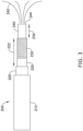
- FIGS 3-7 show illustrative example therapy apparatuses.
- a device 200 is shown having a main shaft portion 210, with a moveable insulative sheath 220 coaxially disposed therein.
- the sheath 220 partly surrounds an inner shaft 230 that carries a return electrode 232, which may be referred to herein also as a shaft electrode 232.
- the inner shaft surrounds a needle carrier 240 that has the tissue piercing electrodes 242 contained therein.
- the tissue piercing electrodes 242 are extendible beyond the distal end of the device 200, and particularly beyond the distal end of the inner shaft 230.
- the remaining elements that are exposed to the patient's tissue are generally not conductive, being formed, for example, of dielectric polymers; the electrodes may be for example, titanium, stainless steel, gold, or other conductive metals, for example. Those skilled in the art will recognize various materials that may be used in addition to those noted.
- the position of the return electrode 232 can be adjusted relative to the distal tip 244 of the needle carrier 240 as indicated at 234, so as to affect the resulting electric field distribution and corresponding tissue response.
- the distal tip 244 of the needle carrier 240 may be pointed or sharpened to allow it to pierce into the targeted tissue prior to advancement of the tissue piercing electrodes 242.
- the sheath 220 can be manipulated to advance or retract it relative to the return electrode 232.
- the return electrode 232 can be covered by the sheath 220 and thereby insulated from tissue to allow use in a unipolar mode, or may be partly covered by the sheath 220 to limit the exposed surface area of the return electrode 232.
- the distance between the return electrode and the distal end 244 of the needle carrier 240 may be manipulated as well.
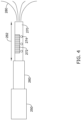
- Figure 4 shows another example.
- the device or cannula 250 includes a moveable sheath 260 that can be advanced or retracted as indicated at 262, as well as tissue piercing electrodes 280 which are again configured to be advanced and/or retracted beyond the distal end of the device or cannula 250 and in particular the needle carrier or inner shaft 270.
- the needle carrier or inner shaft 270 has a return electrode 272 (which may also be referred to as a shaft electrode) thereon on one side, and one or more fluid infusion apertures as shown at 274.
- the fluid infusion apertures 274 may be as shown, at about the same longitudinal location on the inner shaft 270 as the shaft electrode 272, or may be distal and/or proximal thereto, if desired.
- One or more lumens within the inner shaft 270 can be used to deliver fluid to the fluid infusion apertures 2 74.
- the shaft electrode 272 can be placed on one side of the device for use in generally single sided lesion formation, which is commonly used for example in prostate treatments where the therapy catheter is introduced next to, rather than into, the target tissue.
- one or more of the tissue piercing electrodes 280 may include a fluid lumen therein to allow delivery of a fluid through the tissue piercing electrodes 280.
- the tissue piercing electrodes may the take form of a hypotube.
- the fluid infusion apertures may be used to deliver a fluid that enhances the electrical conductivity of the surrounding tissue in some examples.
- a fluid may be infused that contains a drug, macromolecules, biologic, or other substance which will affect cell properties in one or more ways.
- macromolecules that disrupt cellular function may be injected, with the intent being to have cells uptake the macromolecules while porated to lead to cell death.
- a cationic polymer may be injected, which may increase the susceptibility of the cellular membrane to poration, as described in US Provisional Patent Application Serial No. 62/585,849 , titled IRREVERSIBLE ELECTROPORATION THROUGH A COMBINATION OF SUBSTANCE INJECTION AND ELECTRICAL FIELD APPLICATION.
- a fluid infusion may comprise saline, or may include dextrose, each of which will affect the conductivity of the surrounding tissue.
- saline enhances conductivity and dextrose reduces conductivity.
- a fluid may be infused that will limit the scope of therapeutic effect of a thermal or IRE therapy by, for example, cooling an area of tissue or limiting current flow or electrical field propagation.
- biocompatible mineral oil may be used, as it would limit electrical propagation by having non-conductive properties.
- a glycol mixture at a low concentration may be used to provide a combination of cooling and electrical resistance.
- distilled water may be infused, reducing ion concentration, or a reverse osmosis or ion-exchange may be used.
- a therapy apparatus may have a membrane facilitating reverse osmosis or ion exchange therethrough, reducing ion concentration and thereby increasing localized resistance.
- a cooling apparatus may be included, such as fluid pumping system, vaporizer or other apparatus, such as in US Patents 6,428,534 and 7,850,681 , as cooling reduces ion mobility. At least with fluid infusion examples, the delivery of such fluids can affect the ratio of extracellular to intracellular conductivity and thereby change the local electric field across a plasma membrane.
- Figure 5 shows another illustrative therapy apparatus.
- the device or cannula 300 has a moveable sheath 310 therein having a window as indicated at 312.
- the sheath 310 in this example can be moved longitudinally 314 as well as rotated 316 over the inner shaft 320 having electrodes 322, 324 thereon, where the electrodes 322, 324 may be separately addressable if desired.
- Tissue penetrating electrodes 326, 328 may again be configured to be advanced or retracted, individually or as a group, as desired, and may also be individually addressable electrodes for the device.
- the apparatus of Figure 5 may allow various combinations of electrodes for therapy delivery such as:
- the device or cannula 350 has a sheath 360 that may be manipulated relative to the inner shaft 370.
- the inner shaft 370 carries a shaft electrode at 372 and has fluid infusion apertures 374 that can be used to inject fluid 376.
- the tissue piercing electrode array 380 (which may be advanced or retracted individually or as a group, and which may be electrically addressed individually or in pairs, groups, subgroups or as an entire array) is further tailored to allow manipulation of electrode surface area.
- tissue piercing electrode 382 has a retractable insulative sheath 384 thereon, as does electrode 392.
- tissue piercing electrodes has a sheath extending over its entire length as indicated at 388, with the sheath 388 retractable as indicated at 386. Another of the tissue piercing electrodes is itself retracted as shown at 390.
- individual addressing allows separate field definition as indicated at 394 and 396, allowing greater targeting of the therapy field.
- the targeted and individualized fields 394, 396 may be used to deliver thermal ablation in a locally controlled space, while IRE is delivered in a therapy regimen that uses more of the tissue penetrating electrodes ganged together, for example. In this way, the thermal ablation can be targeted in areas where sensitive tissue is not present (such as vascular tissue), while IRE can be used more broadly to allow more selective killing of cells, if desired.
- FIG. 7 shows an illustrative system.
- the system 400 includes a therapy device 410 having a relatively complex handle structure including individual actuators 410 for manipulating the tissue piercing electrodes (individually, as groups, or as the entire array) at the distal tip of the apparatus, and a separate actuator 414 for controlling a sheath that selectively limits the exposed surface area of the return electrode.
- Electrical cord 416 couples to a signal generator 418, while a fluid coupling 420 is linked to a fluid source 422.
- the distal portion of the therapy device 410 is shown at 430 and may incorporate any of the designs in Figures 3-6 , above, or Figures 8-11 , below.
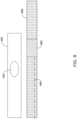
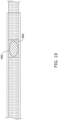
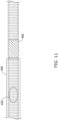
- FIGS 8-11 show an illustrative therapy apparatus with manipulation of an electrode.
- a sheath 450 is shown having a window at 452.
- the sheath may be, for example, a 0.13 mm (0.005 inch polyimide tube, though any design or material may be used instead of polyimide of such thickness; other insulative polymers may be used, for example.
- the inner shaft 460 carries shaft electrode 462.
- the shaft electrode may be, for example, a titanium or medical grade stainless steel element, and may be a ring electrode or a directional electrode as shown in examples above.
- a conductor 464 such as a stainless steel conductor, can be provided through shaft 460 which may be, for example, a multi-lumen tube of any suitable material such as polyimide, polyether block amide, or other suitable material.
- shaft 460 may be, for example, a multi-lumen tube of any suitable material such as polyimide, polyether block amide, or other suitable material.
- the sheath 450 may completely cover the electrode 462 by having the window 452 proximal of the electrode 462. Advancing the sheath 450 as shown in Figure 10 allows a selected and reduced area of the electrode 462 to be exposed through window 452. Retracting the sheath 450 as shown in Figure 11 allows the entire electrode 462 to be exposed.
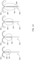
- Figures 12-13 show illustrative effects of different therapy modes with different electrode configurations.
- Figure 12 shows variation in IRE field strength with variation of shaft electrode length, using a homogenous medium model.
- a first example at 500 applies a 3000 volt output between a 2.5 mm shaft electrode 502 and tissue piercing electrodes 504, with the boundaries of the IRE field shown at 506.
- the output may be delivered for example as a series of 4 to 20 pulses (or more) with durations in the 0.1 to 100 microsecond range (or more) at a frequency of 1 to 100 Hz (or more or less), for example, 8 to 10 pulses of 5 microsecond duration at 10 Hz may be delivered.
- a second example at 520 assumes a 5 mm shaft electrode length 522.
- the IRE field boundary 526 closely envelopes the tissue piercing electrodes and can be seen to have widened and lengthened about the shaft electrode 522. Extending the shaft electrode 542 length to 10 mm, as shown at 540, again elongates the boundaries of the IRE field boundary 546; it can be seen also that the field span surrounding the tissue piercing electrodes 544 becomes larger as well.
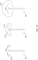
- FIG 13 shows thermal ablation boundaries using a monopolar configuration.
- a return plate electrode (not shown) is placed on the skin of the patient, typically using a hydrogel or the like to reduce tissue/electrode impedance, as the therapy device is used to deliver output therapy.
- the thermal ablation boundaries 604 are generally limited to the region of the tissue piercing electrodes. With increased voltage, as shown at 620 and 640, the thermal ablation region expands quickly to develop a volume around the tissue penetrating electrodes 622, 642.
- the shaft electrode size may be varied while a plurality of IRE treatments take place, wherein the individual IRE treatments comprise a plurality of applied pulses delivered as a set of therapy pulses, and wherein the shaft electrode size and usage is changed from one set to the next as by, for example, exposing more or less of the shaft electrode from one set to the next, or by switching from a monopolar to bipolar treatment mode by enabling or disabling the shaft electrode.
- thermal ablation modalities can be difficult to control due to heat sink effects of blood flow in nearby vasculature and/or the treatment device itself.
- tract seeding can be prevented by applying ablation therapy during retraction of the device to cause a thin layer of tissue necrosis along the tract.
- Application of IRE pulses in sets before or after the thermal treatment may target not only the tissue adjacent to the electrodes themselves, but also tissue that is located outside of the thermal treatment region between two electrodes.
- IRE and thermal treatments are combined into one overall therapy regimen as by, for example, alternating between pulses of longer duration (which generate thermal effects) and shorter duration (which generate IRE-type effects) within a therapy pulse set.
- an IRE output is generated after a thermal output and before adjustment of electrode position to target a different area of the anatomy; for example, a sequence of thermal output and IRE output may be followed by extending or retracting an electrode or insulator over an electrode, with the thermal output used to create larger volume effects and the IRE output used to eliminate possible tract seeding.
- IRE is used before thermal output.
- IRE can reduce impedance in affected tissue. By first reducing impedance, the thermal output of a subsequent stage can generate a greater quantity of thermal affect with reduced voltage output, as the lowered impedance allows higher current at a given voltage, where it is recognized that the square of the current yields the heating effect of a given therapy.
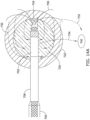
- FIGs 14A-B shows a tumor being treated by an illustrative device.
- a therapy device or cannula 700 has been inserted into a patient's tissue.
- a shaft electrode is shown at 702, with a moveable sheath 708 on the shaft as well to adjust the area of the electrode 702 that is exposed to patient tissue.
- a distal tip 704 of the cannula 700 has an angled or pointed end to allow passage through the patient tissue.
- the distal tip 704 is relatively sharp to allow it to pierce through tissue; such an example is shown in Figure 14A where the distal tip 704 has been used to pierce a tumor 720 and surrounding lesion 722.
- the distal tip 704 may be blunted to allow atraumatic passage through a body lumen such as a biliary duct, lymph vessel or duct, urethra, mammary duct, digestive passageway, blood vessel, or other body passageway, as the case may be.
- the distal tip 704 may be partly blunted to allow its use to separate body tissue layers as it passes, for example, alongside the outer capsule of a body organ such as the liver or kidney.
- a plurality of tissue piercing electrodes or needle electrodes are shown at 706.
- the cannula is inserted 700 far enough into the tumor to place the shaft electrode at least partly in the tumor, and the needle electrodes extend beyond the tumor and lesion.
- Tract seeding in this example may occur if abnormal cells from the tumor 720 stick to the needle electrodes 706 as they pass out through the lesion and into surrounding normal tissue, as well as by cells sticking to the main body of the cannula 700 such as sheath 708 and shaft electrode 702 during removal or repositioning maneuvers. In either event, the abnormal cells may be transported out of the tumor into surrounding tissue, and so an ablation or cell destruction therapy that destroys such cells in addition to die cells of the tumor 720 and surrounding lesion 722 is desirable.
- a plurality of distinct treatment steps take place using differing parameters and electrodes to account for both the extent of the tumor 720 and any potential tract seeding.
- currents 730 may be generated in a bipolar treatment stage or stages between one or more of the tissue piercing or needle electrodes 706 and the shaft electrode 702.
- Currents 732 may also be generated in one or more monopolar treatment stages between an external return electrode 740 and one or more of die needle electrodes 706.
- Currents 734 may be generated in one or more monopolar stages using the shaft electrode 702 and the external return electrode 740.
- the external return electrode 740 may be, for example, a grounding pad. The grounding pad or external return electrode 740 may be placed in different positions for different steps, to direct the electrical field in different directions, if desired.
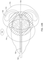
- Figure 14B illustrates results of several therapy steps using distinct therapy modalities.
- a first lesion field is generated at 770 by the use of a monopolar thermal or IRE therapy delivery using the needle electrodes 706 and an external return electrode 740.
- a second lesion field is generated at 772 by the use of a bipolar IRE or thermal therapy using most or all of the shaft electrode 702 as one pole and one or more of the needle electrodes 706 as opposing pole(s).
- a third lesion field is generated at 774 using a monopolar IRE or thermal therapy delivered using a portion of the shaft electrode 702 (for example, a lesser extent of the shaft electrode 702 may be exposed during such delivery than is shown in Figure 14B ) and an external return electrode 740.
- only two such fields may be generated in some examples.
- the present invention encompasses each combination of the two monopolar and bipolar therapy modes, in either IRE or thermal formats, in any desired order.
- the skilled person can readily generate the complete matrix.
- the "IRE" therapy steps may have thermal effects as well, but predominantly use IRE to cause cell death; likewise, the predominant mode of cell death for the "Thermal" therapy steps will be thermal though IRE may occur in some cells as well.
- Factors that may differentiate Thermal from IRE therapy may include duty cycle and field strength or amplitude. Determination of whether thermal or IRE therapy has been effective can be determined through staining using immune-histo-chemical assays, which will illustrate differentiation between tissue regions subject to different types of cell death. For example, immunological response to IRE-cause cell death is distinguishable from that for thermally destroyed cells; cells that survive and/or are only subject to reversible electroporation will further show a demarcation.
- an additional therapy mode may comprise placing the shaft electrode 702 (or a portion thereof) electrically in common with one or more of the needle electrodes in a monopolar therapy mode, whether for IRE or thermal ablation.
- a monopolar therapy mode is used for thermal ablation using a lower voltage gradient
- a bipolar therapy mode is used for IRE using a higher voltage gradient.
- two electrodes 2.5 cm apart can use a 2000 volt output to exceed 650 V/cm field for IRE, while two electrodes 10 cm apart using 1000 volt output will yield a 100 V/cm field, which is sufficient to attain thermal effects if using longer pulse widths and/or a higher duty cycle, with the combination reducing damage or excitation on distant muscle or nerve fibers of the patient in either case.
- the pulse-duration and field strength relationship with thermal damage and irreversible electroporation induction is harnessed to produce a therapeutic effect with desirable damage modes.
- FIG. 15 is a block flow diagram illustrating various examples.
- the overall method 800 may be subject to a number of repetitions, both internally within the method and as separate steps in a procedure to treat a patient.
- a therapy device is inserted at 810. Insertion 810 may make use of an existing lumen or channel of the patient (such as using a blood vessel or other duct/vessel in the patient) or may comprise piercing tissue with an instrument designed for such piercing.
- the treatment apparatus may deploy one or more electrodes, as indicated at 820.
- tissue piercing electrodes such as in the modified Leveen-style devices shown above, may be extended out of internal lumens of the therapy device to pierce tissue or otherwise position electrodes for use.
- a therapy is then delivered, as indicated at 830.
- the therapy may be, for example, an IRE therapy 832 in which monophasic or biphasic (or triphasic or other multiphasic) electrical output is generated with relatively high amplitudes (yielding fields of over 600 V/cm, for example) and short pulsewidths (for example in the range of 0.1 to 100 microseconds) at a relatively lower duty cycle (such as 1 to 100 Hz - such as a duty cycle of less than 0.1%), which may avoid thermal heating to yield predominantly IRE therapy.
- the therapy may include injection of a fluid to enhance or modify effectiveness or spatial effects of an applied electrical therapy, or may instead be injection of an ablative fluid such as a fluid having limited caustic effects, or cooling or heating effects, as indicated at 834.
- the therapy may be a thermal treatment, which may incorporate somewhat lower pulse amplitudes (fields of less than 600 V/cm, for example) at longer pulsewidths (for example, 10 microseconds to 100 milliseconds) at a relatively higher duty cycle (such as by application of the pulses at a frequency of 10 Hz to 100 kHz, in some examples to yield a duty cycle of greater than 0.1%).
- saline may be injected to reduce local tissue impedance, increasing current flow for a given output voltage, such that both an electrical output (832/836) is delivered and the fluid (834).
- Some examples may use both IRE 832 and thermal ablation 836 from a single output waveform by increasing pulsewidth and/or the duty cycle of IRE outputs to cause thermal effects.
- an adjustment may include the injection of fluid 842, selecting, deselecting, moving or modifying the exposed surface area of a needle electrode 844, adjusting the position or exposed surface area of a shaft electrode 846, or moving, adding or removing a cutaneous or skin electrode 848.
- a therapy may be delivered at 830 as a monopolar thermal ablation step 836, an adjustment may be made at 840 by exposing a shaft electrode 846 and removing or deselecting a skin electrode 848, and then delivering therapy again at 830, this time using a bipolar IRE output with shaft and needle electrodes.
- a set quantity of therapy steps and adjustments 830/840 may be performed and the method ends by exiting the loop 830/840, proceeding to the end block 860.
- the method engages an observation step 850, in which one or more observable features are quantities or checked to determine progress or status of the therapy.
- block 850 may refer to temperature 852, impedance 854, and/or an imaging modality 856 such as a CT image.
- impedance 854 may be checked between any selected pair of electrodes such as between needle electrodes, between a needle electrode and a shaft electrode, between a needle electrode and a surface electrode, or between a probe electrode and an electrode of the therapy apparatus, or between two probe electrodes.
- impedance 854 may be checked to ensure that temperatures as measured using, for example a temperature sensor on the therapy apparatus or a temperature sensor on a separate probe, is in a desired range. For example, as cell death occurs, local temperature may increase more greatly as local impedance drops and current flows increase at a given voltage, making temperature a useful measure of status.
- An image 856 may be used as well to determine the status of a tumor or lesion. After observation 850, an adjustment 840 may be made if desired or therapy 830 may resume. If observation 850 shows satisfactory completion of treatment, the method may go to the end block 860 if desired.
- thermal therapy 830/836 may be performed, with observation 850 used to determine when the thermal therapy is sufficiently completed, and then an additional therapy may be delivered as an IRE therapy 830/832 to limit the possibility of tract seeding.
- an additional therapy may be delivered as an IRE therapy 830/832 to limit the possibility of tract seeding.
- FIG 16 shows one example.
- a therapy apparatus is inserted to a desired location at 900. Electrodes are advanced and manipulated to desired positions relative to a tumor or other target tissue, such as by establishing a perimeter near or around the target tissue, as indicated at 902.
- a first electrical output is provided as a first therapy step at 904, such as by delivering IRE, thermal, or an output tailored to generate a combination thereof.
- a second electrical output is provided as a second therapy step at 906, such as by delivering IRE, thermal, or an output tailored to generate a combination thereof.
- an IRE therapy may be delivered at 904 and a thermal therapy at 906, or the other way around.
- the method of Figure 16 may be further combined with additional therapy elements, such as for example, the delivery of a laser ablation (by, for example, inserting a separate optical instrument or including one or more optical fibers in a therapy apparatus similar to those shown above).
- additional therapy elements such as for example, the delivery of a laser ablation (by, for example, inserting a separate optical instrument or including one or more optical fibers in a therapy apparatus similar to those shown above).
- an optical therapy apparatus may be inserted and used to perform laser-based ablation, with IRE then delivered via electrodes on the laser apparatus to mitigate tract seeding.
- Ultrasound or other vibrational therapy may be added as well.
- an ultrasound instrument may be provided and used in a first step, with electrodes provided thereon to allow use of IRE to complete the procedure prior to withdrawal of the ultrasound instrument.
- block 904 may instead be treated as deliver first therapy, where the first therapy is ultrasound or laser therapy, followed by the electrical output at 906.
- Figure 17 shows another example.
- a therapy apparatus is inserted 920 and electrodes thereof may be advanced and/or manipulated into a desired use configuration.
- a first output which may be electrical as indicated at 924, is delivered.
- the electrodes are then manipulated as indicated at 926 by, for example, selecting, deselecting, moving, or adjusting the exposed surface area thereof.
- a second output which may be electrical, is then delivered as indicated at 928.
- the first or second outputs may be IRE, thermal, or a combination thereof.
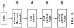
- FIG 18 shows another example.
- a therapy apparatus is inserted 940 and electrodes thereof may be advanced and/or manipulated into a desired use configuration 942.
- a fluid is then infused, as indicated at 944.
- the fluid may be provided to enhance, augment, limit or otherwise affect the subsequent therapy steps.
- a first output, which may be electrical as indicated at 946 is delivered, and a second output, which may also be electrical as indicated at 948, is then delivered.
- the therapy outputs if electrical, may be IRE, thermal, or a combination thereof.
- the therapy outputs are different from one another in one or more respects such as by having one adapted to predominantly thermal effects, while the other is tailored to predominantly IRE effects.
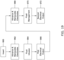
- FIG 19 shows a still further example.
- a therapy apparatus is inserted at 960, and electrodes thereof may be advanced and/or manipulated into a desired use configuration as noted at 962. Fluid infusion may follow at 964, followed by a first therapy which may be electrical as indicated at 966. The electrodes may again be advanced and/or manipulated, as indicated at 968. Steps 962 and 968 may include, for example, advancing, retracting, selecting, deselecting, and/or changing the exposed surface are of one or more electrodes. Fluid management is performed at 970 by, for example, infusing or extracting fluid, if desired.
- extraction of the saline may raise impedance for purposes of delivering a second electrical output 972, thereby reducing heating associated with the second output 972.
- Fluid may be extracted at 970 for purposes of determining whether therapy has been effective at block 968, as the extracellular fluid constituents may indicate whether cells have been destroyed or otherwise affected, for example.
- Figure 20 shows another example.
- a therapy apparatus is inserted at 980 and electrodes thereof may be advanced and/or manipulated into a desired use configuration as noted at 982. Fluid is then infused as noted at 984, and a first set of electrical outputs is delivered. For example, outputs to generate thermal effects may be delivered as part of a first set, followed by outputs to generate IRE effects, using different selection of electrodes as desired within the therapy set 986.
- the electrodes are then advanced and/or manipulated as indicated at 988, fluid management 990 is performed (such as injecting or withdrawing fluid), and a second electrical output set is delivered at 992.
- the first and second electrical output sets comprise each of thermal and IRE outputs, such that the possibility of tract seeding is eliminated in block 986 prior to moving or manipulating electrodes in block 988, as well as before ending the therapy method at block 992.
- Figures 16-20 are illustrative of a number of combinations that may be possible with a versatile apparatus as disclosed herein having the ability to manipulate shaft electrode size and location during the procedure and, if desired, between therapy delivery steps.
- the skilled artisan will appreciate additional variations and adaptations that may be readily achieved with this novel apparatus.
- Method examples described herein can be machine or computer-implemented at least in part. Some examples can include a computer-readable medium or machine-readable medium encoded with instructions operable to configure an electronic device to perform methods as described in the above examples.
- An implementation of such methods can include code, such as microcode, assembly language code, a higher-level language code, or the like. Such code can include computer readable instructions for performing various methods. The code may form portions of computer program products. Further, in an example, the code can be tangibly stored on one or more volatile, non-transitory, or non-volatile tangible computer-readable media, such as during execution or at other times. Examples of these tangible computer-readable media can include, but are not limited to, hard disks, removable magnetic or optical disks, magnetic cassettes, memory cards or sticks, random access memories (RAMs), read only memories (ROMs), and the like.
Landscapes
- Health & Medical Sciences (AREA)
- Life Sciences & Earth Sciences (AREA)
- Engineering & Computer Science (AREA)
- Surgery (AREA)
- Animal Behavior & Ethology (AREA)
- General Health & Medical Sciences (AREA)
- Veterinary Medicine (AREA)
- Public Health (AREA)
- Biomedical Technology (AREA)
- Heart & Thoracic Surgery (AREA)
- Nuclear Medicine, Radiotherapy & Molecular Imaging (AREA)
- Medical Informatics (AREA)
- Molecular Biology (AREA)
- Physics & Mathematics (AREA)
- Otolaryngology (AREA)
- Plasma & Fusion (AREA)
- Biophysics (AREA)
- Radiology & Medical Imaging (AREA)
- Vascular Medicine (AREA)
- Anesthesiology (AREA)
- Hematology (AREA)
- Surgical Instruments (AREA)
- Electrotherapy Devices (AREA)
- Media Introduction/Drainage Providing Device (AREA)
Description
- A variety of therapy modalities have been researched and used for destruction of tumors in the body. Cryoablation and thermal ablation use cold and heat, for example, to destroy tissue. Thermal ablation can be effective and very useful, but has proven difficult to control, particularly in spatial terms. Thermal ablation is not particularly selective in terms of which tissue it will destroy, hampering post-therapy recovery as useful tissue structure such as vasculature is destroyed along with targeted tissue.
- Electroporation has been used in various forms to treat targeted tissue. Electroporation operates by applying electrical pulses that cause cell membranes to alter, creating pores. Above a first threshold electrical field, the cell membranes begin to form pores. Above a second, higher threshold field, those pores can become irreversible, leading to cell death. Thus there are two forms of electroporation, reversible electroporation and irreversible electroporation (IRE). Reversible electroporation can be used in conjunction with the infusion of drugs or other agents which pass through reversibly created pores, where the infused drug/agent then causes selective cell death, however, such added agents can have systemic side effects on the patient.
- New and alternative devices and methods of applying therapy are desired which can combine the beneficial uses of IRE and thermal ablation, as well as reversible electroporation.
-
US 2011/238057 A1 relates to an energy delivery probe and method of treatment using an energy delivery probe.US 5 863 290 A relates to an RF treatment and ablation apparatus that includes a primary antenna inserted into or adjacent to a selected body mass, such as a tumor, with one or more side deployed secondary antennas that are electromagnetically coupled to the primary antenna.US 2005/267467 A1 discloses a conforming electrode catheter comprising a brush electrode having a plurality of flexible filaments or bristles for applying therapeutic energy to target tissue for the formation of spot or continuous linear lesions, cauterization, and desiccation.US 2012/053403 A1 relates to an ablation overtube, which includes a body having a proximal portion, a distal portion and a lumen extending at least partially therethrough. - The present inventors have recognized, among other things, that a problem to be solved is a need for new devices that provide greater physician control over the shaping and use of electrical pulses for IRE and thermal ablation. In some examples, the present invention provides devices that allow a physician to manipulate the exposed electrode surfaces on a tissue destruction apparatus. The present inventors have also recognized that it may be desirable for a physician to be able to combine IRE and one or more additional therapies such as thermal ablation and/or ablation through (or augmented by) the injection of fluids containing drugs, biologics, or other substances.
- A first illustrative, non-limiting example takes the form of a system for destruction of tissue comprising a cannula having a proximal end and a distal end and containing a plurality of tissue penetrating elongate electrodes therein, the electrodes being extendible beyond the distal end of the cannula; a shaft electrode disposed at a spacing from the distal end of the cannula, wherein the spacing distance is adjustable; electrical connectors including at least one electrical connector electrically coupled to at least one of the elongate electrodes, and at least one electrical connector electrically coupled to the shaft electrode; and a sheath movable relative to the shaft electrode and adapted to control exposure of the shaft electrode to patient tissue.
- Additionally or alternatively, the shaft electrode has a length, and the sheath may be moveable to control how much of the length of the shaft electrode is exposed.
- Additionally or alternatively, the shaft electrode extends radially about a portion of the cannula, and the sheath may be moveable to control radial exposure of the shaft electrode.
- Additionally or alternatively, the cannula may include a fluid delivery lumen and a distal portion of the cannula may comprise one or more apertures for fluid infusion. In some examples, the one or more apertures for fluid infusion are located on a first side of the cannula, and the shaft electrode is located on a second side of the cannula, such that the apertures and shaft electrode occupy opposing sides of the cannula within a single axial region of the cannula.
- Additionally or alternatively, at least one of the tissue penetrating elongate electrodes may comprise a fluid delivery lumen therethrough.
- Additionally or alternatively, at least one of the tissue penetrating elongate electrodes may comprise a dielectric coating on a first side of a portion thereof.
- Additionally or alternatively, the shaft electrode may be cylindrical and extend the entire way around the cannula.
- Additionally or alternatively, wherein the shaft electrode may extend about only a portion of the cannula.
- Additionally or alternatively, the plurality of tissue penetrating electrodes may include at least a first tissue penetrating electrode having a first electrical connection and a second tissue penetrating electrode having a second electrical connection, wherein the first and second electrical connections are separately addressable.
- Additionally or alternatively, the sheath may be adapted to cover a radial portion of the shaft electrode to facilitate directional control of an output electrical field between a selected one or more of the first and second tissue penetrating electrodes and a portion of the shaft electrode.
- Additionally or alternatively, the plurality of tissue penetrating electrodes may include at least a first tissue penetrating electrode having a first mechanical coupling and a second tissue penetrating electrode having a second mechanical coupling, wherein the first and second mechanical couplings are separately actuatable to allow the first and second tissue penetrating electrodes to be advanced independent of one another.
- A second illustrative, non-limiting example takes the form of a system for destruction of tissue comprising: a cannula having a proximal end and a distal end and containing a plurality of tissue penetrating elongate electrodes therein, the electrodes being extendible beyond the distal end of the cannula; a shaft electrode disposed near die distal end of the cannula; and a plurality of electrical connectors including at least one electrical connector electrically coupled to at least one of the elongate electrodes, and at least one electrical connector electrically coupled to the shaft electrode; wherein the shaft electrode is disposed at a spacing distance from the distal end of the cannula, wherein the spacing distance is adjustable.
- Additionally or alternatively, the plurality of tissue penetrating electrodes may include at least a first tissue penetrating electrode having a first mechanical coupling and a second tissue penetrating electrode having a second mechanical coupling, wherein the first and second mechanical couplings are separately actuatable to allow the first and second tissue penetrating electrodes to be advanced independent of one another.
- A third illustrative, non-limiting example takes the form of a method of ablating a tissue region using a cannula having a shaft with proximal and distal ends, and one or more tissue penetrating electrodes passing through the shaft and moveable relative to the shaft, the method comprising: inserting the cannula to place the distal end of the shaft at a desired location near a target tissue; advancing at least one of the one or more tissue penetrating electrodes beyond the distal end of the shaft to pierce tissue; delivering a first waveform adapted to cause thermal ablation in a first region relatively nearer to the at least one tissue penetrating electrode; delivering a second waveform adapted to cause irreversible electroporation in a second region relatively more distant from the at least one tissue penetrating electrode.
- Additionally or alternatively to the third illustrative, non-limiting example, the shaft may have a shaft electrode thereon and the cannula comprises a sheath adapted to be moveable relative to the shaft to cover or uncover all or portions of the shaft electrode, and the method further comprises manipulating the sheath to expose a first area of the shaft electrode while the first waveform is delivered, and manipulating the sheath to expose a second area of the shaft electrode while the second waveform is delivered, wherein the first and second areas are different from one another, further wherein each of the first and second waveforms are delivered using at least one of the at least one tissue penetrating electrodes and the shaft electrode as opposing poles for an electrical output.
- Additionally or alternatively to the third illustrative, non-limiting example, the shaft may comprise a fluid infusion lumen having an opening near the distal end thereof, and the method further comprises infusing a fluid through the fluid infusion lumen prior to delivering the first waveform, the fluid adapted to dampen a thermal effect of the first waveform for a first volume of tissue.
- Additionally or alternatively to the third illustrative, non-limiting example, the shaft may comprise a fluid infusion lumen having an opening near die distal end thereof, and the method further comprises infusing a fluid through the fluid infusion lumen prior to delivering the first waveform, the fluid adapted to enhance a thermal effect of the first waveform for a first volume of tissue.
- Additionally or alternatively to the third illustrative, non-limiting example, the shaft may comprise a fluid infusion lumen having an opening near the distal end thereof, and the method further comprises infusing a fluid through the fluid infusion lumen prior to delivering the second waveform, the fluid adapted to enhance the electrical effect of the second waveform.
- Additionally or alternatively to the third illustrative, non-limiting example, the step of delivering the first waveform may be performed prior to delivering the second waveform.
- Additionally or alternatively to the third illustrative, non-limiting example, the step of delivering the first waveform may be performed after delivering the second waveform.
- Additionally or alternatively to the third illustrative, non-limiting example, the first and second waveforms may be each delivered repeatedly by alternating between the first and second waveforms.
- Additionally or alternatively to the third illustrative, non-limiting example, the first waveform may be delivered using a first of the at least one tissue penetrating electrodes, and the second waveform may be delivered using a second of the at least one tissue penetrating electrodes.
- Additionally or alternatively to the third illustrative, non-limiting example, the first waveform may be delivered repeatedly in a first therapy set, and the second waveform may be delivered repeatedly in a second waveform set.
- Additionally or alternatively to the third illustrative, non-limiting example, the method may further comprise repositioning the electrodes after the first therapy set and before the second therapy set.
- Additionally or alternatively to the third illustrative, non-limiting example, at least the second waveform may induce each of reversible and irreversible electroporation, and the method comprises infusing a fluid adapted to cause cell death to a region affected by the reversible electroporation.
- Additionally or alternatively to the third illustrative, non-limiting example, the shaft may have a shaft electrode thereon and the cannula may comprise a sheath adapted to be moveable relative to the shaft to cover or uncover all or portions of the shaft electrode, wherein the method further comprises applying a grounding pad to the patient, wherein the first waveform is delivered using the grounding pad and at least one of the at least one tissue penetrating electrodes as the electrodes for therapy delivery, and the second waveform is delivered using the shaft electrode and at least one of the at least one tissue penetrating electrodes.
- Additionally or alternatively to the third illustrative, non-limiting example, the method may further comprise manipulating the sheath relative to the shaft electrode to expose or cover the shaft electrode between delivery of the first and second waveforms.
- Additionally or alternatively to the third illustrative, non-limiting example, the shaft may have a shaft electrode thereon and the cannula may comprise a sheath adapted to be moveable relative to the shaft to cover or uncover all or portions of the shaft electrode, and the method further comprises applying a grounding pad to the patient, wherein the first waveform is delivered using the shaft electrode and at least one of the at least one tissue penetrating electrodes, and the second waveform is delivered using the grounding pad and at least one of the at least one tissue penetrating electrodes as the electrodes for therapy delivery.
- Additionally or alternatively to the third illustrative, non-limiting example, the method may further comprise manipulating the sheath relative to the shaft electrode to expose or cover the shaft electrode between delivery of the first and second waveforms.
- A fourth illustrative, non-limiting example takes the form of a method of ablating a tissue region using a cannula having a shaft with proximal and distal ends, and one or more tissue penetrating electrodes passing through the shaft and moveable relative to the shaft, the method comprising: inserting the cannula to place the distal end of the shaft at a desired location near a target tissue; advancing at least one of the one or more tissue penetrating electrodes beyond the distal end of the shaft to pierce tissue; and delivering a waveform adapted to cause thermal ablation in a first region relatively nearer to the at least one tissue penetrating electrode and irreversible electroporation in a second region relatively more distant from the at least one tissue penetrating electrode.
- Additionally or alternatively to the fourth illustrative, non-limiting example, the step of delivering a waveform induces reversible electroporation in a third region and the method may further comprise infusing a fluid adapted to cause cell death to a region affected by the reversible electroporation.
- Each of these non-limiting examples can stand on its own, or can be combined in various permutations or combinations with one or more of the other examples.
- This overview is intended to provide an introduction to the subject matter of the present patent application. It is not intended to provide an exclusive or exhaustive explanation of the invention. The detailed description is included to provide further information about the present patent application.
- In the drawings, which are not necessarily drawn to scale, like numerals may describe similar components in different views. Like numerals having different letter suffixes may represent different instances of similar components. The drawings illustrate generally, by way of example, but not by way of limitation, various embodiments discussed in the present document.
-
Figure 1 shows an approximation of different therapy modalities associated with a combination of electrical field strength and pulse duration; -
Figure 2 shows a prior art "Leveen" needle; -
Figures 3-7 show illustrative example therapy apparatuses; -
Figures 8-11 show an illustrative therapy apparatus with manipulation of an electrode; -
Figures 12-13 show illustrative effects of different therapy modes with different electrode configurations; -
Figures 14A-B show a tumor being treated by an illustrative device; -
Figure 15 is a block flow diagram illustrating various examples, and -
Figures 16-20 show a number of therapy sequences. -
Figure 1 shows an approximation of different biophysical responses dependent on the amplitude-time relationship of delivered electrical pulses. The thresholds between cellular responses (10, 20, 30) operate generally as a function of the applied field strength and pulse duration. Below afirst threshold 10, no effect occurs; between thefirst threshold 10 and asecond threshold 20, reversible electroporation occurs. Above thesecond threshold 20, and below athird threshold 30, primarily irreversible electroporation (IRE) occurs. Above athird threshold 30, the effects begin to be primarily thermal. Thus, for example, at a given field strength and duration there may be no effect (location 12), and extending the duration of the field application can yield reversible electroporation (location 22), irreversible electroporation (location 32), and thermal ablation (location 40). - As described in
US Patent 6,010,613 , a transmembrane potential in the range of about one volt is needed to cause reversible electroporation, however the relationship between pulse parameters such as timing and duration and the transmembrane potential required for reversible electroporation remains an actively investigated subject. The required field may vary depending on characteristics of the cells to be treated. At a macro level reversible electroporation requires a voltage in the level of hundreds of volts per centimeter, with irreversible electroporation requiring a still higher voltage. As an example, when considering in vivo electroporation of liver tissue, the reversible electroporation threshold field strength may be about 360 V/cm, and the irreversible electroporation threshold field strength may be about 680 V/cm, as described inUS Patent 8,048,067 . Generally speaking, a plurality of individual pulses are delivered to obtain such effects across the majority of treated tissue; for example, 2, 4, 8, 16, or more pulses may be delivered. - The field for electroporation has typically been applied by delivering a series of individual pulses each having a duration in the range of tens to hundreds of microseconds. For example,
US Patent 8,048,067 describes a series of eight 100 microsecond pulses delivered at 1 second intervals. The '067 patent describes analysis and experiments performed to illustrate that the area betweenlines Figure 1 actually exists, and that a non-thermal IRE method can be achieved. - The tissue membrane does not return instantaneously, from a porated state. As a result, the application of pulses close together in time can have a cumulative effect as described, for example, in
US Patent 8,926,606 . In addition, a series of pulses can be used to first porate a cell membrane and then move large molecules through generated, reversible pores, as described inUS PG Patent App. Pub No. 2007/0025919 . -
While US Patent 8,048,067 discusses performing IRE without thermal effects, andUS Patent 8,926,606 discusses achieving IRE without delivering pulses that exceedline 20 ofFigure 1 and using cumulative effects of closely spaced pulses, die present invention in some examples is directed at the use of multiple regions ofFigure 1 . For example, a single device using either one output circuit having programmable or reconfigurable features, or a single device having a plurality of output circuits tuned to different regions (in terms of voltage, pulse width, or other parameters), may be used to purposefully deliver both thermal and non-thermal ablation therapies. Tuning and tailoring the outputs, including the use of different electrode combinations and therapy parameters, may allow thermal ablation in one spatial region and IRE or other ablation in a second spatial region. Thus, some examples are directed to new and distinct devices that can be manipulated and optimized for delivering therapy within any of the regions shown inFigure 1 . Still further examples combine these concepts to provide a device suited to delivering multiple and distinct therapies such as by achieving IRE pulses in one therapy regimen with a first device configuration, and achieving thermal effects in another therapy regimen using a second device configuration. Additional combinations and details are discussed below. -
Figure 2 shows a prior art "Leveen" needle. As described inUS Patent 5,855,576 , the device comprises aninsertable portion 100 having ashaft 104 that extends to a plurality oftissue piercing electrodes 102 that can be extended or retracted once a target tissue 112 of apatient 110 is accessed. The proximal end of the apparatus is coupled by anelectrical connection 106 to apower supply 108, which can be used to supply RF energy. Typically the Leveen needle would be used to deliver thermal ablation to the target tissue. As described in the `576 patent, a return electrode in the form of a plate or plates may be provided on the patient's skin, a return electrode could be provided as another tissue piercing electrode, or a return electrode may be provided on theshaft 104 near its distal end, proximal of thetissue piercing electrodes 102. Enhancements on the original design can be found, for example, inUS Patent 6,638,277 , which discusses independent actuation of thetissue piercing electrodes 102, both in terms of movement of the electrodes as well as separately electrically activating individual ones of the electrodes. -
Figures 3-7 show illustrative example therapy apparatuses. Referring now toFigure 3 , adevice 200 is shown having amain shaft portion 210, with amoveable insulative sheath 220 coaxially disposed therein. Thesheath 220 partly surrounds aninner shaft 230 that carries areturn electrode 232, which may be referred to herein also as ashaft electrode 232. The inner shaft surrounds aneedle carrier 240 that has thetissue piercing electrodes 242 contained therein. Thetissue piercing electrodes 242 are extendible beyond the distal end of thedevice 200, and particularly beyond the distal end of theinner shaft 230. Aside from theelectrodes - In use, the position of the
return electrode 232 can be adjusted relative to thedistal tip 244 of theneedle carrier 240 as indicated at 234, so as to affect the resulting electric field distribution and corresponding tissue response. In some examples, thedistal tip 244 of theneedle carrier 240 may be pointed or sharpened to allow it to pierce into the targeted tissue prior to advancement of thetissue piercing electrodes 242. Thesheath 220 can be manipulated to advance or retract it relative to thereturn electrode 232. In this example, therefore, thereturn electrode 232 can be covered by thesheath 220 and thereby insulated from tissue to allow use in a unipolar mode, or may be partly covered by thesheath 220 to limit the exposed surface area of thereturn electrode 232. In addition, the distance between the return electrode and thedistal end 244 of theneedle carrier 240 may be manipulated as well. -
Figure 4 shows another example. Here the device orcannula 250 includes amoveable sheath 260 that can be advanced or retracted as indicated at 262, as well astissue piercing electrodes 280 which are again configured to be advanced and/or retracted beyond the distal end of the device orcannula 250 and in particular the needle carrier orinner shaft 270. The needle carrier orinner shaft 270 has a return electrode 272 (which may also be referred to as a shaft electrode) thereon on one side, and one or more fluid infusion apertures as shown at 274. Thefluid infusion apertures 274 may be as shown, at about the same longitudinal location on theinner shaft 270 as theshaft electrode 272, or may be distal and/or proximal thereto, if desired. One or more lumens within theinner shaft 270 can be used to deliver fluid to the fluid infusion apertures 2 74. Theshaft electrode 272 can be placed on one side of the device for use in generally single sided lesion formation, which is commonly used for example in prostate treatments where the therapy catheter is introduced next to, rather than into, the target tissue. If desired, one or more of thetissue piercing electrodes 280 may include a fluid lumen therein to allow delivery of a fluid through thetissue piercing electrodes 280. For example the tissue piercing electrodes may the take form of a hypotube. - The fluid infusion apertures may be used to deliver a fluid that enhances the electrical conductivity of the surrounding tissue in some examples. In other examples, a fluid may be infused that contains a drug, macromolecules, biologic, or other substance which will affect cell properties in one or more ways. For example, macromolecules that disrupt cellular function may be injected, with the intent being to have cells uptake the macromolecules while porated to lead to cell death. In another example, a cationic polymer may be injected, which may increase the susceptibility of the cellular membrane to poration, as described in
US Provisional Patent Application Serial No. 62/585,849 - In some examples, a fluid infusion may comprise saline, or may include dextrose, each of which will affect the conductivity of the surrounding tissue. For example, saline enhances conductivity and dextrose reduces conductivity. In another example, a fluid may be infused that will limit the scope of therapeutic effect of a thermal or IRE therapy by, for example, cooling an area of tissue or limiting current flow or electrical field propagation. For example, biocompatible mineral oil may be used, as it would limit electrical propagation by having non-conductive properties. A glycol mixture at a low concentration may be used to provide a combination of cooling and electrical resistance. In still another alternative, distilled water may be infused, reducing ion concentration, or a reverse osmosis or ion-exchange may be used. For example, a therapy apparatus may have a membrane facilitating reverse osmosis or ion exchange therethrough, reducing ion concentration and thereby increasing localized resistance. A cooling apparatus may be included, such as fluid pumping system, vaporizer or other apparatus, such as in
US Patents 6,428,534 and7,850,681 , as cooling reduces ion mobility. At least with fluid infusion examples, the delivery of such fluids can affect the ratio of extracellular to intracellular conductivity and thereby change the local electric field across a plasma membrane. -
Figure 5 shows another illustrative therapy apparatus. Here, the device orcannula 300 has amoveable sheath 310 therein having a window as indicated at 312. Thesheath 310 in this example can be moved longitudinally 314 as well as rotated 316 over theinner shaft 320 havingelectrodes electrodes Tissue penetrating electrodes Figure 5 may allow various combinations of electrodes for therapy delivery such as: - Between
electrodes - Between
electrode 322 and either ofelectrodes - Between
electrode 324 and either ofelectrodes - Between
electrodes - Between
electrodes 322/324 held electrically in common andelectrodes 326/328 also electrically in common - Using only a portion of
electrode electrodes sheath 312, and one, the other, or both ofelectrodes - Turning now to
Figure 6 , another illustrative therapy apparatus is shown. Here, the device orcannula 350 has asheath 360 that may be manipulated relative to theinner shaft 370. Theinner shaft 370 carries a shaft electrode at 372 and hasfluid infusion apertures 374 that can be used to injectfluid 376. In this example, the tissue piercing electrode array 380 (which may be advanced or retracted individually or as a group, and which may be electrically addressed individually or in pairs, groups, subgroups or as an entire array) is further tailored to allow manipulation of electrode surface area. For example,tissue piercing electrode 382 has aretractable insulative sheath 384 thereon, as doeselectrode 392. One of the tissue piercing electrodes has a sheath extending over its entire length as indicated at 388, with thesheath 388 retractable as indicated at 386. Another of the tissue piercing electrodes is itself retracted as shown at 390. The ability to separately address and control the exposed surface area of at least some of the tissue piercing electrodes facilitates greater physician control. Now, for example, individual addressing allows separate field definition as indicated at 394 and 396, allowing greater targeting of the therapy field. In an example, the targeted andindividualized fields -
Figure 7 shows an illustrative system. Thesystem 400 includes atherapy device 410 having a relatively complex handle structure includingindividual actuators 410 for manipulating the tissue piercing electrodes (individually, as groups, or as the entire array) at the distal tip of the apparatus, and aseparate actuator 414 for controlling a sheath that selectively limits the exposed surface area of the return electrode.Electrical cord 416 couples to asignal generator 418, while afluid coupling 420 is linked to afluid source 422. The distal portion of thetherapy device 410 is shown at 430 and may incorporate any of the designs inFigures 3-6 , above, orFigures 8-11 , below. -
Figures 8-11 show an illustrative therapy apparatus with manipulation of an electrode. Asheath 450 is shown having a window at 452. The sheath may be, for example, a 0.13 mm (0.005 inch polyimide tube, though any design or material may be used instead of polyimide of such thickness; other insulative polymers may be used, for example. Theinner shaft 460 carriesshaft electrode 462. The shaft electrode may be, for example, a titanium or medical grade stainless steel element, and may be a ring electrode or a directional electrode as shown in examples above. Aconductor 464, such as a stainless steel conductor, can be provided throughshaft 460 which may be, for example, a multi-lumen tube of any suitable material such as polyimide, polyether block amide, or other suitable material. In one configuration, as shown inFigure 9 , thesheath 450 may completely cover theelectrode 462 by having thewindow 452 proximal of theelectrode 462. Advancing thesheath 450 as shown inFigure 10 allows a selected and reduced area of theelectrode 462 to be exposed throughwindow 452. Retracting thesheath 450 as shown inFigure 11 allows theentire electrode 462 to be exposed. -
Figures 12-13 show illustrative effects of different therapy modes with different electrode configurations.Figure 12 shows variation in IRE field strength with variation of shaft electrode length, using a homogenous medium model. A first example at 500 applies a 3000 volt output between a 2.5mm shaft electrode 502 andtissue piercing electrodes 504, with the boundaries of the IRE field shown at 506. To ensure reliable IRE in thefield boundary 506, in application, the output may be delivered for example as a series of 4 to 20 pulses (or more) with durations in the 0.1 to 100 microsecond range (or more) at a frequency of 1 to 100 Hz (or more or less), for example, 8 to 10 pulses of 5 microsecond duration at 10 Hz may be delivered. Using the same output voltage, a second example at 520 assumes a 5 mmshaft electrode length 522. TheIRE field boundary 526 closely envelopes the tissue piercing electrodes and can be seen to have widened and lengthened about theshaft electrode 522. Extending theshaft electrode 542 length to 10 mm, as shown at 540, again elongates the boundaries of theIRE field boundary 546; it can be seen also that the field span surrounding thetissue piercing electrodes 544 becomes larger as well. Again extending theshaft electrode 562 length to 15 mm changes the shape of theIRE field boundary 566, adding still further to the margin around thetissue piercing electrodes 564, but achieving a field that narrows near the proximal end of theshaft electrode 562, as seen at 568. -
Figure 13 shows thermal ablation boundaries using a monopolar configuration. Here, a return plate electrode (not shown) is placed on the skin of the patient, typically using a hydrogel or the like to reduce tissue/electrode impedance, as the therapy device is used to deliver output therapy. As shown at 600, at a relatively lower voltage (such as 2000 volts) thethermal ablation boundaries 604 are generally limited to the region of the tissue piercing electrodes. With increased voltage, as shown at 620 and 640, the thermal ablation region expands quickly to develop a volume around thetissue penetrating electrodes - The ability to manipulate the shape and volume of treatment effectiveness can be used in a variety of ways. In some examples, the shaft electrode size may be varied while a plurality of IRE treatments take place, wherein the individual IRE treatments comprise a plurality of applied pulses delivered as a set of therapy pulses, and wherein the shaft electrode size and usage is changed from one set to the next as by, for example, exposing more or less of the shaft electrode from one set to the next, or by switching from a monopolar to bipolar treatment mode by enabling or disabling the shaft electrode. For example, thermal ablation modalities can be difficult to control due to heat sink effects of blood flow in nearby vasculature and/or the treatment device itself. In the prior art, tract seeding can be prevented by applying ablation therapy during retraction of the device to cause a thin layer of tissue necrosis along the tract. Application of IRE pulses in sets before or after the thermal treatment may target not only the tissue adjacent to the electrodes themselves, but also tissue that is located outside of the thermal treatment region between two electrodes.
- In some examples, IRE and thermal treatments are combined into one overall therapy regimen as by, for example, alternating between pulses of longer duration (which generate thermal effects) and shorter duration (which generate IRE-type effects) within a therapy pulse set. In another example, an IRE output is generated after a thermal output and before adjustment of electrode position to target a different area of the anatomy; for example, a sequence of thermal output and IRE output may be followed by extending or retracting an electrode or insulator over an electrode, with the thermal output used to create larger volume effects and the IRE output used to eliminate possible tract seeding.
- In another example, IRE is used before thermal output. IRE can reduce impedance in affected tissue. By first reducing impedance, the thermal output of a subsequent stage can generate a greater quantity of thermal affect with reduced voltage output, as the lowered impedance allows higher current at a given voltage, where it is recognized that the square of the current yields the heating effect of a given therapy.
-
Figures 14A-B shows a tumor being treated by an illustrative device. InFigure 14A , a therapy device orcannula 700 has been inserted into a patient's tissue. A shaft electrode is shown at 702, with amoveable sheath 708 on the shaft as well to adjust the area of theelectrode 702 that is exposed to patient tissue. - A
distal tip 704 of thecannula 700 has an angled or pointed end to allow passage through the patient tissue. In some examples thedistal tip 704 is relatively sharp to allow it to pierce through tissue; such an example is shown inFigure 14A where thedistal tip 704 has been used to pierce atumor 720 and surroundinglesion 722. In other examples thedistal tip 704 may be blunted to allow atraumatic passage through a body lumen such as a biliary duct, lymph vessel or duct, urethra, mammary duct, digestive passageway, blood vessel, or other body passageway, as the case may be. Thedistal tip 704 may be partly blunted to allow its use to separate body tissue layers as it passes, for example, alongside the outer capsule of a body organ such as the liver or kidney. - A plurality of tissue piercing electrodes or needle electrodes are shown at 706. As can be seen, the cannula is inserted 700 far enough into the tumor to place the shaft electrode at least partly in the tumor, and the needle electrodes extend beyond the tumor and lesion. Tract seeding in this example may occur if abnormal cells from the
tumor 720 stick to theneedle electrodes 706 as they pass out through the lesion and into surrounding normal tissue, as well as by cells sticking to the main body of thecannula 700 such assheath 708 andshaft electrode 702 during removal or repositioning maneuvers. In either event, the abnormal cells may be transported out of the tumor into surrounding tissue, and so an ablation or cell destruction therapy that destroys such cells in addition to die cells of thetumor 720 and surroundinglesion 722 is desirable. - In an example, a plurality of distinct treatment steps take place using differing parameters and electrodes to account for both the extent of the
tumor 720 and any potential tract seeding. For example,currents 730 may be generated in a bipolar treatment stage or stages between one or more of the tissue piercing orneedle electrodes 706 and theshaft electrode 702.Currents 732 may also be generated in one or more monopolar treatment stages between anexternal return electrode 740 and one or more ofdie needle electrodes 706.Currents 734 may be generated in one or more monopolar stages using theshaft electrode 702 and theexternal return electrode 740. Theexternal return electrode 740 may be, for example, a grounding pad. The grounding pad orexternal return electrode 740 may be placed in different positions for different steps, to direct the electrical field in different directions, if desired. -
Figure 14B illustrates results of several therapy steps using distinct therapy modalities. For example, a first lesion field is generated at 770 by the use of a monopolar thermal or IRE therapy delivery using theneedle electrodes 706 and anexternal return electrode 740. A second lesion field is generated at 772 by the use of a bipolar IRE or thermal therapy using most or all of theshaft electrode 702 as one pole and one or more of theneedle electrodes 706 as opposing pole(s). A third lesion field is generated at 774 using a monopolar IRE or thermal therapy delivered using a portion of the shaft electrode 702 (for example, a lesser extent of theshaft electrode 702 may be exposed during such delivery than is shown inFigure 14B ) and anexternal return electrode 740. Depending on the size and shape of thetumor 720, only two such fields may be generated in some examples. - The present invention encompasses each combination of the two monopolar and bipolar therapy modes, in either IRE or thermal formats, in any desired order. The skilled person can readily generate the complete matrix. For purposes of illustration, however, following are some approaches that may be used in some specific examples:
First Step % Type Second Step % Type Third Step / Type 772 / IRE 770 / Thermal (none) 770 / Thermal 772 / IRE (none) 772 / IRE 770 / Thermal 774 / Thermal - In some examples a monopolar therapy mode is used for thermal ablation using a lower voltage gradient, and a bipolar therapy mode is used for IRE using a higher voltage gradient. For example, two electrodes 2.5 cm apart can use a 2000 volt output to exceed 650 V/cm field for IRE, while two
electrodes 10 cm apart using 1000 volt output will yield a 100 V/cm field, which is sufficient to attain thermal effects if using longer pulse widths and/or a higher duty cycle, with the combination reducing damage or excitation on distant muscle or nerve fibers of the patient in either case. In this example, the pulse-duration and field strength relationship with thermal damage and irreversible electroporation induction is harnessed to produce a therapeutic effect with desirable damage modes. - As can be seen in
Figure 14B , while none of the individual therapy steps completely encompasses thetumor 720, the combination of modes and therapy steps captures the entire tumor as well as a margin about thetumor 720, while also addressing the possibility of tract seeding. The use of IRE in addition to thermal ablation also addresses tract seeding that could otherwise be facilitated by localized heat sink effects of the apparatus itself. -
Figure 15 is a block flow diagram illustrating various examples. Theoverall method 800 may be subject to a number of repetitions, both internally within the method and as separate steps in a procedure to treat a patient. A therapy device is inserted at 810.Insertion 810 may make use of an existing lumen or channel of the patient (such as using a blood vessel or other duct/vessel in the patient) or may comprise piercing tissue with an instrument designed for such piercing. Once inserted to a location that is desirable, the treatment apparatus may deploy one or more electrodes, as indicated at 820. In some example, tissue piercing electrodes, such as in the modified Leveen-style devices shown above, may be extended out of internal lumens of the therapy device to pierce tissue or otherwise position electrodes for use. A therapy is then delivered, as indicated at 830. The therapy may be, for example, anIRE therapy 832 in which monophasic or biphasic (or triphasic or other multiphasic) electrical output is generated with relatively high amplitudes (yielding fields of over 600 V/cm, for example) and short pulsewidths (for example in the range of 0.1 to 100 microseconds) at a relatively lower duty cycle (such as 1 to 100 Hz - such as a duty cycle of less than 0.1%), which may avoid thermal heating to yield predominantly IRE therapy. The therapy may include injection of a fluid to enhance or modify effectiveness or spatial effects of an applied electrical therapy, or may instead be injection of an ablative fluid such as a fluid having limited caustic effects, or cooling or heating effects, as indicated at 834. The therapy may be a thermal treatment, which may incorporate somewhat lower pulse amplitudes (fields of less than 600 V/cm, for example) at longer pulsewidths (for example, 10 microseconds to 100 milliseconds) at a relatively higher duty cycle (such as by application of the pulses at a frequency of 10 Hz to 100 kHz, in some examples to yield a duty cycle of greater than 0.1%). For example, saline may be injected to reduce local tissue impedance, increasing current flow for a given output voltage, such that both an electrical output (832/836) is delivered and the fluid (834). Some examples may use bothIRE 832 andthermal ablation 836 from a single output waveform by increasing pulsewidth and/or the duty cycle of IRE outputs to cause thermal effects. - Within the illustrative example, after a therapy delivery at 830, the system proceeds to make an adjustment as indicated at 840 and then cycles back to the therapy step. For example, an adjustment may include the injection of
fluid 842, selecting, deselecting, moving or modifying the exposed surface area of aneedle electrode 844, adjusting the position or exposed surface area of ashaft electrode 846, or moving, adding or removing a cutaneous orskin electrode 848. In an illustration, a therapy may be delivered at 830 as a monopolarthermal ablation step 836, an adjustment may be made at 840 by exposing ashaft electrode 846 and removing or deselecting askin electrode 848, and then delivering therapy again at 830, this time using a bipolar IRE output with shaft and needle electrodes. - In some examples a set quantity of therapy steps and
adjustments 830/840 may be performed and the method ends by exiting theloop 830/840, proceeding to theend block 860. In other examples, after one ormore therapy steps 830, the method engages anobservation step 850, in which one or more observable features are quantities or checked to determine progress or status of the therapy. For example, block 850 may refer totemperature 852,impedance 854, and/or animaging modality 856 such as a CT image. In some examples,impedance 854 may be checked between any selected pair of electrodes such as between needle electrodes, between a needle electrode and a shaft electrode, between a needle electrode and a surface electrode, or between a probe electrode and an electrode of the therapy apparatus, or between two probe electrodes. It should be understood that as therapy progresses, cell death may occur, releasing intercellular fluid into the extracellular matrix and reducing impedance as cell death occurs, making impedance 854 a useful observation. Also, as therapy progresses,temperature 852 may be checked to ensure that temperatures as measured using, for example a temperature sensor on the therapy apparatus or a temperature sensor on a separate probe, is in a desired range. For example, as cell death occurs, local temperature may increase more greatly as local impedance drops and current flows increase at a given voltage, making temperature a useful measure of status. Animage 856 may be used as well to determine the status of a tumor or lesion. Afterobservation 850, anadjustment 840 may be made if desired ortherapy 830 may resume. Ifobservation 850 shows satisfactory completion of treatment, the method may go to theend block 860 if desired. - In one example, several iterations of
thermal therapy 830/836 may be performed, withobservation 850 used to determine when the thermal therapy is sufficiently completed, and then an additional therapy may be delivered as anIRE therapy 830/832 to limit the possibility of tract seeding. Several additional examples of therapy sequences follow inFigures 16-20 . -
Figure 16 shows one example. A therapy apparatus is inserted to a desired location at 900. Electrodes are advanced and manipulated to desired positions relative to a tumor or other target tissue, such as by establishing a perimeter near or around the target tissue, as indicated at 902. A first electrical output is provided as a first therapy step at 904, such as by delivering IRE, thermal, or an output tailored to generate a combination thereof. A second electrical output is provided as a second therapy step at 906, such as by delivering IRE, thermal, or an output tailored to generate a combination thereof. For example, an IRE therapy may be delivered at 904 and a thermal therapy at 906, or the other way around. - The method of
Figure 16 , as well as any other of the examples herein, may be further combined with additional therapy elements, such as for example, the delivery of a laser ablation (by, for example, inserting a separate optical instrument or including one or more optical fibers in a therapy apparatus similar to those shown above). For example, an optical therapy apparatus may be inserted and used to perform laser-based ablation, with IRE then delivered via electrodes on the laser apparatus to mitigate tract seeding. Ultrasound or other vibrational therapy may be added as well. For example, rather than an electrical therapy as the "thermal" therapy, followed by IRE to deal with tract seeding possibilities, an ultrasound instrument may be provided and used in a first step, with electrodes provided thereon to allow use of IRE to complete the procedure prior to withdrawal of the ultrasound instrument. Thus for each of the ultrasound and laser examples, block 904 may instead be treated as deliver first therapy, where the first therapy is ultrasound or laser therapy, followed by the electrical output at 906. -
Figure 17 shows another example. Again, a therapy apparatus is inserted 920 and electrodes thereof may be advanced and/or manipulated into a desired use configuration. A first output, which may be electrical as indicated at 924, is delivered. The electrodes are then manipulated as indicated at 926 by, for example, selecting, deselecting, moving, or adjusting the exposed surface area thereof. A second output, which may be electrical, is then delivered as indicated at 928. As withFigure 16 , the first or second outputs may be IRE, thermal, or a combination thereof. -
Figure 18 shows another example. Here, a therapy apparatus is inserted 940 and electrodes thereof may be advanced and/or manipulated into a desireduse configuration 942. A fluid is then infused, as indicated at 944. The fluid may be provided to enhance, augment, limit or otherwise affect the subsequent therapy steps. A first output, which may be electrical as indicated at 946 is delivered, and a second output, which may also be electrical as indicated at 948, is then delivered. The therapy outputs, if electrical, may be IRE, thermal, or a combination thereof. In the example, the therapy outputs are different from one another in one or more respects such as by having one adapted to predominantly thermal effects, while the other is tailored to predominantly IRE effects. -
Figure 19 shows a still further example. Here, a therapy apparatus is inserted at 960, and electrodes thereof may be advanced and/or manipulated into a desired use configuration as noted at 962. Fluid infusion may follow at 964, followed by a first therapy which may be electrical as indicated at 966. The electrodes may again be advanced and/or manipulated, as indicated at 968.Steps electrical output 972, thereby reducing heating associated with thesecond output 972. Fluid may be extracted at 970 for purposes of determining whether therapy has been effective atblock 968, as the extracellular fluid constituents may indicate whether cells have been destroyed or otherwise affected, for example. -
Figure 20 shows another example. Here, a therapy apparatus is inserted at 980 and electrodes thereof may be advanced and/or manipulated into a desired use configuration as noted at 982. Fluid is then infused as noted at 984, and a first set of electrical outputs is delivered. For example, outputs to generate thermal effects may be delivered as part of a first set, followed by outputs to generate IRE effects, using different selection of electrodes as desired within thetherapy set 986. The electrodes are then advanced and/or manipulated as indicated at 988,fluid management 990 is performed (such as injecting or withdrawing fluid), and a second electrical output set is delivered at 992. In an example, the first and second electrical output sets comprise each of thermal and IRE outputs, such that the possibility of tract seeding is eliminated inblock 986 prior to moving or manipulating electrodes inblock 988, as well as before ending the therapy method atblock 992. - The examples of
Figures 16-20 are illustrative of a number of combinations that may be possible with a versatile apparatus as disclosed herein having the ability to manipulate shaft electrode size and location during the procedure and, if desired, between therapy delivery steps. The skilled artisan will appreciate additional variations and adaptations that may be readily achieved with this novel apparatus. - The above detailed description includes references to the accompanying drawings, which form a part of the detailed description. The drawings show, by way of illustration, specific embodiments in which the invention can be practiced. These embodiments are also referred to herein as "examples." Such examples can include elements in addition to those shown or described. However, the present inventors also contemplate examples in which only those elements shown or described are provided. Moreover, the present inventors also contemplate examples using any combination or permutation of those elements shown or described (or one or more aspects thereof), either with respect to a particular example (or one or more aspects thereof), or with respect to other examples (or one or more aspects thereof) shown or described herein.
- In this document, the terms "a" or "an" are used, as is common in patent documents, to include one or more than one, independent of any other instances or usages of "at least one" or "one or more." Moreover, in the following claims, the terms "first," "second," and "third," etc. are used merely as labels, and are not intended to impose numerical requirements on their objects.
- Method examples described herein can be machine or computer-implemented at least in part. Some examples can include a computer-readable medium or machine-readable medium encoded with instructions operable to configure an electronic device to perform methods as described in the above examples. An implementation of such methods can include code, such as microcode, assembly language code, a higher-level language code, or the like. Such code can include computer readable instructions for performing various methods. The code may form portions of computer program products. Further, in an example, the code can be tangibly stored on one or more volatile, non-transitory, or non-volatile tangible computer-readable media, such as during execution or at other times. Examples of these tangible computer-readable media can include, but are not limited to, hard disks, removable magnetic or optical disks, magnetic cassettes, memory cards or sticks, random access memories (RAMs), read only memories (ROMs), and the like.
- The above description is intended to be illustrative, and not restrictive. For example, the above-described examples (or one or more aspects thereof) may be used in combination with each other. Other embodiments can be used, such as by one of ordinary skill in the art upon reviewing the above description.
Claims (15)
- A system for destruction of tissue comprising:a cannula (240) having a proximal end and a distal end (244) and containing a plurality of tissue penetrating elongate electrodes (242) therein, the electrodes being extendible beyond the distal end of the cannula;a shaft electrode (232) disposed at a spacing distance from the distal end (244) of the cannula, wherein the spacing distance is adjustable;electrical connectors including at least one electrical connector electrically coupled to at least one of the elongate electrodes, and at least one electrical connector electrically coupled to the shaft electrode; anda sheath (220) movable relative to the shaft electrode (232) and adapted to control exposure of the shaft electrode to patient tissue.
- The system of claim 1, wherein the shaft electrode (232) has a length, and the sheath (220) is moveable to control how much of the length of the shaft electrode is exposed.
- The system of either of claims 1 or 2, wherein the shaft electrode (232) extends radially about a portion of the cannula (240), and the sheath (220) is moveable to control radial exposure of the shaft electrode (232).
- The system of any of claims 1-3, wherein the cannula (270) includes a fluid delivery lumen and a distal portion of the cannula comprises one or more apertures (274) for fluid infusion.
- The system of claim 4, wherein the one or more apertures (274) for fluid infusion are located on a first side of the cannula (270), and the shaft electrode (272) is located on a second side of the cannula, such that the apertures and shaft electrode occupy opposing sides of the cannula within a single axial region of the cannula.
- The system of any of claims 1-5, wherein at least one of the tissue penetrating elongate electrodes (280) comprises a fluid delivery lumen therethrough.
- The system of any of claims 1-6, wherein at least one of the tissue penetrating elongate electrodes (280) comprises a dielectric coating on a first side of a portion thereof.
- The system of any of claims 1-7, wherein the shaft electrode (232) is cylindrical and extends the entire way around the cannula (240).
- The system of any of claims 1-8, wherein the shaft electrode (232) extends about only a portion of the cannula (240).
- The system of any of claims 1-9, wherein the plurality of tissue penetrating electrodes includes at least a first tissue penetrating electrode (326) having a first electrical connection and a second tissue penetrating electrode (328) having a second electrical connection, wherein the first and second electrical connections are separately addressable.
- The system of claim 10, wherein the sheath (450) is adapted to cover a radial portion of the shaft electrode (462) to facilitate directional control of an output electrical field between a selected one or more of the first and second tissue penetrating electrodes and a portion of the shaft electrode.
- The system of any of claims 1-11, wherein the plurality of tissue penetrating electrodes includes at least a first tissue penetrating electrode (326) having a first mechanical coupling and a second tissue penetrating electrode (328) having a second mechanical coupling, wherein the first and second mechanical couplings are separately actuatable to allow the first and second tissue penetrating electrodes to be advanced independent of one another.
- The system of claim 1, wherein the shaft electrode (232) is disposed on an inner shaft (230) surrounding the cannula (240), wherein the spacing distance is adjustable by moving the inner shaft (230).
- The system of claim 10, wherein the sheath (450) includes a window (452) configured to expose a reduced area of the shaft electrode (462).
- The system of claim 1, wherein at least one of the tissue penetrating elongate electrodes (242) has a retractable insulative sheath (384) disposed thereon.
Applications Claiming Priority (2)
| Application Number | Priority Date | Filing Date | Title |
|---|---|---|---|
| US201862620873P | 2018-01-23 | 2018-01-23 | |
| PCT/US2019/014680 WO2019147619A1 (en) | 2018-01-23 | 2019-01-23 | Enhanced needle array and therapies for tumor ablation |
Publications (2)
| Publication Number | Publication Date |
|---|---|
| EP3742998A1 EP3742998A1 (en) | 2020-12-02 |
| EP3742998B1 true EP3742998B1 (en) | 2023-11-15 |
Family
ID=65279836
Family Applications (1)
| Application Number | Title | Priority Date | Filing Date |
|---|---|---|---|
| EP19703626.2A Active EP3742998B1 (en) | 2018-01-23 | 2019-01-23 | Enhanced needle array and therapies for tumor ablation |
Country Status (5)
| Country | Link |
|---|---|
| US (2) | US11364070B2 (en) |
| EP (1) | EP3742998B1 (en) |
| JP (1) | JP7045464B2 (en) |
| CN (1) | CN111615371B (en) |
| WO (1) | WO2019147619A1 (en) |
Families Citing this family (26)
| Publication number | Priority date | Publication date | Assignee | Title |
|---|---|---|---|---|
| JP7287888B2 (en) | 2016-06-27 | 2023-06-06 | ギャラリー,インコーポレイテッド | A generator, a catheter with electrodes, and a method of treating a lung passageway |
| US12403305B2 (en) | 2016-06-27 | 2025-09-02 | Galvanize Therapeutics, Inc. | Immunostimulation in the treatment of viral infection |
| DK4218641T3 (en) | 2017-12-26 | 2025-08-18 | Galvanize Therapeutics Inc | OPTIMIZING ENERGY DELIVERY FOR VARIOUS APPLICATIONS |
| EP3937811B1 (en) | 2019-03-15 | 2024-07-10 | Boston Scientific Scimed, Inc. | Time multiplexed waveform for selective cell ablation |
| EP3937812B1 (en) | 2019-03-15 | 2025-04-23 | Boston Scientific Scimed, Inc. | Waveform generator and control for selective cell ablation |
| JP7551648B2 (en) * | 2019-04-18 | 2024-09-17 | ガルヴァナイズ セラピューティクス,インコーポレイテッド | Apparatus and system for treating abnormal tissue, |
| EP4025145B1 (en) * | 2019-09-04 | 2024-07-03 | Arga' Medtech Sa | Ablation equipment to treat target regions of tissue in organs |
| CN111529049B (en) * | 2019-10-11 | 2025-12-19 | 深圳钮迈科技有限公司 | Double-electrode probe and operation method thereof |
| CN112641506B (en) * | 2019-10-11 | 2025-01-17 | 广州爱锘德医疗器械有限公司 | Slide fastener structure and adjusting device |
| CN114945338A (en) | 2019-10-15 | 2022-08-26 | 波士顿科学国际有限公司 | Control system and user interface for an ablation system |
| JP7591833B2 (en) | 2019-10-21 | 2024-11-29 | インキャンド セラピューティクス プライベート リミテッド | Methods and Apparatus for Phototherapy - Patent application |
| US20210162210A1 (en) * | 2019-12-03 | 2021-06-03 | Biosense Webster (Israel) Ltd. | Using reversible electroporation on cardiac tissue |
| US11660135B2 (en) * | 2019-12-05 | 2023-05-30 | Biosense Webster (Israel) Ltd. | Generating and interleaving of irreversible-electroporation and radiofrequnecy ablation (IRE/RFA) waveforms |
| WO2021119173A1 (en) * | 2019-12-09 | 2021-06-17 | Rhode Island Hospital | Thermal accelerant compositions and methods of use |
| US11992260B2 (en) | 2020-03-31 | 2024-05-28 | Boston Scientific Scimed, Inc. | Smart probe identification for ablation modalities |
| WO2021216515A1 (en) | 2020-04-21 | 2021-10-28 | Boston Scientific Scimed, Inc. | Adaptive ecg triggering in an ablation system |
| US12076071B2 (en) | 2020-08-14 | 2024-09-03 | Kardium Inc. | Systems and methods for treating tissue with pulsed field ablation |
| US12446944B2 (en) | 2021-04-26 | 2025-10-21 | Pulse Biosciences, Inc. | Mapping and ablation applicators |
| AU2022263951B2 (en) | 2021-04-26 | 2024-12-05 | Pulse Biosciences, Inc. | Circumferential ablation devices and methods |
| US12564440B2 (en) | 2021-04-26 | 2026-03-03 | Pulse Biosciences, Inc. | Multi-strut ablation and sensing catheter devices and methods |
| US20220370128A1 (en) * | 2021-05-18 | 2022-11-24 | Biosense Webster (Israel) Ltd. | Efficiency of ire ablation procedure by applying stress signal to target tissue |
| WO2023097113A1 (en) | 2021-11-29 | 2023-06-01 | Boston Scientific Scimed, Inc. | Bipolar needle with adjustable electrode for geometrically controlled thermal ablation of biological tissue |
| JP7788555B2 (en) * | 2021-11-30 | 2025-12-18 | ボストン サイエンティフィック メディカル デバイス リミテッド | System for tissue puncture |
| CN121772888A (en) | 2023-07-05 | 2026-03-31 | 波士顿科学国际有限公司 | Multielectrode devices, systems, and methods for medical surgery |
| FR3154591B1 (en) * | 2023-10-25 | 2025-12-26 | Hopitaux Paris Assist Publique | LOCALIZED TISSUE TREATMENT DEVICE |
| US20260060745A1 (en) * | 2024-08-29 | 2026-03-05 | Boston Scientific Medical Device Limited | Rf guidewire needle with passive electrode sheathing design |
Family Cites Families (64)
| Publication number | Priority date | Publication date | Assignee | Title |
|---|---|---|---|---|
| US5370675A (en) | 1992-08-12 | 1994-12-06 | Vidamed, Inc. | Medical probe device and method |
| EP0398960B1 (en) | 1988-01-21 | 1995-12-06 | Massachusetts Institute Of Technology | Transport of molecules across tissue using electroporation |
| US5683384A (en) * | 1993-11-08 | 1997-11-04 | Zomed | Multiple antenna ablation apparatus |
| US5868740A (en) * | 1995-03-24 | 1999-02-09 | Board Of Regents-Univ Of Nebraska | Method for volumetric tissue ablation |
| US6041252A (en) | 1995-06-07 | 2000-03-21 | Ichor Medical Systems Inc. | Drug delivery system and method |
| US5863290A (en) * | 1995-08-15 | 1999-01-26 | Rita Medical Systems | Multiple antenna ablation apparatus and method |
| US6010613A (en) | 1995-12-08 | 2000-01-04 | Cyto Pulse Sciences, Inc. | Method of treating materials with pulsed electrical fields |
| US5718246A (en) | 1996-01-03 | 1998-02-17 | Preferential, Inc. | Preferential induction of electrically mediated cell death from applied pulses |
| JPH1024049A (en) | 1996-04-04 | 1998-01-27 | Valleylab Inc | Electrosurgical unit |
| US5868735A (en) | 1997-03-06 | 1999-02-09 | Scimed Life Systems, Inc. | Cryoplasty device and method |
| US5873849A (en) | 1997-04-24 | 1999-02-23 | Ichor Medical Systems, Inc. | Electrodes and electrode arrays for generating electroporation inducing electrical fields |
| US6050992A (en) * | 1997-05-19 | 2000-04-18 | Radiotherapeutics Corporation | Apparatus and method for treating tissue with multiple electrodes |
| US6043066A (en) | 1997-09-04 | 2000-03-28 | Mangano; Joseph A. | Cell separation using electric fields |
| US7456012B2 (en) | 1997-11-06 | 2008-11-25 | Cellectricon Ab | Method and apparatus for spatially confined electroporation |
| WO1999035986A1 (en) | 1998-01-14 | 1999-07-22 | Conway-Stuart Medical, Inc. | Electrosurgical apparatus for treating gastroesophageal reflux disease (gerd) and method |
| US6537272B2 (en) * | 1998-07-07 | 2003-03-25 | Medtronic, Inc. | Apparatus and method for creating, maintaining, and controlling a virtual electrode used for the ablation of tissue |
| US6428534B1 (en) | 1999-02-24 | 2002-08-06 | Cryovascular Systems, Inc. | Cryogenic angioplasty catheter |
| WO2000066017A1 (en) | 1999-05-04 | 2000-11-09 | Curon Medical, Inc. | Electrodes for creating lesions in tissue regions at or near a sphincter |
| US6387671B1 (en) | 1999-07-21 | 2002-05-14 | The Regents Of The University Of California | Electrical impedance tomography to control electroporation |
| US6326177B1 (en) | 1999-08-04 | 2001-12-04 | Eastern Virginia Medical School Of The Medical College Of Hampton Roads | Method and apparatus for intracellular electro-manipulation |
| CA2384866C (en) | 1999-09-28 | 2012-07-10 | Stuart D. Edwards | Treatment of tissue by application of energy and drugs |
| IT1320187B1 (en) | 2000-04-21 | 2003-11-26 | Igea Srl | ELECTRO-PORTATION DEVICE AND METHOD THAT PROVIDES A MODULATED SIGNAL UNDER THE CONTINUOUS CONTROL OF THE ELECTRO-PERMEABILIZATION |
| US20010044596A1 (en) | 2000-05-10 | 2001-11-22 | Ali Jaafar | Apparatus and method for treatment of vascular restenosis by electroporation |
| US6638277B2 (en) | 2000-07-06 | 2003-10-28 | Scimed Life Systems, Inc. | Tumor ablation needle with independently activated and independently traversing tines |
| US6962587B2 (en) * | 2000-07-25 | 2005-11-08 | Rita Medical Systems, Inc. | Method for detecting and treating tumors using localized impedance measurement |
| US8251986B2 (en) | 2000-08-17 | 2012-08-28 | Angiodynamics, Inc. | Method of destroying tissue cells by eletroporation |
| US6832111B2 (en) | 2001-07-06 | 2004-12-14 | Hosheng Tu | Device for tumor diagnosis and methods thereof |
| US6994706B2 (en) | 2001-08-13 | 2006-02-07 | Minnesota Medical Physics, Llc | Apparatus and method for treatment of benign prostatic hyperplasia |
| US7245963B2 (en) | 2002-03-07 | 2007-07-17 | Advisys, Inc. | Electrode assembly for constant-current electroporation and use |
| US7756583B2 (en) | 2002-04-08 | 2010-07-13 | Ardian, Inc. | Methods and apparatus for intravascularly-induced neuromodulation |
| AU2003299471A1 (en) | 2002-05-07 | 2004-05-13 | Kai Kroll | Method and device for treating concer with electrical therapy in conjunction with chemotherapeutic agents and radiation therapy |
| DE10233668A1 (en) | 2002-07-24 | 2004-02-19 | Siemens Ag | Data record processing method for a data record for capacity describing a tubular vessel in the body and its surroundings defines a working point for a cutting area |
| US7416549B2 (en) | 2003-10-10 | 2008-08-26 | Boston Scientific Scimed, Inc. | Multi-zone bipolar ablation probe assembly |
| EP1684655A2 (en) | 2003-11-18 | 2006-08-02 | SciMed Life Systems, Inc. | System and method for tissue ablation |
| ES2729378T3 (en) | 2003-12-24 | 2019-11-04 | Univ California | Tissue ablation with irreversible electroporation |
| US20050267467A1 (en) * | 2004-01-16 | 2005-12-01 | Saurav Paul | Bipolar conforming electrode catheter and methods for ablation |
| US8211104B2 (en) | 2005-01-06 | 2012-07-03 | Boston Scientific Scimed, Inc. | Co-access bipolar ablation probe |
| US20080009927A1 (en) * | 2005-01-11 | 2008-01-10 | Vilims Bradley D | Combination Electrical Stimulating and Infusion Medical Device and Method |
| US8114070B2 (en) | 2005-06-24 | 2012-02-14 | Angiodynamics, Inc. | Methods and systems for treating BPH using electroporation |
| US20060293730A1 (en) | 2005-06-24 | 2006-12-28 | Boris Rubinsky | Methods and systems for treating restenosis sites using electroporation |
| US7794458B2 (en) * | 2005-07-22 | 2010-09-14 | Boston Scientific Scimed, Inc. | Bipolar radio frequency ablation device with retractable insulator |
| JP5826450B2 (en) | 2005-07-22 | 2015-12-02 | ザ ファウンドリー, エルエルシー | Systems and methods for delivery of therapeutic agents |
| US7799022B2 (en) | 2006-07-06 | 2010-09-21 | Boston Scientific Scimed, Inc. | Ablation with echogenic insulative sheath |
| WO2008034103A2 (en) * | 2006-09-14 | 2008-03-20 | Lazure Technologies, Llc | Device and method for destruction of cancer cells |
| EP2101668B1 (en) | 2006-12-06 | 2012-09-05 | Boston Scientific Limited | Tissue ablation using pulse modulated radio frequency energy |
| WO2008137757A1 (en) | 2007-05-04 | 2008-11-13 | Barrx Medical, Inc. | Method and apparatus for gastrointestinal tract ablation for treatment of obesity |
| US8235983B2 (en) | 2007-07-12 | 2012-08-07 | Asthmatx, Inc. | Systems and methods for delivering energy to passageways in a patient |
| US8221418B2 (en) | 2008-02-07 | 2012-07-17 | Tyco Healthcare Group Lp | Endoscopic instrument for tissue identification |
| US20090247933A1 (en) | 2008-03-27 | 2009-10-01 | The Regents Of The University Of California; Angiodynamics, Inc. | Balloon catheter method for reducing restenosis via irreversible electroporation |
| US10702326B2 (en) | 2011-07-15 | 2020-07-07 | Virginia Tech Intellectual Properties, Inc. | Device and method for electroporation based treatment of stenosis of a tubular body part |
| US8992517B2 (en) | 2008-04-29 | 2015-03-31 | Virginia Tech Intellectual Properties Inc. | Irreversible electroporation to treat aberrant cell masses |
| US8221411B2 (en) | 2008-07-28 | 2012-07-17 | Medtronic, Inc. | Systems and methods for cardiac tissue electroporation ablation |
| US8632534B2 (en) | 2009-04-03 | 2014-01-21 | Angiodynamics, Inc. | Irreversible electroporation (IRE) for congestive obstructive pulmonary disease (COPD) |
| WO2010118387A1 (en) | 2009-04-09 | 2010-10-14 | Virginia Tech Intellectual Properties, Inc. | Integration of very short electric pulses for minimally to noninvasive electroporation |
| US8920416B2 (en) | 2009-09-30 | 2014-12-30 | Boston Scientific Scimed, Inc. | Medical probe with translatable co-access cannula |
| WO2011103133A2 (en) * | 2010-02-16 | 2011-08-25 | Angiodynamics, Inc. | Dual bracketed energy delivery probe and method of use |
| US10456195B2 (en) * | 2010-08-31 | 2019-10-29 | Cook Medical Technologies Llc | Ablation overtube |
| US10039900B2 (en) * | 2010-09-07 | 2018-08-07 | Angiodynamics, Inc. | Fluid delivery and treatment device and method of use |
| US20120310230A1 (en) | 2011-06-01 | 2012-12-06 | Angiodynamics, Inc. | Coaxial dual function probe and method of use |
| US9272132B2 (en) | 2012-11-02 | 2016-03-01 | Boston Scientific Scimed, Inc. | Medical device for treating airways and related methods of use |
| US20140128859A1 (en) | 2012-11-02 | 2014-05-08 | Vessix Vascular, Inc. | Flex circuit/balloon assemblies utilizing textured surfaces for enhanced bonding |
| EP3003192A1 (en) | 2013-06-05 | 2016-04-13 | Tel HaShomer Medical Research Infrastructure and Services Ltd. | Myocardial ablation by irreversible electroporation |
| US10835311B2 (en) * | 2014-10-24 | 2020-11-17 | Northwestern University | Electroporation apparatus and method of using same for ablation of an arbitrary volume |
| CN107278162A (en) | 2015-01-13 | 2017-10-20 | 波士顿科学国际有限公司 | cancer cell membrane depolarization |
-
2019
- 2019-01-23 EP EP19703626.2A patent/EP3742998B1/en active Active
- 2019-01-23 US US16/254,879 patent/US11364070B2/en active Active
- 2019-01-23 CN CN201980009040.3A patent/CN111615371B/en active Active
- 2019-01-23 WO PCT/US2019/014680 patent/WO2019147619A1/en not_active Ceased
- 2019-01-23 JP JP2020536231A patent/JP7045464B2/en active Active
-
2022
- 2022-05-17 US US17/746,354 patent/US20220280228A1/en active Pending
Also Published As
| Publication number | Publication date |
|---|---|
| JP2021508559A (en) | 2021-03-11 |
| JP7045464B2 (en) | 2022-03-31 |
| EP3742998A1 (en) | 2020-12-02 |
| US20220280228A1 (en) | 2022-09-08 |
| CN111615371A (en) | 2020-09-01 |
| WO2019147619A1 (en) | 2019-08-01 |
| US20190223943A1 (en) | 2019-07-25 |
| US11364070B2 (en) | 2022-06-21 |
| CN111615371B (en) | 2024-02-27 |
Similar Documents
| Publication | Publication Date | Title |
|---|---|---|
| US20220280228A1 (en) | Enhanced needle array and therapies for tumor ablation | |
| US12465421B2 (en) | Multiple treatment zone ablation probe | |
| CN101854977B (en) | Prostate cancer ablation | |
| US8915911B2 (en) | Device and method for destruction of cancer cells | |
| US10835311B2 (en) | Electroporation apparatus and method of using same for ablation of an arbitrary volume | |
| US20230165629A1 (en) | Bipolar needle with adjustable electrode for geometrically controlled thermal ablation of biological tissue | |
| US20240099769A1 (en) | Methods and Systems for Thermal Enhancement of Electroporation | |
| US20250009404A1 (en) | Multi-electrode devices, systems, and methods for medical procedures | |
| Habibi et al. | Mechanism of Action | |
| Cabuy | Pulsed electric fields in cancer treatment | |
| HK1138166B (en) | Device for destruction of cancer cells |
Legal Events
| Date | Code | Title | Description |
|---|---|---|---|
| STAA | Information on the status of an ep patent application or granted ep patent |
Free format text: STATUS: UNKNOWN |
|
| STAA | Information on the status of an ep patent application or granted ep patent |
Free format text: STATUS: THE INTERNATIONAL PUBLICATION HAS BEEN MADE |
|
| PUAI | Public reference made under article 153(3) epc to a published international application that has entered the european phase |
Free format text: ORIGINAL CODE: 0009012 |
|
| STAA | Information on the status of an ep patent application or granted ep patent |
Free format text: STATUS: REQUEST FOR EXAMINATION WAS MADE |
|
| 17P | Request for examination filed |
Effective date: 20200823 |
|
| AK | Designated contracting states |
Kind code of ref document: A1 Designated state(s): AL AT BE BG CH CY CZ DE DK EE ES FI FR GB GR HR HU IE IS IT LI LT LU LV MC MK MT NL NO PL PT RO RS SE SI SK SM TR |
|
| AX | Request for extension of the european patent |
Extension state: BA ME |
|
| DAV | Request for validation of the european patent (deleted) | ||
| DAX | Request for extension of the european patent (deleted) | ||
| GRAP | Despatch of communication of intention to grant a patent |
Free format text: ORIGINAL CODE: EPIDOSNIGR1 |
|
| STAA | Information on the status of an ep patent application or granted ep patent |
Free format text: STATUS: GRANT OF PATENT IS INTENDED |
|
| INTG | Intention to grant announced |
Effective date: 20230803 |
|
| GRAS | Grant fee paid |
Free format text: ORIGINAL CODE: EPIDOSNIGR3 |
|
| GRAA | (expected) grant |
Free format text: ORIGINAL CODE: 0009210 |
|
| STAA | Information on the status of an ep patent application or granted ep patent |
Free format text: STATUS: THE PATENT HAS BEEN GRANTED |
|
| AK | Designated contracting states |
Kind code of ref document: B1 Designated state(s): AL AT BE BG CH CY CZ DE DK EE ES FI FR GB GR HR HU IE IS IT LI LT LU LV MC MK MT NL NO PL PT RO RS SE SI SK SM TR |
|
| REG | Reference to a national code |
Ref country code: CH Ref legal event code: EP Ref country code: GB Ref legal event code: FG4D |
|
| REG | Reference to a national code |
Ref country code: DE Ref legal event code: R096 Ref document number: 602019041414 Country of ref document: DE |
|
| REG | Reference to a national code |
Ref country code: IE Ref legal event code: FG4D |
|
| REG | Reference to a national code |
Ref country code: NL Ref legal event code: FP |
|
| REG | Reference to a national code |
Ref country code: LT Ref legal event code: MG9D |
|
| PG25 | Lapsed in a contracting state [announced via postgrant information from national office to epo] |
Ref country code: GR Free format text: LAPSE BECAUSE OF FAILURE TO SUBMIT A TRANSLATION OF THE DESCRIPTION OR TO PAY THE FEE WITHIN THE PRESCRIBED TIME-LIMIT Effective date: 20240216 |
|
| PG25 | Lapsed in a contracting state [announced via postgrant information from national office to epo] |
Ref country code: IS Free format text: LAPSE BECAUSE OF FAILURE TO SUBMIT A TRANSLATION OF THE DESCRIPTION OR TO PAY THE FEE WITHIN THE PRESCRIBED TIME-LIMIT Effective date: 20240315 |
|
| PG25 | Lapsed in a contracting state [announced via postgrant information from national office to epo] |
Ref country code: LT Free format text: LAPSE BECAUSE OF FAILURE TO SUBMIT A TRANSLATION OF THE DESCRIPTION OR TO PAY THE FEE WITHIN THE PRESCRIBED TIME-LIMIT Effective date: 20231115 |
|
| REG | Reference to a national code |
Ref country code: AT Ref legal event code: MK05 Ref document number: 1631061 Country of ref document: AT Kind code of ref document: T Effective date: 20231115 |
|
| PG25 | Lapsed in a contracting state [announced via postgrant information from national office to epo] |
Ref country code: AT Free format text: LAPSE BECAUSE OF FAILURE TO SUBMIT A TRANSLATION OF THE DESCRIPTION OR TO PAY THE FEE WITHIN THE PRESCRIBED TIME-LIMIT Effective date: 20231115 |
|
| PG25 | Lapsed in a contracting state [announced via postgrant information from national office to epo] |
Ref country code: ES Free format text: LAPSE BECAUSE OF FAILURE TO SUBMIT A TRANSLATION OF THE DESCRIPTION OR TO PAY THE FEE WITHIN THE PRESCRIBED TIME-LIMIT Effective date: 20231115 |
|
| PG25 | Lapsed in a contracting state [announced via postgrant information from national office to epo] |
Ref country code: LT Free format text: LAPSE BECAUSE OF FAILURE TO SUBMIT A TRANSLATION OF THE DESCRIPTION OR TO PAY THE FEE WITHIN THE PRESCRIBED TIME-LIMIT Effective date: 20231115 Ref country code: IS Free format text: LAPSE BECAUSE OF FAILURE TO SUBMIT A TRANSLATION OF THE DESCRIPTION OR TO PAY THE FEE WITHIN THE PRESCRIBED TIME-LIMIT Effective date: 20240315 Ref country code: GR Free format text: LAPSE BECAUSE OF FAILURE TO SUBMIT A TRANSLATION OF THE DESCRIPTION OR TO PAY THE FEE WITHIN THE PRESCRIBED TIME-LIMIT Effective date: 20240216 Ref country code: ES Free format text: LAPSE BECAUSE OF FAILURE TO SUBMIT A TRANSLATION OF THE DESCRIPTION OR TO PAY THE FEE WITHIN THE PRESCRIBED TIME-LIMIT Effective date: 20231115 Ref country code: BG Free format text: LAPSE BECAUSE OF FAILURE TO SUBMIT A TRANSLATION OF THE DESCRIPTION OR TO PAY THE FEE WITHIN THE PRESCRIBED TIME-LIMIT Effective date: 20240215 Ref country code: AT Free format text: LAPSE BECAUSE OF FAILURE TO SUBMIT A TRANSLATION OF THE DESCRIPTION OR TO PAY THE FEE WITHIN THE PRESCRIBED TIME-LIMIT Effective date: 20231115 Ref country code: PT Free format text: LAPSE BECAUSE OF FAILURE TO SUBMIT A TRANSLATION OF THE DESCRIPTION OR TO PAY THE FEE WITHIN THE PRESCRIBED TIME-LIMIT Effective date: 20240315 |
|
| PG25 | Lapsed in a contracting state [announced via postgrant information from national office to epo] |
Ref country code: SE Free format text: LAPSE BECAUSE OF FAILURE TO SUBMIT A TRANSLATION OF THE DESCRIPTION OR TO PAY THE FEE WITHIN THE PRESCRIBED TIME-LIMIT Effective date: 20231115 Ref country code: RS Free format text: LAPSE BECAUSE OF FAILURE TO SUBMIT A TRANSLATION OF THE DESCRIPTION OR TO PAY THE FEE WITHIN THE PRESCRIBED TIME-LIMIT Effective date: 20231115 Ref country code: PL Free format text: LAPSE BECAUSE OF FAILURE TO SUBMIT A TRANSLATION OF THE DESCRIPTION OR TO PAY THE FEE WITHIN THE PRESCRIBED TIME-LIMIT Effective date: 20231115 Ref country code: NO Free format text: LAPSE BECAUSE OF FAILURE TO SUBMIT A TRANSLATION OF THE DESCRIPTION OR TO PAY THE FEE WITHIN THE PRESCRIBED TIME-LIMIT Effective date: 20240215 Ref country code: LV Free format text: LAPSE BECAUSE OF FAILURE TO SUBMIT A TRANSLATION OF THE DESCRIPTION OR TO PAY THE FEE WITHIN THE PRESCRIBED TIME-LIMIT Effective date: 20231115 Ref country code: HR Free format text: LAPSE BECAUSE OF FAILURE TO SUBMIT A TRANSLATION OF THE DESCRIPTION OR TO PAY THE FEE WITHIN THE PRESCRIBED TIME-LIMIT Effective date: 20231115 |
|
| PG25 | Lapsed in a contracting state [announced via postgrant information from national office to epo] |
Ref country code: DK Free format text: LAPSE BECAUSE OF FAILURE TO SUBMIT A TRANSLATION OF THE DESCRIPTION OR TO PAY THE FEE WITHIN THE PRESCRIBED TIME-LIMIT Effective date: 20231115 |
|
| PG25 | Lapsed in a contracting state [announced via postgrant information from national office to epo] |
Ref country code: CZ Free format text: LAPSE BECAUSE OF FAILURE TO SUBMIT A TRANSLATION OF THE DESCRIPTION OR TO PAY THE FEE WITHIN THE PRESCRIBED TIME-LIMIT Effective date: 20231115 |
|
| PG25 | Lapsed in a contracting state [announced via postgrant information from national office to epo] |
Ref country code: SK Free format text: LAPSE BECAUSE OF FAILURE TO SUBMIT A TRANSLATION OF THE DESCRIPTION OR TO PAY THE FEE WITHIN THE PRESCRIBED TIME-LIMIT Effective date: 20231115 |
|
| PG25 | Lapsed in a contracting state [announced via postgrant information from national office to epo] |
Ref country code: SM Free format text: LAPSE BECAUSE OF FAILURE TO SUBMIT A TRANSLATION OF THE DESCRIPTION OR TO PAY THE FEE WITHIN THE PRESCRIBED TIME-LIMIT Effective date: 20231115 Ref country code: SK Free format text: LAPSE BECAUSE OF FAILURE TO SUBMIT A TRANSLATION OF THE DESCRIPTION OR TO PAY THE FEE WITHIN THE PRESCRIBED TIME-LIMIT Effective date: 20231115 Ref country code: RO Free format text: LAPSE BECAUSE OF FAILURE TO SUBMIT A TRANSLATION OF THE DESCRIPTION OR TO PAY THE FEE WITHIN THE PRESCRIBED TIME-LIMIT Effective date: 20231115 Ref country code: IT Free format text: LAPSE BECAUSE OF FAILURE TO SUBMIT A TRANSLATION OF THE DESCRIPTION OR TO PAY THE FEE WITHIN THE PRESCRIBED TIME-LIMIT Effective date: 20231115 Ref country code: EE Free format text: LAPSE BECAUSE OF FAILURE TO SUBMIT A TRANSLATION OF THE DESCRIPTION OR TO PAY THE FEE WITHIN THE PRESCRIBED TIME-LIMIT Effective date: 20231115 Ref country code: DK Free format text: LAPSE BECAUSE OF FAILURE TO SUBMIT A TRANSLATION OF THE DESCRIPTION OR TO PAY THE FEE WITHIN THE PRESCRIBED TIME-LIMIT Effective date: 20231115 Ref country code: CZ Free format text: LAPSE BECAUSE OF FAILURE TO SUBMIT A TRANSLATION OF THE DESCRIPTION OR TO PAY THE FEE WITHIN THE PRESCRIBED TIME-LIMIT Effective date: 20231115 |
|
| REG | Reference to a national code |
Ref country code: DE Ref legal event code: R097 Ref document number: 602019041414 Country of ref document: DE |
|
| PG25 | Lapsed in a contracting state [announced via postgrant information from national office to epo] |
Ref country code: MC Free format text: LAPSE BECAUSE OF FAILURE TO SUBMIT A TRANSLATION OF THE DESCRIPTION OR TO PAY THE FEE WITHIN THE PRESCRIBED TIME-LIMIT Effective date: 20231115 |
|
| PG25 | Lapsed in a contracting state [announced via postgrant information from national office to epo] |
Ref country code: MC Free format text: LAPSE BECAUSE OF FAILURE TO SUBMIT A TRANSLATION OF THE DESCRIPTION OR TO PAY THE FEE WITHIN THE PRESCRIBED TIME-LIMIT Effective date: 20231115 |
|
| REG | Reference to a national code |
Ref country code: CH Ref legal event code: PL |
|
| PG25 | Lapsed in a contracting state [announced via postgrant information from national office to epo] |
Ref country code: LU Free format text: LAPSE BECAUSE OF NON-PAYMENT OF DUE FEES Effective date: 20240123 |
|
| PLBE | No opposition filed within time limit |
Free format text: ORIGINAL CODE: 0009261 |
|
| STAA | Information on the status of an ep patent application or granted ep patent |
Free format text: STATUS: NO OPPOSITION FILED WITHIN TIME LIMIT |
|
| PG25 | Lapsed in a contracting state [announced via postgrant information from national office to epo] |
Ref country code: LU Free format text: LAPSE BECAUSE OF NON-PAYMENT OF DUE FEES Effective date: 20240123 |
|
| PG25 | Lapsed in a contracting state [announced via postgrant information from national office to epo] |
Ref country code: BE Free format text: LAPSE BECAUSE OF NON-PAYMENT OF DUE FEES Effective date: 20240131 |
|
| PG25 | Lapsed in a contracting state [announced via postgrant information from national office to epo] |
Ref country code: FR Free format text: LAPSE BECAUSE OF NON-PAYMENT OF DUE FEES Effective date: 20240131 |
|
| PG25 | Lapsed in a contracting state [announced via postgrant information from national office to epo] |
Ref country code: CH Free format text: LAPSE BECAUSE OF NON-PAYMENT OF DUE FEES Effective date: 20240131 |
|
| 26N | No opposition filed |
Effective date: 20240819 |
|
| GBPC | Gb: european patent ceased through non-payment of renewal fee |
Effective date: 20240215 |
|
| PG25 | Lapsed in a contracting state [announced via postgrant information from national office to epo] |
Ref country code: SI Free format text: LAPSE BECAUSE OF FAILURE TO SUBMIT A TRANSLATION OF THE DESCRIPTION OR TO PAY THE FEE WITHIN THE PRESCRIBED TIME-LIMIT Effective date: 20231115 |
|
| PG25 | Lapsed in a contracting state [announced via postgrant information from national office to epo] |
Ref country code: SI Free format text: LAPSE BECAUSE OF FAILURE TO SUBMIT A TRANSLATION OF THE DESCRIPTION OR TO PAY THE FEE WITHIN THE PRESCRIBED TIME-LIMIT Effective date: 20231115 Ref country code: FR Free format text: LAPSE BECAUSE OF NON-PAYMENT OF DUE FEES Effective date: 20240131 Ref country code: CH Free format text: LAPSE BECAUSE OF NON-PAYMENT OF DUE FEES Effective date: 20240131 Ref country code: BE Free format text: LAPSE BECAUSE OF NON-PAYMENT OF DUE FEES Effective date: 20240131 |
|
| REG | Reference to a national code |
Ref country code: BE Ref legal event code: MM Effective date: 20240131 |
|
| PG25 | Lapsed in a contracting state [announced via postgrant information from national office to epo] |
Ref country code: GB Free format text: LAPSE BECAUSE OF NON-PAYMENT OF DUE FEES Effective date: 20240215 |
|
| PG25 | Lapsed in a contracting state [announced via postgrant information from national office to epo] |
Ref country code: GB Free format text: LAPSE BECAUSE OF NON-PAYMENT OF DUE FEES Effective date: 20240215 |
|
| PG25 | Lapsed in a contracting state [announced via postgrant information from national office to epo] |
Ref country code: CY Free format text: LAPSE BECAUSE OF FAILURE TO SUBMIT A TRANSLATION OF THE DESCRIPTION OR TO PAY THE FEE WITHIN THE PRESCRIBED TIME-LIMIT; INVALID AB INITIO Effective date: 20190123 |
|
| PG25 | Lapsed in a contracting state [announced via postgrant information from national office to epo] |
Ref country code: HU Free format text: LAPSE BECAUSE OF FAILURE TO SUBMIT A TRANSLATION OF THE DESCRIPTION OR TO PAY THE FEE WITHIN THE PRESCRIBED TIME-LIMIT; INVALID AB INITIO Effective date: 20190123 |
|
| PG25 | Lapsed in a contracting state [announced via postgrant information from national office to epo] |
Ref country code: FI Free format text: LAPSE BECAUSE OF FAILURE TO SUBMIT A TRANSLATION OF THE DESCRIPTION OR TO PAY THE FEE WITHIN THE PRESCRIBED TIME-LIMIT Effective date: 20231115 |
|
| PG25 | Lapsed in a contracting state [announced via postgrant information from national office to epo] |
Ref country code: TR Free format text: LAPSE BECAUSE OF FAILURE TO SUBMIT A TRANSLATION OF THE DESCRIPTION OR TO PAY THE FEE WITHIN THE PRESCRIBED TIME-LIMIT Effective date: 20231115 |
|
| PGFP | Annual fee paid to national office [announced via postgrant information from national office to epo] |
Ref country code: NL Payment date: 20251217 Year of fee payment: 8 |
|
| PGFP | Annual fee paid to national office [announced via postgrant information from national office to epo] |
Ref country code: IE Payment date: 20251218 Year of fee payment: 8 |
|
| PGFP | Annual fee paid to national office [announced via postgrant information from national office to epo] |
Ref country code: DE Payment date: 20251217 Year of fee payment: 8 |