EP2859858A1 - Ultrasound probe, and ultrasound-probe production method - Google Patents
Ultrasound probe, and ultrasound-probe production method Download PDFInfo
- Publication number
- EP2859858A1 EP2859858A1 EP13800457.7A EP13800457A EP2859858A1 EP 2859858 A1 EP2859858 A1 EP 2859858A1 EP 13800457 A EP13800457 A EP 13800457A EP 2859858 A1 EP2859858 A1 EP 2859858A1
- Authority
- EP
- European Patent Office
- Prior art keywords
- axis
- probe
- vibration
- lateral vibration
- ultrasonic
- Prior art date
- Legal status (The legal status is an assumption and is not a legal conclusion. Google has not performed a legal analysis and makes no representation as to the accuracy of the status listed.)
- Granted
Links
Images


Classifications
-
- A—HUMAN NECESSITIES
- A61—MEDICAL OR VETERINARY SCIENCE; HYGIENE
- A61B—DIAGNOSIS; SURGERY; IDENTIFICATION
- A61B17/00—Surgical instruments, devices or methods
- A61B17/32—Surgical cutting instruments
- A61B17/320068—Surgical cutting instruments using mechanical vibrations, e.g. ultrasonic
-
- A—HUMAN NECESSITIES
- A61—MEDICAL OR VETERINARY SCIENCE; HYGIENE
- A61B—DIAGNOSIS; SURGERY; IDENTIFICATION
- A61B17/00—Surgical instruments, devices or methods
- A61B2017/00526—Methods of manufacturing
-
- A—HUMAN NECESSITIES
- A61—MEDICAL OR VETERINARY SCIENCE; HYGIENE
- A61B—DIAGNOSIS; SURGERY; IDENTIFICATION
- A61B17/00—Surgical instruments, devices or methods
- A61B17/32—Surgical cutting instruments
- A61B17/320068—Surgical cutting instruments using mechanical vibrations, e.g. ultrasonic
- A61B2017/320069—Surgical cutting instruments using mechanical vibrations, e.g. ultrasonic for ablating tissue
-
- A—HUMAN NECESSITIES
- A61—MEDICAL OR VETERINARY SCIENCE; HYGIENE
- A61B—DIAGNOSIS; SURGERY; IDENTIFICATION
- A61B17/00—Surgical instruments, devices or methods
- A61B17/32—Surgical cutting instruments
- A61B17/320068—Surgical cutting instruments using mechanical vibrations, e.g. ultrasonic
- A61B2017/320072—Working tips with special features, e.g. extending parts
- A61B2017/320073—Working tips with special features, e.g. extending parts probe
-
- A—HUMAN NECESSITIES
- A61—MEDICAL OR VETERINARY SCIENCE; HYGIENE
- A61B—DIAGNOSIS; SURGERY; IDENTIFICATION
- A61B17/00—Surgical instruments, devices or methods
- A61B17/32—Surgical cutting instruments
- A61B17/320068—Surgical cutting instruments using mechanical vibrations, e.g. ultrasonic
- A61B2017/320072—Working tips with special features, e.g. extending parts
- A61B2017/320078—Tissue manipulating surface
-
- A—HUMAN NECESSITIES
- A61—MEDICAL OR VETERINARY SCIENCE; HYGIENE
- A61B—DIAGNOSIS; SURGERY; IDENTIFICATION
- A61B17/00—Surgical instruments, devices or methods
- A61B17/32—Surgical cutting instruments
- A61B17/320068—Surgical cutting instruments using mechanical vibrations, e.g. ultrasonic
- A61B2017/320089—Surgical cutting instruments using mechanical vibrations, e.g. ultrasonic node location
-
- Y—GENERAL TAGGING OF NEW TECHNOLOGICAL DEVELOPMENTS; GENERAL TAGGING OF CROSS-SECTIONAL TECHNOLOGIES SPANNING OVER SEVERAL SECTIONS OF THE IPC; TECHNICAL SUBJECTS COVERED BY FORMER USPC CROSS-REFERENCE ART COLLECTIONS [XRACs] AND DIGESTS
- Y10—TECHNICAL SUBJECTS COVERED BY FORMER USPC
- Y10T—TECHNICAL SUBJECTS COVERED BY FORMER US CLASSIFICATION
- Y10T29/00—Metal working
- Y10T29/49—Method of mechanical manufacture
- Y10T29/49002—Electrical device making
- Y10T29/49005—Acoustic transducer
Definitions
- the present invention relates to an ultrasonic probe which is used in an ultrasonic treatment device, and which is configured to perform longitudinal vibration having a vibration direction parallel to a central axis when ultrasonic vibration is transmitted thereto, and a manufacturing method of the ultrasonic probe.
- Patent Literature 1 has disclosed an ultrasonic treatment device including an ultrasonic probe.
- the ultrasonic probe of this ultrasonic treatment device is configured to perform longitudinal vibration having a vibration direction (vibration directions) parallel to a central axis when ultrasonic vibration is transmitted thereto.
- vibration direction vibration directions
- Patent Literature 1 there are defined an X-axis parallel to longitudinal directions of the ultrasonic probe, a Y-axis which intersects at right angles with the X-axis, and a Z-axis which intersects at right angles with the X-axis and which intersects at right angles with the Y-axis.
- the ultrasonic probe includes a probe body in which the central axis is coaxial with the X-axis, and a distal asymmetric portion (distal treatment section) provided to a distal direction side of the probe body.
- the ultrasonic treatment device includes a jaw which can open and close relative to the distal treatment section. The open-and-close directions of the jaw are parallel to the Z-axis.
- the probe body is shaped symmetrically with an X-Z plane, which is defined by the X-axis and the Z-axis, being a center.
- the distal treatment section is curved relative to the probe body in directions parallel to the Y-axis, for example, to ensure visibility for a surgeon during the treatment of the treatment target. Therefore, the distal treatment section is shaped asymmetrically with the X-Z plane, which is defined by the X-axis and the Z-axis, being the center.
- Patent Literature 1 Japanese Patent No. 4493893
- the ultrasonic probe according to Patent Literature 1 includes the probe body shaped symmetrically with the X-Z plane being the center, and the distal treatment section shaped asymmetrically with the X-Z plane being the center. Since the distal treatment section is shaped asymmetrically with respect to the X-Z plane, the center of gravity of the distal treatment section is located away from the X-axis in the directions parallel to the Y-axis. Thus, while the ultrasonic probe is being longitudinally vibrated, a lateral vibration having a vibration direction (vibration directions) perpendicular to the central axis is superposed on the longitudinal vibration.
- the ultrasonic probe does not vibrate in a suitable vibration mode, and the longitudinal vibration for use in the treatment of the treatment target is not suitably transmitted to the distal treatment section. That is, the ultrasonic probe vibrates in a vibration mode different from the vibration mode suitable for the treatment of the treatment target. Moreover, because of the superposition of the lateral vibration, treatment performance deteriorates as a result of, for example, a large amount of cavitation generated in an outer peripheral portion of the ultrasonic probe.
- the present invention has been made in view of the above-mentioned problems, and an object of the invention is to provide an ultrasonic probe and a manufacturing method of the ultrasonic probe wherein the ultrasonic probe vibrates in a vibration mode suitable for the treatment of a treatment target even when a distal asymmetric portion which superposes a lateral vibration on a longitudinal vibration is provided.
- a manufacturing method of an ultrasonic probe which extends from a proximal end to a distal end along a central axis and which is configured to perform a longitudinal vibration having a vibration direction parallel to the central axis when an ultrasonic vibration is transmitted thereto, the manufacturing method including: forming a probe preparatory body, the probe preparatory body including a symmetric portion in which the central axis is coaxial with an X-axis, and which is shaped symmetrically with an X-Z plane defined by the X-axis and a Z-axis being a center, when the X-axis is parallel to longitudinal directions, a Y-axis which intersects at right angles with the X-axis, and the Z-axis which intersects at right angles with the X-axis and which intersects at right angles with the Y-axis are defined, and a distal asymmetric portion which is provided to a distal-direction side of the
- An ultrasonic probe which extends from a proximal end to a distal end along a central axis and which is configured to perform a longitudinal vibration having a vibration direction parallel to the central axis when an ultrasonic vibration is transmitted thereto, the ultrasonic probe including: a probe body in which the central axis is coaxial with an X-axis, and which is shaped symmetrically with an X-Z plane defined by the X-axis and a Z-axis being a center, when the X-axis parallel to longitudinal directions, a Y-axis which intersects at right angles with the X-axis, and the Z-axis which intersects at right angles with the X-axis and which intersects at right angles with the Y-axis are defined; a distal asymmetric portion which is provided to a distal-direction side of the probe body, and which is shaped asymmetrically with the X-Z plane being the center, a first lateral vibration
- an ultrasonic probe and a manufacturing method of the ultrasonic probe wherein the ultrasonic probe vibrates in a vibration mode suitable for the treatment of a treatment target even when a distal asymmetric portion which superposes a lateral vibration on a longitudinal vibration is provided, can be provided.
- FIG. 1 is a diagram showing an ultrasonic treatment device 1 according to the present embodiment.
- the ultrasonic treatment apparatus 1 has a central axis C.
- one of two directions parallel to the central axis C is a distal direction (direction of an arrow C1 in FIG. 1 ), and the direction opposite to the distal direction is a proximal direction (direction of an arrow C2 in FIG. 1 ).
- the ultrasonic treatment device 1 includes a vibration generating unit 2, and an ultrasonic probe 3 extending from a proximal end to a distal end along the central axis C.
- the curving of the ultrasonic probe 3 is exaggerated for ease of understanding. Therefore, the degree of this curving is different from that of the actual curving of the ultrasonic probe 3.
- the vibration generating unit 2 includes a vibrator case 11. One end of a cable 5 is connected to the proximal end of the vibrator case 11. The other end of the cable 5 is connected to a power supply unit 6.
- the power supply unit 6 includes an ultrasonic generating current supply section 7, and an input section 9.
- FIG. 2 is a diagram showing the configuration of the vibration generating unit 2.
- an ultrasonic vibrator 12 which is a vibration generator including a piezoelectric element configured to convert a current to an ultrasonic vibration, is provided inside the transducer case 11.
- One end of each of electric wiring lines 13A and 13B is connected to the ultrasonic transducer 12.
- Each of the electric wiring lines 13A and 13B has the other end connected to the ultrasonic generating current supply section 7 of the power supply unit 6 through an inside of the cable 5.
- the ultrasonic vibration is generated in the ultrasonic vibrator 12 by the supply of a current to the ultrasonic oscillator 12 from the ultrasonic generating current supply section 7 via the electric wiring lines 13A and 13B.
- a horn 15 which is configured to increase the amplitude of the ultrasonic vibration is coupled to the distal-direction side of the ultrasonic vibrator 12.
- the horn 15 is attached to the oscillator case 11.
- An internal thread portion 17 is formed in a distal portion of the horn 15.
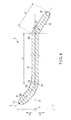
- FIG. 3 and FIG. 4 are diagrams showing the ultrasonic probe 3.
- the ultrasonic probe 3 includes a probe body 21, a distal asymmetric portion 22 provided to the distal-direction side of the probe body 21, and a proximal side probe component 23 provided to the proximal-direction side of the probe body 21.
- a treatment region (treatment section) configured to treat a living tissue is formed in the distal asymmetric portion 22.
- An external thread portion 25 is formed in an outer peripheral portion of the proximal side probe component 23.
- the external thread portion 25 is threaded into the internal thread portion 17 of the horn 15, and the ultrasonic probe 3 is thereby attached to the vibration generating unit 2.
- the ultrasonic vibration generated in the ultrasonic vibrator 12 is transmitted to the ultrasonic probe 3.
- the ultrasonic probe 3 can perform a longitudinal vibration having a vibration direction (vibration directions) and a transmission direction parallel to the central axis C.
- the probe body 21 extends along longitudinal directions.
- the central axis C is coaxial with an X-axis parallel to the longitudinal directions.
- a Y-axis which intersects at right angles with the X-axis, and a Z-axis which intersects at right angles with the X-axis and which intersects at right angles with the Y-axis are defined.
- One of directions parallel to the Y-axis is a first Y-axis direction (direction of an arrow Y1 in FIG. 4 ), and the direction opposite to the first Y-axis direction is a second Y-axis direction (direction of an arrow Y2 in FIG. 4).
- the probe body 21 is shaped symmetrically with an X-Z plane, which is defined by the X-axis and the Z-axis, being a center.
- the distal asymmetric portion 22 includes a curved part 27 which is curved relative to the X-axis toward the first Y-axis direction.
- the provision of the curved part 27 ensures visibility for a surgeon in the treatment of a treatment target with the distal asymmetric portion 22. Since the curved part 27 is provided, the distal asymmetric portion 22 is shaped asymmetrically with the X-Z plane being center. Therefore, the center of gravity of the distal asymmetric portion 22 is located away from the X-axis toward the first Y-axis direction which is one of the directions parallel to the Y-axis.
- the proximal side probe component 23 is bent relative to the probe body 21 at a bending position B1.
- the proximal side probe component 23 extends parallel to the X-Y plane and is tilted relative to the X-axis.
- the proximal side probe component 23 is bent at a bending angle ⁇ 1 with respect to the probe body 21 (X-axis).
- the proximal side probe component 23 is slanted relative to the X-axis toward the second Y-axis direction which is the other of the directions parallel to the Y-axis. Therefore, the center of gravity of the proximal side probe component 23 is located away from the X-axis toward the second Y-axis direction.
- the proximal side probe component 23 extends to the bending position B1 from a proximal end of the ultrasonic probe 3 along the central axis C.
- a first dimension L1 of the probe body 21 along the central axis C (X-axis) is larger than a second dimension L2 of the proximal side probe component 23 along the central axis C. Therefore, the bending position B1 is located in a proximal-direction side part of the ultrasonic probe 3.
- the ultrasonic treatment device 1 and the ultrasonic probe 3 are described.
- a treatment target such as a living tissue is treated with the distal asymmetric portion 22 of the ultrasonic probe 3
- a current is supplied to the ultrasonic vibrator 12 from the ultrasonic generating current supply section 7 via the electric wiring lines 13A and 13B by the operation in the input section 9.
- the ultrasonic vibration is generated in the ultrasonic vibrator 12, and the ultrasonic vibration is transmitted to the ultrasonic probe 3 through the horn 15.
- the ultrasonic probe 3 performs the longitudinal vibration having a vibration direction and a transmission direction parallel to the central axis C.
- the distal asymmetric portion 22 treats the treatment target.
- the treatment target is coagulated and cut by the distal asymmetric portion 22.
- the curved part 27 is provided in the distal asymmetric portion 22, so that the visibility for the surgeon is ensured.
- a jaw which can open and close relative to the distal asymmetric portion 22 may be provided to grasp and thus treat the tissue of the treatment target.
- the distal asymmetric portion 22 is shaped asymmetrically with respect to the X-Z plane. That is, the center of gravity of the distal asymmetric portion 22 is located away from the X-axis toward the first Y-axis direction which is one of the directions parallel to the Y-axis. Because of the asymmetric shape of the distal asymmetric portion 22, a first lateral vibration is superposed on the longitudinal vibration in the ultrasonic probe 3 while the ultrasonic probe 3 is performing the longitudinal vibration.
- the vibration direction (vibration directions) of the first lateral vibration is parallel to the X-Y plane and perpendicular to the central axis C.
- FIG. 5 is a graph showing the change of the first lateral vibration (v1) relative to the change of the position (S) along the central axis C.
- FIG. 6 is a graph showing the change of the first lateral vibration (v1) relative to the change of time (t) at each of positions S1 to S4.
- the positions S1 to S4 correspond to the positions S1 to S4 in FIG. 4 .
- FIG. 5 shows the change of the first lateral vibration (v1) relative to the change of the position (S) along the central axis C when the time (t) is t1, t2, t3, and t4.
- the positions S1 and S3 are anti-node positions of the first lateral vibration
- the positions S2 and S4 are node positions of the first lateral vibration.
- the change of the first lateral vibration relative to the change of time at the position S1 is in anti-phase with respect to the change of the first lateral vibration relative to the change of time at the position S3.
- the change of the first lateral vibration relative to the change of time at the position S2 is in anti-phase with respect to the change of the first lateral vibration relative to the change of time at the position S4.
- the first lateral vibration has a first amplitude V1.
- the proximal side probe component 23 is bent relative to the probe body 21 at the bending position B1 so that the proximal side probe component 23 is parallel to the X-Y plane and inclined relative to the X-axis. That is, the center of gravity of the proximal side probe component 23 is located away from the X-axis toward the second Y-axis direction which is the other of the directions parallel to the Y-axis. Because the proximal side probe component 23 is bent relative to the probe body 21 at the bending position B1, a second lateral vibration is superposed on the longitudinal vibration and the first lateral vibration in the ultrasonic probe 3 while the ultrasonic probe 3 is performing the longitudinal vibration.
- the vibration direction (vibration directions) of the second lateral vibration is parallel to the X-Y plane and perpendicular to the central axis C. That is, the vibration direction of the second lateral vibration is the same as the vibration direction of the first lateral vibration.
- FIG. 7 is a graph showing the change of the second lateral vibration (v2) relative to the change of the position (S) along the central axis C.
- FIG. 8 is a graph showing the change of the second lateral vibration (v2) relative to the change of time (t) at each of the positions S1 to S4.
- the positions S1 to S4 correspond to the positions S1 to S4 in FIG. 4 .
- FIG. 7 shows the change of the second lateral vibration (v2) relative to the change of the position (S) along the central axis C when the time (t) is t1, t2, t3, and t4.
- the positions S1 and S3 are anti-node positions of the second lateral vibration
- the positions S2 and S4 are node positions of the second lateral vibration.
- the change of the second lateral vibration relative to the change of time at the position S1 is in anti-phase with respect to the change of the second lateral vibration relative to the change of time at the position S3.
- the change of the second lateral vibration relative to the change of time at the position S2 is in anti-phase with respect to the change of the second lateral vibration relative to the change of time at the position S4.
- the change of the second lateral vibration relative to the change of time at the position S1 is in anti-phase with respect to the change of the first lateral vibration relative to the change of time at the position S1.
- the second lateral vibration has a second amplitude V2.
- the degree of the second amplitude V2 depends on the bending angle ⁇ 1 of the proximal side probe component 23 with respect to the probe body 21 at the bending position B1.
- the bending angle ⁇ 1 is set so that the second amplitude V2 is the same as the first amplitude V1.
- the second lateral vibration which has the same wavelength and vibration direction as the first lateral vibration and which is in anti-phase with respect to the first lateral vibration, is superposed on the longitudinal vibration in addition to the first lateral vibration. Therefore, the first lateral vibration and the second lateral vibration interfere with each other, so that the influence of the first lateral vibration and the second lateral vibration on the longitudinal vibration of the ultrasonic probe 3 is inhibited. That is, the influence of the first lateral vibration and the second lateral vibration is inhibited in at least the distal asymmetric portion 22.
- the ultrasonic probe 3 vibrates in a vibration mode suitable for the treatment.
- the ultrasonic probe 3 suitably performs the longitudinal vibration, and the longitudinal vibration for use in the treatment is suitably transmitted to the distal asymmetric portion 22. Because the influence of the first lateral vibration and the second lateral vibration is inhibited, the generation of cavitation in the outer circumferential portion of the ultrasonic probe 3 is efficiently prevented, and the deterioration of treatment performance is prevented.
- the second amplitude V2 of the second lateral vibration is the same as the first amplitude V1 of the first lateral vibration. Therefore, the first lateral vibration and the second lateral vibration interfere with each other, so that the influence of the first lateral vibration and the second lateral vibration on the longitudinal vibration of the ultrasonic probe 3 is eliminated. Because the influence of the first lateral vibration and the second lateral vibration is eliminated, the ultrasonic probe 3 more suitably performs the longitudinal vibration, and the longitudinal vibration for use in the treatment is more suitably transmitted to the distal asymmetric portion 22.
- the center of gravity of the distal asymmetric portion 22 is located away from the X-axis toward the first Y-axis direction which is one of the directions parallel to the Y-axis.
- the proximal side probe component 23 is tilted relative to the X-axis toward the second Y-axis direction which is the direction opposite to the first Y-axis direction. Therefore, the center of gravity of the proximal side probe component 23 is located away from the X-axis toward the second Y-axis direction.
- the center of gravity of the distal asymmetric portion 22 is located away from the X-axis toward the first Y-axis direction, and the center of gravity of the proximal side probe component 23 is located away from the X-axis toward the second Y-axis direction, so that the center of gravity of the whole ultrasonic probe 3 is located in the vicinity of the X-axis. Because the center of gravity of the ultrasonic probe 3 is located in the vicinity of the X-axis, the weight balance of the ultrasonic probe 3 is ensured, and the surgeon can easily move the ultrasonic probe 3, for example.
- the first dimension L1 of the probe body 21 along the central axis C is larger than the second dimension L2 of the proximal side probe component 23 along the central axis C. Therefore, the bending position B1 is located in the proximal-direction side part of the ultrasonic probe 3. Because the first dimension L1 along the central axis C of the probe body 21 in which the central axis C is coaxial with the X-axis is larger, the weight balance of the ultrasonic probe 3 is ensured, and the surgeon can easily move the ultrasonic probe 3, for example.
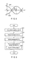
- FIG. 9 is a flowchart showing the manufacturing method of the ultrasonic probe 3.
- a probe preparatory body 3A is first formed (step S101), when the ultrasonic probe 3 is manufactured.
- FIG. 10 is a sectional view of the probe preparatory body 3A in the X-Y plane.
- the X-axis, the Y-axis, and the Z-axis are defined as in the ultrasonic probe 3.
- the probe preparatory body 3A includes a symmetric portion 30 in which the central axis C is coaxial with the X-axis, and a distal asymmetric portion 22 provided to the distal-direction side of the symmetric portion 30.
- the distal asymmetric portion 22 is formed into a shape similar to the shape of the distal asymmetric portion 22 of the ultrasonic probe 3, and serves as the distal asymmetric portion 22 of the ultrasonic probe 3.
- the center of gravity of the distal asymmetric portion 22 is located away from the X-axis toward the first Y-axis direction which is one of the directions parallel to the Y-axis.
- the symmetric portion 30 is shaped symmetrically with the X-Z plane being the center.
- the symmetric portion 30 serves as the probe body 21 and the proximal side probe component 23 of the ultrasonic probe 3.
- the symmetric portion 30 extends from a proximal end of the probe preparatory body 3A along the X-axis (central axis C).
- the probe preparatory body 3A is longitudinally vibrated by the transmission of the ultrasonic vibration to the probe preparatory body 3A.
- the first lateral vibration superposed on the longitudinal vibration is analyzed (step S102). Because of the shape of the distal asymmetric portion 22 which is asymmetric with the X-Z plane being the center, the first lateral vibration is superposed on the longitudinal vibration. Vibration characteristics of the first lateral vibration such as the vibration direction, wavelength, anti-node position, node position, and phase are as have been described with reference to FIG. 5 and FIG. 6 .
- the bending position B1 to bend the symmetric portion 30 is then specified (step S103).
- the symmetric portion 30 is bent so that the proximal side probe component 23 located to the proximal-direction side of the bending position B1 is parallel to the X-Y plane and tilted relative to the X-axis.
- the second lateral vibration is superposed on the longitudinal vibration and the first lateral vibration.
- the second lateral vibration has the same wavelength and vibration direction as the first lateral vibration, and is in anti-phase with the first lateral vibration. Vibration characteristics of the second lateral vibration such as the vibration direction, wavelength, anti-node position, node position, and phase are as have been described with reference to FIG. 7 and FIG. 8 .
- the symmetric portion 30 is bent at a given temporary position, and vibration characteristics when the probe preparatory body 3A bent at the temporary position is longitudinally vibrated are analyzed by a simulation.
- the temporary position to bend the symmetric portion 30 is changed along the central axis C (X-axis) in accordance with, for example, the analyzed vibration characteristics of the first lateral vibration, and the simulation of the vibration characteristics in which the probe preparatory body 3A is longitudinally vibrated is repeated.
- the bending position B1 is specified so that the proximal side probe component 23 located to the proximal-direction side of the bending position B1 is tilted relative to the X-axis toward the second Y-axis direction which is the direction opposite to the first Y-axis direction.
- the bending position B1 is also specified so that the first dimension L1 of the probe body 21 along the central axis C (X-axis) is larger than the second dimension L2 of the proximal side probe component 23 along the central axis C.
- the symmetric portion 30 is then bent at the specified bending position B1 (step S104).
- the probe body 21 and the proximal side probe component 23 of the ultrasonic probe 3 are formed.
- the angle between the probe body 21 (X-axis) and the proximal side probe component 23 at the bending position B1 is adjusted to the bending angle ⁇ 1 (step S105).
- the second amplitude V2 of the second lateral vibration is adjusted to be the same as the first amplitude V1 of the first lateral vibration. In this way, the ultrasonic probe 3 is manufactured.
- the ultrasonic probe 3 having the configuration described above and the manufacturing method of the ultrasonic probe 3 have the following advantageous effects. That is, the proximal side probe component 23 is bent relative to the probe body 21 at the bending position B1 so that the proximal side probe component 23 is parallel to the X-Y plane and slanted relative to the X-axis.
- the second lateral vibration which has the same wavelength and vibration direction as the first lateral vibration and which is in anti-phase with the first lateral vibration, is superposed on the longitudinal vibration in addition to the first lateral vibration.
- the first lateral vibration and the second lateral vibration interfere with each other, so that the influence of the first lateral vibration and the second lateral vibration on the longitudinal vibration of the ultrasonic probe 3 is inhibited.
- the ultrasonic probe 3 vibrates in a vibration mode suitable for the treatment. That is, the ultrasonic probe 3 suitably performs the longitudinal vibration, and the longitudinal vibration for use in the treatment can be suitably transmitted to the distal asymmetric portion 22. Because the influence of the first lateral vibration and the second lateral vibration is inhibited, the generation of cavitation in the outer peripheral portion of the ultrasonic probe 3 is efficiently prevented, and the deterioration of treatment performance is prevented.
- the angle between the probe body 21 and the proximal side probe component 23 at the bending position B1 is adjusted to the bending angle ⁇ 1.
- the second amplitude V2 of the second lateral vibration is adjusted to be the same as the first amplitude V1 of the first lateral vibration. Therefore, the first lateral vibration and the second lateral vibration interfere with each other, so that the influence of the first lateral vibration and the second lateral vibration on the longitudinal vibration of the ultrasonic probe 3 is eliminated. Because the influence of the first lateral vibration and the second lateral vibration is eliminated, the ultrasonic probe 3 more suitably performs the longitudinal vibration, and the longitudinal vibration for use in the treatment can be more suitably transmitted to the distal asymmetric portion 22.
- the proximal side probe component 23 is bent relative to the probe body 21 at the bending position B1 so that the proximal side probe component 23 is tilted relative to the X-axis toward the second Y-axis direction in the first embodiment, this is not a restriction.
- the proximal side probe component 23 may be bent relative to the probe body 21 at a bending position B2.
- the curving of the ultrasonic probe 3 is exaggerated for ease of understanding. Therefore, the degree of this curving is different from that of the actual curving of the ultrasonic probe 3.
- the bending position B2 is a position different from the bending position B1 along the central axis C.
- the proximal side probe component 23 is bent relative to the probe body 21 at the bending position B2 so that the proximal side probe component 23 is parallel to the X-Y plane and tilted relative to the X-axis, as in the first embodiment.
- the proximal side probe component 23 is bent relative to the probe body 21 at the bending position B2 so that the proximal side probe component 23 is slanted relative to the X-axis toward the first Y-axis direction. Therefore, in the present modification, the center of gravity of the distal asymmetric portion 22 is located away from the X-axis toward the first Y-axis direction, and the center of gravity of the proximal side probe component 23 is located away from the X-axis toward the first Y-axis direction. Thus, the center of gravity of the whole ultrasonic probe 3 is located away from the X-axis toward the first Y-axis direction, compared to the first embodiment. In consequence, the weight balance of the ultrasonic probe 3 deteriorates compared to the first embodiment.
- the second lateral vibration is superposed on the longitudinal vibration and the first lateral vibration in the ultrasonic probe 3 while the ultrasonic probe 3 is performing the longitudinal vibration.
- the second lateral vibration has the same wavelength and vibration direction as the first lateral vibration, and is in anti-phase with respect to the first lateral vibration.
- the bending position (B1, B2) to superpose the second lateral vibration on the longitudinal vibration and the first lateral vibration is not limited to one bending position.
- the proximal side probe component 23 is bent at a bending angle ⁇ 2 with respect to the probe body 21 (X-axis). That is, the angle between the probe body 21 and the proximal side probe component 23 at the bending position B2 is adjusted to the bending angle ⁇ 2.
- the second amplitude V2 of the second lateral vibration is adjusted to be the same as the first amplitude V1 of the first lateral vibration.
- the proximal side probe component 23 has only to be bent relative to the probe body 21 at the bending position (B1; B2) so that the proximal side probe component 23 is parallel to the X-Y plane and tilted relative to the X-axis.
- the proximal side probe component 23 is bent relative to the probe body 21 at the bending position (B1; B2), so that when the ultrasonic probe 3 is longitudinally vibrated, the second lateral vibration, which has the same wavelength and vibration direction as the first lateral vibration and which is in anti-phase with respect to the first lateral vibration, has only to be superposed on the longitudinal vibration and the first lateral vibration in the ultrasonic probe 3. Therefore, the first lateral vibration and the second lateral vibration interfere with each other, so that the influence of the first lateral vibration and the second lateral vibration on the longitudinal vibration of the ultrasonic probe 3 is inhibited.
- the distal asymmetric portion 22 includes the curved part 27 in the first embodiment, this is not a restriction.
- the distal asymmetric portion 22 may include a hook-shaped portion 32 instead of the curved part 27.
- the ultrasonic probe performs the longitudinal vibration while the distal asymmetric portion 22 is hooked to a treatment target such as a living tissue, so that a resection of the hooked treatment target is performed.
- the distal asymmetric portion 22 is shaped asymmetrically with the X-Z plane being the center. Because of the asymmetric shape of the distal asymmetric portion 22, the first lateral vibration is superposed on the longitudinal vibration in the ultrasonic probe 3 while the ultrasonic probe 3 is performing the longitudinal vibration.
- the vibration direction (vibration directions) of the first lateral vibration is parallel to the X-Y plane and perpendicular to the central axis C.
- the second lateral vibration which has the same wavelength and vibration direction as the first lateral vibration and which is in anti-phase with respect to the first lateral vibration, is superposed on the longitudinal vibration and the first lateral vibration in the ultrasonic probe 3, as has been described above in the first embodiment.
- the distal asymmetric portion 22 may include a cutout portion 33 instead of the curved part 27.
- the ultrasonic probe performs the longitudinal vibration while the distal asymmetric portion 22 is hooked to a treatment target such as a living tissue, so that the hooked treatment target is resected.
- the distal asymmetric portion 22 is shaped asymmetrically with respect to the X-Z plane. Because of the asymmetric shape of the distal asymmetric portion 22, the first lateral vibration is superposed on the longitudinal vibration in the ultrasonic probe 3 while the ultrasonic probe 3 is performing the longitudinal vibration. The vibration direction of the first lateral vibration is parallel to the X-Y plane and perpendicular to the central axis C.
- the second lateral vibration which has the same wavelength and vibration direction as the first lateral vibration and which is in anti-phase with respect to the first lateral vibration, is superposed on the longitudinal vibration and the first lateral vibration in the ultrasonic probe 3, as has been described above in the first embodiment.
- the distal asymmetric portion 22 has only to be shaped asymmetrically with the X-Z plane being the center. Because of the asymmetric shape of the distal asymmetric portion 22, the first lateral vibration having a vibration direction which is parallel to the X-Y plane and perpendicular to the central axis C has only to be superposed on the longitudinal vibration in the ultrasonic probe 3 by the longitudinal vibration of the ultrasonic probe 3.
Landscapes
- Health & Medical Sciences (AREA)
- Engineering & Computer Science (AREA)
- Life Sciences & Earth Sciences (AREA)
- Surgery (AREA)
- General Health & Medical Sciences (AREA)
- Nuclear Medicine, Radiotherapy & Molecular Imaging (AREA)
- Biomedical Technology (AREA)
- Animal Behavior & Ethology (AREA)
- Public Health (AREA)
- Veterinary Medicine (AREA)
- Mechanical Engineering (AREA)
- Heart & Thoracic Surgery (AREA)
- Medical Informatics (AREA)
- Molecular Biology (AREA)
- Dentistry (AREA)
- Surgical Instruments (AREA)
- Radiology & Medical Imaging (AREA)
Abstract
Description
- The present invention relates to an ultrasonic probe which is used in an ultrasonic treatment device, and which is configured to perform longitudinal vibration having a vibration direction parallel to a central axis when ultrasonic vibration is transmitted thereto, and a manufacturing method of the ultrasonic probe.
- For example,
Patent Literature 1 has disclosed an ultrasonic treatment device including an ultrasonic probe. The ultrasonic probe of this ultrasonic treatment device is configured to perform longitudinal vibration having a vibration direction (vibration directions) parallel to a central axis when ultrasonic vibration is transmitted thereto. According toPatent Literature 1, there are defined an X-axis parallel to longitudinal directions of the ultrasonic probe, a Y-axis which intersects at right angles with the X-axis, and a Z-axis which intersects at right angles with the X-axis and which intersects at right angles with the Y-axis. The ultrasonic probe includes a probe body in which the central axis is coaxial with the X-axis, and a distal asymmetric portion (distal treatment section) provided to a distal direction side of the probe body. The ultrasonic treatment device includes a jaw which can open and close relative to the distal treatment section. The open-and-close directions of the jaw are parallel to the Z-axis. When the ultrasonic probe performs the longitudinal vibration while a treatment target such as a living tissue is grasped between the distal treatment section and the jaw, the grasped treatment target is coagulated and cut, and the treatment target is treated. Here, the probe body is shaped symmetrically with an X-Z plane, which is defined by the X-axis and the Z-axis, being a center. The distal treatment section is curved relative to the probe body in directions parallel to the Y-axis, for example, to ensure visibility for a surgeon during the treatment of the treatment target. Therefore, the distal treatment section is shaped asymmetrically with the X-Z plane, which is defined by the X-axis and the Z-axis, being the center. - Patent Literature 1: Japanese Patent No.
4493893 - The ultrasonic probe according to
Patent Literature 1 includes the probe body shaped symmetrically with the X-Z plane being the center, and the distal treatment section shaped asymmetrically with the X-Z plane being the center. Since the distal treatment section is shaped asymmetrically with respect to the X-Z plane, the center of gravity of the distal treatment section is located away from the X-axis in the directions parallel to the Y-axis. Thus, while the ultrasonic probe is being longitudinally vibrated, a lateral vibration having a vibration direction (vibration directions) perpendicular to the central axis is superposed on the longitudinal vibration. Because of the superposition of the lateral vibration, the ultrasonic probe does not vibrate in a suitable vibration mode, and the longitudinal vibration for use in the treatment of the treatment target is not suitably transmitted to the distal treatment section. That is, the ultrasonic probe vibrates in a vibration mode different from the vibration mode suitable for the treatment of the treatment target. Moreover, because of the superposition of the lateral vibration, treatment performance deteriorates as a result of, for example, a large amount of cavitation generated in an outer peripheral portion of the ultrasonic probe. - The present invention has been made in view of the above-mentioned problems, and an object of the invention is to provide an ultrasonic probe and a manufacturing method of the ultrasonic probe wherein the ultrasonic probe vibrates in a vibration mode suitable for the treatment of a treatment target even when a distal asymmetric portion which superposes a lateral vibration on a longitudinal vibration is provided.
- To solve above mentioned problems, according to one aspect of the invention, a manufacturing method of an ultrasonic probe which extends from a proximal end to a distal end along a central axis and which is configured to perform a longitudinal vibration having a vibration direction parallel to the central axis when an ultrasonic vibration is transmitted thereto, the manufacturing method including: forming a probe preparatory body, the probe preparatory body including a symmetric portion in which the central axis is coaxial with an X-axis, and which is shaped symmetrically with an X-Z plane defined by the X-axis and a Z-axis being a center, when the X-axis is parallel to longitudinal directions, a Y-axis which intersects at right angles with the X-axis, and the Z-axis which intersects at right angles with the X-axis and which intersects at right angles with the Y-axis are defined, and a distal asymmetric portion which is provided to a distal-direction side of the symmetric portion, and which is shaped asymmetrically with the X-Z plane being the center; analyzing a first lateral vibration which is superposed on the longitudinal vibration in the probe preparatory body when the ultrasonic probe is longitudinally vibrated because of an asymmetric shape of the distal asymmetric portion, the first lateral vibration having a vibration direction which is parallel to an X-Y plane defined by the X-axis and the Y-axis and which is perpendicular to the central axis; specifying a bending position to bend the symmetric portion so that a proximal side probe component located to a proximal-direction side of the bending position is parallel to the X-Y plane and tilted relative to the X-axis, a second lateral vibration, which has the same wavelength and vibration direction as the first lateral vibration and which is in anti-phase with respect to the first lateral vibration, being superposed on the longitudinal vibration and the first lateral vibration in the probe preparatory body when the probe preparatory body is longitudinally vibrated while the symmetric portion is bent at the bending position; and bending the symmetric portion at the specified bending position, and thereby forming a probe body in which the central axis is coaxial with an X-axis and which is shaped symmetrically with the X-Z plane being the center, and the proximal side probe component which is bent relative to the probe body.
- According to one another aspect of the invention, An ultrasonic probe which extends from a proximal end to a distal end along a central axis and which is configured to perform a longitudinal vibration having a vibration direction parallel to the central axis when an ultrasonic vibration is transmitted thereto, the ultrasonic probe including: a probe body in which the central axis is coaxial with an X-axis, and which is shaped symmetrically with an X-Z plane defined by the X-axis and a Z-axis being a center, when the X-axis parallel to longitudinal directions, a Y-axis which intersects at right angles with the X-axis, and the Z-axis which intersects at right angles with the X-axis and which intersects at right angles with the Y-axis are defined; a distal asymmetric portion which is provided to a distal-direction side of the probe body, and which is shaped asymmetrically with the X-Z plane being the center, a first lateral vibration, having a vibration direction which is parallel to an X-Y plane defined by the X-axis and the Y-axis and which is perpendicular to the central axis, being superposed on the longitudinal vibration in the ultrasonic probe when the ultrasonic probe is longitudinally vibrated because of an asymmetric shape of the distal asymmetric portion; and a proximal side probe component which is provided to a proximal-direction side of the probe body, and which is bent relative to the probe body at a bending position so that the proximal side probe component is parallel to the X-Y plane and tilted relative to the X-axis, a second lateral vibration, which has the same wavelength and vibration direction as the first lateral vibration and which is in anti-phase with respect to the first lateral vibration, being superposed on the longitudinal vibration and the first lateral vibration in the ultrasonic probe when the ultrasonic probe is longitudinally vibrated because the proximal side probe component is bent relative to the probe body at the bending position.
- According to the present invention, an ultrasonic probe and a manufacturing method of the ultrasonic probe, wherein the ultrasonic probe vibrates in a vibration mode suitable for the treatment of a treatment target even when a distal asymmetric portion which superposes a lateral vibration on a longitudinal vibration is provided, can be provided.
-
-
FIG. 1 is a schematic diagram showing an ultrasonic treatment device according to a first embodiment of the present invention; -
FIG. 2 is a sectional view schematically showing the configuration of a vibration generating unit according to the first embodiment; -
FIG. 3 is a perspective view schematically showing the configuration of an ultrasonic probe according to the first embodiment; -
FIG. 4 is a sectional view schematically showing the configuration of the ultrasonic probe according to the first embodiment; -
FIG. 5 is a schematic diagram showing the change of a first lateral vibration relative to the change of the position along the central axis of the ultrasonic probe according to the first embodiment; -
FIG. 6 is a schematic diagram showing the change of a first lateral vibration relative to the change of time at each of the positions along the central axis of the ultrasonic probe according to the first embodiment; -
FIG. 7 is a schematic diagram showing the change of a second lateral vibration relative to the change of the position along the central axis of the ultrasonic probe according to the first embodiment; -
FIG. 8 is a schematic diagram showing the change of a second lateral vibration relative to the change of time at each of the positions along the central axis of the ultrasonic probe according to the first embodiment; -
FIG. 9 is a flowchart showing a manufacturing method of the ultrasonic probe according to the first embodiment; -
FIG. 10 is a sectional view schematically showing the configuration of a probe preparatory body according to the first embodiment; -
FIG. 11 is a sectional view schematically showing the configuration of an ultrasonic probe according to a first modification; -
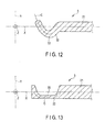
FIG. 12 is a sectional view schematically showing the configuration of a distal asymmetric portion of an ultrasonic probe according to a second modification; and -
FIG. 13 is a sectional view schematically showing the configuration of a distal asymmetric portion of an ultrasonic probe according to a third modification. - A first embodiment of the present invention is described with reference to
FIG. 1 to FIG. 10 .FIG. 1 is a diagram showing anultrasonic treatment device 1 according to the present embodiment. As shown inFIG. 1 , theultrasonic treatment apparatus 1 has a central axis C. Here, one of two directions parallel to the central axis C is a distal direction (direction of an arrow C1 inFIG. 1 ), and the direction opposite to the distal direction is a proximal direction (direction of an arrow C2 inFIG. 1 ). Theultrasonic treatment device 1 includes a vibration generatingunit 2, and anultrasonic probe 3 extending from a proximal end to a distal end along the central axis C. InFIG. 1 ,FIG. 3 ,FIG. 4 , andFIG. 10 , the curving of theultrasonic probe 3 is exaggerated for ease of understanding. Therefore, the degree of this curving is different from that of the actual curving of theultrasonic probe 3. - The vibration generating
unit 2 includes avibrator case 11. One end of acable 5 is connected to the proximal end of thevibrator case 11. The other end of thecable 5 is connected to apower supply unit 6. Thepower supply unit 6 includes an ultrasonic generating current supply section 7, and aninput section 9. -
FIG. 2 is a diagram showing the configuration of the vibration generatingunit 2. As shown inFIG. 2 , anultrasonic vibrator 12, which is a vibration generator including a piezoelectric element configured to convert a current to an ultrasonic vibration, is provided inside thetransducer case 11. One end of each ofelectric wiring lines ultrasonic transducer 12. Each of theelectric wiring lines power supply unit 6 through an inside of thecable 5. The ultrasonic vibration is generated in theultrasonic vibrator 12 by the supply of a current to theultrasonic oscillator 12 from the ultrasonic generating current supply section 7 via theelectric wiring lines horn 15 which is configured to increase the amplitude of the ultrasonic vibration is coupled to the distal-direction side of theultrasonic vibrator 12. Thehorn 15 is attached to theoscillator case 11. Aninternal thread portion 17 is formed in a distal portion of thehorn 15. -
FIG. 3 andFIG. 4 are diagrams showing theultrasonic probe 3. As shown inFIG. 3 andFIG. 4 , theultrasonic probe 3 includes aprobe body 21, a distalasymmetric portion 22 provided to the distal-direction side of theprobe body 21, and a proximalside probe component 23 provided to the proximal-direction side of theprobe body 21. A treatment region (treatment section) configured to treat a living tissue is formed in the distalasymmetric portion 22. - An
external thread portion 25 is formed in an outer peripheral portion of the proximalside probe component 23. Theexternal thread portion 25 is threaded into theinternal thread portion 17 of thehorn 15, and theultrasonic probe 3 is thereby attached to the vibration generatingunit 2. When theultrasonic probe 3 is attached to thevibration generating unit 2, the ultrasonic vibration generated in theultrasonic vibrator 12 is transmitted to theultrasonic probe 3. When the ultrasonic vibration is transmitted to theultrasonic probe 3, theultrasonic probe 3 can perform a longitudinal vibration having a vibration direction (vibration directions) and a transmission direction parallel to the central axis C. - The
probe body 21 extends along longitudinal directions. In theprobe body 21, the central axis C is coaxial with an X-axis parallel to the longitudinal directions. Here, a Y-axis which intersects at right angles with the X-axis, and a Z-axis which intersects at right angles with the X-axis and which intersects at right angles with the Y-axis are defined. One of directions parallel to the Y-axis is a first Y-axis direction (direction of an arrow Y1 inFIG. 4 ), and the direction opposite to the first Y-axis direction is a second Y-axis direction (direction of an arrow Y2 inFIG. 4). FIG. 4 shows a sectional view of theultrasonic probe 3 in an X-Y plane defined by the X-axis and the Y-axis. Theprobe body 21 is shaped symmetrically with an X-Z plane, which is defined by the X-axis and the Z-axis, being a center. - The distal
asymmetric portion 22 includes acurved part 27 which is curved relative to the X-axis toward the first Y-axis direction. The provision of thecurved part 27 ensures visibility for a surgeon in the treatment of a treatment target with the distalasymmetric portion 22. Since thecurved part 27 is provided, the distalasymmetric portion 22 is shaped asymmetrically with the X-Z plane being center. Therefore, the center of gravity of the distalasymmetric portion 22 is located away from the X-axis toward the first Y-axis direction which is one of the directions parallel to the Y-axis. - The proximal
side probe component 23 is bent relative to theprobe body 21 at a bending position B1. The proximalside probe component 23 extends parallel to the X-Y plane and is tilted relative to the X-axis. At the bending position B1, the proximalside probe component 23 is bent at a bending angle α1 with respect to the probe body 21 (X-axis). The proximalside probe component 23 is slanted relative to the X-axis toward the second Y-axis direction which is the other of the directions parallel to the Y-axis. Therefore, the center of gravity of the proximalside probe component 23 is located away from the X-axis toward the second Y-axis direction. - The proximal
side probe component 23 extends to the bending position B1 from a proximal end of theultrasonic probe 3 along the central axis C. A first dimension L1 of theprobe body 21 along the central axis C (X-axis) is larger than a second dimension L2 of the proximalside probe component 23 along the central axis C. Therefore, the bending position B1 is located in a proximal-direction side part of theultrasonic probe 3. - Now, the functions of the
ultrasonic treatment device 1 and theultrasonic probe 3 are described. When a treatment target such as a living tissue is treated with the distalasymmetric portion 22 of theultrasonic probe 3, a current is supplied to theultrasonic vibrator 12 from the ultrasonic generating current supply section 7 via theelectric wiring lines input section 9. As a result, the ultrasonic vibration is generated in theultrasonic vibrator 12, and the ultrasonic vibration is transmitted to theultrasonic probe 3 through thehorn 15. When the ultrasonic vibration is transmitted to theultrasonic probe 3, theultrasonic probe 3 performs the longitudinal vibration having a vibration direction and a transmission direction parallel to the central axis C. While theultrasonic probe 3 is performing the longitudinal vibration, the distalasymmetric portion 22 treats the treatment target. For example, when theultrasonic probe 3 performs the longitudinal vibration while the distalasymmetric portion 22 is in contact with the treatment target, the treatment target is coagulated and cut by the distalasymmetric portion 22. In this case, thecurved part 27 is provided in the distalasymmetric portion 22, so that the visibility for the surgeon is ensured. Although not shown, a jaw which can open and close relative to the distalasymmetric portion 22 may be provided to grasp and thus treat the tissue of the treatment target. - Here, since the
curved part 27 is provided, the distalasymmetric portion 22 is shaped asymmetrically with respect to the X-Z plane. That is, the center of gravity of the distalasymmetric portion 22 is located away from the X-axis toward the first Y-axis direction which is one of the directions parallel to the Y-axis. Because of the asymmetric shape of the distalasymmetric portion 22, a first lateral vibration is superposed on the longitudinal vibration in theultrasonic probe 3 while theultrasonic probe 3 is performing the longitudinal vibration. The vibration direction (vibration directions) of the first lateral vibration is parallel to the X-Y plane and perpendicular to the central axis C. -
FIG. 5 is a graph showing the change of the first lateral vibration (v1) relative to the change of the position (S) along the central axis C.FIG. 6 is a graph showing the change of the first lateral vibration (v1) relative to the change of time (t) at each of positions S1 to S4. Here, the positions S1 to S4 correspond to the positions S1 to S4 inFIG. 4 .FIG. 5 shows the change of the first lateral vibration (v1) relative to the change of the position (S) along the central axis C when the time (t) is t1, t2, t3, and t4. - As shown in
FIG. 5 and FIG. 6 , the positions S1 and S3 are anti-node positions of the first lateral vibration, and the positions S2 and S4 are node positions of the first lateral vibration. The change of the first lateral vibration relative to the change of time at the position S1 is in anti-phase with respect to the change of the first lateral vibration relative to the change of time at the position S3. The change of the first lateral vibration relative to the change of time at the position S2 is in anti-phase with respect to the change of the first lateral vibration relative to the change of time at the position S4. The first lateral vibration has a first amplitude V1. - The proximal
side probe component 23 is bent relative to theprobe body 21 at the bending position B1 so that the proximalside probe component 23 is parallel to the X-Y plane and inclined relative to the X-axis. That is, the center of gravity of the proximalside probe component 23 is located away from the X-axis toward the second Y-axis direction which is the other of the directions parallel to the Y-axis. Because the proximalside probe component 23 is bent relative to theprobe body 21 at the bending position B1, a second lateral vibration is superposed on the longitudinal vibration and the first lateral vibration in theultrasonic probe 3 while theultrasonic probe 3 is performing the longitudinal vibration. The vibration direction (vibration directions) of the second lateral vibration is parallel to the X-Y plane and perpendicular to the central axis C. That is, the vibration direction of the second lateral vibration is the same as the vibration direction of the first lateral vibration. -
FIG. 7 is a graph showing the change of the second lateral vibration (v2) relative to the change of the position (S) along the central axis C.FIG. 8 is a graph showing the change of the second lateral vibration (v2) relative to the change of time (t) at each of the positions S1 to S4. Here, the positions S1 to S4 correspond to the positions S1 to S4 inFIG. 4 .FIG. 7 shows the change of the second lateral vibration (v2) relative to the change of the position (S) along the central axis C when the time (t) is t1, t2, t3, and t4. - As shown in
FIG. 7 andFIG. 8 , the positions S1 and S3 are anti-node positions of the second lateral vibration, and the positions S2 and S4 are node positions of the second lateral vibration. The change of the second lateral vibration relative to the change of time at the position S1 is in anti-phase with respect to the change of the second lateral vibration relative to the change of time at the position S3. The change of the second lateral vibration relative to the change of time at the position S2 is in anti-phase with respect to the change of the second lateral vibration relative to the change of time at the position S4. - Compared to the first lateral vibration (
FIG. 5 and FIG. 6 ), the change of the second lateral vibration relative to the change of time at the position S1 is in anti-phase with respect to the change of the first lateral vibration relative to the change of time at the position S1. The same applies to the positions S2 to S4. That is, the wavelength of the second lateral vibration is the same as the wavelength of the first lateral vibration, and the second lateral vibration is in anti-phase with respect to the first lateral vibration. - The second lateral vibration has a second amplitude V2. The degree of the second amplitude V2 depends on the bending angle α1 of the proximal
side probe component 23 with respect to theprobe body 21 at the bending position B1. The bending angle α1 is set so that the second amplitude V2 is the same as the first amplitude V1. - As described above, while the
ultrasonic probe 3 is performing the longitudinal vibration, the second lateral vibration, which has the same wavelength and vibration direction as the first lateral vibration and which is in anti-phase with respect to the first lateral vibration, is superposed on the longitudinal vibration in addition to the first lateral vibration. Therefore, the first lateral vibration and the second lateral vibration interfere with each other, so that the influence of the first lateral vibration and the second lateral vibration on the longitudinal vibration of theultrasonic probe 3 is inhibited. That is, the influence of the first lateral vibration and the second lateral vibration is inhibited in at least the distalasymmetric portion 22. When the influence of the first lateral vibration and the second lateral vibration is thus inhibited, theultrasonic probe 3 vibrates in a vibration mode suitable for the treatment. That is, theultrasonic probe 3 suitably performs the longitudinal vibration, and the longitudinal vibration for use in the treatment is suitably transmitted to the distalasymmetric portion 22. Because the influence of the first lateral vibration and the second lateral vibration is inhibited, the generation of cavitation in the outer circumferential portion of theultrasonic probe 3 is efficiently prevented, and the deterioration of treatment performance is prevented. - The second amplitude V2 of the second lateral vibration is the same as the first amplitude V1 of the first lateral vibration. Therefore, the first lateral vibration and the second lateral vibration interfere with each other, so that the influence of the first lateral vibration and the second lateral vibration on the longitudinal vibration of the
ultrasonic probe 3 is eliminated. Because the influence of the first lateral vibration and the second lateral vibration is eliminated, theultrasonic probe 3 more suitably performs the longitudinal vibration, and the longitudinal vibration for use in the treatment is more suitably transmitted to the distalasymmetric portion 22. - The center of gravity of the distal
asymmetric portion 22 is located away from the X-axis toward the first Y-axis direction which is one of the directions parallel to the Y-axis. The proximalside probe component 23 is tilted relative to the X-axis toward the second Y-axis direction which is the direction opposite to the first Y-axis direction. Therefore, the center of gravity of the proximalside probe component 23 is located away from the X-axis toward the second Y-axis direction. The center of gravity of the distalasymmetric portion 22 is located away from the X-axis toward the first Y-axis direction, and the center of gravity of the proximalside probe component 23 is located away from the X-axis toward the second Y-axis direction, so that the center of gravity of the wholeultrasonic probe 3 is located in the vicinity of the X-axis. Because the center of gravity of theultrasonic probe 3 is located in the vicinity of the X-axis, the weight balance of theultrasonic probe 3 is ensured, and the surgeon can easily move theultrasonic probe 3, for example. - The first dimension L1 of the
probe body 21 along the central axis C is larger than the second dimension L2 of the proximalside probe component 23 along the central axis C. Therefore, the bending position B1 is located in the proximal-direction side part of theultrasonic probe 3. Because the first dimension L1 along the central axis C of theprobe body 21 in which the central axis C is coaxial with the X-axis is larger, the weight balance of theultrasonic probe 3 is ensured, and the surgeon can easily move theultrasonic probe 3, for example. - Now, a manufacturing method of the
ultrasonic probe 3 is described.FIG. 9 is a flowchart showing the manufacturing method of theultrasonic probe 3. As shown inFIG. 9 , a probepreparatory body 3A is first formed (step S101), when theultrasonic probe 3 is manufactured. -
FIG. 10 is a sectional view of the probepreparatory body 3A in the X-Y plane. In the probepreparatory body 3A, the X-axis, the Y-axis, and the Z-axis are defined as in theultrasonic probe 3. As shown inFIG. 10 , the probepreparatory body 3A includes asymmetric portion 30 in which the central axis C is coaxial with the X-axis, and a distalasymmetric portion 22 provided to the distal-direction side of thesymmetric portion 30. The distalasymmetric portion 22 is formed into a shape similar to the shape of the distalasymmetric portion 22 of theultrasonic probe 3, and serves as the distalasymmetric portion 22 of theultrasonic probe 3. Therefore, the center of gravity of the distalasymmetric portion 22 is located away from the X-axis toward the first Y-axis direction which is one of the directions parallel to the Y-axis. Thesymmetric portion 30 is shaped symmetrically with the X-Z plane being the center. Thesymmetric portion 30 serves as theprobe body 21 and the proximalside probe component 23 of theultrasonic probe 3. Thesymmetric portion 30 extends from a proximal end of the probepreparatory body 3A along the X-axis (central axis C). - After the probe
preparatory body 3A is formed, the probepreparatory body 3A is longitudinally vibrated by the transmission of the ultrasonic vibration to the probepreparatory body 3A. As shown inFIG. 9 , while the probepreparatory body 3A is being longitudinally vibrated, the first lateral vibration superposed on the longitudinal vibration is analyzed (step S102). Because of the shape of the distalasymmetric portion 22 which is asymmetric with the X-Z plane being the center, the first lateral vibration is superposed on the longitudinal vibration. Vibration characteristics of the first lateral vibration such as the vibration direction, wavelength, anti-node position, node position, and phase are as have been described with reference toFIG. 5 and FIG. 6 . - The bending position B1 to bend the
symmetric portion 30 is then specified (step S103). At the bending position B1, thesymmetric portion 30 is bent so that the proximalside probe component 23 located to the proximal-direction side of the bending position B1 is parallel to the X-Y plane and tilted relative to the X-axis. When the probepreparatory body 3A is longitudinally vibrated while thesymmetric portion 30 is bent at the bending position B1, the second lateral vibration is superposed on the longitudinal vibration and the first lateral vibration. The second lateral vibration has the same wavelength and vibration direction as the first lateral vibration, and is in anti-phase with the first lateral vibration. Vibration characteristics of the second lateral vibration such as the vibration direction, wavelength, anti-node position, node position, and phase are as have been described with reference toFIG. 7 andFIG. 8 . - To specify the bending position B1, for example, the
symmetric portion 30 is bent at a given temporary position, and vibration characteristics when the probepreparatory body 3A bent at the temporary position is longitudinally vibrated are analyzed by a simulation. The temporary position to bend thesymmetric portion 30 is changed along the central axis C (X-axis) in accordance with, for example, the analyzed vibration characteristics of the first lateral vibration, and the simulation of the vibration characteristics in which the probepreparatory body 3A is longitudinally vibrated is repeated. - In the present embodiment, the bending position B1 is specified so that the proximal
side probe component 23 located to the proximal-direction side of the bending position B1 is tilted relative to the X-axis toward the second Y-axis direction which is the direction opposite to the first Y-axis direction. The bending position B1 is also specified so that the first dimension L1 of theprobe body 21 along the central axis C (X-axis) is larger than the second dimension L2 of the proximalside probe component 23 along the central axis C. - The
symmetric portion 30 is then bent at the specified bending position B1 (step S104). As a result, theprobe body 21 and the proximalside probe component 23 of theultrasonic probe 3 are formed. In this case, the angle between the probe body 21 (X-axis) and the proximalside probe component 23 at the bending position B1 is adjusted to the bending angle α1 (step S105). As a result, the second amplitude V2 of the second lateral vibration is adjusted to be the same as the first amplitude V1 of the first lateral vibration. In this way, theultrasonic probe 3 is manufactured. - Accordingly, the
ultrasonic probe 3 having the configuration described above and the manufacturing method of theultrasonic probe 3 have the following advantageous effects. That is, the proximalside probe component 23 is bent relative to theprobe body 21 at the bending position B1 so that the proximalside probe component 23 is parallel to the X-Y plane and slanted relative to the X-axis. Thus, while theultrasonic probe 3 is performing the longitudinal vibration, the second lateral vibration, which has the same wavelength and vibration direction as the first lateral vibration and which is in anti-phase with the first lateral vibration, is superposed on the longitudinal vibration in addition to the first lateral vibration. Therefore, the first lateral vibration and the second lateral vibration interfere with each other, so that the influence of the first lateral vibration and the second lateral vibration on the longitudinal vibration of theultrasonic probe 3 is inhibited. Because the influence of the first lateral vibration and the second lateral vibration is inhibited, theultrasonic probe 3 vibrates in a vibration mode suitable for the treatment. That is, theultrasonic probe 3 suitably performs the longitudinal vibration, and the longitudinal vibration for use in the treatment can be suitably transmitted to the distalasymmetric portion 22. Because the influence of the first lateral vibration and the second lateral vibration is inhibited, the generation of cavitation in the outer peripheral portion of theultrasonic probe 3 is efficiently prevented, and the deterioration of treatment performance is prevented. - In the
ultrasonic probe 3, the angle between theprobe body 21 and the proximalside probe component 23 at the bending position B1 is adjusted to the bending angle α1. As a result, the second amplitude V2 of the second lateral vibration is adjusted to be the same as the first amplitude V1 of the first lateral vibration. Therefore, the first lateral vibration and the second lateral vibration interfere with each other, so that the influence of the first lateral vibration and the second lateral vibration on the longitudinal vibration of theultrasonic probe 3 is eliminated. Because the influence of the first lateral vibration and the second lateral vibration is eliminated, theultrasonic probe 3 more suitably performs the longitudinal vibration, and the longitudinal vibration for use in the treatment can be more suitably transmitted to the distalasymmetric portion 22. - Although the proximal
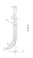
side probe component 23 is bent relative to theprobe body 21 at the bending position B1 so that the proximalside probe component 23 is tilted relative to the X-axis toward the second Y-axis direction in the first embodiment, this is not a restriction. For example, as in a first modification shown inFIG. 11 , the proximalside probe component 23 may be bent relative to theprobe body 21 at a bending position B2. InFIG. 11 , the curving of theultrasonic probe 3 is exaggerated for ease of understanding. Therefore, the degree of this curving is different from that of the actual curving of theultrasonic probe 3. - The bending position B2 is a position different from the bending position B1 along the central axis C. In the present modification, the proximal
side probe component 23 is bent relative to theprobe body 21 at the bending position B2 so that the proximalside probe component 23 is parallel to the X-Y plane and tilted relative to the X-axis, as in the first embodiment. - However, in the present modification, the proximal
side probe component 23 is bent relative to theprobe body 21 at the bending position B2 so that the proximalside probe component 23 is slanted relative to the X-axis toward the first Y-axis direction. Therefore, in the present modification, the center of gravity of the distalasymmetric portion 22 is located away from the X-axis toward the first Y-axis direction, and the center of gravity of the proximalside probe component 23 is located away from the X-axis toward the first Y-axis direction. Thus, the center of gravity of the wholeultrasonic probe 3 is located away from the X-axis toward the first Y-axis direction, compared to the first embodiment. In consequence, the weight balance of theultrasonic probe 3 deteriorates compared to the first embodiment. - In the present modification, because the proximal
side probe component 23 is bent relative to theprobe body 21 at the bending position B2, the second lateral vibration is superposed on the longitudinal vibration and the first lateral vibration in theultrasonic probe 3 while theultrasonic probe 3 is performing the longitudinal vibration. As has been described above in the first embodiment, the second lateral vibration has the same wavelength and vibration direction as the first lateral vibration, and is in anti-phase with respect to the first lateral vibration. As described above, the bending position (B1, B2) to superpose the second lateral vibration on the longitudinal vibration and the first lateral vibration is not limited to one bending position. - At the bending position B2, the proximal
side probe component 23 is bent at a bending angle α2 with respect to the probe body 21 (X-axis). That is, the angle between theprobe body 21 and the proximalside probe component 23 at the bending position B2 is adjusted to the bending angle α2. As a result, the second amplitude V2 of the second lateral vibration is adjusted to be the same as the first amplitude V1 of the first lateral vibration. - According to the first modification described above, the proximal
side probe component 23 has only to be bent relative to theprobe body 21 at the bending position (B1; B2) so that the proximalside probe component 23 is parallel to the X-Y plane and tilted relative to the X-axis. The proximalside probe component 23 is bent relative to theprobe body 21 at the bending position (B1; B2), so that when theultrasonic probe 3 is longitudinally vibrated, the second lateral vibration, which has the same wavelength and vibration direction as the first lateral vibration and which is in anti-phase with respect to the first lateral vibration, has only to be superposed on the longitudinal vibration and the first lateral vibration in theultrasonic probe 3. Therefore, the first lateral vibration and the second lateral vibration interfere with each other, so that the influence of the first lateral vibration and the second lateral vibration on the longitudinal vibration of theultrasonic probe 3 is inhibited. - Although the distal
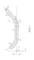
asymmetric portion 22 includes thecurved part 27 in the first embodiment, this is not a restriction. For example, as in a second modification shown inFIG. 12 , the distalasymmetric portion 22 may include a hook-shapedportion 32 instead of thecurved part 27. In the present modification, for example, the ultrasonic probe performs the longitudinal vibration while the distalasymmetric portion 22 is hooked to a treatment target such as a living tissue, so that a resection of the hooked treatment target is performed. - Since the hook-shaped
portion 32 is provided, the distalasymmetric portion 22 is shaped asymmetrically with the X-Z plane being the center. Because of the asymmetric shape of the distalasymmetric portion 22, the first lateral vibration is superposed on the longitudinal vibration in theultrasonic probe 3 while theultrasonic probe 3 is performing the longitudinal vibration. The vibration direction (vibration directions) of the first lateral vibration is parallel to the X-Y plane and perpendicular to the central axis C. In the present modification, when theultrasonic probe 3 is longitudinally vibrated, the second lateral vibration, which has the same wavelength and vibration direction as the first lateral vibration and which is in anti-phase with respect to the first lateral vibration, is superposed on the longitudinal vibration and the first lateral vibration in theultrasonic probe 3, as has been described above in the first embodiment. - Moreover, for example, as in a third modification shown in
FIG. 13 , the distalasymmetric portion 22 may include acutout portion 33 instead of thecurved part 27. In the present modification, for example, the ultrasonic probe performs the longitudinal vibration while the distalasymmetric portion 22 is hooked to a treatment target such as a living tissue, so that the hooked treatment target is resected. - Since the
cutout portion 33 is provided, the distalasymmetric portion 22 is shaped asymmetrically with respect to the X-Z plane. Because of the asymmetric shape of the distalasymmetric portion 22, the first lateral vibration is superposed on the longitudinal vibration in theultrasonic probe 3 while theultrasonic probe 3 is performing the longitudinal vibration. The vibration direction of the first lateral vibration is parallel to the X-Y plane and perpendicular to the central axis C. In the present modification, when theultrasonic probe 3 is longitudinally vibrated, the second lateral vibration, which has the same wavelength and vibration direction as the first lateral vibration and which is in anti-phase with respect to the first lateral vibration, is superposed on the longitudinal vibration and the first lateral vibration in theultrasonic probe 3, as has been described above in the first embodiment. - According to the second modification and the third modification described above, the distal
asymmetric portion 22 has only to be shaped asymmetrically with the X-Z plane being the center. Because of the asymmetric shape of the distalasymmetric portion 22, the first lateral vibration having a vibration direction which is parallel to the X-Y plane and perpendicular to the central axis C has only to be superposed on the longitudinal vibration in theultrasonic probe 3 by the longitudinal vibration of theultrasonic probe 3. - Incidentally, the present invention is not limited to the above embodiments and various modifications can naturally be made without deviating from the spirit and scope of the present invention.
Claims (8)
- A manufacturing method of an ultrasonic probe which extends from a proximal end to a distal end along a central axis and which is configured to perform a longitudinal vibration having a vibration direction parallel to the central axis when an ultrasonic vibration is transmitted thereto, the manufacturing method comprising:forming a probe preparatory body, the probe preparatory body including a symmetric portion in which the central axis is coaxial with an X-axis, and which is shaped symmetrically with an X-Z plane defined by the X-axis and a Z-axis being a center, when the X-axis is parallel to longitudinal directions, a Y-axis which intersects at right angles with the X-axis, and the Z-axis which intersects at right angles with the X-axis and which intersects at right angles with the Y-axis are defined, and a distal asymmetric portion which is provided to a distal-direction side of the symmetric portion, and which is shaped asymmetrically with the X-Z plane being the center;analyzing a first lateral vibration which is superposed on the longitudinal vibration in the probe preparatory body when the ultrasonic probe is longitudinally vibrated because of an asymmetric shape of the distal asymmetric portion, the first lateral vibration having a vibration direction which is parallel to an X-Y plane defined by the X-axis and the Y-axis and which is perpendicular to the central axis;specifying a bending position to bend the symmetric portion so that a proximal side probe component located to a proximal-direction side of the bending position is parallel to the X-Y plane and tilted relative to the X-axis, a second lateral vibration, which has the same wavelength and vibration direction as the first lateral vibration and which is in anti-phase with respect to the first lateral vibration, being superposed on the longitudinal vibration and the first lateral vibration in the probe preparatory body when the probe preparatory body is longitudinally vibrated while the symmetric portion is bent at the bending position; andbending the symmetric portion at the specified bending position, and thereby forming a probe body in which the central axis is coaxial with an X-axis and which is shaped symmetrically with the X-Z plane being the center, and the proximal side probe component which is bent relative to the probe body.
- The manufacturing method according to claim 1, wherein bending the symmetric portion includes adjusting a bending angle between the probe body and the proximal side probe component at the bending position so that a first amplitude of the first lateral vibration and a second amplitude of the second lateral vibration are the same.
- The manufacturing method according to claim 1, wherein forming the probe preparatory body includes forming the distal asymmetric portion so that a center of gravity of the distal asymmetric portion is located away from the X-axis toward a first Y-axis direction which is one of directions parallel to the Y-axis, and
specifying the bending position in the symmetric portion includes specifying the bending position so that the proximal side probe component is tilted relative to the X-axis toward a second Y-axis direction which is a direction opposite to the first Y-axis direction. - The manufacturing method according to claim 1, wherein forming the probe preparatory body includes forming the symmetric portion so that the symmetric portion extends from a proximal end of the probe preparatory body along the X-axis, and
specifying the bending position in the symmetric portion include specifying the bending position so that a first dimension of the probe body along the central axis is larger than a second dimension of the proximal side probe component along the central axis. - An ultrasonic probe which extends from a proximal end to a distal end along a central axis and which is configured to perform a longitudinal vibration having a vibration direction parallel to the central axis when an ultrasonic vibration is transmitted thereto, the ultrasonic probe comprising:a probe body in which the central axis is coaxial with an X-axis, and which is shaped symmetrically with an X-Z plane defined by the X-axis and a Z-axis being a center, when the X-axis parallel to longitudinal directions, a Y-axis which intersects at right angles with the X-axis, and the Z-axis which intersects at right angles with the X-axis and which intersects at right angles with the Y-axis are defined;a distal asymmetric portion which is provided to a distal-direction side of the probe body, and which is shaped asymmetrically with the X-Z plane being the center, a first lateral vibration, having a vibration direction which is parallel to an X-Y plane defined by the X-axis and the Y-axis and which is perpendicular to the central axis, being superposed on the longitudinal vibration in the ultrasonic probe when the ultrasonic probe is longitudinally vibrated because of an asymmetric shape of the distal asymmetric portion; anda proximal side probe component which is provided to a proximal-direction side of the probe body, and which is bent relative to the probe body at a bending position so that the proximal side probe component is parallel to the X-Y plane and tilted relative to the X-axis, a second lateral vibration, which has the same wavelength and vibration direction as the first lateral vibration and which is in anti-phase with respect to the first lateral vibration, being superposed on the longitudinal vibration and the first lateral vibration in the ultrasonic probe when the ultrasonic probe is longitudinally vibrated because the proximal side probe component is bent relative to the probe body at the bending position.
- The ultrasonic probe according to claim 5, wherein the proximal side probe component is bent relative to the probe body at the bending position at a bending angle such that a first amplitude of the first lateral vibration and a second amplitude of the second lateral vibration are the same.
- The ultrasonic probe according to claim 5, wherein a center of gravity of the distal asymmetric portion is located away from the X-axis toward a first Y-axis direction which is one of directions parallel to the Y-axis, and
the proximal side probe component is bent relative to the probe body at the bending position so that the proximal side probe component is tilted relative to the X-axis toward a second Y-axis direction which is a direction opposite to the first Y-axis direction. - The ultrasonic probe according to claim 5, wherein the proximal side probe component extends from the proximal end of the ultrasonic probe along the central axis, and
a first dimension of the probe body along the central axis is larger than a second dimension of the proximal side probe component along the central axis.
Applications Claiming Priority (2)
| Application Number | Priority Date | Filing Date | Title |
|---|---|---|---|
| US201261656163P | 2012-06-06 | 2012-06-06 | |
| PCT/JP2013/065716 WO2013183714A1 (en) | 2012-06-06 | 2013-06-06 | Ultrasound probe, and ultrasound-probe production method |
Publications (3)
| Publication Number | Publication Date |
|---|---|
| EP2859858A1 true EP2859858A1 (en) | 2015-04-15 |
| EP2859858A4 EP2859858A4 (en) | 2016-03-23 |
| EP2859858B1 EP2859858B1 (en) | 2016-12-28 |
Family
ID=49712102
Family Applications (1)
| Application Number | Title | Priority Date | Filing Date |
|---|---|---|---|
| EP13800457.7A Not-in-force EP2859858B1 (en) | 2012-06-06 | 2013-06-06 | Ultrasound probe |
Country Status (5)
| Country | Link |
|---|---|
| US (1) | US9265973B2 (en) |
| EP (1) | EP2859858B1 (en) |
| JP (1) | JP5572780B2 (en) |
| CN (1) | CN104349737B (en) |
| WO (1) | WO2013183714A1 (en) |
Cited By (20)
| Publication number | Priority date | Publication date | Assignee | Title |
|---|---|---|---|---|
| WO2016204999A1 (en) * | 2015-06-17 | 2016-12-22 | Ethicon Endo-Surgery, Llc | Ultrasonic surgical blade for use with ultrasonic surgical instruments |
| US10335182B2 (en) | 2012-06-29 | 2019-07-02 | Ethicon Llc | Surgical instruments with articulating shafts |
| US10335183B2 (en) | 2012-06-29 | 2019-07-02 | Ethicon Llc | Feedback devices for surgical control systems |
| US10335614B2 (en) | 2008-08-06 | 2019-07-02 | Ethicon Llc | Devices and techniques for cutting and coagulating tissue |
| US10342602B2 (en) | 2015-03-17 | 2019-07-09 | Ethicon Llc | Managing tissue treatment |
| US10349999B2 (en) | 2014-03-31 | 2019-07-16 | Ethicon Llc | Controlling impedance rise in electrosurgical medical devices |
| US10357303B2 (en) | 2015-06-30 | 2019-07-23 | Ethicon Llc | Translatable outer tube for sealing using shielded lap chole dissector |
| US10376305B2 (en) | 2016-08-05 | 2019-08-13 | Ethicon Llc | Methods and systems for advanced harmonic energy |
| US10398466B2 (en) | 2007-07-27 | 2019-09-03 | Ethicon Llc | Ultrasonic end effectors with increased active length |
| US10398497B2 (en) | 2012-06-29 | 2019-09-03 | Ethicon Llc | Lockout mechanism for use with robotic electrosurgical device |
| US10420579B2 (en) | 2007-07-31 | 2019-09-24 | Ethicon Llc | Surgical instruments |
| US10420580B2 (en) | 2016-08-25 | 2019-09-24 | Ethicon Llc | Ultrasonic transducer for surgical instrument |
| US10426507B2 (en) | 2007-07-31 | 2019-10-01 | Ethicon Llc | Ultrasonic surgical instruments |
| US10433900B2 (en) | 2011-07-22 | 2019-10-08 | Ethicon Llc | Surgical instruments for tensioning tissue |
| US10433866B2 (en) | 2007-11-30 | 2019-10-08 | Ethicon Llc | Ultrasonic surgical blades |
| US10441308B2 (en) | 2007-11-30 | 2019-10-15 | Ethicon Llc | Ultrasonic surgical instrument blades |
| US10441310B2 (en) | 2012-06-29 | 2019-10-15 | Ethicon Llc | Surgical instruments with curved section |
| US10441345B2 (en) | 2009-10-09 | 2019-10-15 | Ethicon Llc | Surgical generator for ultrasonic and electrosurgical devices |
| US10456193B2 (en) | 2016-05-03 | 2019-10-29 | Ethicon Llc | Medical device with a bilateral jaw configuration for nerve stimulation |
| US10463421B2 (en) | 2014-03-27 | 2019-11-05 | Ethicon Llc | Two stage trigger, clamp and cut bipolar vessel sealer |
Families Citing this family (105)
| Publication number | Priority date | Publication date | Assignee | Title |
|---|---|---|---|---|
| US10835307B2 (en) | 2001-06-12 | 2020-11-17 | Ethicon Llc | Modular battery powered handheld surgical instrument containing elongated multi-layered shaft |
| US8182501B2 (en) | 2004-02-27 | 2012-05-22 | Ethicon Endo-Surgery, Inc. | Ultrasonic surgical shears and method for sealing a blood vessel using same |
| ES2598134T3 (en) | 2004-10-08 | 2017-01-25 | Ethicon Endo-Surgery, Llc | Ultrasonic surgical instrument |
| US20070191713A1 (en) | 2005-10-14 | 2007-08-16 | Eichmann Stephen E | Ultrasonic device for cutting and coagulating |
| US7621930B2 (en) | 2006-01-20 | 2009-11-24 | Ethicon Endo-Surgery, Inc. | Ultrasound medical instrument having a medical ultrasonic blade |
| US8911460B2 (en) | 2007-03-22 | 2014-12-16 | Ethicon Endo-Surgery, Inc. | Ultrasonic surgical instruments |
| US8142461B2 (en) | 2007-03-22 | 2012-03-27 | Ethicon Endo-Surgery, Inc. | Surgical instruments |
| US8808319B2 (en) | 2007-07-27 | 2014-08-19 | Ethicon Endo-Surgery, Inc. | Surgical instruments |
| US9044261B2 (en) | 2007-07-31 | 2015-06-02 | Ethicon Endo-Surgery, Inc. | Temperature controlled ultrasonic surgical instruments |
| CA2701962C (en) | 2007-10-05 | 2016-05-31 | Ethicon Endo-Surgery, Inc. | Ergonomic surgical instruments |
| US9700339B2 (en) | 2009-05-20 | 2017-07-11 | Ethicon Endo-Surgery, Inc. | Coupling arrangements and methods for attaching tools to ultrasonic surgical instruments |
| US8663220B2 (en) | 2009-07-15 | 2014-03-04 | Ethicon Endo-Surgery, Inc. | Ultrasonic surgical instruments |
| US11090104B2 (en) | 2009-10-09 | 2021-08-17 | Cilag Gmbh International | Surgical generator for ultrasonic and electrosurgical devices |
| US9050093B2 (en) | 2009-10-09 | 2015-06-09 | Ethicon Endo-Surgery, Inc. | Surgical generator for ultrasonic and electrosurgical devices |
| USRE47996E1 (en) | 2009-10-09 | 2020-05-19 | Ethicon Llc | Surgical generator for ultrasonic and electrosurgical devices |
| US8961547B2 (en) | 2010-02-11 | 2015-02-24 | Ethicon Endo-Surgery, Inc. | Ultrasonic surgical instruments with moving cutting implement |
| US8486096B2 (en) | 2010-02-11 | 2013-07-16 | Ethicon Endo-Surgery, Inc. | Dual purpose surgical instrument for cutting and coagulating tissue |
| US8469981B2 (en) | 2010-02-11 | 2013-06-25 | Ethicon Endo-Surgery, Inc. | Rotatable cutting implement arrangements for ultrasonic surgical instruments |
| US8951272B2 (en) | 2010-02-11 | 2015-02-10 | Ethicon Endo-Surgery, Inc. | Seal arrangements for ultrasonically powered surgical instruments |
| US8795327B2 (en) | 2010-07-22 | 2014-08-05 | Ethicon Endo-Surgery, Inc. | Electrosurgical instrument with separate closure and cutting members |
| US9192431B2 (en) | 2010-07-23 | 2015-11-24 | Ethicon Endo-Surgery, Inc. | Electrosurgical cutting and sealing instrument |
| WO2013119545A1 (en) | 2012-02-10 | 2013-08-15 | Ethicon-Endo Surgery, Inc. | Robotically controlled surgical instrument |
| US9439668B2 (en) | 2012-04-09 | 2016-09-13 | Ethicon Endo-Surgery, Llc | Switch arrangements for ultrasonic surgical instruments |
| US20140005705A1 (en) | 2012-06-29 | 2014-01-02 | Ethicon Endo-Surgery, Inc. | Surgical instruments with articulating shafts |
| US9820768B2 (en) | 2012-06-29 | 2017-11-21 | Ethicon Llc | Ultrasonic surgical instruments with control mechanisms |
| US20140005702A1 (en) | 2012-06-29 | 2014-01-02 | Ethicon Endo-Surgery, Inc. | Ultrasonic surgical instruments with distally positioned transducers |
| US9226767B2 (en) | 2012-06-29 | 2016-01-05 | Ethicon Endo-Surgery, Inc. | Closed feedback control for electrosurgical device |
| US9351754B2 (en) | 2012-06-29 | 2016-05-31 | Ethicon Endo-Surgery, Llc | Ultrasonic surgical instruments with distally positioned jaw assemblies |
| EP2900158B1 (en) | 2012-09-28 | 2020-04-15 | Ethicon LLC | Multi-function bi-polar forceps |
| US9095367B2 (en) | 2012-10-22 | 2015-08-04 | Ethicon Endo-Surgery, Inc. | Flexible harmonic waveguides/blades for surgical instruments |
| US20140135804A1 (en) | 2012-11-15 | 2014-05-15 | Ethicon Endo-Surgery, Inc. | Ultrasonic and electrosurgical devices |
| US10226273B2 (en) | 2013-03-14 | 2019-03-12 | Ethicon Llc | Mechanical fasteners for use with surgical energy devices |
| US9241728B2 (en) | 2013-03-15 | 2016-01-26 | Ethicon Endo-Surgery, Inc. | Surgical instrument with multiple clamping mechanisms |
| US9814514B2 (en) | 2013-09-13 | 2017-11-14 | Ethicon Llc | Electrosurgical (RF) medical instruments for cutting and coagulating tissue |
| US9265926B2 (en) | 2013-11-08 | 2016-02-23 | Ethicon Endo-Surgery, Llc | Electrosurgical devices |
| GB2521228A (en) | 2013-12-16 | 2015-06-17 | Ethicon Endo Surgery Inc | Medical device |
| GB2521229A (en) | 2013-12-16 | 2015-06-17 | Ethicon Endo Surgery Inc | Medical device |
| US9795436B2 (en) | 2014-01-07 | 2017-10-24 | Ethicon Llc | Harvesting energy from a surgical generator |
| US9554854B2 (en) | 2014-03-18 | 2017-01-31 | Ethicon Endo-Surgery, Llc | Detecting short circuits in electrosurgical medical devices |
| US10092310B2 (en) | 2014-03-27 | 2018-10-09 | Ethicon Llc | Electrosurgical devices |
| US9913680B2 (en) | 2014-04-15 | 2018-03-13 | Ethicon Llc | Software algorithms for electrosurgical instruments |
| US10285724B2 (en) | 2014-07-31 | 2019-05-14 | Ethicon Llc | Actuation mechanisms and load adjustment assemblies for surgical instruments |
| US10639092B2 (en) | 2014-12-08 | 2020-05-05 | Ethicon Llc | Electrode configurations for surgical instruments |
| US10245095B2 (en) | 2015-02-06 | 2019-04-02 | Ethicon Llc | Electrosurgical instrument with rotation and articulation mechanisms |
| US10321950B2 (en) | 2015-03-17 | 2019-06-18 | Ethicon Llc | Managing tissue treatment |
| US10595929B2 (en) | 2015-03-24 | 2020-03-24 | Ethicon Llc | Surgical instruments with firing system overload protection mechanisms |
| US10034684B2 (en) | 2015-06-15 | 2018-07-31 | Ethicon Llc | Apparatus and method for dissecting and coagulating tissue |
| US10898256B2 (en) | 2015-06-30 | 2021-01-26 | Ethicon Llc | Surgical system with user adaptable techniques based on tissue impedance |
| US10034704B2 (en) | 2015-06-30 | 2018-07-31 | Ethicon Llc | Surgical instrument with user adaptable algorithms |
| US11141213B2 (en) | 2015-06-30 | 2021-10-12 | Cilag Gmbh International | Surgical instrument with user adaptable techniques |
| US11051873B2 (en) | 2015-06-30 | 2021-07-06 | Cilag Gmbh International | Surgical system with user adaptable techniques employing multiple energy modalities based on tissue parameters |
| US11129669B2 (en) | 2015-06-30 | 2021-09-28 | Cilag Gmbh International | Surgical system with user adaptable techniques based on tissue type |
| US10154852B2 (en) | 2015-07-01 | 2018-12-18 | Ethicon Llc | Ultrasonic surgical blade with improved cutting and coagulation features |
| US10194973B2 (en) | 2015-09-30 | 2019-02-05 | Ethicon Llc | Generator for digitally generating electrical signal waveforms for electrosurgical and ultrasonic surgical instruments |
| US10595930B2 (en) | 2015-10-16 | 2020-03-24 | Ethicon Llc | Electrode wiping surgical device |
| US10179022B2 (en) | 2015-12-30 | 2019-01-15 | Ethicon Llc | Jaw position impedance limiter for electrosurgical instrument |
| US10575892B2 (en) | 2015-12-31 | 2020-03-03 | Ethicon Llc | Adapter for electrical surgical instruments |
| US10716615B2 (en) | 2016-01-15 | 2020-07-21 | Ethicon Llc | Modular battery powered handheld surgical instrument with curved end effectors having asymmetric engagement between jaw and blade |
| US12193698B2 (en) | 2016-01-15 | 2025-01-14 | Cilag Gmbh International | Method for self-diagnosing operation of a control switch in a surgical instrument system |
| US11129670B2 (en) | 2016-01-15 | 2021-09-28 | Cilag Gmbh International | Modular battery powered handheld surgical instrument with selective application of energy based on button displacement, intensity, or local tissue characterization |
| US10842523B2 (en) | 2016-01-15 | 2020-11-24 | Ethicon Llc | Modular battery powered handheld surgical instrument and methods therefor |
| US11229471B2 (en) | 2016-01-15 | 2022-01-25 | Cilag Gmbh International | Modular battery powered handheld surgical instrument with selective application of energy based on tissue characterization |
| US10555769B2 (en) | 2016-02-22 | 2020-02-11 | Ethicon Llc | Flexible circuits for electrosurgical instrument |
| US10485607B2 (en) | 2016-04-29 | 2019-11-26 | Ethicon Llc | Jaw structure with distal closure for electrosurgical instruments |
| US10702329B2 (en) | 2016-04-29 | 2020-07-07 | Ethicon Llc | Jaw structure with distal post for electrosurgical instruments |
| US10646269B2 (en) | 2016-04-29 | 2020-05-12 | Ethicon Llc | Non-linear jaw gap for electrosurgical instruments |
| US10245064B2 (en) | 2016-07-12 | 2019-04-02 | Ethicon Llc | Ultrasonic surgical instrument with piezoelectric central lumen transducer |
| US10893883B2 (en) | 2016-07-13 | 2021-01-19 | Ethicon Llc | Ultrasonic assembly for use with ultrasonic surgical instruments |
| US10842522B2 (en) | 2016-07-15 | 2020-11-24 | Ethicon Llc | Ultrasonic surgical instruments having offset blades |
| US10285723B2 (en) | 2016-08-09 | 2019-05-14 | Ethicon Llc | Ultrasonic surgical blade with improved heel portion |
| USD847990S1 (en) | 2016-08-16 | 2019-05-07 | Ethicon Llc | Surgical instrument |
| US10952759B2 (en) | 2016-08-25 | 2021-03-23 | Ethicon Llc | Tissue loading of a surgical instrument |
| US10603064B2 (en) | 2016-11-28 | 2020-03-31 | Ethicon Llc | Ultrasonic transducer |
| US11266430B2 (en) | 2016-11-29 | 2022-03-08 | Cilag Gmbh International | End effector control and calibration |
| US10820920B2 (en) | 2017-07-05 | 2020-11-03 | Ethicon Llc | Reusable ultrasonic medical devices and methods of their use |
| US10624666B2 (en) * | 2017-08-02 | 2020-04-21 | Covidien Lp | Ultrasonic transmission components of ultrasonic surgical instruments and methods of manufacturing the same |
| US12262937B2 (en) | 2019-12-30 | 2025-04-01 | Cilag Gmbh International | User interface for surgical instrument with combination energy modality end-effector |
| US12023086B2 (en) | 2019-12-30 | 2024-07-02 | Cilag Gmbh International | Electrosurgical instrument for delivering blended energy modalities to tissue |
| US11759251B2 (en) | 2019-12-30 | 2023-09-19 | Cilag Gmbh International | Control program adaptation based on device status and user input |
| US11723716B2 (en) | 2019-12-30 | 2023-08-15 | Cilag Gmbh International | Electrosurgical instrument with variable control mechanisms |
| US11937863B2 (en) | 2019-12-30 | 2024-03-26 | Cilag Gmbh International | Deflectable electrode with variable compression bias along the length of the deflectable electrode |
| US11707318B2 (en) | 2019-12-30 | 2023-07-25 | Cilag Gmbh International | Surgical instrument with jaw alignment features |
| US12064109B2 (en) | 2019-12-30 | 2024-08-20 | Cilag Gmbh International | Surgical instrument comprising a feedback control circuit |
| US11779387B2 (en) | 2019-12-30 | 2023-10-10 | Cilag Gmbh International | Clamp arm jaw to minimize tissue sticking and improve tissue control |
| US12076006B2 (en) | 2019-12-30 | 2024-09-03 | Cilag Gmbh International | Surgical instrument comprising an orientation detection system |
| US11944366B2 (en) | 2019-12-30 | 2024-04-02 | Cilag Gmbh International | Asymmetric segmented ultrasonic support pad for cooperative engagement with a movable RF electrode |
| US12114912B2 (en) | 2019-12-30 | 2024-10-15 | Cilag Gmbh International | Non-biased deflectable electrode to minimize contact between ultrasonic blade and electrode |
| US11937866B2 (en) | 2019-12-30 | 2024-03-26 | Cilag Gmbh International | Method for an electrosurgical procedure |
| US11812957B2 (en) | 2019-12-30 | 2023-11-14 | Cilag Gmbh International | Surgical instrument comprising a signal interference resolution system |
| US11696776B2 (en) | 2019-12-30 | 2023-07-11 | Cilag Gmbh International | Articulatable surgical instrument |
| US11911063B2 (en) | 2019-12-30 | 2024-02-27 | Cilag Gmbh International | Techniques for detecting ultrasonic blade to electrode contact and reducing power to ultrasonic blade |
| US12082808B2 (en) | 2019-12-30 | 2024-09-10 | Cilag Gmbh International | Surgical instrument comprising a control system responsive to software configurations |
| US12336747B2 (en) | 2019-12-30 | 2025-06-24 | Cilag Gmbh International | Method of operating a combination ultrasonic / bipolar RF surgical device with a combination energy modality end-effector |
| US11452525B2 (en) | 2019-12-30 | 2022-09-27 | Cilag Gmbh International | Surgical instrument comprising an adjustment system |
| US11950797B2 (en) | 2019-12-30 | 2024-04-09 | Cilag Gmbh International | Deflectable electrode with higher distal bias relative to proximal bias |
| US11786291B2 (en) | 2019-12-30 | 2023-10-17 | Cilag Gmbh International | Deflectable support of RF energy electrode with respect to opposing ultrasonic blade |
| US11986201B2 (en) | 2019-12-30 | 2024-05-21 | Cilag Gmbh International | Method for operating a surgical instrument |
| US11589916B2 (en) | 2019-12-30 | 2023-02-28 | Cilag Gmbh International | Electrosurgical instruments with electrodes having variable energy densities |
| US12053224B2 (en) | 2019-12-30 | 2024-08-06 | Cilag Gmbh International | Variation in electrode parameters and deflectable electrode to modify energy density and tissue interaction |
| US11779329B2 (en) | 2019-12-30 | 2023-10-10 | Cilag Gmbh International | Surgical instrument comprising a flex circuit including a sensor system |
| US12343063B2 (en) | 2019-12-30 | 2025-07-01 | Cilag Gmbh International | Multi-layer clamp arm pad for enhanced versatility and performance of a surgical device |
| US11660089B2 (en) | 2019-12-30 | 2023-05-30 | Cilag Gmbh International | Surgical instrument comprising a sensing system |
| USD974558S1 (en) | 2020-12-18 | 2023-01-03 | Stryker European Operations Limited | Ultrasonic knife |
| AU2023267637B2 (en) * | 2022-05-11 | 2026-02-12 | SMTP Medical Co., Ltd. | Medical ultrasonic scalpel , medical ultrasonic scalpel system, and robot-assisted ultrasonic scalpel system |
| CN114886513A (en) * | 2022-05-11 | 2022-08-12 | 北京水木天蓬医疗设备有限公司 | Medical ultrasonic knife, medical ultrasonic knife system and robot-assisted ultrasonic knife system |
Family Cites Families (10)
| Publication number | Priority date | Publication date | Assignee | Title |
|---|---|---|---|---|
| JPS6388311U (en) * | 1986-11-28 | 1988-06-08 | ||
| JPH08224252A (en) * | 1994-12-22 | 1996-09-03 | Sumitomo Bakelite Co Ltd | Handpiece for surgical operation |
| CA2276316C (en) * | 1998-06-29 | 2008-02-12 | Ethicon Endo-Surgery, Inc. | Method of balancing asymmetric ultrasonic surgical blades |
| CA2276313C (en) * | 1998-06-29 | 2008-01-29 | Ethicon Endo-Surgery, Inc. | Balanced ultrasonic blade including a plurality of balance asymmetries |
| JP2001104326A (en) * | 1999-10-04 | 2001-04-17 | Olympus Optical Co Ltd | Ultrasonic treatment device for operation |
| US6432118B1 (en) | 1999-10-05 | 2002-08-13 | Ethicon Endo-Surgery, Inc. | Multifunctional curved blade for use with an ultrasonic surgical instrument |
| US6752815B2 (en) * | 2001-01-31 | 2004-06-22 | Ethicon Endo-Surgery, Inc. | Method and waveguides for changing the direction of longitudinal vibrations |
| US20100106173A1 (en) * | 2008-10-23 | 2010-04-29 | Hideto Yoshimine | Ultrasonic surgical device |
| EP2572643B1 (en) * | 2010-11-15 | 2014-04-30 | Olympus Medical Systems Corp. | Ultrasound endoscope |
| CN202027624U (en) * | 2011-03-25 | 2011-11-09 | 薛新汶 | Ultrasonic tool used for surgery |
-
2013
- 2013-06-06 JP JP2014507270A patent/JP5572780B2/en not_active Expired - Fee Related
- 2013-06-06 WO PCT/JP2013/065716 patent/WO2013183714A1/en not_active Ceased
- 2013-06-06 EP EP13800457.7A patent/EP2859858B1/en not_active Not-in-force
- 2013-06-06 CN CN201380029662.5A patent/CN104349737B/en active Active
-
2014
- 2014-02-21 US US14/186,950 patent/US9265973B2/en active Active
Cited By (22)
| Publication number | Priority date | Publication date | Assignee | Title |
|---|---|---|---|---|
| US10398466B2 (en) | 2007-07-27 | 2019-09-03 | Ethicon Llc | Ultrasonic end effectors with increased active length |
| US10426507B2 (en) | 2007-07-31 | 2019-10-01 | Ethicon Llc | Ultrasonic surgical instruments |
| US10420579B2 (en) | 2007-07-31 | 2019-09-24 | Ethicon Llc | Surgical instruments |
| US10433865B2 (en) | 2007-11-30 | 2019-10-08 | Ethicon Llc | Ultrasonic surgical blades |
| US10433866B2 (en) | 2007-11-30 | 2019-10-08 | Ethicon Llc | Ultrasonic surgical blades |
| US10463887B2 (en) | 2007-11-30 | 2019-11-05 | Ethicon Llc | Ultrasonic surgical blades |
| US10441308B2 (en) | 2007-11-30 | 2019-10-15 | Ethicon Llc | Ultrasonic surgical instrument blades |
| US10335614B2 (en) | 2008-08-06 | 2019-07-02 | Ethicon Llc | Devices and techniques for cutting and coagulating tissue |
| US10441345B2 (en) | 2009-10-09 | 2019-10-15 | Ethicon Llc | Surgical generator for ultrasonic and electrosurgical devices |
| US10433900B2 (en) | 2011-07-22 | 2019-10-08 | Ethicon Llc | Surgical instruments for tensioning tissue |
| US10398497B2 (en) | 2012-06-29 | 2019-09-03 | Ethicon Llc | Lockout mechanism for use with robotic electrosurgical device |
| US10335183B2 (en) | 2012-06-29 | 2019-07-02 | Ethicon Llc | Feedback devices for surgical control systems |
| US10335182B2 (en) | 2012-06-29 | 2019-07-02 | Ethicon Llc | Surgical instruments with articulating shafts |
| US10441310B2 (en) | 2012-06-29 | 2019-10-15 | Ethicon Llc | Surgical instruments with curved section |
| US10463421B2 (en) | 2014-03-27 | 2019-11-05 | Ethicon Llc | Two stage trigger, clamp and cut bipolar vessel sealer |
| US10349999B2 (en) | 2014-03-31 | 2019-07-16 | Ethicon Llc | Controlling impedance rise in electrosurgical medical devices |
| US10342602B2 (en) | 2015-03-17 | 2019-07-09 | Ethicon Llc | Managing tissue treatment |
| WO2016204999A1 (en) * | 2015-06-17 | 2016-12-22 | Ethicon Endo-Surgery, Llc | Ultrasonic surgical blade for use with ultrasonic surgical instruments |
| US10357303B2 (en) | 2015-06-30 | 2019-07-23 | Ethicon Llc | Translatable outer tube for sealing using shielded lap chole dissector |
| US10456193B2 (en) | 2016-05-03 | 2019-10-29 | Ethicon Llc | Medical device with a bilateral jaw configuration for nerve stimulation |
| US10376305B2 (en) | 2016-08-05 | 2019-08-13 | Ethicon Llc | Methods and systems for advanced harmonic energy |
| US10420580B2 (en) | 2016-08-25 | 2019-09-24 | Ethicon Llc | Ultrasonic transducer for surgical instrument |
Also Published As
| Publication number | Publication date |
|---|---|
| WO2013183714A1 (en) | 2013-12-12 |
| EP2859858B1 (en) | 2016-12-28 |
| EP2859858A4 (en) | 2016-03-23 |
| US9265973B2 (en) | 2016-02-23 |
| JP5572780B2 (en) | 2014-08-13 |
| CN104349737B (en) | 2016-09-07 |
| US20140221878A1 (en) | 2014-08-07 |
| JPWO2013183714A1 (en) | 2016-02-01 |
| CN104349737A (en) | 2015-02-11 |
Similar Documents
| Publication | Publication Date | Title |
|---|---|---|
| EP2859858B1 (en) | Ultrasound probe | |
| JP5959781B2 (en) | Ultrasonic probe and ultrasonic treatment instrument | |
| JP6001214B1 (en) | Ultrasonic probe | |
| US9289629B2 (en) | Ultrasonic probe and manufacturing method of ultrasonic probe | |
| US10010342B2 (en) | Ultrasonic probe and ultrasonic treatment apparatus | |
| US9345505B2 (en) | Ultrasonic transmitting unit | |
| US9764165B2 (en) | Ultrasonic transmitting unit | |
| WO2018087841A1 (en) | Vibration transmitting member and ultrasonic treatment tool | |
| JP5970142B2 (en) | Ultrasonic probe and ultrasonic treatment instrument | |
| WO2022185414A1 (en) | Ultrasonic treatment tool and vibration transmission member |
Legal Events
| Date | Code | Title | Description |
|---|---|---|---|
| PUAI | Public reference made under article 153(3) epc to a published international application that has entered the european phase |
Free format text: ORIGINAL CODE: 0009012 |
|
| 17P | Request for examination filed |
Effective date: 20141223 |
|
| AK | Designated contracting states |
Kind code of ref document: A1 Designated state(s): AL AT BE BG CH CY CZ DE DK EE ES FI FR GB GR HR HU IE IS IT LI LT LU LV MC MK MT NL NO PL PT RO RS SE SI SK SM TR |
|
| AX | Request for extension of the european patent |
Extension state: BA ME |
|
| DAX | Request for extension of the european patent (deleted) | ||
| RAP1 | Party data changed (applicant data changed or rights of an application transferred) |
Owner name: OLYMPUS CORPORATION |
|
| RA4 | Supplementary search report drawn up and despatched (corrected) |
Effective date: 20160219 |
|
| RIC1 | Information provided on ipc code assigned before grant |
Ipc: A61B 17/32 20060101ALI20160215BHEP Ipc: A61B 18/00 20060101AFI20160215BHEP |
|
| RIN1 | Information on inventor provided before grant (corrected) |
Inventor name: AKAGANE, TSUNETAKA |
|
| GRAP | Despatch of communication of intention to grant a patent |
Free format text: ORIGINAL CODE: EPIDOSNIGR1 |
|
| INTG | Intention to grant announced |
Effective date: 20160713 |
|
| RAP1 | Party data changed (applicant data changed or rights of an application transferred) |
Owner name: OLYMPUS CORPORATION |
|
| RAP1 | Party data changed (applicant data changed or rights of an application transferred) |
Owner name: OLYMPUS CORPORATION |
|
| GRAS | Grant fee paid |
Free format text: ORIGINAL CODE: EPIDOSNIGR3 |
|
| STAA | Information on the status of an ep patent application or granted ep patent |
Free format text: STATUS: GRANT OF PATENT IS INTENDED |
|
| GRAJ | Information related to disapproval of communication of intention to grant by the applicant or resumption of examination proceedings by the epo deleted |
Free format text: ORIGINAL CODE: EPIDOSDIGR1 |
|
| GRAL | Information related to payment of fee for publishing/printing deleted |
Free format text: ORIGINAL CODE: EPIDOSDIGR3 |
|
| STAA | Information on the status of an ep patent application or granted ep patent |
Free format text: STATUS: REQUEST FOR EXAMINATION WAS MADE |
|
| GRAR | Information related to intention to grant a patent recorded |
Free format text: ORIGINAL CODE: EPIDOSNIGR71 |
|
| STAA | Information on the status of an ep patent application or granted ep patent |
Free format text: STATUS: GRANT OF PATENT IS INTENDED |
|
| GRAA | (expected) grant |
Free format text: ORIGINAL CODE: 0009210 |
|
| STAA | Information on the status of an ep patent application or granted ep patent |
Free format text: STATUS: THE PATENT HAS BEEN GRANTED |
|
| INTC | Intention to grant announced (deleted) | ||
| INTG | Intention to grant announced |
Effective date: 20161116 |
|
| RAP1 | Party data changed (applicant data changed or rights of an application transferred) |
Owner name: OLYMPUS CORPORATION |
|
| RIN1 | Information on inventor provided before grant (corrected) |
Inventor name: AKAGANE, TSUNETAKA |
|
| AK | Designated contracting states |
Kind code of ref document: B1 Designated state(s): AL AT BE BG CH CY CZ DE DK EE ES FI FR GB GR HR HU IE IS IT LI LT LU LV MC MK MT NL NO PL PT RO RS SE SI SK SM TR |
|
| REG | Reference to a national code |
Ref country code: GB Ref legal event code: FG4D |
|
| REG | Reference to a national code |
Ref country code: CH Ref legal event code: EP |
|
| REG | Reference to a national code |
Ref country code: AT Ref legal event code: REF Ref document number: 856637 Country of ref document: AT Kind code of ref document: T Effective date: 20170115 |
|
| REG | Reference to a national code |
Ref country code: IE Ref legal event code: FG4D |
|
| REG | Reference to a national code |
Ref country code: DE Ref legal event code: R096 Ref document number: 602013015993 Country of ref document: DE |
|
| PG25 | Lapsed in a contracting state [announced via postgrant information from national office to epo] |
Ref country code: LV Free format text: LAPSE BECAUSE OF FAILURE TO SUBMIT A TRANSLATION OF THE DESCRIPTION OR TO PAY THE FEE WITHIN THE PRESCRIBED TIME-LIMIT Effective date: 20161228 |
|
| REG | Reference to a national code |
Ref country code: LT Ref legal event code: MG4D |
|
| PG25 | Lapsed in a contracting state [announced via postgrant information from national office to epo] |
Ref country code: GR Free format text: LAPSE BECAUSE OF FAILURE TO SUBMIT A TRANSLATION OF THE DESCRIPTION OR TO PAY THE FEE WITHIN THE PRESCRIBED TIME-LIMIT Effective date: 20170329 Ref country code: SE Free format text: LAPSE BECAUSE OF FAILURE TO SUBMIT A TRANSLATION OF THE DESCRIPTION OR TO PAY THE FEE WITHIN THE PRESCRIBED TIME-LIMIT Effective date: 20161228 Ref country code: LT Free format text: LAPSE BECAUSE OF FAILURE TO SUBMIT A TRANSLATION OF THE DESCRIPTION OR TO PAY THE FEE WITHIN THE PRESCRIBED TIME-LIMIT Effective date: 20161228 Ref country code: NO Free format text: LAPSE BECAUSE OF FAILURE TO SUBMIT A TRANSLATION OF THE DESCRIPTION OR TO PAY THE FEE WITHIN THE PRESCRIBED TIME-LIMIT Effective date: 20170328 |
|
| REG | Reference to a national code |
Ref country code: NL Ref legal event code: MP Effective date: 20161228 |
|
| REG | Reference to a national code |
Ref country code: AT Ref legal event code: MK05 Ref document number: 856637 Country of ref document: AT Kind code of ref document: T Effective date: 20161228 |
|
| PG25 | Lapsed in a contracting state [announced via postgrant information from national office to epo] |
Ref country code: RS Free format text: LAPSE BECAUSE OF FAILURE TO SUBMIT A TRANSLATION OF THE DESCRIPTION OR TO PAY THE FEE WITHIN THE PRESCRIBED TIME-LIMIT Effective date: 20161228 Ref country code: HR Free format text: LAPSE BECAUSE OF FAILURE TO SUBMIT A TRANSLATION OF THE DESCRIPTION OR TO PAY THE FEE WITHIN THE PRESCRIBED TIME-LIMIT Effective date: 20161228 Ref country code: FI Free format text: LAPSE BECAUSE OF FAILURE TO SUBMIT A TRANSLATION OF THE DESCRIPTION OR TO PAY THE FEE WITHIN THE PRESCRIBED TIME-LIMIT Effective date: 20161228 |
|
| PG25 | Lapsed in a contracting state [announced via postgrant information from national office to epo] |
Ref country code: NL Free format text: LAPSE BECAUSE OF FAILURE TO SUBMIT A TRANSLATION OF THE DESCRIPTION OR TO PAY THE FEE WITHIN THE PRESCRIBED TIME-LIMIT Effective date: 20161228 |
|
| PG25 | Lapsed in a contracting state [announced via postgrant information from national office to epo] |
Ref country code: SK Free format text: LAPSE BECAUSE OF FAILURE TO SUBMIT A TRANSLATION OF THE DESCRIPTION OR TO PAY THE FEE WITHIN THE PRESCRIBED TIME-LIMIT Effective date: 20161228 Ref country code: RO Free format text: LAPSE BECAUSE OF FAILURE TO SUBMIT A TRANSLATION OF THE DESCRIPTION OR TO PAY THE FEE WITHIN THE PRESCRIBED TIME-LIMIT Effective date: 20161228 Ref country code: CZ Free format text: LAPSE BECAUSE OF FAILURE TO SUBMIT A TRANSLATION OF THE DESCRIPTION OR TO PAY THE FEE WITHIN THE PRESCRIBED TIME-LIMIT Effective date: 20161228 Ref country code: EE Free format text: LAPSE BECAUSE OF FAILURE TO SUBMIT A TRANSLATION OF THE DESCRIPTION OR TO PAY THE FEE WITHIN THE PRESCRIBED TIME-LIMIT Effective date: 20161228 Ref country code: IS Free format text: LAPSE BECAUSE OF FAILURE TO SUBMIT A TRANSLATION OF THE DESCRIPTION OR TO PAY THE FEE WITHIN THE PRESCRIBED TIME-LIMIT Effective date: 20170428 |
|
| PG25 | Lapsed in a contracting state [announced via postgrant information from national office to epo] |
Ref country code: IT Free format text: LAPSE BECAUSE OF FAILURE TO SUBMIT A TRANSLATION OF THE DESCRIPTION OR TO PAY THE FEE WITHIN THE PRESCRIBED TIME-LIMIT Effective date: 20161228 Ref country code: BG Free format text: LAPSE BECAUSE OF FAILURE TO SUBMIT A TRANSLATION OF THE DESCRIPTION OR TO PAY THE FEE WITHIN THE PRESCRIBED TIME-LIMIT Effective date: 20170328 Ref country code: AT Free format text: LAPSE BECAUSE OF FAILURE TO SUBMIT A TRANSLATION OF THE DESCRIPTION OR TO PAY THE FEE WITHIN THE PRESCRIBED TIME-LIMIT Effective date: 20161228 Ref country code: PL Free format text: LAPSE BECAUSE OF FAILURE TO SUBMIT A TRANSLATION OF THE DESCRIPTION OR TO PAY THE FEE WITHIN THE PRESCRIBED TIME-LIMIT Effective date: 20161228 Ref country code: ES Free format text: LAPSE BECAUSE OF FAILURE TO SUBMIT A TRANSLATION OF THE DESCRIPTION OR TO PAY THE FEE WITHIN THE PRESCRIBED TIME-LIMIT Effective date: 20161228 Ref country code: BE Free format text: LAPSE BECAUSE OF FAILURE TO SUBMIT A TRANSLATION OF THE DESCRIPTION OR TO PAY THE FEE WITHIN THE PRESCRIBED TIME-LIMIT Effective date: 20161228 Ref country code: PT Free format text: LAPSE BECAUSE OF FAILURE TO SUBMIT A TRANSLATION OF THE DESCRIPTION OR TO PAY THE FEE WITHIN THE PRESCRIBED TIME-LIMIT Effective date: 20170428 Ref country code: SM Free format text: LAPSE BECAUSE OF FAILURE TO SUBMIT A TRANSLATION OF THE DESCRIPTION OR TO PAY THE FEE WITHIN THE PRESCRIBED TIME-LIMIT Effective date: 20161228 |
|
| REG | Reference to a national code |
Ref country code: DE Ref legal event code: R097 Ref document number: 602013015993 Country of ref document: DE |
|
| PLBE | No opposition filed within time limit |
Free format text: ORIGINAL CODE: 0009261 |
|
| STAA | Information on the status of an ep patent application or granted ep patent |
Free format text: STATUS: NO OPPOSITION FILED WITHIN TIME LIMIT |
|
| PG25 | Lapsed in a contracting state [announced via postgrant information from national office to epo] |
Ref country code: DK Free format text: LAPSE BECAUSE OF FAILURE TO SUBMIT A TRANSLATION OF THE DESCRIPTION OR TO PAY THE FEE WITHIN THE PRESCRIBED TIME-LIMIT Effective date: 20161228 |
|
| 26N | No opposition filed |
Effective date: 20170929 |
|
| PG25 | Lapsed in a contracting state [announced via postgrant information from national office to epo] |
Ref country code: MC Free format text: LAPSE BECAUSE OF FAILURE TO SUBMIT A TRANSLATION OF THE DESCRIPTION OR TO PAY THE FEE WITHIN THE PRESCRIBED TIME-LIMIT Effective date: 20161228 |
|
| REG | Reference to a national code |
Ref country code: CH Ref legal event code: PL |
|
| GBPC | Gb: european patent ceased through non-payment of renewal fee |
Effective date: 20170606 |
|
| PG25 | Lapsed in a contracting state [announced via postgrant information from national office to epo] |
Ref country code: SI Free format text: LAPSE BECAUSE OF FAILURE TO SUBMIT A TRANSLATION OF THE DESCRIPTION OR TO PAY THE FEE WITHIN THE PRESCRIBED TIME-LIMIT Effective date: 20161228 |
|
| REG | Reference to a national code |
Ref country code: IE Ref legal event code: MM4A |
|
| REG | Reference to a national code |
Ref country code: FR Ref legal event code: ST Effective date: 20180228 |
|
| PG25 | Lapsed in a contracting state [announced via postgrant information from national office to epo] |
Ref country code: LU Free format text: LAPSE BECAUSE OF NON-PAYMENT OF DUE FEES Effective date: 20170606 Ref country code: GB Free format text: LAPSE BECAUSE OF NON-PAYMENT OF DUE FEES Effective date: 20170606 Ref country code: CH Free format text: LAPSE BECAUSE OF NON-PAYMENT OF DUE FEES Effective date: 20170630 Ref country code: IE Free format text: LAPSE BECAUSE OF NON-PAYMENT OF DUE FEES Effective date: 20170606 Ref country code: LI Free format text: LAPSE BECAUSE OF NON-PAYMENT OF DUE FEES Effective date: 20170630 |
|
| PG25 | Lapsed in a contracting state [announced via postgrant information from national office to epo] |
Ref country code: FR Free format text: LAPSE BECAUSE OF NON-PAYMENT OF DUE FEES Effective date: 20170630 |
|
| PG25 | Lapsed in a contracting state [announced via postgrant information from national office to epo] |
Ref country code: MT Free format text: LAPSE BECAUSE OF NON-PAYMENT OF DUE FEES Effective date: 20170606 |
|
| PG25 | Lapsed in a contracting state [announced via postgrant information from national office to epo] |
Ref country code: HU Free format text: LAPSE BECAUSE OF FAILURE TO SUBMIT A TRANSLATION OF THE DESCRIPTION OR TO PAY THE FEE WITHIN THE PRESCRIBED TIME-LIMIT; INVALID AB INITIO Effective date: 20130606 |
|
| PG25 | Lapsed in a contracting state [announced via postgrant information from national office to epo] |
Ref country code: CY Free format text: LAPSE BECAUSE OF FAILURE TO SUBMIT A TRANSLATION OF THE DESCRIPTION OR TO PAY THE FEE WITHIN THE PRESCRIBED TIME-LIMIT Effective date: 20161228 |
|
| PG25 | Lapsed in a contracting state [announced via postgrant information from national office to epo] |
Ref country code: MK Free format text: LAPSE BECAUSE OF FAILURE TO SUBMIT A TRANSLATION OF THE DESCRIPTION OR TO PAY THE FEE WITHIN THE PRESCRIBED TIME-LIMIT Effective date: 20161228 |
|
| PG25 | Lapsed in a contracting state [announced via postgrant information from national office to epo] |
Ref country code: TR Free format text: LAPSE BECAUSE OF FAILURE TO SUBMIT A TRANSLATION OF THE DESCRIPTION OR TO PAY THE FEE WITHIN THE PRESCRIBED TIME-LIMIT Effective date: 20161228 |
|
| PG25 | Lapsed in a contracting state [announced via postgrant information from national office to epo] |
Ref country code: AL Free format text: LAPSE BECAUSE OF FAILURE TO SUBMIT A TRANSLATION OF THE DESCRIPTION OR TO PAY THE FEE WITHIN THE PRESCRIBED TIME-LIMIT Effective date: 20161228 |
|
| P01 | Opt-out of the competence of the unified patent court (upc) registered |
Effective date: 20230528 |
|
| PGFP | Annual fee paid to national office [announced via postgrant information from national office to epo] |
Ref country code: DE Payment date: 20240619 Year of fee payment: 12 |
|
| REG | Reference to a national code |
Ref country code: DE Ref legal event code: R119 Ref document number: 602013015993 Country of ref document: DE |
|
| PG25 | Lapsed in a contracting state [announced via postgrant information from national office to epo] |
Ref country code: DE Free format text: LAPSE BECAUSE OF NON-PAYMENT OF DUE FEES Effective date: 20260101 |