EP2002817A1 - Cardiopulmonary resuscitation sensor - Google Patents
Cardiopulmonary resuscitation sensor Download PDFInfo
- Publication number
- EP2002817A1 EP2002817A1 EP08450087A EP08450087A EP2002817A1 EP 2002817 A1 EP2002817 A1 EP 2002817A1 EP 08450087 A EP08450087 A EP 08450087A EP 08450087 A EP08450087 A EP 08450087A EP 2002817 A1 EP2002817 A1 EP 2002817A1
- Authority
- EP
- European Patent Office
- Prior art keywords
- cpr
- sensor
- recited
- substrate
- cpr sensor
- Prior art date
- Legal status (The legal status is an assumption and is not a legal conclusion. Google has not performed a legal analysis and makes no representation as to the accuracy of the status listed.)
- Ceased
Links
Images


Classifications
-
- A—HUMAN NECESSITIES
- A61—MEDICAL OR VETERINARY SCIENCE; HYGIENE
- A61H—PHYSICAL THERAPY APPARATUS, e.g. DEVICES FOR LOCATING OR STIMULATING REFLEX POINTS IN THE BODY; ARTIFICIAL RESPIRATION; MASSAGE; BATHING DEVICES FOR SPECIAL THERAPEUTIC OR HYGIENIC PURPOSES OR SPECIFIC PARTS OF THE BODY
- A61H31/00—Artificial respiration by a force applied to the chest; Heart stimulation, e.g. heart massage
- A61H31/004—Heart stimulation
- A61H31/005—Heart stimulation with feedback for the user
-
- A—HUMAN NECESSITIES
- A61—MEDICAL OR VETERINARY SCIENCE; HYGIENE
- A61H—PHYSICAL THERAPY APPARATUS, e.g. DEVICES FOR LOCATING OR STIMULATING REFLEX POINTS IN THE BODY; ARTIFICIAL RESPIRATION; MASSAGE; BATHING DEVICES FOR SPECIAL THERAPEUTIC OR HYGIENIC PURPOSES OR SPECIFIC PARTS OF THE BODY
- A61H31/00—Artificial respiration by a force applied to the chest; Heart stimulation, e.g. heart massage
- A61H31/004—Heart stimulation
- A61H31/006—Power driven
-
- A—HUMAN NECESSITIES
- A61—MEDICAL OR VETERINARY SCIENCE; HYGIENE
- A61H—PHYSICAL THERAPY APPARATUS, e.g. DEVICES FOR LOCATING OR STIMULATING REFLEX POINTS IN THE BODY; ARTIFICIAL RESPIRATION; MASSAGE; BATHING DEVICES FOR SPECIAL THERAPEUTIC OR HYGIENIC PURPOSES OR SPECIFIC PARTS OF THE BODY
- A61H31/00—Artificial respiration by a force applied to the chest; Heart stimulation, e.g. heart massage
- A61H31/004—Heart stimulation
- A61H31/007—Manual driven
-
- G—PHYSICS
- G09—EDUCATION; CRYPTOGRAPHY; DISPLAY; ADVERTISING; SEALS
- G09B—EDUCATIONAL OR DEMONSTRATION APPLIANCES; APPLIANCES FOR TEACHING, OR COMMUNICATING WITH, THE BLIND, DEAF OR MUTE; MODELS; PLANETARIA; GLOBES; MAPS; DIAGRAMS
- G09B23/00—Models for scientific, medical, or mathematical purposes, e.g. full-sized devices for demonstration purposes
- G09B23/28—Models for scientific, medical, or mathematical purposes, e.g. full-sized devices for demonstration purposes for medicine
- G09B23/288—Models for scientific, medical, or mathematical purposes, e.g. full-sized devices for demonstration purposes for medicine for artificial respiration or heart massage
-
- A—HUMAN NECESSITIES
- A61—MEDICAL OR VETERINARY SCIENCE; HYGIENE
- A61H—PHYSICAL THERAPY APPARATUS, e.g. DEVICES FOR LOCATING OR STIMULATING REFLEX POINTS IN THE BODY; ARTIFICIAL RESPIRATION; MASSAGE; BATHING DEVICES FOR SPECIAL THERAPEUTIC OR HYGIENIC PURPOSES OR SPECIFIC PARTS OF THE BODY
- A61H2201/00—Characteristics of apparatus not provided for in the preceding codes
- A61H2201/50—Control means thereof
- A61H2201/5007—Control means thereof computer controlled
- A61H2201/501—Control means thereof computer controlled connected to external computer devices or networks
- A61H2201/5012—Control means thereof computer controlled connected to external computer devices or networks using the internet
-
- A—HUMAN NECESSITIES
- A61—MEDICAL OR VETERINARY SCIENCE; HYGIENE
- A61H—PHYSICAL THERAPY APPARATUS, e.g. DEVICES FOR LOCATING OR STIMULATING REFLEX POINTS IN THE BODY; ARTIFICIAL RESPIRATION; MASSAGE; BATHING DEVICES FOR SPECIAL THERAPEUTIC OR HYGIENIC PURPOSES OR SPECIFIC PARTS OF THE BODY
- A61H2201/00—Characteristics of apparatus not provided for in the preceding codes
- A61H2201/50—Control means thereof
- A61H2201/5023—Interfaces to the user
- A61H2201/5043—Displays
-
- A—HUMAN NECESSITIES
- A61—MEDICAL OR VETERINARY SCIENCE; HYGIENE
- A61H—PHYSICAL THERAPY APPARATUS, e.g. DEVICES FOR LOCATING OR STIMULATING REFLEX POINTS IN THE BODY; ARTIFICIAL RESPIRATION; MASSAGE; BATHING DEVICES FOR SPECIAL THERAPEUTIC OR HYGIENIC PURPOSES OR SPECIFIC PARTS OF THE BODY
- A61H2201/00—Characteristics of apparatus not provided for in the preceding codes
- A61H2201/50—Control means thereof
- A61H2201/5023—Interfaces to the user
- A61H2201/5048—Audio interfaces, e.g. voice or music controlled
-
- A—HUMAN NECESSITIES
- A61—MEDICAL OR VETERINARY SCIENCE; HYGIENE
- A61H—PHYSICAL THERAPY APPARATUS, e.g. DEVICES FOR LOCATING OR STIMULATING REFLEX POINTS IN THE BODY; ARTIFICIAL RESPIRATION; MASSAGE; BATHING DEVICES FOR SPECIAL THERAPEUTIC OR HYGIENIC PURPOSES OR SPECIFIC PARTS OF THE BODY
- A61H2201/00—Characteristics of apparatus not provided for in the preceding codes
- A61H2201/50—Control means thereof
- A61H2201/5058—Sensors or detectors
- A61H2201/5061—Force sensors
-
- A—HUMAN NECESSITIES
- A61—MEDICAL OR VETERINARY SCIENCE; HYGIENE
- A61H—PHYSICAL THERAPY APPARATUS, e.g. DEVICES FOR LOCATING OR STIMULATING REFLEX POINTS IN THE BODY; ARTIFICIAL RESPIRATION; MASSAGE; BATHING DEVICES FOR SPECIAL THERAPEUTIC OR HYGIENIC PURPOSES OR SPECIFIC PARTS OF THE BODY
- A61H2201/00—Characteristics of apparatus not provided for in the preceding codes
- A61H2201/50—Control means thereof
- A61H2201/5058—Sensors or detectors
- A61H2201/5064—Position sensors
-
- A—HUMAN NECESSITIES
- A61—MEDICAL OR VETERINARY SCIENCE; HYGIENE
- A61H—PHYSICAL THERAPY APPARATUS, e.g. DEVICES FOR LOCATING OR STIMULATING REFLEX POINTS IN THE BODY; ARTIFICIAL RESPIRATION; MASSAGE; BATHING DEVICES FOR SPECIAL THERAPEUTIC OR HYGIENIC PURPOSES OR SPECIFIC PARTS OF THE BODY
- A61H2201/00—Characteristics of apparatus not provided for in the preceding codes
- A61H2201/50—Control means thereof
- A61H2201/5058—Sensors or detectors
- A61H2201/5071—Pressure sensors
-
- A—HUMAN NECESSITIES
- A61—MEDICAL OR VETERINARY SCIENCE; HYGIENE
- A61H—PHYSICAL THERAPY APPARATUS, e.g. DEVICES FOR LOCATING OR STIMULATING REFLEX POINTS IN THE BODY; ARTIFICIAL RESPIRATION; MASSAGE; BATHING DEVICES FOR SPECIAL THERAPEUTIC OR HYGIENIC PURPOSES OR SPECIFIC PARTS OF THE BODY
- A61H2201/00—Characteristics of apparatus not provided for in the preceding codes
- A61H2201/50—Control means thereof
- A61H2201/5058—Sensors or detectors
- A61H2201/5084—Acceleration sensors
-
- A—HUMAN NECESSITIES
- A61—MEDICAL OR VETERINARY SCIENCE; HYGIENE
- A61H—PHYSICAL THERAPY APPARATUS, e.g. DEVICES FOR LOCATING OR STIMULATING REFLEX POINTS IN THE BODY; ARTIFICIAL RESPIRATION; MASSAGE; BATHING DEVICES FOR SPECIAL THERAPEUTIC OR HYGIENIC PURPOSES OR SPECIFIC PARTS OF THE BODY
- A61H2201/00—Characteristics of apparatus not provided for in the preceding codes
- A61H2201/50—Control means thereof
- A61H2201/5097—Control means thereof wireless
-
- A—HUMAN NECESSITIES
- A61—MEDICAL OR VETERINARY SCIENCE; HYGIENE
- A61H—PHYSICAL THERAPY APPARATUS, e.g. DEVICES FOR LOCATING OR STIMULATING REFLEX POINTS IN THE BODY; ARTIFICIAL RESPIRATION; MASSAGE; BATHING DEVICES FOR SPECIAL THERAPEUTIC OR HYGIENIC PURPOSES OR SPECIFIC PARTS OF THE BODY
- A61H2230/00—Measuring physical parameters of the user
- A61H2230/04—Heartbeat characteristics, e.g. E.G.C., blood pressure modulation
-
- A—HUMAN NECESSITIES
- A61—MEDICAL OR VETERINARY SCIENCE; HYGIENE
- A61H—PHYSICAL THERAPY APPARATUS, e.g. DEVICES FOR LOCATING OR STIMULATING REFLEX POINTS IN THE BODY; ARTIFICIAL RESPIRATION; MASSAGE; BATHING DEVICES FOR SPECIAL THERAPEUTIC OR HYGIENIC PURPOSES OR SPECIFIC PARTS OF THE BODY
- A61H2230/00—Measuring physical parameters of the user
- A61H2230/50—Temperature
Definitions
- the present invention relates generally to the field of sensors and, more particularly, to a cardiopulmonary resuscitation sensor.
- Cardiopulmonary Resuscitation is an emergency procedure consisting of external cardiac massage and artificial respiration that constitutes the first treatment for a person who has collapsed, has no pulse and has stopped breathing. CPR treatment attempts to restore circulation of the blood and prevent death or brain damage due to lack of oxygen. Survival from cardiac arrest within 4 minutes of collapse is primarily dependent on rapid defibrillation, but thereafter maintaining coronary and cerebral perfusion of at least 25% of baseline is essential for survival. The only practical way of doing this outside of a hospital is by delivering external chest compressions of at least 4 cm at a rate of about 100 per minute.
- the present invention provides a CPR sensor that is compact and thin so as to be readily available and easily portable, self-contained and wireless, self-powered, semi-flexible, simple and easy to use within minimal instruction and provides real-time feedback to the CPR resuscitator or provider. Moreover, the present invention will directly impact the effectiveness of CPR administered by laypersons and professionals, strengthening the second link - fast and effective CPR - in the Chain of Survival, and thus potentially reduce the fatality risk in emergency situations.
- the CPR sensor which can be easily carried in a wallet or other personal belonging or clothing so that it can be located quickly during an emergency, informs the CPR provider on the characteristics of the chest compression as they are being performed. In addition, the CPR sensor permits swift and correct positioning of the helper's hands during CPR, and provides clear and concise feedback.
- a first embodiment of a CPR sensor in accordance with the present invention includes a thin and substantially flat flexible substrate (e.g., polymer, metal film, etc.) having one or more sensor arrays, a power source, an output interface and a processor or analog circuit, all of which are disposed on the substantially flat flexible substrate.
- the substrate can be any shape (e.g., rectangular, circular, a polygon, an irregular shape that is decorative) and made from a polymer, metal film or other suitable material. Note that the substrate can be rigid or semi-flexible instead of flexible.
- a protective layer may cover the sensor array and power source. Alternatively, a protective covering can be used to encapsulate the device.
- the one or more sensor arrays measure one or more compression characteristics (e.g., depth, force, frequency, acceleration, etc.).
- a CPR sensor in accordance with the present invention includes a thin and substantially flat flexible substrate (e.g., polymer, metal film, etc.) having one or more sensor arrays, a processor or analog circuit, a power source, a communications interface, a geographic locator (e.g., GPS receiver, wireless communications device or other wireless location device), an output interface and a data storage, all of which are disposed on the substantially flat flexible substrate.
- a protective layer covers the sensor array, processor or analog circuit, power source, communications interface, geographic locator, output interface and data storage. Alternatively, a protective covering can be used to encapsulate the device.
- the one or more sensor arrays measure one or more compression characteristics (e.g., depth, force, frequency, acceleration, etc.) and one or more operational parameters (e.g., physical contact with a CPR recipient, physical contact with a CPR provider, temperature of the CPR recipient, heartbeat of the CPR recipient, pulse of the CPR recipient, cardiac electrical activity of the CPR recipient, etc.).
- the processor or analog circuit is connected to the sensor array, power source, communications interface, geographic locator, output interface and data storage.
- a third embodiment of a CPR sensor in accordance with the present invention includes an upper protective layer, a lower protective layer and a thin and substantially flat flexible substrate (e.g., polymer, metal film, etc.) disposed between the upper protective layer and the lower protective layer.
- a thin and substantially flat flexible substrate e.g., polymer, metal film, etc.
- one or more sensor arrays, a processor or an analog circuit, a power source and an output interface are disposed on the flexible substrate.
- the one or more sensor arrays measure one or more compression characteristics (e.g., depth, force, frequency, acceleration, etc.).
- the processor or analog circuit is connected to the sensor array, output interface and power source.
- a fourth embodiment of a CPR sensor in accordance with the present invention includes any of the previously described embodiments encapsulated or integrated into a credit card, debit card, identification card or driver's license.
- a fifth embodiment of a CPR sensor in accordance with the present invention includes any of the previously described embodiments integrated into or attached to a cellular phone, a personal data assistant, an audio and/or video playback device or other device likely to be carried by a person.
- the present invention provides a method for manufacturing a CPR sensor by performing the following steps: passivating a silicon wafer; adding a polyimide layer to the wafer; creating one or more sensor arrays using a MEMS process wherein the sensor array(s) measure one or more compression characteristics (e.g., depth, force, frequency, acceleration, etc.); dicing the wafer to extract the individual dies/sensors; printing a circuit on a flexible substrate; applying a paste or epoxy to the flexible substrate to receive and secure the individual dies/sensors; placing the individual dies/sensors on the flexible substrate; placing the flexible substrate on a lower protective layer containing electrical interconnects and an output interface, a processor or an analog circuit, and a power source; securing the flexible substrate to the lower protective layer; placing and securing a upper protective layer to the flexible substrate and the lower protective layer to complete assembly of the CPR sensor.
- the sensor array(s) measure one or more compression characteristics (e.g., depth, force, frequency, acceleration, etc.)
- the new Guidelines for First Aid co-developed by the American Red Cross and American Heart Association as well as the American Heart Association's CPR Guidelines were released on Nov. 28, 2005. According to these guidelines, the chest needs to be pushed down at least 4 centimeters and released between the nipples 30 consecutive times at the rate of 100 times per minute followed by two breaths. This procedure is to be repeated.
- the present invention measures the applied pressure and the acceleration by which the CPR is administered on the chest, from which the chest depression is to be calculated. In addition, the number of depressions and release actions is to be counted. If the procedure adheres to the specifications, a visual and/or audio feedback is provided to the responder. The procedure and the effectiveness can also be recorded on the strip to be downloaded and analyzed at a later date.
- the CPR sensor is a low cost, very compact assembly of individual force and/or pressure, acceleration sensors, powering source (battery or energy harvesting with conditioning and storage electronics), biasing circuitry, read-out circuitry and necessary electrical connections. Individual sensors are fabricated on traditional non-flexible substrates (silicon). These individual sensors are then placed on a flexible printed circuit or a rigid card.
- the CPR sensor can be incorporated into portable emergency defibrillator equipment or can be used stand-alone.
- the market for the CPR sensor is every home or even having every adult person carrying a strip in his/her pocket for emergencies in various forms as part of a "Smart Card", a credit card or another form.
- CPR sensor can be incorporated into CPR training classes where manikins are used. In addition, it can be utilized in education and training classes for health professionals.
- the present invention provides a CPR sensor that is compact and thin so as to be readily available and easily portable, self-contained and wireless, self-powered, semi-flexible, simple and easy to use within minimal instruction and provides real-time feedback to the CPR resuscitator or provider. Moreover, the present invention will directly impact the effectiveness of CPR administered by laypersons and professionals, strengthening the second link - fast and effective CPR - in the Chain of Survival, and thus potentially reduce the fatality risk in emergency situations.
- the CPR sensor which can be easily carried in a wallet or other personal belonging or clothing so that it can be located quickly during an emergency, informs the CPR provider on the characteristics of the chest compression as they are being performed. In addition, the CPR sensor permits swift and correct positioning of the helper's hands during CPR, and provides clear and concise feedback.
- the CPR sensor 100 includes a thin and substantially flat flexible substrate 102 having one or more sensor arrays 104, a power source 106 and an output interface 108, all of which are disposed on the substantially flat flexible substrate 102.
- the substrate 102 can be any shape (e.g., rectangular, circular, a polygon, an irregular shape that is decorative) and made from a polymer, metal film or other suitable material. Note that the substrate 102 can be rigid or semi-flexible instead of flexible. If the substrate 102 is flexible or semi-flexible, it should be able to be stretched, wrinkled or flexed without degradation of the sensors 104.
- the one or more sensor arrays 104 measure one or more compression characteristics (e.g., depth, force, frequency, acceleration, etc.).
- the sensor array 104 and output interface 108 are connected to the power source 106.
- a processor or analog circuit or logic circuit within or external to the sensor arrays 104 and/or output interface 108 determines whether one or more operational parameters are within one or more guidelines in order to provide feedback to the CPR provider indicating whether the operational parameters are within the guidelines via the output interface 108.
- the one or more operational parameters may include an applied pressure, an acceleration, a chest depression, a number of depressions, a number of release actions, a cardiac electrical activity or a combination thereof.
- the one or more sensors 104 may also detect a heart beat, pulse or cardiac electrical activity of a CPR recipient, a physical contact with a CPR recipient, a physical contact with a CPR provider or a temperature of the CPR recipient.
- the CPR recipient can be a human, an animal or a manikin.
- the CPR provider can be a human or a machine.
- the output interface 108 can be a visual display (e.g., light emitting diodes, liquid crystal displays or other visual display known to those skilled in the art), a speaker, a multi-tone generator, a communications interface or a combination thereof.
- the visual display can be a set of light emitting diodes that provide a feedback to the CPR provider, a status of the CPR sensor, a status of the CPR recipient or a combination thereof.
- the power source 106 can be a battery, a solar panel, a layer of piezoelectric film or any type of energy harvesting technology for voltage generation during compressions, a cardiac electrical voltage generator or a combination thereof.
- the battery 106 can be disposed on the flexible substrate 102 such that it is replaceable or rechargeable.
- the power source 106 can also be a combination of a battery along with one of the voltage generators connected to a power controller to manage power consumption and storage in the battery and the layer of piezoelectric film or other energy harvesting methods for voltage generation during compressions.
- a protective layer may cover the sensor array 104 and power source 108.
- a window or clear protective layer can be used to protect the output interface 108, yet still allow the output interface 108 to provide data, signals, indications and visual and/or audio signals.
- a protective covering can be used to encapsulate the device 100.
- the CPR sensor 100 can be integrated in or attached to a manikin, a device, a business card, a credit card, a debit card, a membership card, a driver's license, an identification card, a wallet, a clothing or other thin portable user device.
- the device can be a defibrillator, a cellular phone, a mobile communications device, a personal data assistant, an audio and/or video playback device or other device likely to be carried by a person.
- the CPR sensor 100 can also be disposable for use by medical service providers in cases where they are not allowed to reuse such devices.
- the CPR sensor 100 may also include an adhesive layer dispose on a back exterior surface of the CPR sensor 100 and a sheet of removable protective material covering the adhesive layer so that the CPR sensor 100 will temporarily remain in place on the patient or manikin.
- the sensor array 104 can include one or more accelerometers 200 and one or more pressure sensors 202 positioned around the accelerometer 200. Other arrangement and numbers of individual sensors can be used.
- the CPR sensor 300 includes a thin and substantially flat flexible substrate 102 having one or more sensor arrays 302, a processor or analog circuit 304, a power source 106, a communications interface 306, a geographic locator 308, an output interface 108 and a data storage 310, all of which are disposed on the substantially flat flexible substrate 102.
- the substrate 102 can be any shape (e.g., rectangular, circular, a polygon, an irregular shape that is decorative) and made from a polymer, metal film or other suitable material. Note that the substrate 102 can be rigid or semi-flexible instead of flexible.
- the geographic locator can be a GPS receiver, wireless communications device or other wireless location device.
- a protective layer (not shown) covers the sensor array 302, processor or analog circuit 304, power source 106, communications interface 306, geographic locator 308, output interface 108 and data storage 310.
- a window or clear protective layer can be used to protect the output interface 108 and communications interface 306 (if necessary), yet still allow the output interface 108 and/or communications interface 306 to operate properly and as intended.
- a protective covering can be used to encapsulate the device 300.
- the one or more sensor arrays 302 measure one or more compression characteristics (e.g., depth, force, frequency, acceleration, etc.) and one or more operational parameters (e.g., physical contact with a CPR recipient, physical contact with a CPR provider, temperature of the CPR recipient, heartbeat of the CPR recipient, pulse of the CPR recipient, cardiac electrical activity of the CPR recipient, etc.).
- the processor or analog circuit 304 is connected to the sensor array 302, power source 106, communications interface 306, geographic locator 308, output interface 108 and data storage 310.
- the sensor array 302, communications interface 306, geographic locator 308, output interface 108 and data storage 310 may also be connected to the power source 106.
- the processor or analog circuit 304 determines whether one or more operational parameters are within one or more guidelines in order to provide feedback to the CPR provider indicating whether the operational parameters are within the guidelines via the output interface 108.
- the one or more operational parameters may include an applied pressure, acceleration, a chest depression, a number of depressions, a number of release actions, cardiac electrical activity or a combination thereof.
- the CPR recipient can be a human, an animal or a manikin.
- the CPR provider can be a human or a machine.
- the output interface 108 can be a visual display (e.g., light emitting diodes, liquid crystal displays or other visual display known to those skilled in the art), a speaker, a multi-tone generator, a communications interface or a combination thereof.
- the visual display can be a set of light emitting diodes that provide a feedback to the CPR provider, a status of the CPR sensor, a status of the CPR recipient or a combination thereof.
- the visual display can also be a LCD/CRT-like display that provides interactive wireless communication between the provider and other support personnel.
- the communications interface 306 can be an optical communications interface, an infrared communications interface, a wireless communications transceiver, a physical communications port or a combination thereof.
- the wireless transceiver can be a cellular phone, Internet communication, personal data assistant (PDA), an active radio frequency identification tag, a passive radio frequency identification tag, etc..
- the geographic locator 308 e.g., GPS receiver, wireless communications device, etc.
- the processor or analog circuit 304 can periodically transmits a status of the CPR sensor 300, location of the CPR sensor 300, diagnostic information, a status of the CPR recipient or a combination thereof to a medical service provider via the communications interface 306.
- the processor or analog circuit 304 can receive instructions from medical service providers via the communications interface 306.
- the data storage 310 can be used to store the one or more parameters, the feedback, a status of the CPR sensor, diagnostic information or a combination thereof.
- the data storage 310 can be a RFID tag, a magnetic strip, a memory or a combination thereof.
- the power source 106 can be a battery, a solar panel, a layer of piezoelectric film for voltage generation during compressions, an electromagnetic voltage generator or a combination thereof. Note that the battery 106 can be disposed on the flexible substrate 102 such that it is replaceable or rechargeable.
- the power source 106 can also be a combination of a battery along with one of the voltage generators connected to a power controller to manage power consumption and storage in the battery and the layer of piezoelectric film or other energy harvesting methods for voltage generation during compressions.
- the CPR sensor 300 can be integrated in or attached to a manikin, a device, a business card, a credit card, a debit card, a membership card, a driver's license, an identification card, a wallet, a clothing or other thin portable user device.
- the device can be a defibrillator, a phone, a mobile communications device or a personal data assistant.
- the CPR sensor 300 can also be disposable for use by medical service providers in cases where they are not allowed to reuse such devices.
- the CPR sensor 300 may also include an adhesive layer disposed on a back exterior surface of the CPR sensor 300 and a sheet of removable protective material covering the adhesive layer so that the CPR sensor 300 will temporarily remain in place on the patient or manikin.
- the CPR sensor 400 includes an upper protective layer 402, a lower protective layer 404, a thin and substantially flat flexible substrate 406 and an energy producing layer 408 (e.g., a layer of piezoelectric film or other means for energy harvesting during compressions).
- the substrate 406 can be any shape (e.g., rectangular, circular, a polygon, an irregular shape that is decorative) and made from a polymer, metal film or other suitable material.
- the thin and substantially flat flexible substrate 406 and an energy producing layer 408 are both disposed between the upper protective layer 402 and the lower protective layer 404.
- the upper protective layer 402 and lower protective layer 404 are semi rigid plastic films, but other materials can also be used. Upper protective layer can also be made of a transparent or semi-transparent material. If the upper protective layer 402 is not transparent, upper protective layer 402 will include an opening or window 424 oriented above the output interface 418.
- the energy producing layer 408 can be a piezoelectric film or other means which generates a voltage in response to applied mechanical stress. During use, layer 408 is compressed and will start generating a voltage which will be applied to collecting means 416 in layer 406. The first compressions will not lead to a sufficiently high voltage to generate a visible signal, but after a short period of time the voltage will reach a sufficient level and feedback will be provided.
- one or more sensor arrays (six force sensors 410 and one compression depth sensor 412), a signal processor 414, a power source 416 (energy collector and producer means) and an output interface 418 (e.g., light emitting diodes, liquid crystal displays or other visual display known to those skilled in the art) are disposed on or attached to the flexible substrate 406.
- the one or more sensor arrays 410 and 412 measure compression depth, compression force, compression frequency and/or compression acceleration and are typically implemented as MEMS (Micro-Electro-Mechanical Systems) sensors.
- the signal processor 414 is connected to the sensor array 410 and 412, output interface 418 and power source 416.
- the signal processor 414 compares the measured signals with threshold values and provides a feedback signal according to the results of the comparison to the output interface 418.
- This signal can be in the form of a series of lights corresponding to different compression depths and/or compression forces.
- the flexible substrate 406 also includes various leads 420 for connecting to other layers and components, and connections 422 to the energy producing layer 408.
- the output interface 418 displays different variables related to performance of CPR, such as compression depth, force, rate, etc.
- the substantially flat body of the CPR sensor 400 has four layers including a thin and substantially flat flexible substrate 406 and an energy producing layer 408 disposed between the upper protective layer 402 and the lower protective layer 404.
- the substrate 406 can be any shape (e.g., rectangular, circular, a polygon, an irregular shape that is decorative) and made from a polymer, metal film or other suitable material.
- the flat body 400 in this embodiment has an approximate thickness of 1.25mm. Note that it is possible to combine the middle layers 406 and 408 to reduce the number of layers to three.
- FIGURES 6A and 6B top and bottom views respectively of a CPR sensor 600 in accordance with a fourth embodiment of the present invention are shown.
- the feedback device 600 is shaped as a card, such as a credit card, debit card, membership card, driving license or identification card, both in area and thickness whilst retaining the normal functions of such cards.
- FIGURE 6A illustrates the opening or window 408 for the output interface and the possibility of providing the card with written information 602.
- the feedback device 600 can be equipped with a magnetic strip 604, which permits storage and exchange of information with suitable devices, and other information bearing devices common to traditional credit cards so that it can also function as a credit card.
- signal processor 414 can be the processing unit in a conventional smart card.
- FIGURE 7 an optimal position of a hand 702 in relation to a CPR sensor 600 in accordance with the fourth embodiment of the present invention is shown.
- Hand 702 is positioned with its middle line across the edge 704 of the device 600.
- Information on correct placement of the hand on the device can be available as text and/or drawings on the device 600.
- FIGURE 8 an optimal position of a hand 702 and a CPR sensor 600 in relation to a patient's body 800 in accordance with the fourth embodiment of the present invention is shown.
- the device 600 will be placed on the patient's chest (with its edge on line A (nipple line) to mark the correct positioning of hand 702 on the patient's body 800) and chest compressions will be performed on the chest through the feedback device 600.
- Information on correct placement of the device 600 on the patient's chest can also be available as text and/or drawings on the device 600.
- the invention provides a simple way of ensuring correct positioning of the hand 702 when performing CPR.
- the display device 600 gives feedback on other parameters related to CPR.
- FIGURE 9 a block diagram of a system 900 to communicate with a CPR sensor 300 in accordance with one embodiment of the present invention is shown.
- CPR sensor 300 receives signals from GPS satellites 902 via an internal GPS receiver (geographic locator) so that the position of the CPR sensor 300 can be determined.
- This information along with other desirable information regarding the status of the CPR sensor 300 and the CPR patient (recipient) can be transmitted (continuously or periodically) to a remote medical service provider 904 via a communications network 906 using an internal communications interface.
- the medical service provider 904 can be a doctor, 911 operator, emergency medical technician, ambulance, hospital, clinic, etc.
- the communications network 906 can be any type of wireless communications network or combination of wireless and landline network.
- the method 1000 for manufacturing a CPR sensor includes the following steps: passivate a silicon wafer 1002; add a polyimide layer to the wafer 1004; create one or more sensor arrays using a MEMS process 1006 wherein the sensor array(s) measure compression depth, compression force, compression frequency and/or compression acceleration; dice the wafer to extract the individual dies/sensors 1008; print a circuit on a flexible substrate 1010; apply a paste or epoxy to the flexible substrate to receive and secure the individual dies/sensors 1012; place the individual dies/sensors on the flexible substrate 1014; place the flexible substrate on a lower protective layer containing electrical interconnects and an output interface, a processor or analog circuit and a power source 1016; secure the flexible substrate to the lower protective layer 1018; place and secure a upper protective layer to the flexible substrate and the lower protective layer to compete assembly of the CPR sensor 10
- a general purpose processor e.g., microprocessor, conventional processor, controller, microcontroller, state machine or combination of computing devices
- DSP digital signal processor
- ASIC application specific integrated circuit
- FPGA field programmable gate array
- steps of a method or process described herein may be embodied directly in hardware including a purely analog circuit, in a software module executed by a processor, or in a combination of the two.
- a software module may reside in RAM memory, flash memory, ROM memory, EPROM memory, EEPROM memory, registers, hard disk, a removable disk, a CD-ROM, or any other form of storage medium known in the art.
Landscapes
- Health & Medical Sciences (AREA)
- Cardiology (AREA)
- Heart & Thoracic Surgery (AREA)
- General Health & Medical Sciences (AREA)
- Rehabilitation Therapy (AREA)
- Epidemiology (AREA)
- Pain & Pain Management (AREA)
- Physical Education & Sports Medicine (AREA)
- Life Sciences & Earth Sciences (AREA)
- Animal Behavior & Ethology (AREA)
- Pulmonology (AREA)
- Public Health (AREA)
- Veterinary Medicine (AREA)
- Engineering & Computer Science (AREA)
- Emergency Medicine (AREA)
- Physics & Mathematics (AREA)
- General Physics & Mathematics (AREA)
- Medical Informatics (AREA)
- Medicinal Chemistry (AREA)
- Algebra (AREA)
- Computational Mathematics (AREA)
- Chemical & Material Sciences (AREA)
- Mathematical Analysis (AREA)
- Mathematical Optimization (AREA)
- Mathematical Physics (AREA)
- Pure & Applied Mathematics (AREA)
- Business, Economics & Management (AREA)
- Educational Administration (AREA)
- Educational Technology (AREA)
- Theoretical Computer Science (AREA)
- Electrotherapy Devices (AREA)
- Measurement Of The Respiration, Hearing Ability, Form, And Blood Characteristics Of Living Organisms (AREA)
Abstract
Description
- The present invention relates generally to the field of sensors and, more particularly, to a cardiopulmonary resuscitation sensor.
- Cardiopulmonary Resuscitation (CPR) is an emergency procedure consisting of external cardiac massage and artificial respiration that constitutes the first treatment for a person who has collapsed, has no pulse and has stopped breathing. CPR treatment attempts to restore circulation of the blood and prevent death or brain damage due to lack of oxygen. Survival from cardiac arrest within 4 minutes of collapse is primarily dependent on rapid defibrillation, but thereafter maintaining coronary and cerebral perfusion of at least 25% of baseline is essential for survival. The only practical way of doing this outside of a hospital is by delivering external chest compressions of at least 4 cm at a rate of about 100 per minute. Extensive research currently ongoing has shown that chest compressions delivered by hand by experienced emergency medical service (EMS) responders are adequate only 40% of the time and there are long periods when no chest compressions are given (high "Hands-off Ratio"). It follows that the chest compressions delivery by hand by a lay responder are expected to be even more inadequate.
- One of the biggest concerns in CPR is the lack of feedback to the lay first responder or professional resuscitator. There is a wealth of data flowing from researchers regarding the quality of CPR; the impact of real time feedback to rescuers; the relationship between the force applied to the chest and the depth of the resulting compression; and the clinical outcomes from improved CPR. Specifically, the amount of applied pressure, frequency and depth of chest compressions administered to the patient needs to be adequate for CPR to be successful. Although effective training and simulation manikins exist; small non-intrusive devices to provide real-time feedback to the resuscitator do not exist. This lack of real-time feedback during CPR removes the ability to adjust the stimuli (i.e., amount of applied pressure and frequency of chest compressions) to improve the effectiveness of the CPR.
- Accordingly, there is a need for a non-intrusive, real-time, low cost, readily available feedback device to measure and assess administered pressure during CPR on real patients.
- The present invention provides a CPR sensor that is compact and thin so as to be readily available and easily portable, self-contained and wireless, self-powered, semi-flexible, simple and easy to use within minimal instruction and provides real-time feedback to the CPR resuscitator or provider. Moreover, the present invention will directly impact the effectiveness of CPR administered by laypersons and professionals, strengthening the second link - fast and effective CPR - in the Chain of Survival, and thus potentially reduce the fatality risk in emergency situations. The CPR sensor, which can be easily carried in a wallet or other personal belonging or clothing so that it can be located quickly during an emergency, informs the CPR provider on the characteristics of the chest compression as they are being performed. In addition, the CPR sensor permits swift and correct positioning of the helper's hands during CPR, and provides clear and concise feedback.
- For example, a first embodiment of a CPR sensor in accordance with the present invention includes a thin and substantially flat flexible substrate (e.g., polymer, metal film, etc.) having one or more sensor arrays, a power source, an output interface and a processor or analog circuit, all of which are disposed on the substantially flat flexible substrate. The substrate can be any shape (e.g., rectangular, circular, a polygon, an irregular shape that is decorative) and made from a polymer, metal film or other suitable material. Note that the substrate can be rigid or semi-flexible instead of flexible. A protective layer may cover the sensor array and power source. Alternatively, a protective covering can be used to encapsulate the device. The one or more sensor arrays measure one or more compression characteristics (e.g., depth, force, frequency, acceleration, etc.).
- Similarly, as second embodiment of a CPR sensor in accordance with the present invention includes a thin and substantially flat flexible substrate (e.g., polymer, metal film, etc.) having one or more sensor arrays, a processor or analog circuit, a power source, a communications interface, a geographic locator (e.g., GPS receiver, wireless communications device or other wireless location device), an output interface and a data storage, all of which are disposed on the substantially flat flexible substrate. A protective layer covers the sensor array, processor or analog circuit, power source, communications interface, geographic locator, output interface and data storage. Alternatively, a protective covering can be used to encapsulate the device. The one or more sensor arrays measure one or more compression characteristics (e.g., depth, force, frequency, acceleration, etc.) and one or more operational parameters (e.g., physical contact with a CPR recipient, physical contact with a CPR provider, temperature of the CPR recipient, heartbeat of the CPR recipient, pulse of the CPR recipient, cardiac electrical activity of the CPR recipient, etc.). The processor or analog circuit is connected to the sensor array, power source, communications interface, geographic locator, output interface and data storage.
- A third embodiment of a CPR sensor in accordance with the present invention includes an upper protective layer, a lower protective layer and a thin and substantially flat flexible substrate (e.g., polymer, metal film, etc.) disposed between the upper protective layer and the lower protective layer. In addition, one or more sensor arrays, a processor or an analog circuit, a power source and an output interface are disposed on the flexible substrate. The one or more sensor arrays measure one or more compression characteristics (e.g., depth, force, frequency, acceleration, etc.). The processor or analog circuit is connected to the sensor array, output interface and power source.
- A fourth embodiment of a CPR sensor in accordance with the present invention includes any of the previously described embodiments encapsulated or integrated into a credit card, debit card, identification card or driver's license.
- A fifth embodiment of a CPR sensor in accordance with the present invention includes any of the previously described embodiments integrated into or attached to a cellular phone, a personal data assistant, an audio and/or video playback device or other device likely to be carried by a person.
- In addition, the present invention provides a method for manufacturing a CPR sensor by performing the following steps: passivating a silicon wafer; adding a polyimide layer to the wafer; creating one or more sensor arrays using a MEMS process wherein the sensor array(s) measure one or more compression characteristics (e.g., depth, force, frequency, acceleration, etc.); dicing the wafer to extract the individual dies/sensors; printing a circuit on a flexible substrate; applying a paste or epoxy to the flexible substrate to receive and secure the individual dies/sensors; placing the individual dies/sensors on the flexible substrate; placing the flexible substrate on a lower protective layer containing electrical interconnects and an output interface, a processor or an analog circuit, and a power source; securing the flexible substrate to the lower protective layer; placing and securing a upper protective layer to the flexible substrate and the lower protective layer to complete assembly of the CPR sensor.
- The present invention is described in detail below with reference to the accompanying drawings.
- The above and further advantages of the invention may be better understood by referring to the following description in conjunction with the accompanying drawings, in which:
-
FIGURE 1 is a block diagram of a CPR sensor in accordance with first embodiment of the present invention; -
FIGURE 2 is a block diagram of a sensor array to measure one or more compression characteristics in accordance with one embodiment of the present invention; -
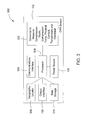
FIGURE 3 is a block diagram of a CPR sensor in accordance with a second embodiment of the present invention; -
FIGURE 4 is an exploded view of a CPR sensor in accordance with a third embodiment of the present invention; -
FIGURE 5 is a sectional view of the CPR sensor in accordance with the third embodiment of the present invention; -
FIGURES 6A and 6B are top and bottom views respectively of a CPR sensor in accordance with a fourth embodiment of the present invention; -
FIGURE 7 illustrates an optimal position of a hand in relation to a CPR sensor in accordance with the fourth embodiment of the present invention; -
FIGURE 8 illustrates an optimal position of a hand and a CPR sensor in relation to a patient's body in accordance with the fourth embodiment of the present invention; -
FIGURE 9 is a block diagram of a system to communicate with a CPR sensor in accordance with one embodiment of the present invention; and -
FIGURE 10 is a flow chart of a manufacturing process to make a CPR sensor in accordance with the present invention. - While the making and using of various embodiments of the present invention are discussed in detail below, it should be appreciated that the present invention provides many applicable inventive concepts that can be embodied in a wide variety of specific contexts. The specific embodiments discussed herein are merely illustrative of specific ways to make and use the invention and do not delimit the scope of the invention. The discussion herein relates primarily to CPR sensors, but it will be understood that the concepts of the present invention are applicable to any thin form pressure, force, frequency and/or acceleration sensors.
- The new Guidelines for First Aid co-developed by the American Red Cross and American Heart Association as well as the American Heart Association's CPR Guidelines were released on Nov. 28, 2005. According to these guidelines, the chest needs to be pushed down at least 4 centimeters and released between the nipples 30 consecutive times at the rate of 100 times per minute followed by two breaths. This procedure is to be repeated. The present invention measures the applied pressure and the acceleration by which the CPR is administered on the chest, from which the chest depression is to be calculated. In addition, the number of depressions and release actions is to be counted. If the procedure adheres to the specifications, a visual and/or audio feedback is provided to the responder. The procedure and the effectiveness can also be recorded on the strip to be downloaded and analyzed at a later date.
- The CPR sensor is a low cost, very compact assembly of individual force and/or pressure, acceleration sensors, powering source (battery or energy harvesting with conditioning and storage electronics), biasing circuitry, read-out circuitry and necessary electrical connections. Individual sensors are fabricated on traditional non-flexible substrates (silicon). These individual sensors are then placed on a flexible printed circuit or a rigid card. The CPR sensor can be incorporated into portable emergency defibrillator equipment or can be used stand-alone. The market for the CPR sensor is every home or even having every adult person carrying a strip in his/her pocket for emergencies in various forms as part of a "Smart Card", a credit card or another form. Because of its revolutionary small size and low cost, it can be manufactured as part of a wallet, a pocket or part of any clothing. For public places like schools, airports, work-places, disposable versions can be stored with the emergency equipment. Flexible, disposable versions can be incorporated into public phones, cell phones or land-line home phones as removable strips when needed. CPR sensor can be incorporated into CPR training classes where manikins are used. In addition, it can be utilized in education and training classes for health professionals.
- The present invention provides a CPR sensor that is compact and thin so as to be readily available and easily portable, self-contained and wireless, self-powered, semi-flexible, simple and easy to use within minimal instruction and provides real-time feedback to the CPR resuscitator or provider. Moreover, the present invention will directly impact the effectiveness of CPR administered by laypersons and professionals, strengthening the second link - fast and effective CPR - in the Chain of Survival, and thus potentially reduce the fatality risk in emergency situations. The CPR sensor, which can be easily carried in a wallet or other personal belonging or clothing so that it can be located quickly during an emergency, informs the CPR provider on the characteristics of the chest compression as they are being performed. In addition, the CPR sensor permits swift and correct positioning of the helper's hands during CPR, and provides clear and concise feedback.
- Now referring to
FIGURE 1 , a block diagram of aCPR sensor 100 in accordance with first embodiment of the present invention is shown. TheCPR sensor 100 includes a thin and substantially flatflexible substrate 102 having one ormore sensor arrays 104, apower source 106 and anoutput interface 108, all of which are disposed on the substantially flatflexible substrate 102. Thesubstrate 102 can be any shape (e.g., rectangular, circular, a polygon, an irregular shape that is decorative) and made from a polymer, metal film or other suitable material. Note that thesubstrate 102 can be rigid or semi-flexible instead of flexible. If thesubstrate 102 is flexible or semi-flexible, it should be able to be stretched, wrinkled or flexed without degradation of thesensors 104. The one ormore sensor arrays 104 measure one or more compression characteristics (e.g., depth, force, frequency, acceleration, etc.). Thesensor array 104 andoutput interface 108 are connected to thepower source 106. - A processor or analog circuit or logic circuit within or external to the
sensor arrays 104 and/oroutput interface 108 determines whether one or more operational parameters are within one or more guidelines in order to provide feedback to the CPR provider indicating whether the operational parameters are within the guidelines via theoutput interface 108. The one or more operational parameters may include an applied pressure, an acceleration, a chest depression, a number of depressions, a number of release actions, a cardiac electrical activity or a combination thereof. The one ormore sensors 104 may also detect a heart beat, pulse or cardiac electrical activity of a CPR recipient, a physical contact with a CPR recipient, a physical contact with a CPR provider or a temperature of the CPR recipient. The CPR recipient can be a human, an animal or a manikin. The CPR provider can be a human or a machine. Theoutput interface 108 can be a visual display (e.g., light emitting diodes, liquid crystal displays or other visual display known to those skilled in the art), a speaker, a multi-tone generator, a communications interface or a combination thereof. The visual display can be a set of light emitting diodes that provide a feedback to the CPR provider, a status of the CPR sensor, a status of the CPR recipient or a combination thereof. - The
power source 106 can be a battery, a solar panel, a layer of piezoelectric film or any type of energy harvesting technology for voltage generation during compressions, a cardiac electrical voltage generator or a combination thereof. Note that thebattery 106 can be disposed on theflexible substrate 102 such that it is replaceable or rechargeable. Thepower source 106 can also be a combination of a battery along with one of the voltage generators connected to a power controller to manage power consumption and storage in the battery and the layer of piezoelectric film or other energy harvesting methods for voltage generation during compressions. - A protective layer (not shown) may cover the
sensor array 104 andpower source 108. A window or clear protective layer can be used to protect theoutput interface 108, yet still allow theoutput interface 108 to provide data, signals, indications and visual and/or audio signals. Alternatively, a protective covering can be used to encapsulate thedevice 100. - The
CPR sensor 100 can be integrated in or attached to a manikin, a device, a business card, a credit card, a debit card, a membership card, a driver's license, an identification card, a wallet, a clothing or other thin portable user device. The device can be a defibrillator, a cellular phone, a mobile communications device, a personal data assistant, an audio and/or video playback device or other device likely to be carried by a person. TheCPR sensor 100 can also be disposable for use by medical service providers in cases where they are not allowed to reuse such devices. TheCPR sensor 100 may also include an adhesive layer dispose on a back exterior surface of theCPR sensor 100 and a sheet of removable protective material covering the adhesive layer so that theCPR sensor 100 will temporarily remain in place on the patient or manikin. - Referring now to
FIGURE 2 , a block diagram of asensor array 104 to measure compression depth, compression force, compression frequency and/or compression acceleration in accordance with one embodiment of the present invention is shown. Thesensor array 104 can include one ormore accelerometers 200 and one ormore pressure sensors 202 positioned around theaccelerometer 200. Other arrangement and numbers of individual sensors can be used. - Now referring to
FIGURE 3 , a block diagram of aCPR sensor 300 in accordance with a second embodiment of the present invention is shown. TheCPR sensor 300 includes a thin and substantially flatflexible substrate 102 having one ormore sensor arrays 302, a processor oranalog circuit 304, apower source 106, acommunications interface 306, ageographic locator 308, anoutput interface 108 and adata storage 310, all of which are disposed on the substantially flatflexible substrate 102. Thesubstrate 102 can be any shape (e.g., rectangular, circular, a polygon, an irregular shape that is decorative) and made from a polymer, metal film or other suitable material. Note that thesubstrate 102 can be rigid or semi-flexible instead of flexible. If thesubstrate 102 is flexible or semi-flexible, it should be able to be stretched, wrinkled or flexed without degradation of thesensors 302. The geographic locator can be a GPS receiver, wireless communications device or other wireless location device. A protective layer (not shown) covers thesensor array 302, processor oranalog circuit 304,power source 106,communications interface 306,geographic locator 308,output interface 108 anddata storage 310. A window or clear protective layer can be used to protect theoutput interface 108 and communications interface 306 (if necessary), yet still allow theoutput interface 108 and/orcommunications interface 306 to operate properly and as intended. Alternatively, a protective covering can be used to encapsulate thedevice 300. The one ormore sensor arrays 302 measure one or more compression characteristics (e.g., depth, force, frequency, acceleration, etc.) and one or more operational parameters (e.g., physical contact with a CPR recipient, physical contact with a CPR provider, temperature of the CPR recipient, heartbeat of the CPR recipient, pulse of the CPR recipient, cardiac electrical activity of the CPR recipient, etc.). The processor oranalog circuit 304 is connected to thesensor array 302,power source 106,communications interface 306,geographic locator 308,output interface 108 anddata storage 310. Thesensor array 302,communications interface 306,geographic locator 308,output interface 108 anddata storage 310 may also be connected to thepower source 106. - The processor or
analog circuit 304 determines whether one or more operational parameters are within one or more guidelines in order to provide feedback to the CPR provider indicating whether the operational parameters are within the guidelines via theoutput interface 108. The one or more operational parameters may include an applied pressure, acceleration, a chest depression, a number of depressions, a number of release actions, cardiac electrical activity or a combination thereof. The CPR recipient can be a human, an animal or a manikin. The CPR provider can be a human or a machine. Theoutput interface 108 can be a visual display (e.g., light emitting diodes, liquid crystal displays or other visual display known to those skilled in the art), a speaker, a multi-tone generator, a communications interface or a combination thereof. The visual display can be a set of light emitting diodes that provide a feedback to the CPR provider, a status of the CPR sensor, a status of the CPR recipient or a combination thereof. The visual display can also be a LCD/CRT-like display that provides interactive wireless communication between the provider and other support personnel. - The
communications interface 306 can be an optical communications interface, an infrared communications interface, a wireless communications transceiver, a physical communications port or a combination thereof. The wireless transceiver can be a cellular phone, Internet communication, personal data assistant (PDA), an active radio frequency identification tag, a passive radio frequency identification tag, etc.. The geographic locator 308 (e.g., GPS receiver, wireless communications device, etc.) can be used to determine a location of theCPR sensor 300. The processor oranalog circuit 304 can periodically transmits a status of theCPR sensor 300, location of theCPR sensor 300, diagnostic information, a status of the CPR recipient or a combination thereof to a medical service provider via thecommunications interface 306. The processor oranalog circuit 304 can receive instructions from medical service providers via thecommunications interface 306. Thedata storage 310 can be used to store the one or more parameters, the feedback, a status of the CPR sensor, diagnostic information or a combination thereof. Thedata storage 310 can be a RFID tag, a magnetic strip, a memory or a combination thereof. - The
power source 106 can be a battery, a solar panel, a layer of piezoelectric film for voltage generation during compressions, an electromagnetic voltage generator or a combination thereof. Note that thebattery 106 can be disposed on theflexible substrate 102 such that it is replaceable or rechargeable. Thepower source 106 can also be a combination of a battery along with one of the voltage generators connected to a power controller to manage power consumption and storage in the battery and the layer of piezoelectric film or other energy harvesting methods for voltage generation during compressions. - The
CPR sensor 300 can be integrated in or attached to a manikin, a device, a business card, a credit card, a debit card, a membership card, a driver's license, an identification card, a wallet, a clothing or other thin portable user device. The device can be a defibrillator, a phone, a mobile communications device or a personal data assistant. TheCPR sensor 300 can also be disposable for use by medical service providers in cases where they are not allowed to reuse such devices. TheCPR sensor 300 may also include an adhesive layer disposed on a back exterior surface of theCPR sensor 300 and a sheet of removable protective material covering the adhesive layer so that theCPR sensor 300 will temporarily remain in place on the patient or manikin. - Referring now to
FIGURE 4 , an exploded view of aCPR sensor 400 in accordance with a third embodiment of the present invention is shown. TheCPR sensor 400 includes an upperprotective layer 402, a lowerprotective layer 404, a thin and substantially flatflexible substrate 406 and an energy producing layer 408 (e.g., a layer of piezoelectric film or other means for energy harvesting during compressions). Thesubstrate 406 can be any shape (e.g., rectangular, circular, a polygon, an irregular shape that is decorative) and made from a polymer, metal film or other suitable material. The thin and substantially flatflexible substrate 406 and anenergy producing layer 408 are both disposed between the upperprotective layer 402 and the lowerprotective layer 404. The upperprotective layer 402 and lowerprotective layer 404 are semi rigid plastic films, but other materials can also be used. Upper protective layer can also be made of a transparent or semi-transparent material. If the upperprotective layer 402 is not transparent, upperprotective layer 402 will include an opening orwindow 424 oriented above theoutput interface 418. Theenergy producing layer 408 can be a piezoelectric film or other means which generates a voltage in response to applied mechanical stress. During use,layer 408 is compressed and will start generating a voltage which will be applied to collecting means 416 inlayer 406. The first compressions will not lead to a sufficiently high voltage to generate a visible signal, but after a short period of time the voltage will reach a sufficient level and feedback will be provided. - In addition, one or more sensor arrays (six
force sensors 410 and one compression depth sensor 412), asignal processor 414, a power source 416 (energy collector and producer means) and an output interface 418 (e.g., light emitting diodes, liquid crystal displays or other visual display known to those skilled in the art) are disposed on or attached to theflexible substrate 406. The one ormore sensor arrays signal processor 414 is connected to thesensor array output interface 418 andpower source 416. Thesignal processor 414 compares the measured signals with threshold values and provides a feedback signal according to the results of the comparison to theoutput interface 418. This signal can be in the form of a series of lights corresponding to different compression depths and/or compression forces. Theflexible substrate 406 also includesvarious leads 420 for connecting to other layers and components, andconnections 422 to theenergy producing layer 408. Theoutput interface 418 displays different variables related to performance of CPR, such as compression depth, force, rate, etc. - Now referring to
FIGURE 5 , a sectional view of theCPR sensor 400 in accordance with the third embodiment of the present invention is shown. The substantially flat body of theCPR sensor 400 has four layers including a thin and substantially flatflexible substrate 406 and anenergy producing layer 408 disposed between the upperprotective layer 402 and the lowerprotective layer 404. Thesubstrate 406 can be any shape (e.g., rectangular, circular, a polygon, an irregular shape that is decorative) and made from a polymer, metal film or other suitable material. Theflat body 400 in this embodiment has an approximate thickness of 1.25mm. Note that it is possible to combine themiddle layers - Referring now to
FIGURES 6A and 6B , top and bottom views respectively of aCPR sensor 600 in accordance with a fourth embodiment of the present invention are shown. In this embodiment, thefeedback device 600 is shaped as a card, such as a credit card, debit card, membership card, driving license or identification card, both in area and thickness whilst retaining the normal functions of such cards.FIGURE 6A illustrates the opening orwindow 408 for the output interface and the possibility of providing the card with writteninformation 602. As a supplementary feature thefeedback device 600 can be equipped with amagnetic strip 604, which permits storage and exchange of information with suitable devices, and other information bearing devices common to traditional credit cards so that it can also function as a credit card. Note thatsignal processor 414 can be the processing unit in a conventional smart card. - Now referring to
FIGURE 7 , an optimal position of ahand 702 in relation to aCPR sensor 600 in accordance with the fourth embodiment of the present invention is shown.Hand 702 is positioned with its middle line across theedge 704 of thedevice 600. Information on correct placement of the hand on the device can be available as text and/or drawings on thedevice 600. - Referring now to
FIGURE 8 , an optimal position of ahand 702 and aCPR sensor 600 in relation to a patient'sbody 800 in accordance with the fourth embodiment of the present invention is shown. During use thedevice 600 will be placed on the patient's chest (with its edge on line A (nipple line) to mark the correct positioning ofhand 702 on the patient's body 800) and chest compressions will be performed on the chest through thefeedback device 600. Information on correct placement of thedevice 600 on the patient's chest can also be available as text and/or drawings on thedevice 600. The invention provides a simple way of ensuring correct positioning of thehand 702 when performing CPR. At the same time thedisplay device 600 gives feedback on other parameters related to CPR. - Now referring to
FIGURE 9 , a block diagram of asystem 900 to communicate with aCPR sensor 300 in accordance with one embodiment of the present invention is shown.CPR sensor 300 receives signals fromGPS satellites 902 via an internal GPS receiver (geographic locator) so that the position of theCPR sensor 300 can be determined. This information along with other desirable information regarding the status of theCPR sensor 300 and the CPR patient (recipient) can be transmitted (continuously or periodically) to a remotemedical service provider 904 via acommunications network 906 using an internal communications interface. Themedical service provider 904 can be a doctor, 911 operator, emergency medical technician, ambulance, hospital, clinic, etc. Thecommunications network 906 can be any type of wireless communications network or combination of wireless and landline network. - Referring now to
FIGURE 10 , a flow chart of amanufacturing process 1000 to make a CPR sensor in accordance with the present invention is shown. Themethod 1000 for manufacturing a CPR sensor includes the following steps: passivate asilicon wafer 1002; add a polyimide layer to thewafer 1004; create one or more sensor arrays using aMEMS process 1006 wherein the sensor array(s) measure compression depth, compression force, compression frequency and/or compression acceleration; dice the wafer to extract the individual dies/sensors 1008; print a circuit on aflexible substrate 1010; apply a paste or epoxy to the flexible substrate to receive and secure the individual dies/sensors 1012; place the individual dies/sensors on theflexible substrate 1014; place the flexible substrate on a lower protective layer containing electrical interconnects and an output interface, a processor or analog circuit and apower source 1016; secure the flexible substrate to the lowerprotective layer 1018; place and secure a upper protective layer to the flexible substrate and the lower protective layer to compete assembly of theCPR sensor 1020; and test theCPR sensor 1022. -
- 1. "Uncooled Infrared Microbolometers on a Flexible Substrate," A. Yaradanakul, D. P. Butler, and Z. Celik-Butler, IEEE Transactions on Electron Devices, vol. 49, pp. 930 - 933, 2002.
- 2. "Microbolometers on a Flexible Substrate for Infrared Detection," A. Yildiz, Z. Celik-Butler, D. P. Butler, IEEE Sensors Journal, vol. 4, pp. 112-117 (2004).
- 3. "Flexible Microbolometers Promise Smart Fabrics with Imbedded Sensors," A. Mahmood, D. P. Butler and Z. Celik-Butler, Laser Focus World, pp. 99-103 (April 2004).
- 4. "Micromachined Infrared Bolometers on Flexible Polyimide Substrates," S. A. Dayeh, D. P. Butler and Z. Celik-Butler, Sensors and Actuators vol. A118, pp. 49-56 (2005).
- 5. "Micromachined Integrated Pressure-Thermal Sensors on Flexible Substrates," V. Shamanna, S. Das, Z. Celik-Butler, D. P. Butler, and K. L. Lawrence, Journal of Micromechanics and Microengineering vol. 16, 1984-1992 (2006).
- 6. "Micromachined Bolometers on Polyimide," A. Mahmood, Z. Celik-Butler, and D. Butler, "Sensors and Actuators A, vol. 132, pp. 452-459 (2006).
- 7. "Flexible Sensors: a Review," Z. Celik-Butler and D. P. Butler, J. Nanoelectronics and Optoelectronics, vol. 1, pp. 194-202 (2006).
- 8. "Smart Skin," Mid-Cities Technical Club Meeting, Arlington, TX (March 3, 2004).
- 9. "Smart Skin: Multifunctional Sensory Arrays on Flexible Substrates," Strategic Partnership for Research in Nanotechnology (SPRING) Workshop 11, University of Texas at Dallas, (November 12 2004).
- 10. "Smart Skin: Multisensory Arrays on Flexible Substrates," Freescale Semiconductor Co., Tempe, AZ (January 13, 2006).
- 11. "Self Packaged Flexible Electronics, IEEE-EDIS Distinguished Lecture, Tempe AZ (January 13, 2006).
- 12. "Nano-Bio Interface," BIODFW Regional Alliance, Southwestern Medical Center, Dallas, TX (April 20, 2006).
- 13. "Self-Packaged Flexible Electronics," NanoTX, Dallas Convention Center, Dallas TX (September 28, 2006).
- It will be understood by those of skill in the art that information and signals may be represented using any of a variety of different technologies and techniques (e.g., data, instructions, commands, information, signals, bits, symbols, and chips may be represented by voltages, currents, electromagnetic waves, magnetic fields or particles, optical fields or particles, or any combination thereof). Likewise, the various illustrative logical blocks, modules, circuits, and algorithm steps described herein may be implemented as electronic hardware, computer software, or combinations of both, depending on the application and functionality. Moreover, the various logical blocks, modules, and circuits described herein may be implemented or performed with a general purpose processor (e.g., microprocessor, conventional processor, controller, microcontroller, state machine or combination of computing devices), a digital signal processor ("DSP"), an application specific integrated circuit ("ASIC"), a field programmable gate array ("FPGA") or other programmable logic device, discrete gate or transistor logic, discrete hardware components, or any combination thereof designed to perform the functions described herein. Similarly, steps of a method or process described herein may be embodied directly in hardware including a purely analog circuit, in a software module executed by a processor, or in a combination of the two. A software module may reside in RAM memory, flash memory, ROM memory, EPROM memory, EEPROM memory, registers, hard disk, a removable disk, a CD-ROM, or any other form of storage medium known in the art. Although preferred embodiments of the present invention have been described in detail, it will be understood by those skilled in the art that various modifications can be made therein without departing from the spirit and scope of the invention as set forth in the appended claims.
Claims (30)
- A cardiopulmonary resuscitation (CPR) sensor comprising:a thin and substantially flat substrate;one or more sensor arrays disposed on the substrate that measure one or more compression characteristics;an output interface disposed on the substrate;a processor or an analog circuit disposed on the substrate and connected to the one or more sensor arrays and the output interface; anda power source disposed on the substrate and connected to the one or more sensor arrays, the output interface, and the processor or the analog circuit.
- The CPR sensor as recited in claim 1, wherein the substrate is flexible.
- The CPR sensor as recited in claim 1, wherein the substrate is rigid or semi-flexible.
- The CPR sensor as recited in one of the claims 1 to 3, wherein:the substrate comprises a polymer or a metal film; andthe one or more compression characteristics comprise depth, force, frequency or acceleration.
- The CPR sensor as recited in one of the claims 1 to 4, further comprising a protective layer covering the sensor array(s), the processor or the analog circuit, and the power source.
- The CPR sensor as recited in one of the claims 1 to 4, further comprising:an upper protective layer;a lower protective layer; wherein the substantially flat substrate being disposed between the upper protective layer and the lower protective layer.
- The CPR sensor as recited in claim 6, wherein the upper protective layer and the lower protective layer encapsulate the substrate.
- The CPR sensor as recited in claim 6, further comprising an energy producing layer disposed between the lower protective layer and the substrate.
- The CPR sensor as recited in one of the claims 1 to 8, wherein the sensor array(s) comprise:one or more accelerometers; andone or more pressure sensors positioned around the accelerometer (s) .
- The CPR sensor as recited in one of the claims 1 to 9, wherein:the processor or the analog circuit determines whether one or more operational parameters are within one or more guidelines and provides a feedback regarding whether the operational parameters are within the guidelines via the output interface; andthe one or more operational parameters comprise an applied pressure, an acceleration, a chest depression, a number of depressions, a number of release actions, and cardiac electrical activity or a combination thereof.
- The CPR sensor as recited in claim 10, further comprising a data storage connected to the processor or the analog circuit that stores the one or more parameters, the feedback, a status of the CPR sensor, diagnostic information or a combination thereof.
- The CPR sensor as recited in claim 11, wherein the data storage comprises a RFID tag, a magnetic strip, a memory or a combination thereof.
- The CPR sensor as recited in one of the claims 1 to 12, wherein the sensor array(s) further measure one or more operational parameters, wherein the one or more operational parameters comprise a physical contact with a CPR recipient, a physical contact with a CPR provider, a temperature of the CPR recipient, a heartbeat of the CPR recipient, a pulse of the CPR recipient or a cardiac electrical activity of the CPR recipient.
- The CPR sensor as recited in one of the claims 1 to 13, wherein the output interface comprises a visual display, a speaker, a multi-tone generator, a communications interface or a combination thereof.
- The CPR sensor as recited in claim 14, wherein the visual display comprises a set of light emitting diodes, a liquid crystal display or combination thereof that provide a feedback to the CPR provider, a status of the CPR sensor, a status of the CPR recipient or a combination thereof.
- The CPR sensor as recited in claim 14, wherein the communications interface comprises an optical communications interface, an infrared communications interface, a wireless communications transceiver, a physical communications port or a combination thereof.
- The CPR sensor as recited in claim 16, wherein the wireless transceiver comprises an active radio frequency identification tag, a passive radio frequency identification tag, a cellular phone, an Internet connection or a personal data assistant.
- The CPR sensor as recited in one of the claims 1 to 17, further comprising:a geographic locator that is disposed on the substrate and connected to the processor or the analog circuit; anda communications interface disposed on the substrate, connected to the processor or the analog circuit, wherein the processor or the analog circuit periodically transmits a status of the CPR sensor, a location of the CPR sensor as determined by the geographic locator, diagnostic information, a status of the CPR recipient or a combination thereof to a medical service provider via the communications interface.
- The CPR sensor as recited in claim 2, wherein the substrate can be stretched, wrinkled or flexed without degradation of the sensors.
- The CPR sensor as recited in one of the claims 1 to 19, wherein the CPR sensor is integrated in or attached to a manikin, a CPR recipient, a device, a business card, a credit card, a debit card, a membership card, a driver's license, an identification card, a wallet, a clothing or other thin portable user device.
- The CPR sensor as recited in claim 20, wherein the device comprises a defibrillator, a phone, a mobile communications device, a cellular phone, an audio and/or video device or a personal data assistant.
- The CPR sensor as recited in one of the claims 1 to 21, wherein the CPR sensor is shaped, both in area and thickness, like a credit card.
- The CPR sensor as recited in one of the claims 1 to 22, wherein the power source comprises a battery, a solar panel, a layer of piezoelectric film for voltage generation during compressions, an electromagnetic voltage generator, an energy harvesting device or a combination thereof.
- The CPR sensor as recited in claim 23, wherein the battery is replaceable or rechargeable.
- The CPR sensor as recited in one of the claims 1 to 24, wherein the power source comprises:a battery;layer of piezoelectric film or other energy harvesting methods for voltage generation during compressions; anda power controller to manage power consumption and storage in the battery and the layer of piezoelectric film for voltage generation during compressions.
- The CPR sensor as recited in one of the claims 1 to 25, wherein the CPR sensor is disposable.
- The CPR sensor as recited in one of the claims 1 to 26, further comprising:an adhesive layer dispose on a back exterior surface of the CPR sensor; anda sheet of removable protective material covering the adhesive layer.
- The CPR sensor as recited in one of the claims 1 to 27, further comprising a magnetic strip, a RFID tag, a wireless communications device or other information bearing device disposed on the exterior or interior of the CPR sensor.
- A method or manufacturing a cardiopulmonary resuscitation (CPR) sensor comprising the steps of:passivating a silicon wafer;adding a polyimide layer to the wafer;creating one or more sensor arrays using a MEMS process wherein the sensor array(s) measure compression depth and compression force;dicing the wafer to extract the individual dies/sensorsprinting a circuit on a substrate;applying a paste or epoxy to the substrate to receive and secure the individual dies/sensors;placing the individual dies/sensors on the substrate;placing the substrate on a lower protective layer containing electrical interconnects and an output interface, a processor or an analog circuit, and a power source;securing the substrate to the lower protective layer;placing and securing a upper protective layer to the substrate and the lower protective layer to compete assembly of the CPR sensor.
- The method as recited in claim 29, further comprising the step of testing the CPR sensor.
Applications Claiming Priority (1)
| Application Number | Priority Date | Filing Date | Title |
|---|---|---|---|
| US11/764,174 US8034006B2 (en) | 2007-06-15 | 2007-06-15 | Cardiopulmonary resuscitation sensor |
Publications (1)
| Publication Number | Publication Date |
|---|---|
| EP2002817A1 true EP2002817A1 (en) | 2008-12-17 |
Family
ID=39707202
Family Applications (1)
| Application Number | Title | Priority Date | Filing Date |
|---|---|---|---|
| EP08450087A Ceased EP2002817A1 (en) | 2007-06-15 | 2008-06-03 | Cardiopulmonary resuscitation sensor |
Country Status (3)
| Country | Link |
|---|---|
| US (1) | US8034006B2 (en) |
| EP (1) | EP2002817A1 (en) |
| JP (2) | JP5340579B2 (en) |
Cited By (4)
| Publication number | Priority date | Publication date | Assignee | Title |
|---|---|---|---|---|
| WO2012035129A3 (en) * | 2010-09-17 | 2012-05-10 | Laerdal Medical As | Manikin with cpr hand position detection |
| CN102341085B (en) * | 2009-03-06 | 2014-02-12 | 阿特雷奥医疗公司 | Measurement of compression parameter for CPR on surface |
| TWI715352B (en) * | 2018-12-13 | 2021-01-01 | 國立臺灣大學醫學院附設醫院 | Guide device for portable cardiopulmonary resuscitation |
| CN115472049A (en) * | 2022-08-09 | 2022-12-13 | 惠州学院 | An amphibious rope-throwing training device for water rescue |
Families Citing this family (85)
| Publication number | Priority date | Publication date | Assignee | Title |
|---|---|---|---|---|
| US9028259B2 (en) | 2007-01-16 | 2015-05-12 | Physio-Control, Inc. | Wearable CPR assist, training and testing device |
| US8994528B2 (en) * | 2007-06-15 | 2015-03-31 | Board Of Regents, The University Of Texas System | Thin flexible sensor |
| NL2000835C2 (en) * | 2007-08-29 | 2009-03-03 | Xsens Technologies Bv | Device and method for measuring the dynamic interaction between bodies. |
| US20100324437A1 (en) * | 2007-09-12 | 2010-12-23 | Freeman Jenny E | Device and method for assessing physiological parameters |
| WO2010042594A1 (en) * | 2008-10-08 | 2010-04-15 | Infinite Power Solutions, Inc. | Environmentally-powered wireless sensor module |
| KR101071432B1 (en) | 2009-01-29 | 2011-10-10 | 연세대학교 산학협력단 | Apparatus for measuring compression depth in cardiopulmonary resuscitation |
| US8641617B2 (en) | 2009-04-02 | 2014-02-04 | Indian Institute Of Science | In-place display on sensory data |
| US8734161B1 (en) * | 2009-07-17 | 2014-05-27 | Physio-Control, Inc. | CPR training system using consumer electronic device |
| CA2780769A1 (en) | 2009-11-13 | 2011-05-19 | Zoll Medical Corporation | Cpr competition system |
| US8325032B2 (en) * | 2009-11-29 | 2012-12-04 | Yang Pan | Miniature life-saving device |
| US9351654B2 (en) | 2010-06-08 | 2016-05-31 | Alivecor, Inc. | Two electrode apparatus and methods for twelve lead ECG |
| US8509882B2 (en) | 2010-06-08 | 2013-08-13 | Alivecor, Inc. | Heart monitoring system usable with a smartphone or computer |
| US9198826B2 (en) | 2010-07-13 | 2015-12-01 | Physio-Control, Inc. | CPR chest compression machine stopping to detect patient recovery |
| US10702166B1 (en) | 2010-08-13 | 2020-07-07 | Respiratory Motion, Inc. | Devices and methods for respiratory variation monitoring by measurement of respiratory volumes, motion and variability |
| US11723542B2 (en) | 2010-08-13 | 2023-08-15 | Respiratory Motion, Inc. | Advanced respiratory monitor and system |
| ES2660013T3 (en) | 2010-08-13 | 2018-03-20 | Respiratory Motion, Inc. | Devices and methods for monitoring respiratory variation by measuring respiratory volumes, movement and variability |
| NO20101497A1 (en) | 2010-10-26 | 2012-04-27 | Laerdal Medical As | CPR monitoring system |
| WO2012065104A2 (en) * | 2010-11-12 | 2012-05-18 | Zoll Medical Corporation | Hand mounted cpr chest compression monitor |
| US8738129B2 (en) * | 2010-11-12 | 2014-05-27 | Zoll Medical Corporation | Real-time evaluation of CPR performance |
| WO2013058818A2 (en) * | 2011-04-08 | 2013-04-25 | Zoll Medical Corporation | Coordinated resuscitation perfusion support |
| US10238574B2 (en) | 2011-04-08 | 2019-03-26 | Zoll Medical Corporation | System for assisting rescuers in performing cardio-pulmonary resuscitation (CPR) on a patient |
| MX365902B (en) * | 2011-07-20 | 2019-06-19 | Respiratory Motion Inc | IMPEDANCE MEASUREMENT DEVICES AND METHODS FOR EMERGENCY CARDIOVASCULAR CARE. |
| WO2013032597A1 (en) * | 2011-08-26 | 2013-03-07 | Zoll Medical Corporation | Defibrillator including light sensor |
| BR112014014645A2 (en) * | 2011-12-21 | 2017-06-13 | Koninklijke Philips Nv | cardiopulmonary resuscitation support device, and method for providing assistance in administering cardiopulmonary resuscitation to a patient |
| WO2013120720A1 (en) | 2012-02-17 | 2013-08-22 | Laerdal Medical As | System and method for maintenance of competence |
| WO2013120717A1 (en) | 2012-02-17 | 2013-08-22 | Laerdal Medical As | Device to record competence |
| US20130280686A1 (en) | 2012-04-19 | 2013-10-24 | Martin Hetland | Medical Procedure Training System |
| US9886873B2 (en) * | 2012-04-19 | 2018-02-06 | Laerdal Medical As | Method and apparatus for developing medical training scenarios |
| US8942800B2 (en) | 2012-04-20 | 2015-01-27 | Cardiac Science Corporation | Corrective prompting system for appropriate chest compressions |
| US12343130B2 (en) | 2012-09-07 | 2025-07-01 | Respiratory Motion, Inc. | Spacing of electrodes for bioimpedance measurements |
| MX353153B (en) | 2012-09-07 | 2017-12-20 | Respiratory Motion Inc | Electrode padset. |
| US9254095B2 (en) | 2012-11-08 | 2016-02-09 | Alivecor | Electrocardiogram signal detection |
| WO2014107700A1 (en) | 2013-01-07 | 2014-07-10 | Alivecor, Inc. | Methods and systems for electrode placement |
| US9489870B2 (en) * | 2013-01-26 | 2016-11-08 | Gaumard Scientific Company, Inc. | Medical simulators with energy harvesting power supplies |
| US20140257150A1 (en) | 2013-03-07 | 2014-09-11 | Zoll Medical Corporation | Providing Feedback for CPR Treatment |
| US9254092B2 (en) | 2013-03-15 | 2016-02-09 | Alivecor, Inc. | Systems and methods for processing and analyzing medical data |
| AU2014235437A1 (en) * | 2013-03-15 | 2015-10-29 | Ashi Holding Company | Online CPR training and certification |
| JP6194550B2 (en) * | 2013-04-26 | 2017-09-13 | 学校法人自治医科大学 | Procedure simulator |
| US9247911B2 (en) | 2013-07-10 | 2016-02-02 | Alivecor, Inc. | Devices and methods for real-time denoising of electrocardiograms |
| US20150088016A1 (en) | 2013-09-25 | 2015-03-26 | Zoll Medical Corporation | Mobile Device Control |
| KR101780214B1 (en) * | 2013-11-29 | 2017-10-10 | (주)나눔테크 | Emergency rescue system using the automated external defibrillator |
| EP3079571A4 (en) | 2013-12-12 | 2017-08-02 | Alivecor, Inc. | Methods and systems for arrhythmia tracking and scoring |
| DE102013022397A1 (en) | 2013-12-19 | 2016-07-07 | Metrax Gmbh | Device for assisting a first-aider in cardiac massage |
| US9576503B2 (en) | 2013-12-27 | 2017-02-21 | Seattle Children's Hospital | Simulation cart |
| DE102014102590B4 (en) * | 2014-01-22 | 2022-12-22 | Michael Müller | System to assist a lay rescuer in resuscitation of a patient in cardiac arrest |
| EP3114672B1 (en) | 2014-03-06 | 2020-06-24 | Respiratory Motion, Inc. | Methods and devices for displaying trend and variability in a physiological dataset |
| US10596064B2 (en) | 2014-03-18 | 2020-03-24 | Zoll Medical Corporation | CPR chest compression system with tonometric input and feedback |
| DE102014104673A1 (en) * | 2014-04-02 | 2015-10-08 | Infineon Technologies Ag | Process support system and method for supporting a process |
| US11141599B2 (en) | 2014-04-04 | 2021-10-12 | Los Angeles Biomedical Research Institute At Harbor-Ucla Medical Center | Systems, apparatus, and methods for documenting code blue scenarios |
| US9743882B2 (en) * | 2014-04-04 | 2017-08-29 | Los Angeles Biomedical Research Institute At Harbor-Ucla Medical Center | Systems, apparatus, and methods for documenting code blue scenarios |
| US20150351647A1 (en) * | 2014-05-01 | 2015-12-10 | University Of North Texas | Effective cpr procedure with real time evaluation and feedback using smartphones |
| DE102014108197A1 (en) | 2014-06-11 | 2015-12-17 | Metrax Gmbh | A device for assisting rescue personnel in performing cardiopulmonary resuscitation |
| AT516135B1 (en) * | 2014-08-08 | 2016-08-15 | Sense Product Gmbh | Device for posturography |
| KR101671274B1 (en) * | 2014-10-23 | 2016-11-01 | 오유진 | Guide-patch for hands-only cardiopulmonary resuscitation |
| CN107427627A (en) | 2014-11-04 | 2017-12-01 | 呼吸运动公司 | The automation IV administrations and the activation of IV pipe clamps of respiration parameter guiding |
| KR101628073B1 (en) * | 2014-11-04 | 2016-06-08 | 김태완 | Cardiopulmonary resuscitation plate for a first-aid treatment |
| EP4101501B1 (en) | 2015-03-27 | 2025-10-29 | ZOLL Medical Corporation | Ecg and defibrillator electrode detection and tracking system |
| DE102015111346A1 (en) | 2015-05-06 | 2016-11-10 | Michael Müller | Device configuration to assist in cardiopulmonary resuscitation |
| CN107847154B (en) | 2015-05-13 | 2021-07-16 | 阿利弗克公司 | Inconsistency monitoring |
| RU2017146761A (en) | 2015-05-28 | 2019-06-28 | Конинклейке Филипс Н.В. | METHOD, COMPUTER SOFTWARE PRODUCT AND SYSTEM OF ENSURING THE ISSUE OF GUIDELINES ON CARDIAC AND PULMONARY REANIMATION |
| WO2017056042A1 (en) | 2015-10-01 | 2017-04-06 | Koninklijke Philips N.V. | Cpr assistance system |
| WO2017106500A1 (en) | 2015-12-15 | 2017-06-22 | Respiratory Motion, Inc. | Evaluation of respiratory volume monitoring to detect respiratory compromise before pulse oximetry and eliminate false desaturation alarms |
| JP6746347B2 (en) * | 2016-03-30 | 2020-08-26 | 住友理工株式会社 | Cardiopulmonary resuscitation assist device |
| US10561575B2 (en) * | 2016-03-31 | 2020-02-18 | Zoll Medical Corporation | Monitoring CPR by a wearable medical device |
| US9805623B1 (en) | 2016-04-08 | 2017-10-31 | I.M.Lab Inc. | CPR training system and method |
| US20200060558A1 (en) * | 2016-07-02 | 2020-02-27 | Intel Corporation | Package-integrated piezoelectric device for blood-pressure monitoring using wearable package systems |
| US10492986B2 (en) * | 2016-09-30 | 2019-12-03 | Zoll Medical Corporation | Wearable sensor devices and systems for patient care |
| WO2018118858A1 (en) | 2016-12-19 | 2018-06-28 | National Board Of Medical Examiners | Medical training and performance assessment instruments, methods, and systems |
| US11712399B2 (en) * | 2017-04-05 | 2023-08-01 | Stryker Corporation | Chest compression machine systems and methods |
| AU2018302141B2 (en) * | 2017-07-20 | 2023-08-10 | Smartresq Gmbh | Sensor device for assisting an aider with a cardiopulmonary resuscitation |
| US11179293B2 (en) | 2017-07-28 | 2021-11-23 | Stryker Corporation | Patient support system with chest compression system and harness assembly with sensor system |
| DE102018101417A1 (en) | 2018-01-23 | 2019-07-25 | Metrax Gmbh | Device for assisting a first-aider in cardiac massage |
| CN112423840A (en) * | 2018-05-08 | 2021-02-26 | 海港医学中心洛杉矶生物医学研究所 | System, apparatus and method for recording code blue scenes |
| WO2020247940A1 (en) | 2019-06-07 | 2020-12-10 | Respiratory Motion, Inc. | Device and method for clinical evaluation |
| DE102019117441A1 (en) * | 2019-06-27 | 2020-12-31 | AA-REA GmbH | CPR training manikin |
| US20210090451A1 (en) | 2019-09-19 | 2021-03-25 | HealthStream, Inc. | Systems and Methods for Health Education, Certification, and Recordation |
| US10872700B1 (en) | 2020-02-06 | 2020-12-22 | HealthStream, Inc. | Systems and methods for an artificial intelligence system |
| CN116056633A (en) | 2020-09-04 | 2023-05-02 | Zoll医疗公司 | Medical treatment system with mating device |
| US11938084B2 (en) * | 2020-10-19 | 2024-03-26 | Koninklijke Philips N.V. | External defibrillator pads with visual CPR feedback indicator |
| US11213454B1 (en) * | 2021-06-05 | 2022-01-04 | Altrix Medical, Inc. | Method to provide real-time feedback and coaching to augment cardiac rescue |
| US11872179B1 (en) * | 2021-09-29 | 2024-01-16 | Modern Pulmonary Products, LLC | Percussion paddle |
| US11938332B2 (en) | 2021-10-19 | 2024-03-26 | Altrix Medical, Inc. | Method to provide computational analysis and feedback during a cardiac rescue |
| KR102894920B1 (en) * | 2022-03-04 | 2025-12-04 | 중앙대학교 산학협력단 | Cardiopulmonary resuscitation device in the form of a cardholder, and system for cardiopulmonary resuscitation feedback using the same |
| CN115154258B (en) * | 2022-07-22 | 2025-08-29 | 苏州尚领医疗科技有限公司 | Chest compression feedback device, storage medium and electronic device |
| EP4635393A1 (en) * | 2024-04-19 | 2025-10-22 | OLYMPUS Winter & Ibe GmbH | System for monitoring usage conditions of a medical device |
Citations (3)
| Publication number | Priority date | Publication date | Assignee | Title |
|---|---|---|---|---|
| EP1057451A2 (en) * | 1999-05-31 | 2000-12-06 | Laerdal Medical AS | System for measuring and using parameters during chest compression for cardio-pulmonary resuscitation or a simulation thereof |
| WO2006088373A1 (en) * | 2005-02-15 | 2006-08-24 | Laerdal Medical As | Standalone system for assisting in a life-saving situation |
| WO2006104977A2 (en) | 2005-03-25 | 2006-10-05 | Zoll Medical Corporation | Integrated resuscitation |
Family Cites Families (15)
| Publication number | Priority date | Publication date | Assignee | Title |
|---|---|---|---|---|
| US5476092A (en) * | 1991-04-02 | 1995-12-19 | Karlis; George | Resuscitation mask with nose occluding and head inclining structure |
| US5496257A (en) * | 1994-04-22 | 1996-03-05 | Kelly Medical Products, Inc. | Apparatus for assisting in the application of cardiopulmonary resuscitation |
| US5665249A (en) * | 1994-10-17 | 1997-09-09 | Xerox Corporation | Micro-electromechanical die module with planarized thick film layer |
| US6390996B1 (en) * | 1998-11-09 | 2002-05-21 | The Johns Hopkins University | CPR chest compression monitor |
| NO310137B1 (en) * | 1998-12-11 | 2001-05-28 | Laerdal Medical As | System for measuring and analyzing CPR parameters for use with and by an external defibrillator |
| AUPQ199499A0 (en) * | 1999-08-03 | 1999-08-26 | Davaris, Andrew | Device for monitoring cardiac compression, resuscitation mask and method of applying cardiac compression |
| WO2001056652A1 (en) * | 2000-02-04 | 2001-08-09 | Zmd Corporation | Integrated resuscitation |
| US6827695B2 (en) * | 2002-10-25 | 2004-12-07 | Revivant Corporation | Method of determining depth of compressions during cardio-pulmonary resuscitation |
| US20040215244A1 (en) * | 2003-04-23 | 2004-10-28 | Marcovecchio Alan F. | Processing pulse signal in conjunction with ECG signal to detect pulse in external defibrillation |
| US7220235B2 (en) * | 2003-06-27 | 2007-05-22 | Zoll Medical Corporation | Method and apparatus for enhancement of chest compressions during CPR |
| US7565194B2 (en) * | 2004-05-12 | 2009-07-21 | Zoll Medical Corporation | ECG rhythm advisory method |
| US7342311B2 (en) * | 2004-09-13 | 2008-03-11 | Lawrence Livermore National Security, Llc | Electronic unit integrated into a flexible polymer body |
| US20070017083A1 (en) * | 2005-07-19 | 2007-01-25 | Koyo Kizai Co., Ltd. | Method for manufacturing split nut |
| JP2007105316A (en) * | 2005-10-14 | 2007-04-26 | Konica Minolta Sensing Inc | Bioinformation measuring instrument |
| US9028259B2 (en) * | 2007-01-16 | 2015-05-12 | Physio-Control, Inc. | Wearable CPR assist, training and testing device |
-
2007
- 2007-06-15 US US11/764,174 patent/US8034006B2/en active Active - Reinstated
- 2007-11-05 JP JP2007287136A patent/JP5340579B2/en active Active
-
2008
- 2008-06-03 EP EP08450087A patent/EP2002817A1/en not_active Ceased
-
2013
- 2013-04-25 JP JP2013092121A patent/JP2013144200A/en active Pending
Patent Citations (3)
| Publication number | Priority date | Publication date | Assignee | Title |
|---|---|---|---|---|
| EP1057451A2 (en) * | 1999-05-31 | 2000-12-06 | Laerdal Medical AS | System for measuring and using parameters during chest compression for cardio-pulmonary resuscitation or a simulation thereof |
| WO2006088373A1 (en) * | 2005-02-15 | 2006-08-24 | Laerdal Medical As | Standalone system for assisting in a life-saving situation |
| WO2006104977A2 (en) | 2005-03-25 | 2006-10-05 | Zoll Medical Corporation | Integrated resuscitation |
Cited By (4)
| Publication number | Priority date | Publication date | Assignee | Title |
|---|---|---|---|---|
| CN102341085B (en) * | 2009-03-06 | 2014-02-12 | 阿特雷奥医疗公司 | Measurement of compression parameter for CPR on surface |
| WO2012035129A3 (en) * | 2010-09-17 | 2012-05-10 | Laerdal Medical As | Manikin with cpr hand position detection |
| TWI715352B (en) * | 2018-12-13 | 2021-01-01 | 國立臺灣大學醫學院附設醫院 | Guide device for portable cardiopulmonary resuscitation |
| CN115472049A (en) * | 2022-08-09 | 2022-12-13 | 惠州学院 | An amphibious rope-throwing training device for water rescue |
Also Published As
| Publication number | Publication date |
|---|---|
| JP2008307362A (en) | 2008-12-25 |
| US20080312565A1 (en) | 2008-12-18 |
| JP5340579B2 (en) | 2013-11-13 |
| JP2013144200A (en) | 2013-07-25 |
| US8034006B2 (en) | 2011-10-11 |
Similar Documents
| Publication | Publication Date | Title |
|---|---|---|
| US8034006B2 (en) | Cardiopulmonary resuscitation sensor | |
| US20220249022A1 (en) | Modular physiologic monitoring systems, kits, and methods | |
| CN110960208B (en) | Patient-worn arrhythmia monitoring and treatment device | |
| CN108135772B (en) | Portable medical device and method for personalized therapy guidance based on online stored profiles with body measurements | |
| US9028259B2 (en) | Wearable CPR assist, training and testing device | |
| JP6606067B2 (en) | Modular physiological monitoring system, kit, and method | |
| US20170042762A1 (en) | Hand mounted cpr chest compression monitor | |
| EP2266661B1 (en) | Integrated resuscitation | |
| WO2009073815A1 (en) | Cpr system with feed back instruction | |
| CA2956945A1 (en) | Modular physiologic monitoring systems, kits, and methods | |
| JP2008307362A5 (en) | ||
| US20220304890A1 (en) | Real time cardiopulmonary resuscitation (cpr) feedback with instructions apparatus and method of use | |
| CN108968931A (en) | Medical modular bracelet | |
| HK1126387A (en) | Cardiopulmonary resuscitation sensor | |
| CN204655803U (en) | A kind of first-aid band | |
| CN209074588U (en) | A kind of medical multifunctional bracelet | |
| EP4694767A1 (en) | Wearable devices with moisture management features | |
| WO2024155764A1 (en) | Pairing of devices associated with a body area network | |
| WO2025042644A2 (en) | Automatic detection and analysis of firearm discharge | |
| WO2025042661A2 (en) | Rapid deployment physiologic monitoring kits | |
| WO2025042643A1 (en) | Machine learning-based reconstruction of sensor data from sensing devices in a body area network | |
| WO2024249179A1 (en) | Fleet management for devices configured for physiologic monitoring of one or more users | |
| CN104771829A (en) | First-aid belt |
Legal Events
| Date | Code | Title | Description |
|---|---|---|---|
| PUAI | Public reference made under article 153(3) epc to a published international application that has entered the european phase |
Free format text: ORIGINAL CODE: 0009012 |
|
| AK | Designated contracting states |
Kind code of ref document: A1 Designated state(s): AT BE BG CH CY CZ DE DK EE ES FI FR GB GR HR HU IE IS IT LI LT LU LV MC MT NL NO PL PT RO SE SI SK TR |
|
| AX | Request for extension of the european patent |
Extension state: AL BA MK RS |
|
| RIN1 | Information on inventor provided before grant (corrected) |
Inventor name: MORALLEE, KENNETH GEORGE Inventor name: CASON, CAROLYN L. Inventor name: PRIEST, JOHN W. Inventor name: CELIK-BUTLER, ZEYNEP Inventor name: MANCINI, MARY E. Inventor name: FOSSAN, HELGE |
|
| 17P | Request for examination filed |
Effective date: 20090615 |
|
| 17Q | First examination report despatched |
Effective date: 20090708 |
|
| AKX | Designation fees paid |
Designated state(s): AT BE BG CH CY CZ DE DK EE ES FI FR GB GR HR HU IE IS IT LI LT LU LV MC MT NL NO PL PT RO SE SI SK TR |
|
| REG | Reference to a national code |
Ref country code: HK Ref legal event code: DE Ref document number: 1126387 Country of ref document: HK |
|
| APBK | Appeal reference recorded |
Free format text: ORIGINAL CODE: EPIDOSNREFNE |
|
| APBN | Date of receipt of notice of appeal recorded |
Free format text: ORIGINAL CODE: EPIDOSNNOA2E |
|
| APBR | Date of receipt of statement of grounds of appeal recorded |
Free format text: ORIGINAL CODE: EPIDOSNNOA3E |
|
| APAF | Appeal reference modified |
Free format text: ORIGINAL CODE: EPIDOSCREFNE |
|
| APBT | Appeal procedure closed |
Free format text: ORIGINAL CODE: EPIDOSNNOA9E |
|
| STAA | Information on the status of an ep patent application or granted ep patent |
Free format text: STATUS: THE APPLICATION HAS BEEN REFUSED |
|
| 18R | Application refused |
Effective date: 20170504 |
|
| REG | Reference to a national code |
Ref country code: HK Ref legal event code: WD Ref document number: 1126387 Country of ref document: HK |