CN100571640C - Force limiting mechanism for medical instruments - Google Patents
Force limiting mechanism for medical instruments Download PDFInfo
- Publication number
- CN100571640C CN100571640C CNB2006100723491A CN200610072349A CN100571640C CN 100571640 C CN100571640 C CN 100571640C CN B2006100723491 A CNB2006100723491 A CN B2006100723491A CN 200610072349 A CN200610072349 A CN 200610072349A CN 100571640 C CN100571640 C CN 100571640C
- Authority
- CN
- China
- Prior art keywords
- trigger
- jaws
- feed
- force
- assembly
- Prior art date
- Legal status (The legal status is an assumption and is not a legal conclusion. Google has not performed a legal analysis and makes no representation as to the accuracy of the status listed.)
- Expired - Lifetime
Links
Images


Classifications
-
- A—HUMAN NECESSITIES
- A61—MEDICAL OR VETERINARY SCIENCE; HYGIENE
- A61B—DIAGNOSIS; SURGERY; IDENTIFICATION
- A61B17/00—Surgical instruments, devices or methods
- A61B17/12—Surgical instruments, devices or methods for ligaturing or otherwise compressing tubular parts of the body, e.g. blood vessels or umbilical cord
- A61B17/128—Surgical instruments, devices or methods for ligaturing or otherwise compressing tubular parts of the body, e.g. blood vessels or umbilical cord for applying or removing clamps or clips
- A61B17/1285—Surgical instruments, devices or methods for ligaturing or otherwise compressing tubular parts of the body, e.g. blood vessels or umbilical cord for applying or removing clamps or clips for minimally invasive surgery
-
- A—HUMAN NECESSITIES
- A61—MEDICAL OR VETERINARY SCIENCE; HYGIENE
- A61B—DIAGNOSIS; SURGERY; IDENTIFICATION
- A61B17/00—Surgical instruments, devices or methods
- A61B17/12—Surgical instruments, devices or methods for ligaturing or otherwise compressing tubular parts of the body, e.g. blood vessels or umbilical cord
- A61B17/128—Surgical instruments, devices or methods for ligaturing or otherwise compressing tubular parts of the body, e.g. blood vessels or umbilical cord for applying or removing clamps or clips
-
- A—HUMAN NECESSITIES
- A61—MEDICAL OR VETERINARY SCIENCE; HYGIENE
- A61B—DIAGNOSIS; SURGERY; IDENTIFICATION
- A61B17/00—Surgical instruments, devices or methods
-
- A—HUMAN NECESSITIES
- A61—MEDICAL OR VETERINARY SCIENCE; HYGIENE
- A61B—DIAGNOSIS; SURGERY; IDENTIFICATION
- A61B17/00—Surgical instruments, devices or methods
- A61B17/12—Surgical instruments, devices or methods for ligaturing or otherwise compressing tubular parts of the body, e.g. blood vessels or umbilical cord
- A61B17/122—Clamps or clips, e.g. for the umbilical cord
-
- A—HUMAN NECESSITIES
- A61—MEDICAL OR VETERINARY SCIENCE; HYGIENE
- A61B—DIAGNOSIS; SURGERY; IDENTIFICATION
- A61B90/00—Instruments, implements or accessories specially adapted for surgery or diagnosis and not covered by any of the groups A61B1/00 - A61B50/00, e.g. for luxation treatment or for protecting wound edges
- A61B90/03—Automatic limiting or abutting means, e.g. for safety
- A61B2090/032—Automatic limiting or abutting means, e.g. for safety pressure limiting, e.g. hydrostatic
-
- A—HUMAN NECESSITIES
- A61—MEDICAL OR VETERINARY SCIENCE; HYGIENE
- A61B—DIAGNOSIS; SURGERY; IDENTIFICATION
- A61B90/00—Instruments, implements or accessories specially adapted for surgery or diagnosis and not covered by any of the groups A61B1/00 - A61B50/00, e.g. for luxation treatment or for protecting wound edges
- A61B90/03—Automatic limiting or abutting means, e.g. for safety
- A61B2090/033—Abutting means, stops, e.g. abutting on tissue or skin
- A61B2090/034—Abutting means, stops, e.g. abutting on tissue or skin abutting on parts of the device itself
Landscapes
- Health & Medical Sciences (AREA)
- Surgery (AREA)
- Life Sciences & Earth Sciences (AREA)
- Heart & Thoracic Surgery (AREA)
- Nuclear Medicine, Radiotherapy & Molecular Imaging (AREA)
- Engineering & Computer Science (AREA)
- Biomedical Technology (AREA)
- Medical Informatics (AREA)
- Molecular Biology (AREA)
- Animal Behavior & Ethology (AREA)
- General Health & Medical Sciences (AREA)
- Public Health (AREA)
- Veterinary Medicine (AREA)
- Vascular Medicine (AREA)
- Reproductive Health (AREA)
- Surgical Instruments (AREA)
Abstract
Description
技术领域 technical field
本发明广泛涉及一种外科装置,更具体的涉及一种用于将外科夹具施放到导管、脉管、分流的通管等的方法和装置。The present invention relates generally to surgical devices, and more particularly to a method and apparatus for applying surgical clips to catheters, vessels, shunts, and the like.
背景技术 Background technique
近几年,外科通过腹腔镜和内窥镜外科手术的施行具有显著的进步,这些手术例如胆囊切除术、胃造口术、阑尾切除术以及疝的修复。完成这些手术要通过套管针组件,它是一种用于穿刺体腔的医疗器械。套管针通常包括尖锐的闭塞器末端和套管针管或插管。通过使用套管针末端穿透皮肤而将套管针插管插入皮肤以接触体腔。在穿刺以后,移去闭塞器并将套管针插管留在体内。正是通过这个插管放入外科器械。In recent years, there have been significant advances in surgery through the performance of laparoscopic and endoscopic surgical procedures such as cholecystectomy, gastrostomy, appendectomy, and repair of hernias. These procedures are done with a trocar assembly, a medical device used to puncture a body cavity. A trocar typically consists of a sharpened obturator tip and a trocar tube or cannula. The trocar cannula is inserted into the skin to access the body cavity by penetrating the skin with the tip of the trocar. After puncture, the obturator is removed leaving the trocar cannula in the body. It is through this cannula that surgical instruments are placed.
一种通常与套管针插管一起使用的外科器械是用于在外科手术过程中结扎血管、导管、分流的通管或人体组织部分的外科夹具施放器。大多数夹具施放器通常具有带有细长轴的手柄,该轴在其端部上形成一对可动的相对的钳口,用于在其间保持并形成结扎夹具。围绕脉管或导管定位钳口,并通过钳口的闭合使夹具变形或在脉管上形成。One surgical instrument commonly used with a trocar cannula is a surgical clip applier used to ligate a blood vessel, catheter, shunt, or portion of body tissue during a surgical procedure. Most clip appliers typically have a handle with an elongated shaft forming a pair of movable opposing jaws on the ends thereof for holding and forming a ligating clip therebetween. The jaws are positioned around the vessel or catheter, and the clamp is deformed or formed on the vessel by the closure of the jaws.
在许多现有技术中,夹具施放器、供给和形成机构要求精确定时和组成元件的协同运动以进行操作。这种对精确定时和控制的要求导致复杂的机械设计的要求,由此增大了夹具施放器的成本。许多现有技术的夹具施放器还使用弹簧加载夹具推进组件,以通过装置的轴推进一个或更多夹具。其结果是,钳口必须具有为了防止在夹具形成之前其意外地从装置发射的机构。现有夹具施放器的其它缺点包括不能处理在各种情况下由触发器施加到钳口的过载。许多装置要求钳口的完全闭合,而当定位在钳口之间的脉管或导管过大而不能完全闭合时,或在钳口之间定位有外物时这将导致在钳口上的过载。In many prior art clip applicators, feeding and forming mechanisms require precise timing and coordinated movement of constituent elements to operate. This requirement for precise timing and control leads to complex mechanical design requirements, thereby increasing the cost of the clip applier. Many prior art clip appliers also use a spring loaded clip advancing assembly to advance one or more clips through the shaft of the device. As a result, the jaw must have a mechanism to prevent it from being accidentally fired from the device before the jig is formed. Other disadvantages of existing clip appliers include the inability to handle the overload applied to the jaws by the trigger under various conditions. Many devices require full closure of the jaws, which can lead to overload on the jaws when a vessel or catheter positioned between the jaws is too large to fully close, or a foreign object is positioned between the jaws.
因此,依然需要一种用于将外科夹具施放到脉管、导管、分流的通管等上的改进的方法和装置。Accordingly, there remains a need for improved methods and devices for applying surgical clips to vessels, catheters, shunts, and the like.
发明内容 Contents of the invention
本发明提供用于将外科夹具施放到脉管、导管、分流的通管等上的方法和装置。在一个示例性实施例中,提供的外科夹具施放器具有一外壳,一触发器可动地与其相联,一细长轴从外壳延伸,在细长轴的远端形成有相对的钳口。触发器适于推进夹具,以在钳口之间定位夹具,并将钳口从张开位置运动到闭合位置,以在其间弯边已定位的夹具。The present invention provides methods and devices for applying surgical clips to vessels, catheters, shunts, and the like. In one exemplary embodiment, a surgical clip applier is provided having a housing to which a trigger is movably coupled, an elongated shaft extending from the housing, and opposing jaws formed at distal ends of the elongated shaft. The trigger is adapted to advance the clamp to position the clamp between the jaws and move the jaws from an open position to a closed position to crimp the positioned clamp therebetween.
外科夹具施放器具有各种结构,并且它可包括各个部件以易于外科夹具的推进和形成。在一实施例中,外科夹具施放器可包括一进给发射槽,其可滑动地布置在细长轴内并适于驱动至少一个外科夹具通过细长轴。在示例性实施例中,进给发射槽适于只向远侧方向运动,从而基本上防止进给发射槽向近侧运动。细长轴还包括布置在其内的夹具轨道,并且该夹具轨道适于安置至少一个外科夹具。进给发射槽可滑动地布置在夹具轨道内。Surgical clip appliers come in a variety of configurations, and it can include various components to facilitate advancement and formation of surgical clips. In one embodiment, the surgical clip applier may include a feed launch slot slidably disposed within the elongated shaft and adapted to drive at least one surgical clip through the elongated shaft. In an exemplary embodiment, the feed firing slot is adapted to move only in a distal direction, thereby substantially preventing the feed firing slot from moving proximally. The elongated shaft also includes a clamp track disposed therein and adapted to receive at least one surgical clamp. A feed launch slot is slidably disposed within the clamp track.
可使用各种技术便于进给发射槽向远侧方向运动,而防止进给发射槽向近侧运动。在一个示例性实施例中,进给发射槽包括柄脚,其适于与夹具轨道接合,以防止进给发射槽在夹具轨道内向近侧运动,而允许进给发射槽在夹具轨道内向远侧运动。夹具轨道包括形成在其内用于接收柄脚的数个开口,以防止进给发射槽在夹具轨道内向近侧运动。在另一个示例性实施例中,进给发射槽包括柄脚,进给杆包括数个形成于其中的定位件,该定位件适于与柄脚接合,以当向远侧运动进给杆时,向远侧运动进给发射槽。Various techniques may be used to facilitate distal movement of the feed firing slot while preventing proximal movement of the feed firing slot. In one exemplary embodiment, the feed launch includes a tang adapted to engage the clamp track to prevent the feed launch from moving proximally within the clamp track while allowing the feed launch to move distally within the clamp track sports. The clamp track includes a plurality of openings formed therein for receiving tangs to prevent the feed launch slot from moving proximally within the clamp track. In another exemplary embodiment, the feed launch slot includes a tang, and the feed rod includes a plurality of detents formed therein adapted to engage the tang to provide a tang when the feed rod is moved distally. , and move to the far side to feed the launch slot.
在另一个实施例中,细长轴包括可滑动地布置在其内并与触发器连接的进给杆,向闭合位置运动触发器以推进该进给杆向远侧运动,由此推进该进给发射槽向远侧运动。作为非限制实例,进给杆通过与触发器配合的触发器插入件与触发器连接,并且通过在触发器插入件和进给杆近端之间延伸的连杆与触发器连接。进给杆近端包括一联接器,其适于接收连杆的一部分。进给杆还包括一具有推进器的远端,该推进器适于与最远侧的夹具接合并驱动最远侧夹具进入钳口。在特定示例性实施例中,进给杆适于在开始推进进给发射槽以前,与最远侧夹具接合并开始推进最远侧夹具进入钳口。In another embodiment, the elongated shaft includes a feed rod slidably disposed therein and coupled to the trigger, moving the trigger toward the closed position to advance the feed rod distally, thereby advancing the feed rod. Move the firing slot distally. As a non-limiting example, the feed rod is connected to the trigger by a trigger insert mated to the trigger, and to the trigger by a link extending between the trigger insert and the proximal end of the feed rod. The proximal end of the feed rod includes a coupler adapted to receive a portion of the linkage. The feed rod also includes a distal end having a pusher adapted to engage and drive the distal-most clip into the jaws. In certain exemplary embodiments, the feed rod is adapted to engage and begin advancing the distal-most clip into the jaws prior to commencing advancement of the feed launch slot.
在另一个实施例中,提供用于推进夹具通过外科夹具施放器的夹具推进组件。夹具推进组件可以与各种外科夹具施放器一起使用,包括那些本领域已知的。在一个示例性实施例中,夹具推进组件可包括:一夹具轨道,其适于安置至少一个夹具;和一进给发射槽,其适于与夹具轨道可滑动地配合并向远侧方向运动,以向远侧方向运动布置在夹具轨道内的至少一个夹具。在一个示例性实施例中,进给发射槽包括一柄脚,其适于与夹具轨道接合,以防止进给发射槽在夹具轨道内向近侧运动,并允许进给发射槽在夹具轨道内向远侧运动。该夹具轨道包括形成在其内用于接收柄脚的多个开口,以防止进给发射槽在夹具轨道内向近侧运动。In another embodiment, a clip advancement assembly for advancing a clip through a surgical clip applier is provided. The clip advancement assembly can be used with a variety of surgical clip appliers, including those known in the art. In an exemplary embodiment, the clip advancement assembly may include: a clip track adapted to receive at least one clip; and a feed launch slot adapted to slidably engage with the clip track and move in a distal direction, At least one clip disposed within the clip track is moved in a distal direction. In one exemplary embodiment, the feed launch includes a tang adapted to engage the clamp track to prevent the feed launch from moving proximally within the clamp track and to allow the feed launch to move distally within the clamp track side movement. The clamp track includes a plurality of openings formed therein for receiving tangs to prevent the feed launch slot from moving proximally within the clamp track.
夹具推进组件还包括进给杆,其适于与形成在外科夹具施放器外壳上的可动触发器连接,并当闭合触发器时适于向远侧可滑动地运动,以推进该进给发射槽和布置在夹具轨道中的至少一个夹具。进给杆可具有各种结构,而在一个示例性实施例中,进给杆的远端包括一推进器,其适于与最远侧夹具接合,以从夹具轨道驱动最远侧夹具进入形成在外科夹具施放器远端的钳口。在另一个示例性实施例中,进给发射槽包括柄脚,进给杆包括多个形成于其中的定位件,所述定位件适于与柄脚接合,以当向远侧运动进给杆时,向远侧运动进给发射槽。在使用中,进给杆近端包括一联接器,其适于接收用于将进给杆联接到外科夹具施放器的触发器的连杆。The clip advancement assembly also includes a feed rod adapted to connect with a moveable trigger formed on the housing of the surgical clip applier and adapted to slideably move distally when the trigger is closed to advance the feed shot slot and at least one clamp arranged in the clamp track. The feed rod can have various configurations, and in one exemplary embodiment, the distal end of the feed rod includes a pusher adapted to engage the most distal clip to drive the most distal clip from the clip track into the formed Jaws on the distal end of the surgical clip applier. In another exemplary embodiment, the feed launch slot includes a tang, and the feed rod includes a plurality of detents formed therein adapted to engage the tang to move the feed rod distally. , move the feeding slot to the far side. In use, the proximal end of the feed rod includes a coupler adapted to receive a linkage for coupling the feed rod to the trigger of the surgical clip applier.
还提供了一种用于推进外科夹具通过外科夹具施放器的细长轴的示例性方法。在一个实施例中,可在外科夹具施放器的细长轴内向远侧推进该进给杆,以向远侧推进设置在细长轴内的进给发射槽,并由此向远侧推进至少一个夹具。可通过例如致动与外壳其(与细长轴近端配合)连接的触发器向远侧推进进给杆。在一个示例性实施例中,当向远侧推进进给杆时,在进给杆远端的推进器与最远侧夹具接合并推进夹具到在细长轴远端的相对钳口之间。该方法还包括在细长轴内向近侧回拉进给杆,同时保持进给发射槽处于基本上固定的位置。An exemplary method for advancing a surgical clip through the elongated shaft of a surgical clip applier is also provided. In one embodiment, the feed rod is advanced distally within the elongate shaft of the surgical clip applier to distally advance a feed launch slot disposed within the elongate shaft and thereby distally advance at least a jig. The feed rod can be advanced distally by, for example, actuating a trigger coupled to the housing (in cooperation with the proximal end of the elongated shaft). In one exemplary embodiment, when the feed rod is advanced distally, a pusher at the distal end of the feed rod engages and advances the clip between opposing jaws at the distal end of the elongated shaft. The method also includes retracting the feed rod proximally within the elongated shaft while maintaining the feed launch slot in a substantially fixed position.
在另一个示例性实施例中,提供用于施放外科夹具的方法,该方法包括:将连接到外壳的触发器向闭合位置运动一个第一距离,以致动布置在外壳内的夹具推进组件,由此将夹具推进形成在细长轴远端的钳口组件中;进一步将触发器向闭合位置运动一第二距离,以致动布置在外壳内的夹具形成组件,以此形成布置在钳口组件中的夹具。触发器在夹具形成组件致动期间相对夹具推进组件优选是可顺应的。夹具形成组件在其致动期间相对钳口组件也是顺应的。In another exemplary embodiment, a method for deploying a surgical clip is provided, the method comprising: moving a trigger connected to the housing toward a closed position a first distance to actuate a clip advancement assembly disposed within the housing, by This advances the clip into the jaw assembly formed at the distal end of the elongated shaft; further moving the trigger a second distance to the closed position to actuate the clip forming assembly disposed within the housing, thereby forming the clip forming assembly disposed within the jaw assembly. fixture. The trigger is preferably compliant with respect to the clip advancing assembly during actuation of the clip forming assembly. The clamp forming assembly is also compliant with respect to the jaw assembly during its actuation.
在其它方面,提供一种与外科装置一起使用的过载机构。在一个示例性实施例中,过载机构包括:一力接收构件,其可枢转地并可滑动地布置在外壳中,具有带有第一端和相对的第二端的表面;以及布置在外壳中的偏压组件,其适于阻止力接收构件的运动。在一个示例性实施例中,阻力从第一端到第二端增大。In other aspects, an overload mechanism for use with a surgical device is provided. In an exemplary embodiment, the overload mechanism includes: a force receiving member pivotally and slidably disposed in the housing, having a surface with a first end and an opposite second end; and a force receiving member disposed in the housing. A biasing assembly adapted to resist movement of the force receiving member. In an exemplary embodiment, the resistance increases from the first end to the second end.
力接收构件可具有各种结构,但在一实施例中,形成于其上的力接收表面定位在外壳的开口内。力接收表面包括:第一部分,其适于接收用于在外壳内枢转地运动力接收构件的力;以及第二部分,其适于接收用于在外壳内可滑动地运动力接收构件的力。偏压组件也可具有各种结构,但在一实施例中,偏压组件包括:围绕弹簧柱布置的弹簧;以及相对弹簧柱可滑动地布置的柱塞,该柱塞具有形成于其上的头部,而当柱塞向弹簧柱可滑动运动时,该头部压缩弹簧。The force receiving member may have various configurations, but in one embodiment, a force receiving surface formed thereon is positioned within the opening of the housing. The force receiving surface includes: a first portion adapted to receive a force for pivotally moving the force receiving member within the housing; and a second portion adapted to receive a force for slidably moving the force receiving member within the housing . The biasing assembly can also have various configurations, but in one embodiment, the biasing assembly includes: a spring disposed around the spring post; and a plunger slidably disposed relative to the spring post, the plunger having a A head that compresses the spring when the plunger is slidably moved toward the spring post.
在另一个实施例中,外壳可包括枢转组件,其连接在力接收构件和偏压组件之间,以使枢转组件适于将施加到力接收构件上的力传递到偏压组件以克服阻力。在一个示例性实施例中,枢转组件包括:肘节连杆,其可枢转地与力接收构件连接;以及枢转连杆,其可枢转地与肘节连杆连接,并当其枢转运动时适于对偏压组件施加力。In another embodiment, the housing may include a pivot assembly connected between the force receiving member and the biasing assembly, such that the pivot assembly is adapted to transmit a force applied to the force receiving member to the biasing assembly to overcome resistance. In one exemplary embodiment, the pivot assembly includes: a toggle link pivotally connected to the force receiving member; and a pivot link pivotally connected to the toggle link and The pivotal movement is adapted to apply a force to the biasing assembly.
在另一个实施例中,提供的外科夹具施放器具有用于防止施加到夹具施放器的闭合力过载的过载机构。在一个示例性实施例中,外科夹具施放器包括:一外壳,触发器可动地与外壳相连,一细长轴从外壳伸出该轴带有形成于其远端处的相对的钳口,并且该钳口在张开位置和闭合位置可动;以及一凸轮组件,其布置在外壳和细长轴内,并与触发器连接。该凸轮组件适于在致动触发器时施加闭合力到钳口上,以将钳口从张开位置运动到闭合位置。当闭合力大于施加到凸轮组件的过载机构的阻力时,该凸轮组件还适于将闭合力传递到布置在外壳内的过载机构。在一个示例性实施例中,过载机构的阻力与将钳口从张开位置运动到闭合位置所需要的力相关。In another embodiment, a surgical clip applier is provided having an overload mechanism for preventing overloading of the closure force applied to the clip applier. In one exemplary embodiment, the surgical clip applier includes a housing to which the trigger is movably connected, an elongated shaft extending from the housing with opposing jaws formed at a distal end thereof, and the jaws are movable in an open position and a closed position; and a cam assembly disposed within the housing and the elongated shaft and connected to the trigger. The cam assembly is adapted to apply a closing force to the jaws upon actuation of the trigger to move the jaws from the open position to the closed position. The cam assembly is also adapted to transmit the closing force to the overload mechanism disposed within the housing when the closing force is greater than the resistance applied to the overload mechanism of the cam assembly. In an exemplary embodiment, the resistance of the overload mechanism is related to the force required to move the jaws from the open position to the closed position.
虽然可使用各种技术将凸轮组件与过载机构连接,在一个示例性实施例中,凸轮组件相对过载机构的力接收表面运动,以便在致动触发器导致凸轮组件将钳口从张开位置运动到闭合位置时,使凸轮组件的闭合力施加越过过载机构的力接收表面。过载机构的力接收表面可适于阻止向近侧方向的运动,并且当致动触发器造成凸轮组件相对于力接收表面运动并将钳口从张开位置运动到闭合位置时,所述阻力增大。While various techniques can be used to couple the cam assembly to the overload mechanism, in one exemplary embodiment, the cam assembly moves relative to a force receiving surface of the overload mechanism so that actuation of the trigger causes the cam assembly to move the jaws from the open position To the closed position, the closing force of the cam assembly is applied across the force receiving surface of the overload mechanism. The force receiving surface of the overload mechanism may be adapted to resist movement in the proximal direction, and the resistance increases when actuating the trigger causes the cam assembly to move relative to the force receiving surface and move the jaws from the open position to the closed position. big.
在另一个示例性实施例中,过载机构可包括一外壳,其具有可滑动并可枢转地布置在其中的翼形连杆,并具有形成在其上并定位在形成于外壳内的开口附近的力接收表面。该力接收表面包括:第一部分,其适于接收用于在外壳内可枢转地运动力接收构件的力;以及第二部分,其适于接收用于在外壳内可滑动地运动力接收构件的力。过载机构还可包括:偏压组件,其适于向翼形连杆施加阻力。在一个示例性实施例中,偏压组件通过枢转组件与翼形连杆连接,当翼形连杆进行枢转运动时枢转组件进行枢转,而当翼形连杆滑动运动时枢转组件滑动以对偏压组件施加力,以克服阻力。In another exemplary embodiment, the overload mechanism may include a housing having a wing link slidably and pivotally disposed therein, and a wing link formed thereon and positioned adjacent an opening formed in the housing. force-receiving surface. The force receiving surface includes: a first portion adapted to receive a force for pivotally moving the force receiving member within the housing; and a second portion adapted to receive a force for slidably moving the force receiving member within the housing force. The overload mechanism may also include a biasing assembly adapted to apply resistance to the airfoil link. In an exemplary embodiment, the biasing assembly is connected to the wing link through a pivot assembly, the pivot assembly pivots when the wing link pivots, and pivots when the wing link slides. The component slides to apply a force against the biased component to overcome the resistance.
还提供了一种用于应用具有过载机构的外科夹具施放器的方法。在一个示例性实施例中,可向形成在外科夹具施放器上的一对相对的钳口施加闭合力。该闭合力可有效地将相对的钳口从张开位置运动到闭合位置。当闭合力大于过载机构的阈值力时,将闭合力传递到布置在外科夹具施放器内的过载机构。在一个示例性实施例中,当钳口从张开位置运动到闭合位置时,过载机构的阈值力增大。A method for applying a surgical clip applier with an overload mechanism is also provided. In one exemplary embodiment, a closing force may be applied to a pair of opposing jaws formed on the surgical clip applier. The closing force is effective to move the opposing jaws from the open position to the closed position. The closure force is transferred to an overload mechanism disposed within the surgical clip applier when the closure force is greater than the threshold force of the overload mechanism. In one exemplary embodiment, the threshold force of the overload mechanism increases as the jaws move from the open position to the closed position.
虽然过载机构可具有各种结构,在一个示例性实施例中,过载机构可包括:力接收构件,其适于接收闭合力;偏压组件,其适于阻止力接收构件响应于闭合力的运动。该外科夹具施放器可包括:凸轮组件,其适于将闭合力施加到钳口并包括滚柱构件,当对钳口施加闭合力时该滚柱滚动越过力接收构件。当滚柱构件滚动越过力接收构件时,过载机构的阈值力升高。具体地,当滚柱构件滚动越过力接收构件的第一部分时,如果闭合力大于阈值力,力接收构件可枢转;而当滚柱构件滚动越过力接收构件的第二部分时,如果闭合力大于阈值力,力接收构件可滑动。在一个示例性实施例中,枢转力接收构件所需的阈值力小于滑动力接收构件所需的阈值力。Although the overload mechanism can have various configurations, in one exemplary embodiment, the overload mechanism can include: a force receiving member adapted to receive a closing force; a biasing assembly adapted to resist movement of the force receiving member in response to the closing force . The surgical clip applier may include a cam assembly adapted to apply a closing force to the jaws and include a roller member that rolls over the force receiving member when the closing force is applied to the jaws. The threshold force of the overload mechanism rises as the roller member rolls over the force receiving member. Specifically, when the roller member rolls over the first portion of the force receiving member, if the closing force is greater than the threshold force, the force receiving member may pivot; and when the roller member rolls over the second portion of the force receiving member, if the closing force Above the threshold force, the force receiving member can slide. In an exemplary embodiment, the threshold force required to pivot the force receiving member is less than the threshold force required to slide the force receiving member.
在其它方面,提供一种外科夹具施放器,它包括:与触发器连接的并适于推进至少一个夹具通过从外壳伸出的细长轴的夹具推进组件;与触发器连接的夹具形成组件,其适于致动形成于细长轴远端的钳口组件以形成外科夹具。触发器可与外壳连接并适于致动夹具推进组件和夹具形成组件。在一个示例性实施例中,触发器有致动的两个相连续的阶段。在致动的第一阶段,触发器有效致动夹具推进组件,而在致动的第二阶段,触发器有效致动夹具形成组件并且触发器相对夹具推进组件是顺应的。In other aspects, there is provided a surgical clip applier comprising: a clip advancing assembly coupled to the trigger and adapted to advance at least one clip through an elongated shaft extending from the housing; a clip forming assembly coupled to the trigger, It is adapted to actuate a jaw assembly formed at the distal end of the elongated shaft to form a surgical clip. A trigger is connectable to the housing and adapted to actuate the clip advancing assembly and the clip forming assembly. In one exemplary embodiment, the trigger has two consecutive phases of actuation. In a first stage of actuation, the trigger is effective to actuate the clip advancing assembly, and in a second stage of actuation, the trigger is effective to actuate the clip forming assembly and the trigger is compliant relative to the clip advancing assembly.
附图说明 Description of drawings
本发明从下面结合附图的详细描述中将得到更全面的理解,其中:The present invention will be more fully understood from the following detailed description in conjunction with the accompanying drawings, in which:
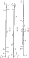
图1A是外科夹具施放器的一个示例性实施例的侧视图;Figure 1A is a side view of an exemplary embodiment of a surgical clip applier;
图1B是图1A所示外科夹具施放器的分解图;Figure 1B is an exploded view of the surgical clip applier shown in Figure 1A;
图2A是图1A所示外科夹具施放器的钳口保持器(retainer)组件的俯视图;Figure 2A is a top view of the jaw holder (retainer) assembly of the surgical clip applier shown in Figure 1A;
图2B是图2A所示钳口保持器组件的仰视图;Figure 2B is a bottom view of the jaw retainer assembly shown in Figure 2A;
图2C是图2B所示钳口保持器组件的侧视图;Figure 2C is a side view of the jaw retainer assembly shown in Figure 2B;
图2D是图2C沿线D-D剖开所示钳口保持器组件的截面图;Figure 2D is a cross-sectional view of the jaw retainer assembly shown in Figure 2C taken along line D-D;
图3A是与带有图2A-2D所示钳口保持器组件一起使用的进给发射槽(feeder shoe)的俯视图;Figure 3A is a top view of the feeder shoe used with the jaw retainer assembly shown in Figures 2A-2D;
图3B是图3A所示进给发射槽的仰视图;Fig. 3B is a bottom view of the feed launching slot shown in Fig. 3A;
图4A是构建为推进图3A和3B所示进给发射槽通过图2A-2D所示钳口保持器组件的进给杆的侧透视图;4A is a side perspective view of a feed rod configured to advance the feed launch slot shown in FIGS. 3A and 3B through the jaw retainer assembly shown in FIGS. 2A-2D;
图4B是图4A所示进给杆近端以及图2A和2B所示钳口保持器组件的侧视图,示出了在最近侧位置的进给杆;Figure 4B is a side view of the proximal end of the feed rod shown in Figure 4A and the jaw retainer assembly shown in Figures 2A and 2B, showing the feed rod in the most proximal position;
图4C是图4B所示进给杆和钳口保持器轴的侧视图,示出了在最远侧位置的进给杆;Figure 4C is a side view of the feed rod and jaw retainer shaft shown in Figure 4B, showing the feed rod in the most distal position;
图4D是所示进给杆近端与图2A和2B所示钳口保持器轴近端连接的另一个实施例的侧视图,示出在最近侧位置的进给杆;Figure 4D is a side view of another embodiment of the proximal end of the feed rod shown coupled to the proximal end of the jaw retainer shaft shown in Figures 2A and 2B, showing the feed rod in the most proximal position;
图4E是图4D所示进给杆和钳口保持器轴的侧视图,示出在最远侧位置的进给杆;Figure 4E is a side view of the feed rod and jaw retainer shaft shown in Figure 4D, showing the feed rod in the most distal position;
图4F是所示进给杆近端与图2A和2B所示钳口保持器轴近端连接的另一个实施例的侧视图,示出在最近侧位置的进给杆;Figure 4F is a side view of another embodiment of the proximal end of the feed rod shown coupled to the proximal end of the jaw retainer shaft shown in Figures 2A and 2B, showing the feed rod in the most proximal position;
图4G是图4F所示进给杆和钳口保持器轴的侧视图,示出了在中间位置的进给杆;Figure 4G is a side view of the feed rod and jaw retainer shaft shown in Figure 4F, showing the feed rod in an intermediate position;
图4H是图4F所示进给杆和钳口保持器轴的侧视图,示出了在最远侧位置的进给杆;Figure 4H is a side view of the feed rod and jaw retainer shaft shown in Figure 4F, showing the feed rod in the most distal position;
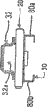
图5A是构建为与图4A所示进给杆远端连接的推进器的侧透视图;Figure 5A is a side perspective view of a pusher configured to connect to the distal end of the feed rod shown in Figure 4A;
图5B是构建为与图4A所示进给杆远端连接的推进器的另一个实施例的侧透视图;Figure 5B is a side perspective view of another embodiment of a pusher configured to connect to the distal end of the feed rod shown in Figure 4A;
图6A是夹具推进组件的截面图,其中包括图2A-2D所示钳口保持器组件、图3A和3B所示进给发射槽以及图4A所示的进给杆,示出了相对于钳口保持器组件的夹具轨道处于初始近侧位置的进给杆;6A is a cross-sectional view of the clamp advancing assembly, including the jaw retainer assembly shown in FIGS. 2A-2D , the feed launch slot shown in FIGS. 3A and 3B , and the feed rod shown in FIG. Feed rod with the clamp track of the mouth retainer assembly in the initial proximal position;
图6B是图6A所示夹具推进组件的截面图,示出向远侧方向运动的进给杆;6B is a cross-sectional view of the clip advancement assembly shown in FIG. 6A showing the feed rod moving in a distal direction;
图6C是图6B所示夹具推进组件的截面图,示出移动到进一步远端的进给杆,由此向远侧方向运动进给发射槽和布置在进给发射槽远端的夹具供应器;6C is a cross-sectional view of the clip advancement assembly shown in FIG. 6B showing the feed rod moved further distally, thereby moving the feed launch slot and the clip feeder disposed at the distal end of the feed launch slot in a distal direction ;
图6D是图6C所示夹具推进组件的截面图,示出回到图6A所示初始近侧位置的进给杆,同时进给发射槽和夹具供应器依然在图6C所示的推进位置;6D is a cross-sectional view of the clip advancement assembly shown in FIG. 6C, showing the feed rod returned to the initial proximal position shown in FIG. 6A, while the feed launch and clip feeder are still in the advanced position shown in FIG. 6C;
图6E是图6A所示推进器底透视图,其布置在图2A-2D所示钳口保持器组件的夹具轨道内,示出在最近侧位置的推进器;6E is a bottom perspective view of the pusher shown in FIG. 6A disposed within the clamp track of the jaw retainer assembly shown in FIGS. 2A-2D , showing the pusher in the most proximal position;
图6F是6E所示推进器的底透视图,示出推进器将一个夹具推进入外科夹具施放器的钳口后,在最远侧位置的推进器;6F is a bottom perspective view of the pusher shown in 6E, showing the pusher in the most distal position after it has pushed a clip into the jaws of the surgical clip applier;
图7是图1A所示外科夹具施放器的一对钳口的侧透视图;Figure 7 is a side perspective view of a pair of jaws of the surgical clip applier shown in Figure 1A;
图8是与图7所示带有钳口一起使用的凸轮的侧透视图;Figure 8 is a side perspective view of the cam for use with the jaws shown in Figure 7;
图9是推进杆适于与图8所示凸轮连接以用于相对于图7所示钳口运动凸轮的顶部透视图;Figure 9 is a top perspective view of the push rod adapted to connect with the cam shown in Figure 8 for moving the cam relative to the jaws shown in Figure 7;
图10A是图8所示凸轮连接图7所示钳口的俯视图,示出初始位置的凸轮和张开的钳口;Figure 10A is a top view of the cam shown in Figure 8 connected to the jaws shown in Figure 7, showing the cam in its initial position and the jaws opened;
图10B是图8所示凸轮连接图7所示钳口的俯视图,示出推进过钳口的凸轮和在闭合位置的钳口;Figure 10B is a top view of the cam shown in Figure 8 coupled to the jaws of Figure 7, showing the cam advanced through the jaws and the jaws in a closed position;
图11是适于与图2A-2D所示钳口保持器组件的夹具轨道远端连接的组织止挡件的顶部透视图;11 is a top perspective view of a tissue stop adapted to couple with the distal end of the clamp track of the jaw retainer assembly shown in FIGS. 2A-2D ;
图12是图1A所示外科夹具施放器远端的顶部透视图,示出图11所示的位于图7所示钳口之间的组织止挡件;12 is a top perspective view of the distal end of the surgical clip applier shown in FIG. 1A showing the tissue stop shown in FIG. 11 positioned between the jaws shown in FIG. 7;
图13是图1A所示外科夹具施放器的手柄部分的局部侧剖视图;13 is a partial side cross-sectional view of the handle portion of the surgical clip applier shown in FIG. 1A;
图14是图1A所示外科夹具施放器的触发器内部的侧透视图;14 is a side perspective view of the interior of the trigger of the surgical clip applier shown in FIG. 1A;
图15A是图1A所示外科夹具施放器的进给杆联接器一半的侧透视图;15A is a side perspective view of one half of the feed rod coupling of the surgical clip applier shown in FIG. 1A;
图15B是图15A所示的进给杆联接器另一半的侧透视图;Figure 15B is a side perspective view of the other half of the feed rod coupler shown in Figure 15A;
图16是形成部分图1A所示外科夹具施放器的夹具推进组件的柔性连杆的顶部透视图;16 is a top perspective view of the flexible linkage forming part of the clip advancing assembly of the surgical clip applier shown in FIG. 1A;
图17A是图1A所示外科夹具施放器的手柄部分的局部剖视图,示出在初始位置的夹具推进组件;17A is a partial cross-sectional view of the handle portion of the surgical clip applier shown in FIG. 1A, showing the clip advancement assembly in an initial position;
图17B是图17A所示外科夹具施放器的手柄部分的局部剖视图,示出部分致动的夹具推进组件;17B is a partial cross-sectional view of the handle portion of the surgical clip applier shown in FIG. 17A, showing a partially actuated clip advancement assembly;
图17C是图17B所示外科夹具施放器的手柄部分的局部剖视图,示出完全致动的夹具推进组件;17C is a partial cross-sectional view of the handle portion of the surgical clip applier shown in FIG. 17B, showing the fully actuated clip advancement assembly;
图17D是图17A所示外科夹具施放器的手柄部分的局部剖视图,示出已致动的夹具推进组件;17D is a partial cross-sectional view of the handle portion of the surgical clip applier shown in FIG. 17A, showing the actuated clip advancement assembly;
图18是形成部分图1A所示外科夹具施放器的夹具形成组件的闭合连杆滚柱的侧视图;18 is a side view of a close link roller forming part of the clip forming assembly of the surgical clip applier shown in FIG. 1A;
图19是与图18所示闭合连杆滚柱连接以形成图1A所示外科夹具施放器的夹具形成组件部分的闭合连杆的顶部透视图;19 is a top perspective view of the closure link connected with the closure link roller shown in FIG. 18 to form the clip forming assembly portion of the surgical clip applier shown in FIG. 1A;
图20A是与图19所示闭合连杆连接并形成部分图1A所示外科夹具施放器的夹具形成组件的闭合连杆联接器的顶部透视图;20A is a top perspective view of the closure link coupler connected with the closure link shown in FIG. 19 and forming part of the clip forming assembly of the surgical clip applier shown in FIG. 1A;
图20B是与图9所示推进杆连接的图20A所示闭合连杆的仰视图,该闭合连杆具有一偏压部件布置在其中的实施例;20B is a bottom view of the closure link shown in FIG. 20A connected to the pusher rod shown in FIG. 9, the closure link having an embodiment of a biasing member disposed therein;
图20C是与图9所示推进杆连接的图20A所示闭合连杆的仰视图,该闭合连杆具有偏压部件布置在其中的另一实施例;20C is a bottom view of the close link shown in FIG. 20A connected to the push rod shown in FIG. 9, the close link having another embodiment of a biasing member disposed therein;
图21A是图1A所示外科夹具施放器的防倒转机构的放大顶部透视图;21A is an enlarged top perspective view of the anti-backup mechanism of the surgical clip applier shown in FIG. 1A;
图21B是图21A所示防倒转机构的棘爪机构的透视图;Figure 21B is a perspective view of the pawl mechanism of the anti-backover mechanism shown in Figure 21A;
图22A是图1A所示外科夹具施放器的手柄部分的局部剖视图,示出在初始位置的防倒转机构;22A is a partial cross-sectional view of the handle portion of the surgical clip applier shown in FIG. 1A showing the anti-backup mechanism in an initial position;
图22B是图22A所示外科夹具施放器的手柄部分的局部图,示出部分致动的防倒转机构;22B is a fragmentary view of the handle portion of the surgical clip applier shown in FIG. 22A showing a partially actuated anti-backup mechanism;
图22C是图22B所示外科夹具施放器的手柄部分的局部剖视图,示出完全致动的防倒转机构;22C is a partial cross-sectional view of the handle portion of the surgical clip applier shown in FIG. 22B, showing the fully actuated anti-backup mechanism;
图22D是图22C所示外科夹具施放器的手柄部分的局部剖视图,示出防倒转机构回到初始位置;22D is a partial cross-sectional view of the handle portion of the surgical clip applier shown in FIG. 22C, showing the anti-backup mechanism returned to its original position;
图22E是图22D所示外科夹具施放器的手柄部分的局部剖视图,示出防倒转机构回到初始位置;22E is a partial cross-sectional view of the handle portion of the surgical clip applier shown in FIG. 22D, showing the anti-backup mechanism returned to the original position;
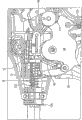
图23A是图1A所示外科夹具施放器的过载机构的分解图;23A is an exploded view of the overload mechanism of the surgical clip applier shown in FIG. 1A;
图23B是图23A所示的过载机构的局部剖视图,示出了闭合连杆滚柱第一次与翼形连杆接触;Figure 23B is a partial cross-sectional view of the overload mechanism shown in Figure 23A, showing the closing link roller first contacting the airfoil link;
图23C是图23B所示的过载机构的局部剖视图,示出了闭合连杆滚柱对翼形连杆施加力使之枢转。23C is a partial cross-sectional view of the overload mechanism shown in FIG. 23B showing the closing link rollers applying force to the wing links to pivot.
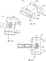
图23D是与外科夹具施放器一起使用的过载机构的另一个实施例的透视图;Figure 23D is a perspective view of another embodiment of an overload mechanism for use with a surgical clip applier;
图24A是图1A所示的外科夹具施放器的夹具量指示轮的从侧面看的透视图;24A is a perspective view from the side of the clip volume indicator wheel of the surgical clip applier shown in FIG. 1A;
图24B是图24A所示的夹具量指示轮的侧视图;Fig. 24B is a side view of the clamp amount indicating wheel shown in Fig. 24A;
图25是与图24所示的夹具量指示轮一起使用的夹具量指示器的从顶部看的透视图;Figure 25 is a perspective view from the top of a clamp volume indicator for use with the clamp volume indicator wheel shown in Figure 24;
图26A是图1A所示外科夹具施放器的手柄的一部分的侧剖视图,示出了图25的夹具量指示器和图24的夹具量指示轮的运动;26A is a side cross-sectional view of a portion of the handle of the surgical clip applier shown in FIG. 1A showing movement of the clip volume indicator of FIG. 25 and the clip volume indicator wheel of FIG. 24;
图26B是图26A所示外科夹具施放器的手柄的一部分的侧剖视图,示出了图25的夹具量指示器和图24的夹具量指示轮的进一步运动。26B is a side cross-sectional view of a portion of the handle of the surgical clip applier shown in FIG. 26A showing further movement of the clip volume indicator of FIG. 25 and the clip volume indicator wheel of FIG. 24 .
具体实施方式 Detailed ways
本发明总的提供一种外科夹具施放器以及使用外科夹具施放器在外科手术过程中对血管、导管,分流的通管等施放外科夹具的方法。如此处所述和附图所示的,示例性外科夹具施放器包括各种便于施放外科夹具的特征。然而,本领域普通技术人员应该理解,外科夹具施放器可只包括这些特征中的一些和/或可包括各种本领域已知的其它特征。在此描述的外科夹具施放器只打算表示某些示例性实施例。The present invention generally provides a surgical clip applier and a method of applying surgical clips to blood vessels, catheters, shunts, etc. during surgical procedures using the surgical clip applier. As described herein and illustrated in the accompanying drawings, the exemplary surgical clip applier includes various features that facilitate the application of surgical clips. However, those of ordinary skill in the art will appreciate that the surgical clip applier may include only some of these features and/or may include various other features known in the art. The surgical clip appliers described herein are intended to represent certain exemplary embodiments only.
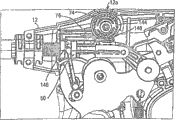
图1A示出了一个示例性外科夹具施放器10。如图所示,夹具施放器10总的包括一外壳12,该外壳具有固定手柄14和与外壳12可枢转地连接的可动手柄或触发器16。一细长轴18从外壳12伸出,且该细长轴包括一对形成在其远端的相对钳口20,用于使外科夹具弯边。细长轴18可旋转地与外壳12连接,它包括用于相对外壳12旋转轴18的旋钮22。图1B示出了图1A所示外科夹具施放器的分解图,各种组成元件将在下面更详细描述。An exemplary
图2A-12示出了外科夹具施放器10的轴18的各个组成元件的示例性实施例。总地说,参照图1B,轴18包括容纳轴组成元件的外管24,轴组成元件可包括钳口保持器组件26,它具有在其上形成有夹具轨道30和推进杆通道32的钳口保持器轴28。可使钳口20构造成与夹具轨道30的远端配合。轴组件18还可包括夹具推进组件,在一示例性实施例中该夹具推进组件可包括:进给发射槽34,其适于可滑动地布置在夹具轨道30内以推进位于其中的一连串夹具36;以及进给杆38其适合于驱动进给发射槽34通过夹具轨道30。进给杆38可包括推进器组件40,其适于与进给杆38远端配合以将最远侧的夹具推进钳口20。轴组件18还可包括夹具成形或凸轮组件,在一示例性实施例中可包括:凸轮42,其适于可滑动地与钳口20配合;以及推进杆44,其可与凸轮42联接以相对钳口20运动凸轮42。轴组件还可包括组织止挡件46,其可与夹具轨道30的远端配合,以便于相对外科手术位置定位钳口20。2A-12 illustrate exemplary embodiments of various constituent elements of the
在图2A-5中更详细地示出了一个示例性夹具推进组件的各个组成元件。首先参照图2A-2D,它们示出了钳口保持器组件26,并且它包括:细长的、基本上平的钳口保持器轴28,它具有与外管24配合的近端28a;和适于与钳口20配合的远端28b。可使用各种技术使钳口保持器轴28的近端28a与外管24配合,在所示实施例中,近端28a包括:在其相对侧形成的齿31,其适于容纳在形成在外管24内的相应的孔或开口(未示出)中;以及形成在其内的切口29,其允许近端28a的各相对侧偏转或形成一弹簧。具体地,当钳口保持器轴28插入外管24时,切口29允许钳口保持器轴28的近端28a的各相对侧彼此压缩。一旦齿31对准外管24中的相应开口,钳口保持器轴28的近端28a将返回其裙的未压缩构造,由此使齿31延伸进入相应开口,以接合外管24。在下面将对图4A进行更详细地叙述,所述装置还包括这样一个部件,以防止在装置使用期间钳口保持器轴28的近端28a的各相对侧压缩,从而防止齿31与外管24的意外脱开。The individual components of an exemplary clip advancement assembly are shown in more detail in FIGS. 2A-5 . Referring first to FIGS. 2A-2D , they illustrate the
还可以使用各种技术使钳口保持器轴28的远端28b与钳口20配合,但是,在示出的实施例中,钳口保持器轴28的远端28b包括形成于其中的数个切口或齿78,用以与形成在钳口20上的相应突起或齿94配合,这将参考图7在下面更详细地叙述。齿78使钳口20的近侧部分基本上与钳口保持器轴28共面。The
钳口保持器组件26还包括形成于其上的推进杆通道32,其用于可滑动地接收用于推进凸轮42越过钳口20的推进杆44,如下面将更详细地叙述的。可使用各种技术形成推进杆通道32,而其所具有的任何形状和尺寸依赖于推进杆44的形状和尺寸。如图2D所示,将推进杆通道32通过例如焊接固定地连接到夹持器轴28的上表面,并且该推进杆通道32具有基本上矩形形状且限定穿过其中延伸的通路32a。推进杆通道32还可沿夹持器杆28的全部或只是部分地延展。本领域普通技术人员应该理解,钳口保持器组件26无需包括为便于在外科夹具施放器10的细长轴18内的推进杆44的运动的推进杆通道32。The
如图2A-2D进一步所示,钳口保持器组件26还包括与其配合或形成在其上的夹具轨道30。所示的夹具轨道30与钳口保持器轴28的下表面配合,并且该夹具轨道向远侧延伸到钳口保持器轴28的远端28b之外,以允许夹具轨道30的远端30b与钳口20基本上对准。在使用中,将夹具轨道30构成为可在其中安置至少一个、优选为一连串夹具。因此,夹具轨道30包括相对的侧导轨80a、80b,它们适于在其中安置一个或多个夹具的相对的腿,以使夹具的腿沿轴向彼此对准。在示例性实施例中,构成的夹具轨道30可安置约二十个在生产时预先布置在夹具轨道30中的夹具。本领域普通技术人员应该理解,夹具轨道30的形状、尺寸和结构可根据夹具的形状、尺寸和结构的不同而改变,或根据其它适于被接收在其中的闭合装置(如钉合器)而改变。另外,可使用各种其它技术代替夹具轨道30来与细长轴18一起保持夹具供应。As further shown in FIGS. 2A-2D , the
夹具轨道30还包括形成于其内的数个开口30c,用于接收形成在适于布置在夹具轨道30内的进给发射槽34上的柄脚82a,如下面将更详细地叙述的。在示例性实施例中,夹具轨道30包括一定量的开口30c,这些开口至少与适于预先布置在装置10中的在使用时施放的夹具数目相应。开口30c优选地彼此是等距的,以确保每次推进该进给发射槽34时进给发射槽34上的柄脚82a与开口30c接合。虽然未示出,夹具轨道30可包括定位件而不是开口30c,或它可包括其它部件,以允许夹具轨道30与进给发射槽34接合,从而防止进给发射槽34向远侧运动而允许其向近侧运动。夹具轨道30还包括形成于其上的止挡柄脚118,如图2B所示,如下面将要更详细地描述的,可通过在进给发射槽34上形成的相应止挡柄脚有效地接合以防止进给发射槽34超出最远侧位置的运动。止挡柄脚118可具有不同结构,但在一个示例性实施例中,它是两个邻近的小凸起,它们彼此相互延伸,以包围夹具轨道的一部分,从而允许夹具通过。
在图3A和3B中更详细地显示了示例性进给发射槽34,并且它适于直接驱动夹具通过夹具轨道30。虽然进给发射槽34可有各种结构并可使用各种其它技术驱动夹具通过夹具轨道30,在示例性实施例中,进给发射槽34大致为具有近端34a和远端34b的细长形状。远端34b适于将在夹具轨道30中最近侧的夹具支住以推动该夹具通过夹具轨道30。在示出的示例性实施例中,远端34b为基本上V形形状,用于安置夹具的V形弯曲部分。远端34b还包括形成于其中的矩形槽口34c,用于允许推进器40接合最远侧夹具并将该夹具推进钳口20,如下面将要更详细地描述的。当然,远端34b可根据夹具的结构而改变,或根据与装置10一起使用的其它闭合机构而改变。An exemplary
在另一个示例性实施例中,进给发射槽34还可以包括这样一个部件,其便于进给发射槽34在夹具轨道30内向远侧运动,并基本上防止进给发射槽34在夹具轨道30内向近侧的运动。这样的结构可确保夹具在夹具轨道30内的推进和正确定位,从而允许在触发器16每次致动的情况下在钳口20之间推进最远侧的夹具,如下面将要更详细地描述的。在示出的示例性实施例中,进给发射槽34包括柄脚82a,其形成在该进给发射槽的上表面上并向近侧转角,用于接合形成在夹具轨道30内的开口30c之一。在使用时,柄脚82a的角允许进给发射槽34在夹具轨道30内向远侧滑动。每次推进进给发射槽34时,柄脚82a在夹具轨道30内从一个开口30c向远侧运动到下一个开口30c。在夹具轨道30内柄脚82a与开口30c的接合可防止进给发射槽34向近侧运动而返回到前一位置,如下面将要更详细地描述的。In another exemplary embodiment, feed
为了便于进给发射槽34在夹具轨道30内向近侧的运动,进给发射槽34包括形成在其下表面34i上的柄脚82b,如图3B所示,用于允许在进给杆38向远侧运动时由进给杆38(图4A)接合进给发射槽34。下柄脚82b与上柄脚82a在其可向近侧转角方面是类似的。在使用中,每次进给杆38向远侧运动,形成在进给杆38内的定位件84与下柄脚82b接合并在夹具轨道30内向远侧运动进给发射槽34一预定距离。接着可向近侧运动进给杆38,使其返回初始位置,下柄脚82b的角度允许柄脚82b滑动入形成在进给杆38内的下一个定位件84。如先前解释的,可不使用柄脚82a、82b和开口30c或定位件84而使用各种其它部件来控制进给发射槽34在夹具轨道30内的运动。To facilitate proximal movement of the
如先前提到的,进给发射槽34还可包括形成于其上的止挡件,当进给发射槽34在最远侧位置且在装置10中没有夹具时,该止挡件适于挡住进给发射槽34的运动。该止挡件可具有各种结构,图3A和3B示出了形成在进给发射槽34上的第三柄脚82c,该第三柄脚82c在下面方向上延伸,用于接合形成在夹具轨道30上的止挡柄脚118(图2B)。定位第三柄脚82c,以使当进给发射槽34在最远侧位置时,该柄脚接合在夹具轨道30上的止挡柄脚118,由此防止当用完供给的夹具时进给发射槽34和进给杆38的运动。As previously mentioned, the
图4A示出一示例性进给杆38,其用于驱动进给发射槽34通过钳口保持器组件26的夹具轨道30。如所示,进给杆38具有大致为带有近端38b和远端38a的细长形状。进给杆38的近端38a适于与进给杆联接器50配合(图1B),这将在下面更详细地描述。进给杆联接器50与进给连杆52配合,当触发器16致动时,该进给连杆52可有效地在细长轴18中沿远侧方向可滑动地运动进给杆38。进给杆38的近端38b适于与推进器40、40’配合,其示例性实施例如图5A和5B所示,该推进器可有效地将布置在夹具轨道30内的最远侧夹具驱动进入钳口20,这将在下面更详细地描述。FIG. 4A shows an
如先前提到的,进给杆38的近端38a可包括这样一个元件,其可在该装置使用过程中防止钳口保持器轴28的近端28a的各相对侧的压缩(图2A和2B)从而防止齿31与外管24意外脱开。在一个示例性实施例中,图4A-4C所示,进给杆38的近端38a可包括形成于其上的突起39,其适于延伸入形成在钳口保持器轴28的近端28a内的开口29。当进给杆38在最近侧位置(即,当触发器16在张开位置)时,将突起39定位在开口29的近端,如图4B所示,从而允许钳口保持器轴28的近端28a压缩以允许轴28滑入外管24。当进给杆38在最远侧位置(即,当触发器16在至少部分闭合的位置)时,将突起39定位在邻近齿31的中间位置,如图4C所示,以防止钳口保持器轴28的近端28a压缩。这在该装置使用过程中特别有利,因为突起39在该装置使用期间将防止钳口保持器轴28与外管24的意外脱开。尽管在图4A-4C中示出了具有带有圆边的矩形截面形状的突起39,突起39可具有各种其它形状和尺寸。例如,如图4D和4E所示的,突起39’具有带有锥形端的类似三角形的截面形状,其适于延伸到齿31之间以进一步确保在装置使用过程中钳口保持器轴28的近端28a不被压缩。可使用多于一个的突起。例如,图4F-4H示出了另一个实施例,其中进给杆38的近端38a’可包括形成于其上并彼此相隔的两个突起39a,39b。两个突起39a、39b可以如图4F所示当进给杆38在最近端位置时,以及如图4H所示当进给杆38在最远侧位置时防止钳口保持器轴28的近端28a压缩。钳口保持器轴28的近端28a的压缩只发生在当进给杆38在中间位置、齿31定位在突起39a、39b之间(如图4G所示)的情况时。As previously mentioned, the
还如先前提到的,进给杆38可包括形成在其中的定位件84,用于与形成在进给发射槽34处的下柄脚82b接合。定位件84的数量可不同,但在示例性实施例中,进给杆38具有的定位件84的数量对应于或大于适于由装置10施放的夹具的数量,而更优选的是,它具有比适于由装置10施放的夹具的数量多一个的定位件84。作为非限制性的例子,进给杆38可包括形成在其内的十八个定位件84,用于施放预先布置在夹具轨道30内的十七个夹具。这样的结构允许进给杆38推进进给发射槽34十七次,由此推进十七个夹具进入钳口20以进行施放用于使用。定位件84还优选地彼此等距,以确保每次推进进给杆38时都可由进给杆38接合并推进进给发射槽34。Also as previously mentioned, the
进给杆38还可包括这样一个元件,其可以控制进给杆38相对夹具轨道30的运动量。这样的结构可确保触发器16每次致动时将进给发射槽34推进一预定距离,由此只将单个夹具推进钳口20。尽管可使用各种技术控制进给杆38向远侧运动,在示例性实施例中,进给杆38可包括形成于其上的突起86,其适于被可滑动地接收在形成于钳口保持器轴28内的相应的狭槽88(图2B)内。狭槽88的长度可有效地限制其中的突起86的运动,这样就限制了进给杆38的运动。据此,在使用中,进给杆38可在固定的近侧位置和固定的远侧位置之间相对夹具轨道30滑动,由此随着进给杆38的每次推进,允许进给杆38将进给发射槽34推进一预定距离。The
图5A示出了适于与进给杆38的远端38b配合的推进器40的一个示例性实施例,它可有效地将最远侧的夹具从夹具轨道30驱动进入钳口20。可使用各种技术使推进器40与进给杆38配合,但在示出的实施例中,推进器40的近端40a为内连接器的形式,该内连接器适于接收形成在进给杆38的远端38b的外连接器。推进器40优选地与进给杆38固定地配合,然而它可任选的与进给杆38一体形成。进给杆38的远端40b优选地适于将夹具推进钳口20,并且推进器40的远端40b可包括例如形成在其上的夹具推进构件90。该夹具推进构件90可具有各种形状和尺寸,但在示出的实施例中,它具有细长的形状,并且在其远端形成有凹槽92,用于安置夹具的弯曲部分。凹槽92的形状可根据夹具的具体结构而不同。夹具推进构件90还可以相对推进器40的纵向轴线A向上方向伸出一角度。这种结构允许夹具推进构件90延伸入夹具轨道30以接合夹具,同时推进器40的其余部分基本上与夹具轨道30平行地延伸。图5B示出了推进器40’的夹具推进构件90’的另一个示例性实施例。在此实施例中,夹具推进构件90’稍微更窄点,并且它具有形成在其最远端的小凹槽92’。在使用中,推进器40只将布置在夹具轨道30内最远侧的夹具接合和推进钳口20。这是由于进给杆38的定位,如先前描述的,它可滑动地在固定的近侧和远侧位置之间运动。FIG. 5A illustrates an exemplary embodiment of a
图6A-6G示出了在使用中的夹具推进组件,具体的,图6A-6D示出为推进进给发射槽34和夹具供给器36在夹具轨道30内进给杆38的运动,而图6E-6F示出推进器40的将最远侧的夹具推进钳口20的运动。在外壳12内的用于致动夹具推进组件的组成元件将在下面更详细地描述。Figures 6A-6G illustrate the clamp advancing assembly in use, specifically, Figures 6A-6D illustrate the movement of the
如图6A所示,在不工作位置时,进给杆38处于最近侧位置,以使突起86在钳口保持器轴28内的细长狭槽88中近侧定位。进给发射槽34布置在夹具轨道30内,假设还没有使用装置10,进给发射槽34处于最近侧位置,以使在进给发射槽34上的上柄脚82a与在夹具轨道30内形成的最近侧或第一开口30c1接合,以防止进给发射槽34向近侧运动,而定位进给发射槽34上的下柄脚82b定位在进给杆38中的第一定位件841和第二定位件842之间,以由进给杆38沿上面方向偏压下柄脚82b。进给杆中的定位件84顺序地标记为841、842等,在夹具轨道30内的开口30c顺序标记为30c1、30c2等。如图6A进一步所示,一连串夹具36(顺序标记为361、361、...36x,并且36x为最远侧的夹具)进给发射槽34远侧定位在夹具轨道30内。As shown in FIG. 6A , in the rest position, feed
在触发器16致动时,向远侧推进进给杆38,从而导致突起86在狭槽88中向远侧滑动。随着进给杆38向远侧运动,进给发射槽34上的下柄脚82b将滑入在进给杆38中的第一定位件841。进给杆38的进一步向远侧运动将造成第一定位件841与下柄脚82b接合(如图6B所示),并沿远侧方向运动进给发射槽34和夹具供给器361、362等。如图6C所示,当突起86抵接在钳口保持器轴28内的细长狭槽88的远端时,可防止进给杆38向更远侧的运动。在该位置,进给发射槽34已被推进到一预定距离,以在夹具轨道30内,将夹具供给器361、362、...36x推进预定距离。进给发射槽34的上柄脚82a已经被推入在夹具轨道30内的第二开口30c2中,以防止进给发射槽34向近侧运动,而进给发射槽34上的下柄脚82b仍将由进给杆38内的第一定位件841接合。Upon actuation of
进给杆38从在图6A中所示的初始的最近侧位置运动到在图6C中所示的最终的最远侧位置将把最远侧的夹具36x推进钳口20。具体的,如图6E所示,进给杆38向远侧的运动将造成连接到进给杆38远端的推进器40的夹具推进构件90与布置在夹具轨道30内的最远侧的夹具36x接合并将该夹具36x推进钳口20,如图6F所示。在示例性实施例中,推进器40将在接合并开始进给发射槽34的推进之前接合并开始最远侧夹具36x的推进。结果是最远侧的夹具36x将推进一比进给发射槽34行进的距离更大的距离。这种结构只允许最远侧的夹具36x推进钳口20中,而不会将另外的夹具意外地推进钳口20中。Movement of the
一旦夹具36x部分或完全形成,就松开触发器16以释放已形成的夹具36x。触发器16的释放将沿近侧方向拉回进给杆38,直到突起86回到在细长狭槽88中的初始最近侧位置,如图6D所示。在向近侧拉回进给杆38时,进给发射槽34将不会向近侧运动,因为上柄脚82a将与在夹具轨道30内的第二开口30c2接合。下柄脚82b不干涉进给杆38向近侧的运动,而一旦如所示地进给杆38在初始最近侧位置处,下柄脚82b将被定位在进给杆38内的第二定位件842和第三定位件843之间。Once the clamp 36x is partially or fully formed, the
可以重复该处理以将另一个夹具推进钳口20。随着触发器16的每一次致动,由下一个定位件,即,形成在进给杆38中的定位件842接合下柄脚82b,进给发射槽34的上柄脚82a向远侧运动进入下一个开口,即,在夹具轨道30上的开口30c3,最远侧的夹具将被推进钳口20并释放。当装置10包括预定量的夹具,例如十七个夹具时,触发器16可致动十七次。一旦已经施放完最后的夹具,进给发射槽34上的止挡件(例如第三柄脚82c)可与夹具轨道30上的止挡柄脚118接合,以防止进给发射槽34进一步向远侧运动。This process can be repeated to advance another clamp into
图7-9示出了夹具形成组件的各种示例性组成元件。首先参照图7,其示出了钳口20的示例性实施例。如前面提到的,钳口20可包括近侧部分20a,其具有与形成在钳口保持器轴28上的相应齿78配合的齿94。然而,可以使用其它技术使钳口20与钳口保持器轴28配合。例如可使用鸠尾连接、外-内连接等。或者,钳口20可与夹持器杆28一体形成。钳口20的远侧部分20b适于接收其之间的夹具,远侧部分20b可包括相对的第一和第二钳口构件96a、96b,它们可相对彼此运动。在示例性实施例中,钳口构件96a、96b被偏压成一张开位置,需要作用力使钳口构件96a、96b向彼此运动。钳口构件96a、96b每一个可包括形成于其相对内表面中的沟槽(只显示了一个沟槽97),用于接收与钳口构件96a、96b对准的夹具的腿。钳口构件96a、96b每一个还可包括形成于其内的凸轮轨道98a、98b,用于允许凸轮42与钳口构件96a、96b接合,并使钳口构件96a、96b向彼此运动。在示例性实施例中,凸轮轨道98a、98b形成在钳口构件96a、96b的上表面上。7-9 illustrate various exemplary constituent elements of a clip forming assembly. Referring first to FIG. 7 , an exemplary embodiment of
图8示出了示例性凸轮42,用于与钳口构件96a、96b滑动配合并接合。凸轮42可具有各种结构,但在示出的实施例中,它包括适于与推进杆44配合的近端42a(在下面更详细地描述),它还包括适于与钳口构件96a、96b接合的远端42b。可使用各种技术使凸轮42与推进杆44配合,但在示出的实施例中,凸轮42包括形成在其中的内或键形切口100,该切口100适于接收形成在推进杆44的远端44b上的外或键构件102。阳的构件102在图9中更详细的显示出外构件102,其中示出了推进杆44。如图所示,外构件102具有与切口100的形状相对应的形状,以允许两个构件42、44进行配合。本领域普通技术人员应该理解,凸轮42和推进杆44可选地彼此一体形成。推进杆44的近端44a可适于与闭合连轴组件配合(在下面更详细地描述)用于相对钳口20运动推进杆44和凸轮42。FIG. 8 illustrates
如图8进一步所示,凸轮42还可包括形成于其上的突起42c,其适于被形成在钳口20内的细长狭槽20c接收。在使用中,突起42c和狭槽20c可用来形成用于夹具形成组件的近侧止挡件。As further shown in FIG. 8 , the
再参照图8,凸轮42的远端42b适于与钳口构件96a、96b接合。虽然可使用各种技术,在示出的示例性实施例中,远端42b包括形成在其中的凸轮形槽或锥形凹槽104,用于可滑动地接收在钳口构件96a、96b上的凸轮轨道98a、98b。在使用中,如图10A和10B所示,可将凸轮42从其中钳口构件96a、96b彼此间隔一段距离的近侧位置推进到其中定位钳口构件96a、96b彼此邻近并处于闭合位置的远侧位置。随着凸轮42被推进越过钳口构件96a、96b,锥形凹槽104将向彼此推动钳口构件96a、96b,由此使布置在其中的夹具弯边。Referring again to FIG. 8, the
如上面提到的,外科夹具施放器10还可包括组织止挡件46,它可用于便于在手术部位的组织在钳口20内的定位。图11示出了具有近端和远端46a、46b的组织止挡件46的示例性实施例。近端46a可适于与夹具轨道30的远端配合,以用于邻近钳口20定位组织止挡件46。但是,组织止挡件46可与夹具轨道30一体地形成,或它适于与轴18的各种其它组成元件配合或一体地形成。组织止挡件46的远端46b可具有这样的形状,其适于在其之间安置脉搏管、导管、分流的通管等以进行定位并使钳口20相对目标位置对准。如图11所示,组织止挡件46的远端46b基本上为V形。远端46b还具有弯曲结构,以易于通过套管针或其它通道管放置装置。组织止挡件46的远端46b还可选地包括其它部件,以用于夹具的运动。例如,如图11所示,组织止挡件46包括形成在远端46b的中间部分的斜面47,用于保持使夹具与推进器组件40的末端对准。具体的,斜面47可允许夹具的顶点沿其安放,以防止夹具相对推进器组件40变为不对准,该推进器组件40沿远侧方向推动夹具。本领域普通技术人员应该理解,组织止挡件46可有各种其它结构,并且可包括各种其它部件以易于夹具沿其推进。As mentioned above, the
图12示出了使用中的组织止挡件46。如图所示,将组织止挡件46刚好定位在钳口20下面,且所在的位置允许脉管、导管、分流的通管等在钳口20之间被接收。如进一步所示出的,在钳口20之间定位外科夹具36,以使夹具36的弯曲部分36a与组织止挡件46对准。这将允许夹具36的腿36b环绕脉管、导管、分流的通管或其它目标位置完全定位。Figure 12 shows the
图13-26B示出了用于控制夹具的推进和形成的外壳12的各种示例性内部组成元件。如上面描述的,外科夹具施放器10可包括这里公开的某些或全部,并且它可包括本领域已知的各种其它部件。在某些示例性实施例中,夹具施放器10的内部组成元件包括:夹具推进组件,其与轴18的夹具推进组件联接,用于推进至少一个夹具通过细长轴18而在钳口20之间定位夹具;以及夹具形成组件,它可与轴18的夹具形成组件连接,用于闭合钳口20以形成部分或全部闭合的夹具。其它示例性部件包括:用于控制触发器16运动的防倒转机构,用于防止由夹具形成组件施加到钳口20的力过载的过载机构,以及用于指示留在装置10中的夹具数量的夹具数量指示器。13-26B illustrate various exemplary internal components of
图13-16D示出了用于实施在轴18中进给杆38的运动的外壳12的夹具推进组件的示例性实施例。通常,夹具推进组件包括:与触发器16连接的触发器插入件(insert)48,与进给杆38的近端38a配合的进给杆联接器50,以及在触发器插入件48和进给杆联接器50之间延伸的进给连杆52,该连杆用于将运动从触发器插入件48传递到进给杆联接器50。13-16D illustrate an exemplary embodiment of a clamp advancing assembly of
图14更详细地示出了触发器插入件48。触发器插入件48的形状可根据外壳12的其它组成元件而改变,但在示出的实施例中,触发器插入件48包括适于与外壳12以可枢转的方式配合的中央部分48a,以及适于伸入触发器16并与触发器16配合的细长部分48b。中央部分48a可包括从中延伸的穿孔106,其用于接收用于以可枢转的方式使触发器插入件48与外壳12配合的轴。中央部分48a还可包括形成于上侧边缘的用于接收进给连杆52的一部分的第一凹槽108。第一凹槽108优选地具有允许进给连杆52的一部分在其中延伸的尺寸和形状,以便当触发器插入件48由于触发器16的运动枢转时,迫使进给连杆52枢转。如图14所示,第一凹槽108基本上是细长的并包括形成在其中的基本上为圆形的部分,该部分用于安置形成在进给连杆52近端上的轴,如参照图16更详细描述的。触发器插入件48还包括:第二凹槽110,其形成于后侧边缘上,用于接收与用于运动凸轮42以闭合钳口20的推进杆44联接的闭合连杆滚柱54;形成于其底侧边缘的棘齿112,其用于与控制触发器16的运动的棘爪60配合,如下面将更详细描述的。Figure 14 shows the
图15A和15B更详细地示出了示例性的进给杆联接器50,它适于将进给杆38的近端连接到进给连杆52的远端。虽然可使用各种技术使进给杆联接器50与进给杆38的近端38a配合,在示出的示例性实施例中,由两个单独的半个50a、50b形成进给杆联接器50,它们一起配合以保持在其之间的进给杆38的近端38a。当配合时,两个半个50a、50b一起限定中央轴50c,其具有形成在其相对端上的基本上圆形的凸缘50d、50e的,并限定其之间的用于安置进给连杆52的远侧部分的凹槽50f。中央杆50c限定一贯穿其中的腔50g,其用于接收进给杆38的近端38a和用于将进给杆38相对进给杆联接器50锁定在基本上固定的位置处。然而,进给杆联接器50可与进给杆38一体地形成,而它可具有易于与进给连杆52配合的各种其它形状和尺寸。15A and 15B illustrate an exemplary
图16示出了示例性进给连杆52,其可在触发器插入件48和进给杆联接器50之间延伸。通常,进给连杆52为带有近端和远端52a、52b大致平的细长的形状。近端52a适于可旋转地位于触发器插入件48的第一凹槽108内,并且如前所述,它可包括贯穿其中的轴53(图1B)。轴53可适于在触发器插入件48的第一凹槽108内枢转,由此允许触发器插入件48枢转进给连杆52。进给连杆52的远端52b可适于连接到进给杆联接器50,在示例性实施例中,它包括相对的臂114a、114b,它们形成于该远端52b上并限定在其之间的用于安置进给杆联接器50的中央轴50a的开口116。当进给连杆52绕枢轴X枢转时,臂114a、114b有效地与联接器50接合并移动它。由进给连杆52与外壳12连接的位置限定枢轴X,并且它可被定位在进给连杆52上的任何位置,但在示出的实施例中,它被定位在邻近进给连杆52的近端52a处。FIG. 16 illustrates an
在示例性实施例中,进给连杆52可以是柔性的,以消除对夹具推进组件和夹具形成组件校准的需要。具体的,进给连杆52甚至在进给杆38和进给杆联接器50在最远侧位置后允许触发器16继续运动到闭合位置,并且它为夹具形成和推进组件提供一些自由度。换句话说,在触发器闭合期间,触发器16相对进给杆38是适应性的。In an exemplary embodiment, feed
进给连杆52的具体刚度和强度可根据夹具推进组件和夹具形成组件的结构而改变,但在一个示例性实施例中,进给连杆52的刚度在每英寸75到110lbs的范围内,而更优选的是约每英寸93lbs(在连杆52和进给杆联接器50之间的界面处测量),它的强度在20lbs到50lbs的范围内,而更优选的是约35lbs。进给连杆52还可以由各种材料制成,包括各种聚合物、金属等。一示例性的材料是强化玻璃聚醚酰亚胺,但可使用一定数量的强化热塑性塑料,包括强化玻璃液晶聚合体、强化玻璃尼龙、以及这些和类似的热塑性塑料的强化碳纤维变体。还可使用强化纤维热固性聚合物,例如热固性聚酯。进给连杆52还可以由金属制成(例如弹簧钢),以实现限定的弹性和可控制的强度的所需结合。The specific stiffness and strength of the
图17A和17B示出了使用中的示例性夹具推进组件。图17A示出了初始位置,其中触发器16停驻在张开位置,进给杆联接器50和进给杆38在最近侧位置,进给连杆52在触发器插入件48和进给杆联接器50之间延伸。如前所述,在初始张开位置中,在进给杆38上的突起86在钳口保持器轴28内的细长狭槽88的近端定位。第一偏压构件(例如弹簧120)与触发器插入件48和外壳12连接,以使触发器插入件48和触发器16保持在张开位置,而第二偏压构件(例如弹簧122)在使轴18可旋转地与外壳12配合的轴联接器124和进给杆连接器50之间延伸,以将进给杆联接器50和进给杆38保持在最近侧位置。17A and 17B illustrate an exemplary clip advancing assembly in use. Figure 17A shows the initial position with the
当触发器16被致动并向闭合位置(即,向固定手柄14)运动以克服由弹簧120、122施加偏压力时,触发器插入件48开始沿逆时针方向枢转,如图17B所示。结果,迫使进给连杆52沿逆时针方向枢转,由此向远侧运动进给杆联接器50和进给杆38。在进给杆38上的突起86在钳口保持器轴28中的细长狭槽88内向远侧运动,由此推进进给发射槽34和布置在夹具轨道内的夹具36。弹簧120在外壳与触发器插入件48之间延伸,且弹簧122在进给杆联接器50和轴联接器124之间受到压缩。When the
随着触发器16被进一步致动且触发器插入件48继续枢转,进给杆联接器50和进给杆38将最终达到最远侧位置。在该位置处,进给杆38上的突起86被定位在钳口保持器轴28中的狭槽88的远端处,并且夹具被定位在钳口20之间,如前所述。弹簧122在轴联接器124和进给杆联接器50之间被完全压缩,进给连杆52将弯曲,如图17C和17D所示。当进给连杆52弯曲时,更优选的是一旦进给连杆52完全弯曲时,就致动夹具形成组件以闭合钳口20。在致动夹具形成组件期间(例如致动的第二阶段),进给连杆52将保持弯曲,以使触发器插入件48相对于夹具推进组件、特别是进给杆38是适应性的。As
图18-20更详细示出了外壳12的示例性夹具形成组件。通常,夹具形成组件布置在外壳12内并可有效地相对钳口20运动推进杆44和凸轮42,以将钳口20运动到闭合位置,并由此使在其之间定位的夹具弯边。虽然夹具形成组件可有各种结构,在示出的示例性实施例中,夹具形成组件包括:闭合连杆滚柱54,其可滑动地连接到触发器插入件48;闭合连杆56,春连接到闭合连杆滚柱54;以及闭合联接器58,其连接到闭合连杆56和推进杆44。18-20 illustrate exemplary clip-forming components of
图18更详细地示出了闭合连杆滚柱54,如所示,闭合连杆滚柱54包括中央轴54a,其具有在邻近其相对终端处形成的基本上圆形的凸缘54b、54c。中央轴54a可适于位于触发器插入件48内的第二凹槽110中,以使凸缘54b、54c接收于触发器插入件48的各相对侧上。中央轴54a还适于与闭合连杆56的相对的臂126a、126b配合,以将该臂定位在触发器插入件48的各相对侧上。Figure 18 shows the
图19更详细示出了闭合连杆56的一个示例性实施例,如图所示,它具有相对的臂126a、126b,它们彼此相隔一定距离。每个臂126a、126b包括:近端128a、128b,它们适于与闭合连杆滚柱54的中央轴54a接合;以及远端130a、130b,它们适于与闭合联接器58配合,以用于将闭合连杆滚柱54和闭合连杆56连接到推进杆44。在示例性实施例中,每个臂126a、126b的近端128a、128b适于与闭合连杆滚柱54可枢转地配合,臂126a、126b可包括例如形成于其上的钩状件132a、132b,用于与中央轴54a接合。钩状件132a、132b沿相对方向延伸,以易于在闭合连杆56和闭合连杆滚柱54之间接合。臂126a、126b的远端130a、130b彼此配合,且它们可包括延伸贯通的腔134,以用于接收使闭合连杆56与闭合联接器58枢转地配合的轴。本领域普通技术人员应该理解,可使用其它各种技术使闭合连杆56与闭合连杆滚柱54和闭合联接器58配合。Figure 19 shows an exemplary embodiment of the
图20A更详细示出了示例性闭合联接器58,如图所示,它包括近侧部分58a,它具有两个臂136a、136b,该臂带有延伸贯通的腔138a、138b,所述腔138a、138b可的并适应性地与闭合连杆56的腔134对准,以用于接收杆而使两组成元件配合。闭合联接器58还包括远端部分58b,其适于与推进杆44的近端44a配合(图9)。在示例性实施例中,闭合联接器58包括切口59(图20B和20C),该切口形成于其中并具有适于安置推进杆44的近端44a的形状。闭合联接器58的远侧部分58b可形成为当触发器16在张开位置时接收进给杆联接器50的一部分。本领域普通技术人员应该理解,可使用各种其它配合技术使闭合联接器58与推进杆44配合,且闭合联接器58和推进杆44可选地彼此一体地形成。FIG. 20A shows an
在图20B和20C示出的另一个示例性实施例中,可将偏压构件布置在切口59中,以向远侧偏压推进杆44。这种结构可防止夹具从钳口处意外释放,特别是在闭合的早期阶段,如果使用者在触发器16上放松。具体的,虽然下面将要更详细地描述的防倒转机构可适于防止触发器16张开,直到触发器16到达预定位置,防倒转机构允许触发器16的一些轻微运动。这样,在使用者在触发器16上放松并将触发器16轻微张开的事件发生时,偏压构件将向远侧偏压推进杆44,以此使推进杆44基本上保持固定位置。虽然可使用各种偏压构件,在图20B示出的实施例中,偏压构件是悬壁梁61,其定位在推进杆44的近端44a和凹槽59的后壁之间,以向远侧偏压推进杆44。悬壁梁61可由形状记忆材料(例如镍钛诺)构成,当对其施加指向近侧的力时允许梁61弯曲或变平直。悬壁梁61可由其它各种材料构成,例如弹簧钢或强化聚合物,并可使用多根梁。图20C示出为盘簧或其它类型的弹簧63形式的偏压构件的另一个实施例。如图所示,弹簧63布置在推进杆44的近端44a和凹槽59的后壁之间,以向远侧偏压推进杆44。当对其施加指向近侧的力时,弹簧63被压缩。本领域普通技术人员应该理解,可使用各种其它偏压构件,包括弹性体压缩构件。In another exemplary embodiment, shown in FIGS. 20B and 20C , a biasing member may be disposed in the
返回参照图17A-17D,在使用中,当触发器16从张开位置开始向闭合位置运动时,闭合连杆滚柱54将在触发器插入件48中的凹槽110中滚动。一旦进给杆38和进给杆联接器50处于最远侧位置,如图17C所示,触发器16的进一步致动将导致触发器插入件48内的凹槽110与闭合连杆滚柱54接合,从而迫使其与触发器插入件48一起枢转,如图17D所示。结果,闭合联接器58将向远侧运动,由此导致推进杆44向远侧运动。当推进杆44向远侧推进时,推进凸轮42越过钳口20,以闭合钳口20并使在其间定位的夹具弯边。触发器16可选地部分闭合以只部分闭合钳口20并使接在其间定位的夹具部分弯边。下面将要更详细地描述用于易于可选择地使其间定位的夹具完全和部分闭合的示例性技术。一旦施放了夹具,可松开触发器16,以此允许弹簧120将触发器插入件48拉回到其初始位置,并允许弹簧122迫使进给杆联接器50和进给杆38回到近侧位置。当触发器插入件48返回到其初始位置时,闭合连杆滚柱54同样返回到其初始位置,以此将闭合连杆56、闭合联接器58和推进杆44向近侧拉。Referring back to FIGS. 17A-17D , in use, the
外科夹具施放器10还可包括各种其它部件以便于装置10的使用。在一示例性实施例中,外科夹具施放器10包括用于控制触发器16运动的防倒转机构。具体的,防倒转机构可防止在部分闭合冲程期间触发器16的张开。然而,一旦触发器达到预定位置(在该点已在钳口之间定位的夹具可部分地弯边),防倒转机构可释放触发器,从而允许触发器张开并释放夹具,或闭合以使夹具完全弯边,如使用者所希望的。
图21A和21B示出了棘轮形式的防倒转机构的一个示例性实施例。如图所示,棘轮包括形成于触发器插入件48上的一组齿112,和适于可旋转地布置在外壳12内且邻近触发器插入件48定位的棘爪60,使触发器16的闭合和触发器插入件48的枢轴运动导致棘爪60与齿112接合。将齿112构成为防止棘爪60的旋转,直到棘爪60达到预定位置,在该位置点棘爪60可自由旋转,由此允许触发器16张开或闭合。预定位置优选地对应于钳口20部分闭合的位置。在一示例性实施例中,如图所示,齿112包括具有防止棘爪60相对其旋转的尺寸的第一组齿112a(例如十个齿),当棘爪60与齿112的第一组齿112a接合时可防止触发器16张开。齿112还包括最后的或终端齿,称为托科(tock)齿112b,当棘爪60与托科齿112b接合时,它具有允许棘爪60相对其旋转的尺寸。特别的,托科齿112b优选地具有基本上大于第一组齿112a尺寸的尺寸,以使在第一组齿112a和托科齿112b之间形成相对大的槽口140。槽口140具有允许棘爪60在其中枢转的尺寸,这样允许棘爪60选择性地移出托科齿112b或返回到第一组齿112a。本领域普通技术人员应该理解,托科齿112b可与第一组齿112a具有相同尺寸或较小尺寸,同时还提供形成在其之间的槽口140以允许棘爪60在其中枢转。Figures 21A and 21B illustrate an exemplary embodiment of an anti-backup mechanism in the form of a ratchet. As shown, the ratchet includes a set of
图22A-22D示出了使用中的棘轮机构。如图22A所示,当开始向闭合位置移动触发器16时,棘爪60与第一组齿112a接合,由此防止触发器16张开。触发器16的进一步致动将造成棘爪60推进通过第一组齿112a直到棘爪60到达邻近托科齿112b的槽口140。一旦棘爪60到达托科齿112b(在该点由于凸轮42部分地向远侧运动越过钳口20,钳口20部分闭合),棘爪60可自由旋转,由此如使用者所希望地允许触发器16张开或闭合。图22C示出了触发器16处于完全闭合位置,而图22D和22E示出触发器16回到张开位置。Figures 22A-22D illustrate the ratchet mechanism in use. As shown in FIG. 22A, when the
棘轮机构还可以构造成能发出听得见的声音,以指示钳口20的位置。例如,当棘爪60与第一组齿112a接合时发出第一种声音,而当棘爪60与托科齿112b接合时发出第二种不同的声音,例如,高声。结果,当触发器16达到棘爪60与达托科齿112b接合的预定位置时,声音指示使用者钳口20处于部分闭合位置。使用者可松开触发器16以释放部分闭合的夹具,或他们可完全闭合触发器16,以完全闭合夹具。The ratchet mechanism can also be configured to emit an audible sound to indicate the position of the
在另一个示例性实施例中,外科夹具施放器10包括过载机构,其适用于防止由触发器16施加到钳口20上的力的过载。典型地,在外科夹具施加期间,需要一定的力闭合钳口20并围绕在其间定位的组织使夹具弯边。由于形成过程的进行和至少部分地闭合夹具,继续闭合环绕夹具的钳口20所需的力明显上升。据此,在示例性实施例中,过载机构具有与闭合钳口20所需的力相关联的阻力。换句话说,过载机构的阻力可随着闭合钳口20所需的力的升高而升高。然而,该阻力优选地稍微大于闭合钳口20所需的力,以防止过载机构的意外致动。结果,如果当触发器16开始致动时防止钳口20闭合,所需克服过载机构的阻力的力相对较低。当钳口20张开或只部分打开时这对更易变形的钳口20特别有利。过载机构在夹具成形早期更容易致动以防止钳口的变形。相反,当钳口20基本上闭合时,阻力相对较高以在将很大的施加到钳口20时只致动过载机构。In another exemplary embodiment,
图23A示出了过载机构62的一个示例性实施例,示出了其分解图。通常,过载机构包括由两个半个64a、64b形成的过载外壳64,并包括翼形连杆66(profile link)、肘节连杆68(toggle link)、枢转连杆(pivot link)70偏压组件72。偏压组件72包括弹簧柱150,其与外壳连接并包括用于接收柱塞154的延伸贯通的穿孔。弹簧152围绕弹簧柱150设置,柱塞154延伸通过弹簧柱150并包括形成于其上的头部154a,该头部适于抵接弹簧152。枢转连杆70为大致L形并可由延伸贯通的枢轴销156连接到外壳64。枢转连杆70的近端70a可与柱塞154的头部154a接触,而枢转连杆70的远端70b可由枢轴销156可枢转地连接到肘节连杆68。肘节连杆68又连接到翼形连杆66,该翼形连杆66可滑动地并枢转地定位于外壳64内并邻近形成在外壳内的开口64d。外壳64内的翼形连杆66的枢转运动可通过例如枢轴销158来实现,该枢轴销延伸贯通翼形连杆66并布置在形成于外壳64的每一半个64a、64b内的第一狭槽160a内(只示出了一个狭槽);内翼形连杆66在外壳64的可滑动运动可通过例如形成在翼形连杆66上的相对突起168a、168b实现,该突起被形成于外壳64的每一半个64a、64b内的第二狭槽160b(只示出了一个狭槽)所接收。Figure 23A illustrates an exemplary embodiment of the
在使用中,翼形连杆66适于接收来自夹具形成组件的力并用偏压组件72的阻力反抗该力。具体地,过载机构62使用弹簧152与肘节连杆68和枢转连杆70一起从绕枢轴销158旋转或相对外壳64滑动来偏压翼形连杆66。关于旋转方面,由压缩弹簧152作用的力传递通过肘节连杆68和枢转连杆70传递,以便抵抗外壳64将旋转力矩施加到翼形连杆66。这样该组件使翼形连杆66阻止相对外壳64的旋转。如果由从闭合连杆滚柱54向翼形连杆66的径向载荷产生的力矩超过枢转连杆70和肘节连杆68的力矩,翼形连杆66开始旋转,使肘节连杆68弯曲(buckling)并造成枢转连杆70进一步压缩弹簧152。关于滑动方面,枢转连杆70、肘节连杆68和翼形连杆66对准,以使滑动力(滑动的阻力)是弯曲肘节连杆68和枢转连杆70所需的力。如果从闭合连杆滚柱54向翼形连杆66的径向载荷超过连杆机构的弯曲力,随着翼形连杆66向近侧滑动,枢转连杆70进一步压缩弹簧152。In use, the
这在图23B-23C中更详细地显示出,如所示的,在外壳64中的开口64d允许夹具形成组件的闭合连杆滚柱54靠着翼形连杆66滚动。结果,当致动触发器16并使其向闭合位置运动时,闭合连杆滚柱54和翼形连杆66施加作用力。但是,过载弹簧152的阻力将使翼形连杆66保持在基本上固定的位置,除非由闭合连杆滚柱54施加的力增加为大于阻力(例如,阈值力)的力。这可由例如定位在钳口20之间的外部物质造成,或当钳口20在其之间带有夹具和脉管、导管、分流的通管等的情况下完全闭合时造成的。当钳口20不能进一步闭合时,由触发器16的闭合运动施加到闭合连杆滚柱54的力被传递到翼形连杆66,该翼形连杆66其将在外壳64内枢转和滑动,由此造成枢转连杆70枢转,这迫使柱塞154压缩过载弹簧152。This is shown in more detail in FIGS. 23B-23C , where an
如前所提到的,致动过载机构所需的力与闭合钳口20所需的力有关,其随着使触发器16运动到闭合位置而增加。这可由翼形连杆66的结构来实现。具体的,当闭合连杆滚柱54首先与翼形连杆66接触并处于在较低的位置时,翼形连杆66可在外壳64内枢转,如图23B所示。随着闭合连杆滚柱54沿翼形连杆66向上运动,因为翼形连杆66必须在外壳64内滑动,所以克服过载机构的阻力所需的力增加,如图23C所示。枢转翼形连杆66所需的力小于使翼形连杆66滑动所需的力。因此,如果当触发器16开始致动时,例如由于外部物质使钳口20不能闭合,只需较小的力就可使成闭合连杆滚柱54将力传递到翼形连杆66的较低部分,从而造成翼形连杆66枢转。当钳口20基本上闭合且几乎完全致动触发器16时,需要很大的力使闭合连杆滚柱54将力传递到翼形连杆66的上部,从而导致翼形连杆66在外壳64内滑动,以克服过载弹簧152的阻力。虽然致动过载机构所需的力的大小相对于闭合钳口20所需力的大小要大并有所增大,该力优选地只稍微大于闭合钳口20所需的力,以防止钳口20的变形或其它损坏。本领域普通技术人员应该理解,阻力可根据闭合钳口20所需的力而调整。As previously mentioned, the force required to actuate the overload mechanism is related to the force required to close the
翼形连杆66、特别是翼形连杆66的面向远侧的表面66s还具有易于使致动过载机构所需的力和闭合钳口20所需的力之间相关联的形状。例如,当闭合钳口20所需的力以线性速率增加时,翼形连杆66的面向远侧的表面66s可是平面的,以防止翼形连杆66干扰闭合连杆滚柱54的运动,并允许对触发器16施加线性力以闭合钳口20。相反,当移动触发器16到闭合位置、闭合钳口20所需的力是非线性时,翼形连杆66具有对应于非线性力的非线性形状。这种结构可防止闭合凸轮42所需的力(图8)变得太高。
作为非限制实例,闭合钳口20所需的力可以是非线性的,这是由于在凸轮42内的凹槽104的形状适于向彼此推动钳口构件96a、96b。如图8所示,凹槽104可具有弯曲结构,以使该力在凸轮42越过钳口构件96a、96b时改变。翼形连杆66可因此具有相应的弯曲的面向远侧的表面,以使该力在闭合连杆滚柱54越过那里时改变。如图23A和23B所示,翼形连杆66是如此弯曲的,翼形连杆66的下部基本上是凸状的,而翼形连杆66的上部基本上是凹状的。本领域普通技术人员应该理解,翼形连杆66可具有各种其它形状,可使用各种其它技术优化闭合钳口20所需的力和致动过载机构所需的力。As a non-limiting example, the force required to close the
本领域普通技术人员还应该理解,过载机构可具有各种其它结构。作为非限制实例,图23D示出了为悬壁梁170形式的过载机构,用于接收由闭合连杆滚柱54施加的力。梁170可具有带有连接到其一端的支架174的基本上弯曲的构件172。弯曲的构件172具有弯矩,当加载的力大于该弯矩时,其弯曲以确保低刚度条件。支架174可向构弯曲件172提供更高刚度,以使邻近支架174的弯矩升高。在使用中,可将梁170定位在夹具施放器10的外壳12内,以使闭合连杆滚柱54与凹面接触,并且可以一角度定位梁170,以使当触发器16开始致动时,闭合连杆滚柱54远离梁,而当触发器16运动到闭合位置时,闭合连杆滚柱54与梁靠近。结果,当闭合连杆滚柱54运动且夹具施放器的触发器16运动到闭合位置时,弯曲阻力增加。虽然没有示出,但可以层叠的方式任选使用多个梁并且(多根)梁的终端或自由端的轮廓可以形成为适应沿梁长度的特定点的弯曲载荷。Those of ordinary skill in the art should also understand that the overload mechanism can have various other configurations. As a non-limiting example, FIG. 23D shows an overload mechanism in the form of a
在另一个示例性实施例中,外科夹具施放器10包括夹具数量指示器,用于指示留在装置10中的夹具数量。可使用各种技术指示剩下的夹具数量,图24A-25示出了具有指示轮74和指示器致动器76的夹具数量指示器的示例性实施例。In another exemplary embodiment, the
图24A和24B详细示出了指示轮74,如所示,它具有大致圆形或圆柱形的形状,该形状限定一中央轴Y,轮74可围绕中央轴Y旋转。轮74包括:齿142,其形成在轮的周围并适于与指示器致动器76接合;以及指示器构件144。指示器构件144可具有各种结构,但在一个示例性实施例中,指示器构件144为具有例如桔黄、红等颜色的与指示轮74的剩余部分颜色不同的对比色凸块的形式。Figures 24A and 24B detail the
图25更详细地示出了示例性指示器致动器76。致动器76适于可滑动地布置在外壳12内并与进给杆联接器50连接,并且当进给杆联接器50和进给杆38运动时该致动器也运动。因此,指示器致动器76包括形成在其下表面的突起146(只示出一部分),它用于伸入到形成在进给杆联接器50上的圆形凸缘50d、50e之间的凹槽50f中。突起146允许指示器致动器76与进给杆联接器50接合并一起移动。指示器致动器76还可包括接合机构148,其形成在批示器致动器上并适于与形成在指示轮74上的齿142接合。如图25所示,指示器致动器76上的接合机构148是臂的形式,该臂由具有形成在其端部上用于接合齿142的小片FIG. 25 shows an
在使用中,如图26A-26B所示,指示轮74可旋转地布置在外壳12内,指示器致动器76可滑动地布置在外壳12内,以便将接合机构148定位成邻近指示轮74,并且突起146伸入进给杆联接器50中。外壳12包括形成于其内的窗12a,用于提供可视读取指示轮144。当运动触发器16到闭合位置而进给杆联接器50向远侧运动时,指示器致动器76将与进给杆38和进给杆联接器50一起向远侧运动。结果,在指示器致动器76上的接合机构148将与在指示轮74上的齿142接合,由此在将一个夹具推进钳口20时导致轮74旋转。每次致动触发器16将一个夹具推进钳口20时,指示器致动器76旋转指示轮74。当夹具供应剩下两个或三个夹具时,在指示轮74上的对比色凸块144开始出现在形成于外壳12内的窗12a中,由此指示使用者只剩下几个夹具。当夹具供应没有时,对比色凸块144出现在整个窗12a中。In use, as shown in FIGS. 26A-26B , the
在另一个示例性实施例中,指示轮74包括防倒转机构,其适于防止指示轮74在推进后向相反方向(例如逆时针方向)旋转。虽然防倒转机构可具有各种结构,在图24B所示实施例中,指示轮74包括相对的臂73a、73b,它们基本与Y轴平行地延伸。每个臂73a、73b具有形成在其最远端的爪75a、75b,它们适于接合形成在外壳12上的相应的齿。虽然未示出,相应的齿形成在一圆形突起内,该突起形成在外壳12的邻近窗12a的内部。当指示轮74布置在外壳12内时,臂73a、73b延伸入围绕其内圆周形成的圆形突起中。当施加夹具且指示轮74旋转时,臂73a、73b在外壳内偏转过齿而运动到下一个位置。当指示轮74向近侧滑动以返回其初始位置时,臂73a、73b将与在外壳内的齿接合,以防止指示轮74沿相反方向旋转,即回到初始位置。本领域普通技术人员应该理解,可使用各种其它技术防止指示轮74的回转。In another exemplary embodiment, the
如前面提到的,可使用外科夹具施放器10将部分或完全闭合的夹具施放到例如脉管、导管、分流的通管等外科手术位置。在腹腔镜和内窥镜外科手术中,在患者身体制造一小的切口以形成接触手术位置的通道。通常使用插管或接触端口来限定从皮肤切口到手术位置的工作通道。在外科手术中经常需要止住通过脉管或其它导管的血流,而在一些手术中需要使用分流的通管。在此可使用外科夹具来使脉管卷边或将分流的通管固定到脉管。据此,外科夹具施放器(例如夹具施放器10)可通过插管或其它方式的引入手术位置,以将钳口20定位在脉管、分流通管、或导管的周围。组织止挡件46可便于围绕目标位置定位钳口20。接着致动触发器16以导致夹具在钳口之间推进并围绕目标位置定位,以及导致钳口20闭合而使夹具弯边。根据夹具的使用,触发器16可部分致动,并如爪60到达托科齿112b的可听见的声音指示的,或触发器16可被完全致动。接着松开触发器16以释放部分或完全闭合的夹具,并且如果需要施加附加夹具,此过程可重复。As previously mentioned,
本领域普通技术人员根据上述实施例可进一步理解本发明的特征和优点。据此,本发明并不由具体所示的和所述的内容限制,除非附加的权利要求书说明的。此处引用的所有公开物和参考文献全文在此清楚地引入作为参考。Those skilled in the art can further understand the features and advantages of the present invention according to the above-mentioned embodiments. Accordingly, the invention is not to be limited by what has been particularly shown and described, except as indicated by the appended claims. All publications and references cited herein are expressly incorporated by reference in their entirety.
Claims (9)
Applications Claiming Priority (2)
| Application Number | Priority Date | Filing Date | Title |
|---|---|---|---|
| US10/907,764 | 2005-04-14 | ||
| US10/907,764 US7288098B2 (en) | 2005-04-14 | 2005-04-14 | Force limiting mechanism for medical instrument |
Related Child Applications (1)
| Application Number | Title | Priority Date | Filing Date |
|---|---|---|---|
| CN2009102098408A Division CN101703412B (en) | 2005-04-14 | 2006-04-14 | Overloading mechanism for medical instrument |
Publications (2)
| Publication Number | Publication Date |
|---|---|
| CN1846634A CN1846634A (en) | 2006-10-18 |
| CN100571640C true CN100571640C (en) | 2009-12-23 |
Family
ID=36764205
Family Applications (2)
| Application Number | Title | Priority Date | Filing Date |
|---|---|---|---|
| CNB2006100723491A Expired - Lifetime CN100571640C (en) | 2005-04-14 | 2006-04-14 | Force limiting mechanism for medical instruments |
| CN2009102098408A Expired - Lifetime CN101703412B (en) | 2005-04-14 | 2006-04-14 | Overloading mechanism for medical instrument |
Family Applications After (1)
| Application Number | Title | Priority Date | Filing Date |
|---|---|---|---|
| CN2009102098408A Expired - Lifetime CN101703412B (en) | 2005-04-14 | 2006-04-14 | Overloading mechanism for medical instrument |
Country Status (10)
| Country | Link |
|---|---|
| US (2) | US7288098B2 (en) |
| EP (1) | EP1712187B1 (en) |
| JP (1) | JP2006289100A (en) |
| KR (1) | KR101196235B1 (en) |
| CN (2) | CN100571640C (en) |
| AU (1) | AU2006201383B2 (en) |
| BR (1) | BRPI0601359B8 (en) |
| CA (1) | CA2543120C (en) |
| ES (1) | ES2421446T3 (en) |
| SG (1) | SG126865A1 (en) |
Cited By (24)
| Publication number | Priority date | Publication date | Assignee | Title |
|---|---|---|---|---|
| CN102614003A (en) * | 2011-01-31 | 2012-08-01 | Tyco医疗健康集团 | Locking cam driver and jaw assembly for clip applier |
| US9186136B2 (en) | 2009-12-09 | 2015-11-17 | Covidien Lp | Surgical clip applier |
| US9358011B2 (en) | 2008-08-29 | 2016-06-07 | Covidien Lp | Endoscopic surgical clip applier with connector plate |
| US9358015B2 (en) | 2008-08-29 | 2016-06-07 | Covidien Lp | Endoscopic surgical clip applier with wedge plate |
| US9364239B2 (en) | 2011-12-19 | 2016-06-14 | Covidien Lp | Jaw closure mechanism for a surgical clip applier |
| US9364240B2 (en) | 2004-10-08 | 2016-06-14 | Covidien Lp | Endoscopic surgical clip applier |
| US9393024B2 (en) | 2010-02-25 | 2016-07-19 | Covidien Lp | Articulating endoscopic surgical clip applier |
| US9398917B2 (en) | 2007-03-26 | 2016-07-26 | Covidien Lp | Endoscopic surgical clip applier |
| US9408610B2 (en) | 2012-05-04 | 2016-08-09 | Covidien Lp | Surgical clip applier with dissector |
| US9414844B2 (en) | 2008-08-25 | 2016-08-16 | Covidien Lp | Surgical clip appliers |
| US9439654B2 (en) | 2008-08-29 | 2016-09-13 | Covidien Lp | Endoscopic surgical clip applier |
| US9480477B2 (en) | 2006-10-17 | 2016-11-01 | Covidien Lp | Apparatus for applying surgical clips |
| US9498227B2 (en) | 2007-04-11 | 2016-11-22 | Covidien Lp | Surgical clip applier |
| US9526501B2 (en) | 2009-12-15 | 2016-12-27 | Covidien Lp | Surgical clip applier |
| US9532787B2 (en) | 2012-05-31 | 2017-01-03 | Covidien Lp | Endoscopic clip applier |
| US9549741B2 (en) | 2008-08-25 | 2017-01-24 | Covidien Lp | Surgical clip applier and method of assembly |
| US9642627B2 (en) | 2010-11-02 | 2017-05-09 | Covidien Lp | Self-centering clip and jaw |
| US9687247B2 (en) | 2004-10-08 | 2017-06-27 | Covidien Lp | Apparatus for applying surgical clips |
| US9717505B2 (en) | 2010-07-28 | 2017-08-01 | Covidien Lp | Articulating clip applier cartridge |
| US9737310B2 (en) | 2010-07-28 | 2017-08-22 | Covidien Lp | Articulating clip applier |
| US9750500B2 (en) | 2013-01-18 | 2017-09-05 | Covidien Lp | Surgical clip applier |
| US9763668B2 (en) | 2004-10-08 | 2017-09-19 | Covidien Lp | Endoscopic surgical clip applier |
| US9775623B2 (en) | 2011-04-29 | 2017-10-03 | Covidien Lp | Surgical clip applier including clip relief feature |
| US9775624B2 (en) | 2013-08-27 | 2017-10-03 | Covidien Lp | Surgical clip applier |
Families Citing this family (135)
| Publication number | Priority date | Publication date | Assignee | Title |
|---|---|---|---|---|
| ES2616695T3 (en) | 2003-03-11 | 2017-06-14 | Covidien Lp | Staple application device with inclined jaw |
| US7819886B2 (en) | 2004-10-08 | 2010-10-26 | Tyco Healthcare Group Lp | Endoscopic surgical clip applier |
| US8409222B2 (en) | 2004-10-08 | 2013-04-02 | Covidien Lp | Endoscopic surgical clip applier |
| US7297149B2 (en) | 2005-04-14 | 2007-11-20 | Ethicon Endo-Surgery, Inc. | Surgical clip applier methods |
| US7740641B2 (en) | 2005-04-14 | 2010-06-22 | Ethicon Endo-Surgery, Inc. | Clip applier with migrational resistance features |
| US8038686B2 (en) | 2005-04-14 | 2011-10-18 | Ethicon Endo-Surgery, Inc. | Clip applier configured to prevent clip fallout |
| US7686820B2 (en) | 2005-04-14 | 2010-03-30 | Ethicon Endo-Surgery, Inc. | Surgical clip applier ratchet mechanism |
| US8523882B2 (en) | 2005-04-14 | 2013-09-03 | Ethicon Endo-Surgery, Inc. | Clip advancer mechanism with alignment features |
| US7288098B2 (en) | 2005-04-14 | 2007-10-30 | Ethicon Endo-Surgery, Inc. | Force limiting mechanism for medical instrument |
| US7261724B2 (en) | 2005-04-14 | 2007-08-28 | Ethicon Endo-Surgery, Inc. | Surgical clip advancement mechanism |
| US8056565B2 (en) | 2008-08-25 | 2011-11-15 | Tyco Healthcare Group Lp | Surgical clip applier and method of assembly |
| US8585717B2 (en) | 2008-08-29 | 2013-11-19 | Covidien Lp | Single stroke endoscopic surgical clip applier |
| US20100051668A1 (en) * | 2008-09-03 | 2010-03-04 | Milliman Keith L | Surgical instrument with indicator |
| US8113405B2 (en) | 2008-09-03 | 2012-02-14 | Tyco Healthcare Group, Lp | Surgical instrument with indicator |
| DE102009031262A1 (en) * | 2009-06-30 | 2011-01-05 | Karl Storz Gmbh & Co. Kg | Medical instrument |
| US8342378B2 (en) | 2009-08-17 | 2013-01-01 | Covidien Lp | One handed stapler |
| US8267945B2 (en) | 2009-10-09 | 2012-09-18 | Ethicon Endo-Surgery, Inc. | Clip advancer with lockout mechanism |
| US8262679B2 (en) | 2009-10-09 | 2012-09-11 | Ethicon Endo-Surgery, Inc. | Clip advancer |
| US8734469B2 (en) | 2009-10-13 | 2014-05-27 | Covidien Lp | Suture clip applier |
| US8714430B2 (en) * | 2009-12-31 | 2014-05-06 | Covidien Lp | Indicator for surgical stapler |
| US8561871B2 (en) | 2009-12-31 | 2013-10-22 | Covidien Lp | Indicators for surgical staplers |
| WO2011094299A2 (en) * | 2010-01-27 | 2011-08-04 | Carefusion 2200, Inc. | Overforce mechanism |
| US9144455B2 (en) | 2010-06-07 | 2015-09-29 | Just Right Surgical, Llc | Low power tissue sealing device and method |
| US8663270B2 (en) | 2010-07-23 | 2014-03-04 | Conmed Corporation | Jaw movement mechanism and method for a surgical tool |
| US9039694B2 (en) | 2010-10-22 | 2015-05-26 | Just Right Surgical, Llc | RF generator system for surgical vessel sealing |
| US8496157B2 (en) | 2011-02-18 | 2013-07-30 | Covidien Lp | Tilting anvil for annular surgical stapler |
| EP2755578A2 (en) | 2011-09-15 | 2014-07-23 | Teleflex Medical Incorporated | Manual surgical ligation clip applier |
| EP2755576B1 (en) | 2011-09-15 | 2019-05-22 | Teleflex Medical Incorporated | Automatic surgical ligation clip applier |
| PL2768418T3 (en) | 2011-10-19 | 2017-12-29 | Ethicon Endo-Surgery, Inc. | Clip applier adapted for use with a surgical robot |
| US20130131697A1 (en) | 2011-11-21 | 2013-05-23 | Covidien Lp | Surgical clip applier |
| US9364216B2 (en) | 2011-12-29 | 2016-06-14 | Covidien Lp | Surgical clip applier with integrated clip counter |
| US9113892B2 (en) | 2013-01-08 | 2015-08-25 | Covidien Lp | Surgical clip applier |
| US9968362B2 (en) | 2013-01-08 | 2018-05-15 | Covidien Lp | Surgical clip applier |
| US9101348B2 (en) | 2013-03-15 | 2015-08-11 | Intuitive Surgical Operations, Inc. | Surgical patient side cart with drive system and method of moving a patient side cart |
| JP6530368B2 (en) * | 2013-03-15 | 2019-06-12 | インテュイティブ サージカル オペレーションズ, インコーポレイテッド | Surgical patient side cart with sterilization interface |
| US10779838B1 (en) | 2013-11-13 | 2020-09-22 | Joseph W Blake, III | Instrument for serially applying clips to a surgical site |
| US9707005B2 (en) | 2014-02-14 | 2017-07-18 | Ethicon Llc | Lockout mechanisms for surgical devices |
| DE102014207971A1 (en) | 2014-04-28 | 2015-10-29 | Aesculap Ag | Jaw with layered structure for a surgical instrument |
| WO2015165603A1 (en) | 2014-04-28 | 2015-11-05 | Aesculap Ag | Medical shaft-type instrument with a support plate/bridge on the retaining rail |
| DE102014207900A1 (en) | 2014-04-28 | 2015-10-29 | Aesculap Ag | Jaw part for a surgical tubular shaft instrument |
| US10098641B1 (en) | 2014-08-21 | 2018-10-16 | Joseph W Blake, III | Jaws and cams for clip applying instruments |
| US9968363B2 (en) | 2014-10-20 | 2018-05-15 | Joseph W. Blake, III | Multi-clip applier |
| US10702278B2 (en) | 2014-12-02 | 2020-07-07 | Covidien Lp | Laparoscopic surgical ligation clip applier |
| US9931124B2 (en) | 2015-01-07 | 2018-04-03 | Covidien Lp | Reposable clip applier |
| JP6498303B2 (en) | 2015-01-15 | 2019-04-10 | コヴィディエン リミテッド パートナーシップ | Endoscopic reposable surgical clip applier |
| US10292712B2 (en) | 2015-01-28 | 2019-05-21 | Covidien Lp | Surgical clip applier with integrated cutter |
| US10159491B2 (en) | 2015-03-10 | 2018-12-25 | Covidien Lp | Endoscopic reposable surgical clip applier |
| CA2997936A1 (en) | 2015-10-10 | 2017-04-13 | Covidien Lp | Endoscopic surgical clip applier |
| US10702279B2 (en) | 2015-11-03 | 2020-07-07 | Covidien Lp | Endoscopic surgical clip applier |
| US10390831B2 (en) | 2015-11-10 | 2019-08-27 | Covidien Lp | Endoscopic reposable surgical clip applier |
| AU2015414380B2 (en) | 2015-11-10 | 2020-10-15 | Covidien Lp | Endoscopic reposable surgical clip applier |
| CN108348255B (en) | 2015-11-10 | 2020-11-27 | 柯惠有限合伙公司 | Reusable Endoscopic Surgical Clip Applier |
| AU2016386597A1 (en) | 2016-01-11 | 2018-07-05 | Covidien Lp | Endoscopic reposable surgical clip applier |
| JP6634521B2 (en) | 2016-01-18 | 2020-01-22 | コヴィディエン リミテッド パートナーシップ | Endoscopic surgical clip applier |
| CA2958160A1 (en) | 2016-02-24 | 2017-08-24 | Covidien Lp | Endoscopic reposable surgical clip applier |
| US10765471B2 (en) | 2016-04-15 | 2020-09-08 | Bolder Surgical, Llc | Electrosurgical sealer and divider |
| US10405862B2 (en) | 2016-04-21 | 2019-09-10 | Applied Medical Resources Corporation | Laparoscopic clip applier |
| US10349963B2 (en) | 2016-06-14 | 2019-07-16 | Gyrus Acmi, Inc. | Surgical apparatus with jaw force limiter |
| CN109561897B (en) | 2016-08-11 | 2022-03-01 | 柯惠有限合伙公司 | Endoscopic surgical clip applier and clip application system |
| EP3503819A4 (en) | 2016-08-25 | 2020-04-22 | Covidien LP | Endoscopic surgical clip applier and clip applying systems |
| US10639044B2 (en) | 2016-10-31 | 2020-05-05 | Covidien Lp | Ligation clip module and clip applier |
| US10660651B2 (en) | 2016-10-31 | 2020-05-26 | Covidien Lp | Endoscopic reposable surgical clip applier |
| US10426489B2 (en) | 2016-11-01 | 2019-10-01 | Covidien Lp | Endoscopic reposable surgical clip applier |
| US10492795B2 (en) | 2016-11-01 | 2019-12-03 | Covidien Lp | Endoscopic surgical clip applier |
| US10610236B2 (en) | 2016-11-01 | 2020-04-07 | Covidien Lp | Endoscopic reposable surgical clip applier |
| US10709455B2 (en) | 2017-02-02 | 2020-07-14 | Covidien Lp | Endoscopic surgical clip applier |
| AU2017397500A1 (en) | 2017-02-06 | 2019-07-11 | Covidien Lp | Surgical clip applier with user feedback feature |
| US10758244B2 (en) | 2017-02-06 | 2020-09-01 | Covidien Lp | Endoscopic surgical clip applier |
| US10660725B2 (en) | 2017-02-14 | 2020-05-26 | Covidien Lp | Endoscopic surgical clip applier including counter assembly |
| US10603038B2 (en) | 2017-02-22 | 2020-03-31 | Covidien Lp | Surgical clip applier including inserts for jaw assembly |
| US10548602B2 (en) | 2017-02-23 | 2020-02-04 | Covidien Lp | Endoscopic surgical clip applier |
| US11583291B2 (en) | 2017-02-23 | 2023-02-21 | Covidien Lp | Endoscopic surgical clip applier |
| EP4470482A3 (en) * | 2017-03-21 | 2025-05-21 | Teleflex Medical Incorporated | Clip applier having stabilizing member |
| US10675043B2 (en) | 2017-05-04 | 2020-06-09 | Covidien Lp | Reposable multi-fire surgical clip applier |
| US10722235B2 (en) | 2017-05-11 | 2020-07-28 | Covidien Lp | Spring-release surgical clip |
| US10660723B2 (en) | 2017-06-30 | 2020-05-26 | Covidien Lp | Endoscopic reposable surgical clip applier |
| US10639032B2 (en) | 2017-06-30 | 2020-05-05 | Covidien Lp | Endoscopic surgical clip applier including counter assembly |
| US10675112B2 (en) | 2017-08-07 | 2020-06-09 | Covidien Lp | Endoscopic surgical clip applier including counter assembly |
| US10863992B2 (en) | 2017-08-08 | 2020-12-15 | Covidien Lp | Endoscopic surgical clip applier |
| US10932790B2 (en) | 2017-08-08 | 2021-03-02 | Covidien Lp | Geared actuation mechanism and surgical clip applier including the same |
| US10786262B2 (en) | 2017-08-09 | 2020-09-29 | Covidien Lp | Endoscopic reposable surgical clip applier |
| US10751052B2 (en) * | 2017-08-10 | 2020-08-25 | Ethicon Llc | Surgical device with overload mechanism |
| US10786263B2 (en) | 2017-08-15 | 2020-09-29 | Covidien Lp | Endoscopic reposable surgical clip applier |
| US10835341B2 (en) | 2017-09-12 | 2020-11-17 | Covidien Lp | Endoscopic surgical clip applier and handle assemblies for use therewith |
| US10653429B2 (en) | 2017-09-13 | 2020-05-19 | Covidien Lp | Endoscopic surgical clip applier |
| US10758245B2 (en) | 2017-09-13 | 2020-09-01 | Covidien Lp | Clip counting mechanism for surgical clip applier |
| US10835260B2 (en) | 2017-09-13 | 2020-11-17 | Covidien Lp | Endoscopic surgical clip applier and handle assemblies for use therewith |
| US11116513B2 (en) | 2017-11-03 | 2021-09-14 | Covidien Lp | Modular surgical clip cartridge |
| US10932791B2 (en) | 2017-11-03 | 2021-03-02 | Covidien Lp | Reposable multi-fire surgical clip applier |
| US10828036B2 (en) | 2017-11-03 | 2020-11-10 | Covidien Lp | Endoscopic surgical clip applier and handle assemblies for use therewith |
| US10945734B2 (en) | 2017-11-03 | 2021-03-16 | Covidien Lp | Rotation knob assemblies and surgical instruments including the same |
| US11376015B2 (en) | 2017-11-03 | 2022-07-05 | Covidien Lp | Endoscopic surgical clip applier and handle assemblies for use therewith |
| US11179190B2 (en) | 2017-12-12 | 2021-11-23 | Gyrus Acmi, Inc. | Laparoscopic forceps assembly with an operable mechanism |
| US10722236B2 (en) | 2017-12-12 | 2020-07-28 | Covidien Lp | Endoscopic reposable surgical clip applier |
| US10743887B2 (en) | 2017-12-13 | 2020-08-18 | Covidien Lp | Reposable multi-fire surgical clip applier |
| US10849630B2 (en) | 2017-12-13 | 2020-12-01 | Covidien Lp | Reposable multi-fire surgical clip applier |
| US10959737B2 (en) | 2017-12-13 | 2021-03-30 | Covidien Lp | Reposable multi-fire surgical clip applier |
| US11051827B2 (en) | 2018-01-16 | 2021-07-06 | Covidien Lp | Endoscopic surgical instrument and handle assemblies for use therewith |
| US10874398B2 (en) | 2018-02-06 | 2020-12-29 | Ethicon Llc | Firing lever assembly for linear surgical stapler |
| US10898197B2 (en) | 2018-02-06 | 2021-01-26 | Ethicon Llc | Releasable coupling features for proximal portions of linear surgical stapler |
| US10631866B2 (en) | 2018-02-06 | 2020-04-28 | Ethicon Llc | Release mechanism for linear surgical stapler |
| US10687819B2 (en) | 2018-02-06 | 2020-06-23 | Ethicon Llc | Clamping mechanism for linear surgical stapler |
| US10932781B2 (en) | 2018-02-06 | 2021-03-02 | Ethicon Llc | Features to align and close linear surgical stapler |
| US10667818B2 (en) | 2018-02-06 | 2020-06-02 | Ethicon Llc | Lockout assembly for linear surgical stapler |
| US10993721B2 (en) | 2018-04-25 | 2021-05-04 | Covidien Lp | Surgical clip applier |
| US10786273B2 (en) | 2018-07-13 | 2020-09-29 | Covidien Lp | Rotation knob assemblies for handle assemblies |
| US11259887B2 (en) | 2018-08-10 | 2022-03-01 | Covidien Lp | Feedback mechanisms for handle assemblies |
| US11219463B2 (en) | 2018-08-13 | 2022-01-11 | Covidien Lp | Bilateral spring for surgical instruments and surgical instruments including the same |
| US11033256B2 (en) | 2018-08-13 | 2021-06-15 | Covidien Lp | Linkage assembly for reusable surgical handle assemblies |
| US11051828B2 (en) | 2018-08-13 | 2021-07-06 | Covidien Lp | Rotation knob assemblies and surgical instruments including same |
| US11253267B2 (en) | 2018-08-13 | 2022-02-22 | Covidien Lp | Friction reduction mechanisms for handle assemblies |
| US11246601B2 (en) | 2018-08-13 | 2022-02-15 | Covidien Lp | Elongated assemblies for surgical clip appliers and surgical clip appliers incorporating the same |
| US11278267B2 (en) | 2018-08-13 | 2022-03-22 | Covidien Lp | Latch assemblies and surgical instruments including the same |
| US11344316B2 (en) | 2018-08-13 | 2022-05-31 | Covidien Lp | Elongated assemblies for surgical clip appliers and surgical clip appliers incorporating the same |
| US11147566B2 (en) | 2018-10-01 | 2021-10-19 | Covidien Lp | Endoscopic surgical clip applier |
| USD904611S1 (en) | 2018-10-10 | 2020-12-08 | Bolder Surgical, Llc | Jaw design for a surgical instrument |
| KR102143102B1 (en) * | 2018-10-30 | 2020-08-10 | 비앤알(주) | Linear Stapler |
| WO2020121394A1 (en) * | 2018-12-11 | 2020-06-18 | オリンパス株式会社 | Medical device |
| US11524398B2 (en) | 2019-03-19 | 2022-12-13 | Covidien Lp | Gear drive mechanisms for surgical instruments |
| US11350957B2 (en) | 2019-03-27 | 2022-06-07 | Gyms Acmi, Inc. | Laparoscopic forceps assembly for gripping and dissection |
| WO2020205374A1 (en) | 2019-03-29 | 2020-10-08 | Gyrus Acmi, Inc. D/B/A Olympus Surgical Technologies America | Forceps with two-part drive bar |
| CN111772723B (en) * | 2019-04-03 | 2023-02-28 | 迈斯科生医股份有限公司 | The actuating structure of the vascular clip applier |
| US12127889B2 (en) * | 2019-07-31 | 2024-10-29 | Conmed Corporation | Force limiting mechanism for surgical instruments |
| KR102769441B1 (en) * | 2019-08-27 | 2025-02-17 | 콘메드 코포레이션 | Force limiting devices for surgical instruments |
| US11779340B2 (en) | 2020-01-02 | 2023-10-10 | Covidien Lp | Ligation clip loading device |
| US11723669B2 (en) | 2020-01-08 | 2023-08-15 | Covidien Lp | Clip applier with clip cartridge interface |
| US10993764B1 (en) | 2020-01-14 | 2021-05-04 | Microline Surgical, Inc. | Insulating grips for minimally invasive surgical instruments |
| US12114866B2 (en) | 2020-03-26 | 2024-10-15 | Covidien Lp | Interoperative clip loading device |
| CN113925559B (en) * | 2020-06-29 | 2025-07-22 | 苏州英途康医疗科技有限公司 | Jaw assembly and clip applier |
| USD934423S1 (en) | 2020-09-11 | 2021-10-26 | Bolder Surgical, Llc | End effector for a surgical device |
| CN112826564B (en) * | 2020-12-31 | 2022-06-28 | 江苏三联星海医疗器械有限公司 | Rotary clamp-feeding type ligation clamp continuous-sending clip applying clamp with replaceable clamping chuck |
| US20220287712A1 (en) * | 2021-03-09 | 2022-09-15 | Covidien Lp | Surgical clip applier |
| USD1046129S1 (en) | 2021-04-14 | 2024-10-08 | Bolder Surgical, Llc | End effector for a surgical instrument |
| CN116138834B (en) * | 2021-11-19 | 2026-04-03 | 苏州英途康医疗科技有限公司 | A clamp closing assembly and clamp applicator |
| US12419648B2 (en) | 2022-09-26 | 2025-09-23 | Covidien Lp | Two-part fasteners for surgical clip appliers and surgical clip appliers for deploying the same |
Citations (4)
| Publication number | Priority date | Publication date | Assignee | Title |
|---|---|---|---|---|
| US5499998A (en) * | 1993-09-14 | 1996-03-19 | Microsurge, Inc. | Endoscoptic surgical instrument with guided jaws and ratchet control |
| US5947984A (en) * | 1997-10-10 | 1999-09-07 | Ethicon Endo-Surger, Inc. | Ultrasonic clamp coagulator apparatus having force limiting clamping mechanism |
| CN1397256A (en) * | 2001-07-02 | 2003-02-19 | 有限公司英普类思特 | Clip applicator for surgery |
| EP1317906A1 (en) * | 1995-10-20 | 2003-06-11 | United States Surgical Corporation | Surgical clip applier |
Family Cites Families (239)
| Publication number | Priority date | Publication date | Assignee | Title |
|---|---|---|---|---|
| FR900376A (en) | 1943-12-04 | 1945-06-27 | Universal tractor for small farms | |
| US2968041A (en) | 1958-09-25 | 1961-01-17 | John F Skold | Applicator for surgical clamps |
| DE1993372U (en) | 1965-10-18 | 1968-09-05 | Richard Lietz | MOTOR VEHICLE REVIEW MIRROR. |
| US3459029A (en) | 1967-02-28 | 1969-08-05 | Buchanan Electric Products Cor | Adjustable crimping tool |
| US3780416A (en) | 1972-07-10 | 1973-12-25 | G Rider | Surgical tubing clip clenching tool |
| US3856016A (en) * | 1972-11-03 | 1974-12-24 | H Davis | Method for mechanically applying an occlusion clip to an anatomical tubular structure |
| JPS552966Y2 (en) | 1974-02-08 | 1980-01-24 | ||
| GB1486351A (en) | 1975-06-06 | 1977-09-21 | Rocket Of London Ltd | Surgical clip applicator |
| US4080820A (en) | 1976-09-02 | 1978-03-28 | Walter Kidde & Company, Inc. | In-line crimping tool |
| US4166466A (en) | 1976-10-08 | 1979-09-04 | Jarvik Robert K | Repeating hemostatic clip applying instruments and multi-clip cartridges therefor |
| SU620263A1 (en) | 1977-02-21 | 1978-08-25 | Ордена Трудового Красного Знамени Днепропетровский Медицинский Институт | Device for application of clips |
| US4611595A (en) | 1977-08-05 | 1986-09-16 | Charles H. Klieman | Spring activated hemostatic clip applicator |
| US4188953A (en) | 1977-08-05 | 1980-02-19 | Charles H. Klieman, M.D. | Hemostatic clip |
| US4452376A (en) | 1977-08-05 | 1984-06-05 | Charles H. Klieman | Hemostatic clip applicator |
| US4242902A (en) * | 1978-05-11 | 1981-01-06 | United States Surgical Corporation | Surgical clip applicator |
| US4152920A (en) * | 1977-10-17 | 1979-05-08 | United States Surgical Corporation | System for applying surgical clips |
| US4246903A (en) * | 1979-04-02 | 1981-01-27 | American Cyanamid Company | Surgical instrument to apply a hemostatic clip to a vessel and method of using the same |
| US4296751A (en) | 1979-08-02 | 1981-10-27 | Blake Joseph W Iii | Surgical device |
| US4372316A (en) | 1979-08-02 | 1983-02-08 | Blake Joseph W Iii | Surgical device |
| US4532925A (en) | 1979-08-02 | 1985-08-06 | Joseph W. Blake, III | Ligator device |
| US4662374A (en) | 1979-08-02 | 1987-05-05 | American Hospital Supply Corp. | Ligator device |
| US4298072A (en) | 1979-08-31 | 1981-11-03 | Senco Products, Inc. | Control arrangement for electro-mechanical tool |
| US4349028A (en) | 1980-10-03 | 1982-09-14 | United States Surgical Corporation | Surgical stapling apparatus having self-contained pneumatic system for completing manually initiated motion sequence |
| US4408603A (en) | 1980-10-24 | 1983-10-11 | Blake Joseph W Iii | Surgical device |
| US4522207A (en) | 1981-02-06 | 1985-06-11 | Charles H. Klieman | Spring activated hemostatic clip applicator |
| US4449530A (en) | 1981-07-15 | 1984-05-22 | Ethicon, Inc. | Hemostatic clips and method of manufacture |
| AU8990982A (en) | 1981-10-08 | 1983-04-27 | Ford Motor Co. | Signal lamp control system |
| US4513746A (en) | 1981-10-09 | 1985-04-30 | United States Surgical Corp. | Instrument for applying plastic-like surgical fastening devices |
| US4448193A (en) * | 1982-02-26 | 1984-05-15 | Ethicon, Inc. | Surgical clip applier with circular clip magazine |
| US4674504A (en) * | 1982-10-06 | 1987-06-23 | Klieman Charles H | Spring activated hemostatic clip applicator |
| US4556058A (en) | 1983-08-17 | 1985-12-03 | United States Surgical Corporation | Apparatus for ligation and division with fixed jaws |
| AU569730B2 (en) | 1983-03-30 | 1988-02-18 | United States Surgical Corporation | Surgical occluding and cutting |
| US4944443A (en) | 1988-04-22 | 1990-07-31 | Innovative Surgical Devices, Inc. | Surgical suturing instrument and method |
| US4557263A (en) | 1984-01-23 | 1985-12-10 | United States Surgical Corporation | Apparatus for applying surgical clips |
| US4576165A (en) | 1984-01-23 | 1986-03-18 | United States Surgical Corporation | Surgical ligation and cutting device with safety means |
| GB8402985D0 (en) | 1984-02-03 | 1984-03-07 | Fluid Devices Ltd | Readout module |
| US4741336A (en) | 1984-07-16 | 1988-05-03 | Ethicon, Inc. | Shaped staples and slotted receivers (case VII) |
| US4588580B2 (en) | 1984-07-23 | 1999-02-16 | Alaz Corp | Transdermal administration of fentanyl and device therefor |
| US4616650A (en) | 1984-07-27 | 1986-10-14 | United States Surgical Corporation | Apparatus for applying surgical clips |
| US4651737A (en) | 1984-10-15 | 1987-03-24 | American Cyanamid Company | Nonmetallic surgical clip |
| US4590937A (en) | 1985-01-07 | 1986-05-27 | American Cyanamid Company | Nonmetallic surgical clip |
| US4712549A (en) | 1985-07-01 | 1987-12-15 | Edward Weck & Co. | Automatic hemostatic clip applier |
| US5047038A (en) | 1985-07-01 | 1991-09-10 | Edward Weck Incorporated | Automatic hemostatic clip applier |
| US4676504A (en) | 1986-01-21 | 1987-06-30 | Ponza Larry J | Tennis and baseball dispensing apparatus |
| US4702274A (en) | 1986-06-17 | 1987-10-27 | Martinson Manufacturing Company, Inc. | Quick disconnect for sewage system |
| US5270171A (en) | 1987-03-06 | 1993-12-14 | Boris Cercek | Cancer-associated SCM-recognition factor, preparation and method of use |
| US4844066A (en) | 1987-04-06 | 1989-07-04 | Richard-Allan Medical Industries, Inc. | Surgical clip |
| US4850355A (en) | 1987-04-06 | 1989-07-25 | Richard-Allan Medical Industries, Inc. | Hemostatic clip applicator for applying multiple hemostatic clips |
| US4979950A (en) | 1987-04-08 | 1990-12-25 | Ethicon, Inc. | Surgical hemostatic clips |
| US4799481A (en) | 1987-04-08 | 1989-01-24 | Ethicon, Inc. | Surgical hemostatic clips |
| US5100418A (en) | 1987-05-14 | 1992-03-31 | Inbae Yoon | Suture tie device system and applicator therefor |
| US5542949A (en) | 1987-05-14 | 1996-08-06 | Yoon; Inbae | Multifunctional clip applier instrument |
| US4834096A (en) | 1987-10-26 | 1989-05-30 | Edward Weck Incorporated | Plastic ligating clips |
| US5197970A (en) | 1988-01-15 | 1993-03-30 | United States Surgical Corporation | Surgical clip applicator |
| US5129885A (en) | 1990-02-13 | 1992-07-14 | United States Surgical Corporation | Safety device for trocars and surgical instruments therefor |
| US5100420A (en) | 1989-07-18 | 1992-03-31 | United States Surgical Corporation | Apparatus and method for applying surgical clips in laparoscopic or endoscopic procedures |
| US5084057A (en) | 1989-07-18 | 1992-01-28 | United States Surgical Corporation | Apparatus and method for applying surgical clips in laparoscopic or endoscopic procedures |
| US5030226A (en) | 1988-01-15 | 1991-07-09 | United States Surgical Corporation | Surgical clip applicator |
| US5383881A (en) | 1989-07-18 | 1995-01-24 | United States Surgical Corporation | Safety device for use with endoscopic instrumentation |
| US5049152A (en) | 1989-03-07 | 1991-09-17 | Richard-Allan Medical Industries | Hemostatic clip applicator |
| SU1560125A1 (en) | 1988-07-29 | 1990-04-30 | Челябинский государственный медицинский институт | Microsurgical fixative |
| US5062846A (en) | 1989-03-28 | 1991-11-05 | Edward Weck Incorporated | Penetrating plastic ligating clip |
| US5009661A (en) * | 1989-04-24 | 1991-04-23 | Michelson Gary K | Protective mechanism for surgical rongeurs |
| US4976722A (en) | 1989-05-22 | 1990-12-11 | Ethicon, Inc. | Surgical hemostatic clips |
| US5104395A (en) | 1989-07-03 | 1992-04-14 | Edward Weck Incorporated | Automatic hemostatic clip applicator |
| US5382254A (en) | 1989-07-18 | 1995-01-17 | United States Surgical Corporation | Actuating handle for surgical instruments |
| US5012666A (en) | 1989-07-24 | 1991-05-07 | Chen Ching Wen | Crimp tool with adjustable jaw |
| US5100416A (en) | 1989-10-17 | 1992-03-31 | Edward Weck Incorporated | Ligating clip applying instrument |
| US5222961A (en) | 1989-12-26 | 1993-06-29 | Naomi Nakao | Endoscopic stapling device and related staple |
| US5156609A (en) | 1989-12-26 | 1992-10-20 | Nakao Naomi L | Endoscopic stapling device and method |
| US5232450A (en) | 1990-02-13 | 1993-08-03 | United States Surgical Corporation | Safety device for trocars and surgical instruments thereof |
| DE4015562C2 (en) | 1990-05-15 | 1996-12-19 | Storz Karl | Forceps for putting on hemostatic clips |
| US5116349A (en) * | 1990-05-23 | 1992-05-26 | United States Surgical Corporation | Surgical fastener apparatus |
| US5127730A (en) * | 1990-08-10 | 1992-07-07 | Regents Of The University Of Minnesota | Multi-color laser scanning confocal imaging system |
| CA2052176A1 (en) | 1990-10-05 | 1992-04-06 | Daniel P. Rodak | Controlled closure mechanism |
| US5282807A (en) * | 1990-11-05 | 1994-02-01 | Knoepfler Dennis J | Automatic stapler for laparoscopic procedure with selective cutter, nontraumatic jaws and suction irrigator |
| JP2941041B2 (en) * | 1990-11-16 | 1999-08-25 | シスメックス株式会社 | Classification of leukocytes by flow cytometry |
| USRE36720E (en) | 1990-12-13 | 2000-05-30 | United States Surgical Corporation | Apparatus and method for applying latchless surgical clips |
| US5366458A (en) | 1990-12-13 | 1994-11-22 | United States Surgical Corporation | Latchless surgical clip |
| US5086901A (en) * | 1991-02-14 | 1992-02-11 | Applied Robotics, Inc. | Robot overload detection device |
| CA2060281A1 (en) | 1991-02-20 | 1992-08-21 | John C. Phillips | Hemostatic clip applier |
| US5336232A (en) | 1991-03-14 | 1994-08-09 | United States Surgical Corporation | Approximating apparatus for surgical jaw structure and method of using the same |
| CA2061885A1 (en) | 1991-03-14 | 1992-09-15 | David T. Green | Approximating apparatus for surgical jaw structure |
| US5171249A (en) | 1991-04-04 | 1992-12-15 | Ethicon, Inc. | Endoscopic multiple ligating clip applier |
| US5171247A (en) | 1991-04-04 | 1992-12-15 | Ethicon, Inc. | Endoscopic multiple ligating clip applier with rotating shaft |
| US5112343A (en) | 1991-04-05 | 1992-05-12 | Edward Weck Incorporated | Endoscopic clip appliers |
| CH687672A5 (en) * | 1991-07-15 | 1997-01-31 | Straumann Inst Ag | For mounting of a dental prosthesis in the jaw serving implant. |
| US5286255A (en) * | 1991-07-29 | 1994-02-15 | Linvatec Corporation | Surgical forceps |
| US5201746A (en) | 1991-10-16 | 1993-04-13 | United States Surgical Corporation | Surgical hemostatic clip |
| US5163945A (en) | 1991-10-18 | 1992-11-17 | Ethicon, Inc. | Surgical clip applier |
| US5497933A (en) | 1991-10-18 | 1996-03-12 | United States Surgical Corporation | Apparatus and method for applying surgical staples to attach an object to body tissue |
| US5433721A (en) | 1992-01-17 | 1995-07-18 | Ethicon, Inc. | Endoscopic instrument having a torsionally stiff drive shaft for applying fasteners to tissue |
| US5383880A (en) | 1992-01-17 | 1995-01-24 | Ethicon, Inc. | Endoscopic surgical system with sensing means |
| DE4303544A1 (en) | 1992-02-07 | 1993-09-23 | Storz Karl Gmbh & Co | Surgical instrument for applying clips to surgical incision - has reloading magazine which holds clips in sterile environment |
| US5271543A (en) | 1992-02-07 | 1993-12-21 | Ethicon, Inc. | Surgical anastomosis stapling instrument with flexible support shaft and anvil adjusting mechanism |
| CA2088883A1 (en) | 1992-02-13 | 1993-08-14 | David T. Green | Endoscopic ligating instrument |
| US5246450A (en) | 1992-03-10 | 1993-09-21 | Edward Weck Incorporated | High capacity medical clip feeding and dispensing mechanism |
| US5484095A (en) | 1992-03-31 | 1996-01-16 | United States Surgical Corporation | Apparatus for endoscopically applying staples individually to body tissue |
| US5484451A (en) | 1992-05-08 | 1996-01-16 | Ethicon, Inc. | Endoscopic surgical instrument and staples for applying purse string sutures |
| US5192288A (en) | 1992-05-26 | 1993-03-09 | Origin Medsystems, Inc. | Surgical clip applier |
| US5269792A (en) | 1992-05-26 | 1993-12-14 | Origin Medsystems, Inc. | Surgical clip |
| US5431667A (en) | 1992-05-26 | 1995-07-11 | Origin Medsystems, Inc. | Gas-sealed instruments for use in laparoscopic surgery |
| US5354304A (en) | 1992-10-13 | 1994-10-11 | American Cyanamid Co. | Modular ligation clip applicator |
| US5779718A (en) | 1992-10-09 | 1998-07-14 | United States Surgical Corporation | Method of anastomosing a vessel using a surgical clip applier |
| CA2107635C (en) | 1992-10-09 | 1999-08-17 | David T. Green | Surgical clip applier |
| US5868761A (en) | 1992-10-09 | 1999-02-09 | United States Surgical Corporation | Surgical clip applier |
| US5601224A (en) | 1992-10-09 | 1997-02-11 | Ethicon, Inc. | Surgical instrument |
| CA2133687C (en) | 1992-10-09 | 2007-03-27 | David T. Green | Surgical clip applier |
| US5300081A (en) | 1992-10-09 | 1994-04-05 | United States Surgical Corporation | Surgical clip applier having clip advancement control |
| US5409498A (en) | 1992-11-05 | 1995-04-25 | Ethicon, Inc. | Rotatable articulating endoscopic fastening instrument |
| US5403327A (en) | 1992-12-31 | 1995-04-04 | Pilling Weck Incorporated | Surgical clip applier |
| US5382255A (en) | 1993-01-08 | 1995-01-17 | United States Surgical Corporation | Apparatus and method for assembly of surgical instruments |
| US5403326A (en) | 1993-02-01 | 1995-04-04 | The Regents Of The University Of California | Method for performing a gastric wrap of the esophagus for use in the treatment of esophageal reflux |
| US5468250A (en) | 1993-04-01 | 1995-11-21 | Ethicon, Inc. | Endoscopic mechanism with friction maintaining handle |
| CA2120828C (en) | 1993-04-16 | 1999-11-02 | Paul J. Phillips | Surgical hemostatic clip |
| DE69403271T2 (en) | 1993-04-27 | 1997-09-18 | American Cyanamid Co | Automatic laparoscopic applicator for ligation clips |
| US5431668A (en) | 1993-04-29 | 1995-07-11 | Ethicon, Inc. | Ligating clip applier |
| US5431669A (en) | 1993-07-16 | 1995-07-11 | Origin Medsystems, Inc. | Surgical clip applier with distal hook |
| US5792165A (en) | 1993-07-21 | 1998-08-11 | Charles H. Klieman | Endoscopic instrument with detachable end effector |
| US5582617A (en) | 1993-07-21 | 1996-12-10 | Charles H. Klieman | Surgical instrument for endoscopic and general surgery |
| US5858018A (en) | 1993-08-25 | 1999-01-12 | Apollo Camera, Llc | Low profile tool for applying spring action ligation clips |
| US5607436A (en) | 1993-10-08 | 1997-03-04 | United States Surgical Corporation | Apparatus for applying surgical clips |
| US5776147A (en) | 1993-10-20 | 1998-07-07 | Applied Medical Resources Corporation | Laparoscopic surgical clamp |
| US5496333A (en) | 1993-10-20 | 1996-03-05 | Applied Medical Resources Corporation | Laparoscopic surgical clamp |
| US5527320A (en) | 1994-02-10 | 1996-06-18 | Pilling Weck Inc. | Surgical clip applying instrument |
| US5681330A (en) | 1994-03-02 | 1997-10-28 | Ethicon Endo-Surgery, Inc. | Sterile occlusion fasteners and instrument and method for their placement |
| CA2143560C (en) | 1994-03-02 | 2007-01-16 | Mark Fogelberg | Sterile occlusion fasteners and instrument and method for their placement |
| US5421412A (en) | 1994-03-10 | 1995-06-06 | North Carolina State University | Methods and compositions for fracturing subterranean formations |
| DE4411099C2 (en) * | 1994-03-30 | 1998-07-30 | Wolf Gmbh Richard | Surgical instrument |
| CA2145723A1 (en) | 1994-03-30 | 1995-10-01 | Steven W. Hamblin | Surgical stapling instrument with remotely articulated stapling head assembly on rotatable support shaft |
| US5470007A (en) | 1994-05-02 | 1995-11-28 | Minnesota Mining And Manufacturing Company | Laparoscopic stapler with overload sensor and interlock |
| DE4415891A1 (en) | 1994-05-05 | 1995-11-09 | Wilo Medizintechnik Gmbh | Surgical staple gun |
| US5814057A (en) | 1994-06-03 | 1998-09-29 | Gunze Limited | Supporting element for staple region |
| US5501693A (en) | 1994-07-06 | 1996-03-26 | United States Surgical Corporation | Surgical hemostatic clip |
| US5833695A (en) | 1994-07-13 | 1998-11-10 | Yoon; Inbae | Surgical stapling system and method of applying staples from multiple staple cartridges |
| US5626585A (en) | 1994-09-16 | 1997-05-06 | United States Surgical Corporation | Ligating clip advance |
| DE4434864C2 (en) | 1994-09-29 | 1997-06-19 | United States Surgical Corp | Surgical staple applicator with interchangeable staple magazine |
| US6152920A (en) | 1997-10-10 | 2000-11-28 | Ep Technologies, Inc. | Surgical method and apparatus for positioning a diagnostic or therapeutic element within the body |
| US5562694A (en) | 1994-10-11 | 1996-10-08 | Lasersurge, Inc. | Morcellator |
| US5704534A (en) | 1994-12-19 | 1998-01-06 | Ethicon Endo-Surgery, Inc. | Articulation assembly for surgical instruments |
| US5632432A (en) | 1994-12-19 | 1997-05-27 | Ethicon Endo-Surgery, Inc. | Surgical instrument |
| US5695505A (en) | 1995-03-09 | 1997-12-09 | Yoon; Inbae | Multifunctional spring clips and cartridges and applicators therefor |
| US5575806A (en) | 1995-03-10 | 1996-11-19 | Nakao; Naomi | Biopsy forceps with tissue ejection means |
| US5624452A (en) | 1995-04-07 | 1997-04-29 | Ethicon Endo-Surgery, Inc. | Hemostatic surgical cutting or stapling instrument |
| US5656062A (en) | 1995-05-31 | 1997-08-12 | Betzdearborn Inc. | Method for inhibiting deposits in the calcination of fluxed iron ore pellets |
| WO1997001989A1 (en) | 1995-07-03 | 1997-01-23 | Frater Dirk A | System for mounting bolster material on tissue staplers |
| US5810855A (en) | 1995-07-21 | 1998-09-22 | Gore Enterprise Holdings, Inc. | Endoscopic device and method for reinforcing surgical staples |
| DE19534320C1 (en) | 1995-09-15 | 1997-02-27 | Aesculap Ag | Instrument fitting and removing surgical clips |
| DE19537299A1 (en) | 1995-10-06 | 1997-04-10 | Busse Design Ulm Gmbh | Applicator for surgical clips |
| DE19643073A1 (en) | 1995-10-18 | 1997-04-24 | Hermann Schilling | Medical instrument for ligation of vessels by clips |
| US5700271A (en) | 1995-10-20 | 1997-12-23 | United States Surgical Corporation | Apparatus for applying surgical clips |
| US5575206A (en) | 1995-10-25 | 1996-11-19 | Elexon Ltd. | Screen printing apparatus with pallet registration |
| US5582615A (en) | 1995-10-30 | 1996-12-10 | Pilling Weck, Incorporated | Handle for surgical clip applicator systems |
| US5607273A (en) | 1995-11-06 | 1997-03-04 | Vsi Corporation | Printed circuit board wedge section retainer |
| JP3225813B2 (en) | 1995-11-20 | 2001-11-05 | 富士通株式会社 | Semiconductor storage device |
| DE19603889C2 (en) | 1996-02-03 | 1999-05-06 | Aesculap Ag & Co Kg | Surgical application device |
| JPH09224947A (en) | 1996-02-26 | 1997-09-02 | Olympus Optical Co Ltd | Clip applier |
| US5772673A (en) | 1996-03-07 | 1998-06-30 | United States Surgical Corporation | Apparatus for applying surgical clips |
| US5697543A (en) | 1996-03-12 | 1997-12-16 | Ethicon Endo-Surgery, Inc. | Linear stapler with improved firing stroke |
| US5605272A (en) | 1996-03-12 | 1997-02-25 | Ethicon Endo-Surgery, Inc. | Trigger mechanism for surgical instruments |
| WO1997039689A1 (en) | 1996-04-19 | 1997-10-30 | Applied Medical Resources Corporation | Grasping clip applier |
| US5706824A (en) | 1996-05-20 | 1998-01-13 | Symbiosis Corporation | Endoscopic biopsy forceps instrument having a constant force spring biasing the jaws closed |
| US5810848A (en) * | 1996-08-21 | 1998-09-22 | Hayhurst; John O. | Suturing system |
| US5830221A (en) | 1996-09-20 | 1998-11-03 | United States Surgical Corporation | Coil fastener applier |
| DE29616632U1 (en) | 1996-09-24 | 1996-11-28 | Aesculap Ag, 78532 Tuttlingen | Surgical application device for U-shaped clips |
| US5833696A (en) | 1996-10-03 | 1998-11-10 | United States Surgical Corporation | Apparatus for applying surgical clips |
| US5792149A (en) | 1996-10-03 | 1998-08-11 | United States Surgical Corporation | Clamp applicator |
| US5713911A (en) | 1996-10-03 | 1998-02-03 | United States Surgical Corporation | Surgical clip |
| DE19647354A1 (en) | 1996-11-15 | 1998-05-20 | Tontarra Medizintechnik Gmbh | Surgical instrument for applying blood vessel clamps or clips |
| US6727071B1 (en) * | 1997-02-27 | 2004-04-27 | Cellomics, Inc. | System for cell-based screening |
| US5843101A (en) | 1997-05-02 | 1998-12-01 | Fry; William R. | Disposable clip for temporary vessel occulsion |
| US5941439A (en) | 1997-05-14 | 1999-08-24 | Mitek Surgical Products, Inc. | Applicator and method for deploying a surgical fastener in tissue |
| DE19731453C2 (en) * | 1997-07-22 | 1999-07-22 | Storz Karl Gmbh & Co | Device for limiting the transmission of force on surgical instruments |
| US5928251A (en) | 1997-09-18 | 1999-07-27 | United States Surgical Corporation | Occlusion clamp and occlusion clamp applicator |
| US5972003A (en) | 1997-10-01 | 1999-10-26 | Sherwood Services Ag | Single-free ligation clip module |
| US5868759A (en) | 1997-10-10 | 1999-02-09 | United States Surgical Corporation | Surgical clip applier |
| US6248590B1 (en) | 1998-02-27 | 2001-06-19 | Cytomation, Inc. | Method and apparatus for flow cytometry |
| US6066145A (en) | 1998-03-26 | 2000-05-23 | Wurster; Helmut | Multi-ligator device that generates a signal when a ligation ring is released |
| US6241740B1 (en) | 1998-04-09 | 2001-06-05 | Origin Medsystems, Inc. | System and method of use for ligating and cutting tissue |
| US6059799A (en) | 1998-06-25 | 2000-05-09 | United States Surgical Corporation | Apparatus for applying surgical clips |
| DE19829981C2 (en) | 1998-07-04 | 2002-10-17 | Zeiss Carl Jena Gmbh | Method and arrangement for confocal microscopy |
| US6217590B1 (en) | 1999-01-22 | 2001-04-17 | Scion International, Inc. | Surgical instrument for applying multiple staples and cutting blood vessels and organic structures and method therefor |
| US6228097B1 (en) | 1999-01-22 | 2001-05-08 | Scion International, Inc. | Surgical instrument for clipping and cutting blood vessels and organic structures |
| GB9901365D0 (en) * | 1999-01-22 | 1999-03-10 | Isis Innovations Ltd | Confocal microscopy apparatus and method |
| JP2002535030A (en) | 1999-01-25 | 2002-10-22 | アプライド メディカル リソーシーズ コーポレイション | Modular ligating apparatus and method |
| US6468374B1 (en) * | 1999-02-18 | 2002-10-22 | Corning Incorporated | Method of making silica glass honeycomb structure from silica soot extrusion |
| US6507400B1 (en) * | 1999-02-27 | 2003-01-14 | Mwi, Inc. | Optical system for multi-part differential particle discrimination and an apparatus using the same |
| US6548796B1 (en) * | 1999-06-23 | 2003-04-15 | Regents Of The University Of Minnesota | Confocal macroscope |
| DE19933672C2 (en) | 1999-07-17 | 2001-12-06 | Aesculap Ag & Co Kg | Surgical instrument |
| DE19934634C1 (en) | 1999-07-23 | 2000-12-21 | Aesculap Ag & Co Kg | Surgical clip application instrument has clips in clip magazine fed forwards via reciprocating displacement plate acted on by displacement device at point at least halfway along its length |
| US6458142B1 (en) | 1999-10-05 | 2002-10-01 | Ethicon Endo-Surgery, Inc. | Force limiting mechanism for an ultrasonic surgical instrument |
| KR20010036685A (en) | 1999-10-11 | 2001-05-07 | 김윤 | Transdermal fentanyl delivery matrix system |
| US6610073B1 (en) | 1999-10-19 | 2003-08-26 | Scion International, Inc. | Surgical clip, clip applicator and method therefor |
| US6695854B1 (en) | 1999-11-29 | 2004-02-24 | General Surgical Innovations, Inc. | Blood vessel clip and applicator |
| KR20020081295A (en) | 2000-02-04 | 2002-10-26 | 이매진 메디칼 테크놀로지즈 캘리포니아, 인코포레이티드. | Surgical clip applier |
| US6840945B2 (en) | 2001-02-28 | 2005-01-11 | Microline, Inc. | Medical clip applier safety arrangement |
| US6277131B1 (en) | 2000-02-15 | 2001-08-21 | Microline, Inc | Ladder-type medical clip feeding mechanism |
| US7141056B2 (en) | 2000-02-15 | 2006-11-28 | Microline Pentax Inc. | Multiplier extension arrangement |
| US6569171B2 (en) | 2001-02-28 | 2003-05-27 | Microline, Inc. | Safety locking mechanism for a medical clip device |
| US6306149B1 (en) | 2000-02-15 | 2001-10-23 | Microline, Inc. | Medical clip device with cyclical pusher mechanism |
| US6911033B2 (en) | 2001-08-21 | 2005-06-28 | Microline Pentax Inc. | Medical clip applying device |
| US6646742B1 (en) | 2000-02-19 | 2003-11-11 | Mwi, Inc. | Optical device and method for multi-angle laser light scatter |
| US6533157B1 (en) | 2000-02-22 | 2003-03-18 | Power Medical Interventions, Inc. | Tissue stapling attachment for use with an electromechanical driver device |
| US6423079B1 (en) | 2000-03-07 | 2002-07-23 | Blake, Iii Joseph W | Repeating multi-clip applier |
| DE20007177U1 (en) | 2000-04-19 | 2000-08-03 | Karl Storz GmbH & Co. KG, 78532 Tuttlingen | Medical instrument with lockable power transmission element |
| US6549275B1 (en) * | 2000-08-02 | 2003-04-15 | Honeywell International Inc. | Optical detection system for flow cytometry |
| US6597438B1 (en) | 2000-08-02 | 2003-07-22 | Honeywell International Inc. | Portable flow cytometry |
| US6544271B1 (en) | 2000-07-18 | 2003-04-08 | Scimed Life Systems, Inc. | Device for full-thickness resectioning of an organ |
| GB0020263D0 (en) | 2000-08-18 | 2000-10-04 | Femcare Cyprus Ltd | Improvements in or relating to applicators |
| CA2422835C (en) | 2000-10-06 | 2010-12-14 | Applied Medical Resources Corporation | Multiple clip applier apparatus and method |
| US6716226B2 (en) | 2001-06-25 | 2004-04-06 | Inscope Development, Llc | Surgical clip |
| US20020138086A1 (en) | 2000-12-06 | 2002-09-26 | Robert Sixto | Surgical clips particularly useful in the endoluminal treatment of gastroesophageal reflux disease (GERD) |
| DE10110106B4 (en) | 2001-03-02 | 2007-08-02 | Richard Wolf Gmbh | Surgical forceps |
| US20020177863A1 (en) | 2001-05-24 | 2002-11-28 | Mandel Stanley R. | Surface treated ligating clip |
| US7090685B2 (en) | 2001-06-25 | 2006-08-15 | Ethicon Endo-Surgery, Inc. | Surgical tool having a distal ratchet mechanism |
| WO2003005911A1 (en) | 2001-07-09 | 2003-01-23 | Tyco Healthcare Group Lp | Right angle clip applier apparatus and method |
| US6824547B2 (en) | 2001-07-13 | 2004-11-30 | Pilling Weck Incorporated | Endoscopic clip applier and method |
| WO2003013374A1 (en) | 2001-08-06 | 2003-02-20 | Penn State Research Foundation | Multifunctional tool and method for minimally invasive surgery |
| GB0120645D0 (en) | 2001-08-24 | 2001-10-17 | Smiths Group Plc | Medico-surgical devices |
| US6835173B2 (en) | 2001-10-05 | 2004-12-28 | Scimed Life Systems, Inc. | Robotic endoscope |
| US6869435B2 (en) | 2002-01-17 | 2005-03-22 | Blake, Iii John W | Repeating multi-clip applier |
| WO2003082125A1 (en) | 2002-03-25 | 2003-10-09 | Onux Medical, Inc. | Surgical suturing instrument and method of use |
| US7052504B2 (en) | 2002-11-19 | 2006-05-30 | Teleflex Incorporated | Automated-feed surgical clip applier and related methods |
| US7211092B2 (en) * | 2002-11-19 | 2007-05-01 | Pilling Weck Incorporated | Automated-feed surgical clip applier and related methods |
| WO2004050971A2 (en) | 2002-11-29 | 2004-06-17 | Liddicoat John R | Apparatus and method for manipulating tissue |
| US7055731B2 (en) | 2003-07-09 | 2006-06-06 | Ethicon Endo-Surgery Inc. | Surgical stapling instrument incorporating a tapered firing bar for increased flexibility around the articulation joint |
| US7901461B2 (en) | 2003-12-05 | 2011-03-08 | Ethicon, Inc. | Viable tissue repair implants and methods of use |
| US8038686B2 (en) | 2005-04-14 | 2011-10-18 | Ethicon Endo-Surgery, Inc. | Clip applier configured to prevent clip fallout |
| US7261724B2 (en) * | 2005-04-14 | 2007-08-28 | Ethicon Endo-Surgery, Inc. | Surgical clip advancement mechanism |
| US8523882B2 (en) | 2005-04-14 | 2013-09-03 | Ethicon Endo-Surgery, Inc. | Clip advancer mechanism with alignment features |
| US7731724B2 (en) * | 2005-04-14 | 2010-06-08 | Ethicon Endo-Surgery, Inc. | Surgical clip advancement and alignment mechanism |
| US7740641B2 (en) | 2005-04-14 | 2010-06-22 | Ethicon Endo-Surgery, Inc. | Clip applier with migrational resistance features |
| US7686820B2 (en) | 2005-04-14 | 2010-03-30 | Ethicon Endo-Surgery, Inc. | Surgical clip applier ratchet mechanism |
| US7288098B2 (en) | 2005-04-14 | 2007-10-30 | Ethicon Endo-Surgery, Inc. | Force limiting mechanism for medical instrument |
| US7297149B2 (en) * | 2005-04-14 | 2007-11-20 | Ethicon Endo-Surgery, Inc. | Surgical clip applier methods |
| CA2605135C (en) | 2006-10-17 | 2014-12-30 | Tyco Healthcare Group Lp | Apparatus for applying surgical clips |
| US7731641B1 (en) * | 2009-01-22 | 2010-06-08 | Paul Chen | Adjustable dumbbell |
| US8262679B2 (en) | 2009-10-09 | 2012-09-11 | Ethicon Endo-Surgery, Inc. | Clip advancer |
| US8267945B2 (en) | 2009-10-09 | 2012-09-18 | Ethicon Endo-Surgery, Inc. | Clip advancer with lockout mechanism |
-
2005
- 2005-04-14 US US10/907,764 patent/US7288098B2/en not_active Expired - Lifetime
-
2006
- 2006-04-03 AU AU2006201383A patent/AU2006201383B2/en not_active Ceased
- 2006-04-07 SG SG200602342A patent/SG126865A1/en unknown
- 2006-04-13 ES ES06252078T patent/ES2421446T3/en not_active Expired - Lifetime
- 2006-04-13 JP JP2006111057A patent/JP2006289100A/en not_active Ceased
- 2006-04-13 EP EP06252078.8A patent/EP1712187B1/en not_active Expired - Lifetime
- 2006-04-13 CA CA2543120A patent/CA2543120C/en not_active Expired - Fee Related
- 2006-04-13 BR BRPI0601359A patent/BRPI0601359B8/en active IP Right Grant
- 2006-04-14 CN CNB2006100723491A patent/CN100571640C/en not_active Expired - Lifetime
- 2006-04-14 KR KR1020060034270A patent/KR101196235B1/en not_active Expired - Lifetime
- 2006-04-14 CN CN2009102098408A patent/CN101703412B/en not_active Expired - Lifetime
-
2007
- 2007-09-14 US US11/855,249 patent/US8915930B2/en active Active
Patent Citations (4)
| Publication number | Priority date | Publication date | Assignee | Title |
|---|---|---|---|---|
| US5499998A (en) * | 1993-09-14 | 1996-03-19 | Microsurge, Inc. | Endoscoptic surgical instrument with guided jaws and ratchet control |
| EP1317906A1 (en) * | 1995-10-20 | 2003-06-11 | United States Surgical Corporation | Surgical clip applier |
| US5947984A (en) * | 1997-10-10 | 1999-09-07 | Ethicon Endo-Surger, Inc. | Ultrasonic clamp coagulator apparatus having force limiting clamping mechanism |
| CN1397256A (en) * | 2001-07-02 | 2003-02-19 | 有限公司英普类思特 | Clip applicator for surgery |
Cited By (50)
| Publication number | Priority date | Publication date | Assignee | Title |
|---|---|---|---|---|
| US10485538B2 (en) | 2004-10-08 | 2019-11-26 | Covidien Lp | Endoscopic surgical clip applier |
| US10349950B2 (en) | 2004-10-08 | 2019-07-16 | Covidien Lp | Apparatus for applying surgical clips |
| US9763668B2 (en) | 2004-10-08 | 2017-09-19 | Covidien Lp | Endoscopic surgical clip applier |
| US9364240B2 (en) | 2004-10-08 | 2016-06-14 | Covidien Lp | Endoscopic surgical clip applier |
| US9687247B2 (en) | 2004-10-08 | 2017-06-27 | Covidien Lp | Apparatus for applying surgical clips |
| US9480477B2 (en) | 2006-10-17 | 2016-11-01 | Covidien Lp | Apparatus for applying surgical clips |
| US10166027B2 (en) | 2006-10-17 | 2019-01-01 | Covidien Lp | Apparatus for applying surgical clips |
| US10363045B2 (en) | 2007-03-26 | 2019-07-30 | Covidien Lp | Endoscopic surgical clip applier |
| US9398917B2 (en) | 2007-03-26 | 2016-07-26 | Covidien Lp | Endoscopic surgical clip applier |
| US9498227B2 (en) | 2007-04-11 | 2016-11-22 | Covidien Lp | Surgical clip applier |
| US10258346B2 (en) | 2007-04-11 | 2019-04-16 | Covidien Lp | Surgical clip applier |
| US9549741B2 (en) | 2008-08-25 | 2017-01-24 | Covidien Lp | Surgical clip applier and method of assembly |
| US10542999B2 (en) | 2008-08-25 | 2020-01-28 | Covidien Lp | Surgical clip applier and method of assembly |
| US11510682B2 (en) | 2008-08-25 | 2022-11-29 | Covidien Lp | Surgical clip applier and method of assembly |
| US9414844B2 (en) | 2008-08-25 | 2016-08-16 | Covidien Lp | Surgical clip appliers |
| US9358011B2 (en) | 2008-08-29 | 2016-06-07 | Covidien Lp | Endoscopic surgical clip applier with connector plate |
| US10231738B2 (en) | 2008-08-29 | 2019-03-19 | Covidien Lp | Endoscopic surgical clip applier with wedge plate |
| US10231735B2 (en) | 2008-08-29 | 2019-03-19 | Covidien Lp | Endoscopic surgical clip applier |
| US11213298B2 (en) | 2008-08-29 | 2022-01-04 | Covidien Lp | Endoscopic surgical clip applier with wedge plate |
| US9358015B2 (en) | 2008-08-29 | 2016-06-07 | Covidien Lp | Endoscopic surgical clip applier with wedge plate |
| US10159484B2 (en) | 2008-08-29 | 2018-12-25 | Covidien Lp | Endoscopic surgical clip applier with connector plate |
| US10682135B2 (en) | 2008-08-29 | 2020-06-16 | Covidien Lp | Endoscopic surgical clip applier |
| US11806021B2 (en) | 2008-08-29 | 2023-11-07 | Covidien Lp | Endoscopic surgical clip applier with wedge plate |
| US9439654B2 (en) | 2008-08-29 | 2016-09-13 | Covidien Lp | Endoscopic surgical clip applier |
| US9545254B2 (en) | 2008-08-29 | 2017-01-17 | Covidien Lp | Endoscopic surgical clip applier with connector plate |
| US9186136B2 (en) | 2009-12-09 | 2015-11-17 | Covidien Lp | Surgical clip applier |
| US10470765B2 (en) | 2009-12-15 | 2019-11-12 | Covidien Lp | Surgical clip applier |
| US9526501B2 (en) | 2009-12-15 | 2016-12-27 | Covidien Lp | Surgical clip applier |
| US10271854B2 (en) | 2010-02-25 | 2019-04-30 | Covidien Lp | Articulating endoscopic surgical clip applier |
| US9393024B2 (en) | 2010-02-25 | 2016-07-19 | Covidien Lp | Articulating endoscopic surgical clip applier |
| US11213299B2 (en) | 2010-02-25 | 2022-01-04 | Covidien Lp | Articulating endoscopic surgical clip applier |
| US9717505B2 (en) | 2010-07-28 | 2017-08-01 | Covidien Lp | Articulating clip applier cartridge |
| US10568635B2 (en) | 2010-07-28 | 2020-02-25 | Covidien Lp | Articulating clip applier |
| US11517322B2 (en) | 2010-07-28 | 2022-12-06 | Covidien Lp | Articulating clip applier |
| US9737310B2 (en) | 2010-07-28 | 2017-08-22 | Covidien Lp | Articulating clip applier |
| US9642627B2 (en) | 2010-11-02 | 2017-05-09 | Covidien Lp | Self-centering clip and jaw |
| CN102614003A (en) * | 2011-01-31 | 2012-08-01 | Tyco医疗健康集团 | Locking cam driver and jaw assembly for clip applier |
| CN102614003B (en) * | 2011-01-31 | 2015-10-28 | 柯惠Lp公司 | For lock cam driver and the clamp assemblies of applicator |
| US9775623B2 (en) | 2011-04-29 | 2017-10-03 | Covidien Lp | Surgical clip applier including clip relief feature |
| US9364239B2 (en) | 2011-12-19 | 2016-06-14 | Covidien Lp | Jaw closure mechanism for a surgical clip applier |
| US9855043B2 (en) | 2011-12-19 | 2018-01-02 | Covidien Lp | Jaw closure mechanism for a surgical clip applier |
| US10660639B2 (en) | 2012-05-04 | 2020-05-26 | Covidien Lp | Surgical clip applier with dissector |
| US9408610B2 (en) | 2012-05-04 | 2016-08-09 | Covidien Lp | Surgical clip applier with dissector |
| US11026696B2 (en) | 2012-05-31 | 2021-06-08 | Covidien Lp | Endoscopic clip applier |
| US10159492B2 (en) | 2012-05-31 | 2018-12-25 | Covidien Lp | Endoscopic clip applier |
| US9532787B2 (en) | 2012-05-31 | 2017-01-03 | Covidien Lp | Endoscopic clip applier |
| US9750500B2 (en) | 2013-01-18 | 2017-09-05 | Covidien Lp | Surgical clip applier |
| US10537329B2 (en) | 2013-01-18 | 2020-01-21 | Covidien Lp | Surgical clip applier |
| US10682146B2 (en) | 2013-08-27 | 2020-06-16 | Covidien Lp | Surgical clip applier |
| US9775624B2 (en) | 2013-08-27 | 2017-10-03 | Covidien Lp | Surgical clip applier |
Also Published As
| Publication number | Publication date |
|---|---|
| CN101703412B (en) | 2013-04-03 |
| CN1846634A (en) | 2006-10-18 |
| KR20060108560A (en) | 2006-10-18 |
| CA2543120A1 (en) | 2006-10-14 |
| SG126865A1 (en) | 2006-11-29 |
| EP1712187A3 (en) | 2007-01-24 |
| AU2006201383A1 (en) | 2006-11-02 |
| JP2006289100A (en) | 2006-10-26 |
| CA2543120C (en) | 2014-06-10 |
| US7288098B2 (en) | 2007-10-30 |
| US20060235438A1 (en) | 2006-10-19 |
| CN101703412A (en) | 2010-05-12 |
| BRPI0601359B1 (en) | 2018-02-06 |
| AU2006201383B2 (en) | 2010-05-20 |
| EP1712187B1 (en) | 2013-05-22 |
| EP1712187A2 (en) | 2006-10-18 |
| KR101196235B1 (en) | 2012-11-05 |
| US8915930B2 (en) | 2014-12-23 |
| BRPI0601359B8 (en) | 2021-06-22 |
| ES2421446T3 (en) | 2013-09-02 |
| US20080004639A1 (en) | 2008-01-03 |
| BRPI0601359A (en) | 2006-12-26 |
Similar Documents
| Publication | Publication Date | Title |
|---|---|---|
| CN100571640C (en) | Force limiting mechanism for medical instruments | |
| CN1846636B (en) | Surgical clip applier ratchet mechanism | |
| CN100522080C (en) | Surgical clip advancement and alignment mechanism | |
| CN100571641C (en) | Surgical clip advancement mechanism | |
| EP2319429B1 (en) | Surgical clip applier | |
| MXPA06004251A (en) | Surgical clip advancement mechanism | |
| MXPA06004249A (en) | Surgical clip applier methods | |
| MXPA06004252A (en) | Surgical clip applier ratchet mechanism |
Legal Events
| Date | Code | Title | Description |
|---|---|---|---|
| C06 | Publication | ||
| PB01 | Publication | ||
| C10 | Entry into substantive examination | ||
| SE01 | Entry into force of request for substantive examination | ||
| C14 | Grant of patent or utility model | ||
| GR01 | Patent grant | ||
| CX01 | Expiry of patent term |
Granted publication date: 20091223 |